EP3835785A1 - Biocapteur utilisant des nanoparticules magnétiques, dispositif de détection et procédé de détection utilisant ledit biocapteur - Google Patents
Biocapteur utilisant des nanoparticules magnétiques, dispositif de détection et procédé de détection utilisant ledit biocapteur Download PDFInfo
- Publication number
- EP3835785A1 EP3835785A1 EP18929343.4A EP18929343A EP3835785A1 EP 3835785 A1 EP3835785 A1 EP 3835785A1 EP 18929343 A EP18929343 A EP 18929343A EP 3835785 A1 EP3835785 A1 EP 3835785A1
- Authority
- EP
- European Patent Office
- Prior art keywords
- electrode
- voltage
- substance
- biosensor
- capturing
- Prior art date
- Legal status (The legal status is an assumption and is not a legal conclusion. Google has not performed a legal analysis and makes no representation as to the accuracy of the status listed.)
- Pending
Links
Images







Classifications
-
- G—PHYSICS
- G01—MEASURING; TESTING
- G01N—INVESTIGATING OR ANALYSING MATERIALS BY DETERMINING THEIR CHEMICAL OR PHYSICAL PROPERTIES
- G01N33/00—Investigating or analysing materials by specific methods not covered by groups G01N1/00 - G01N31/00
- G01N33/48—Biological material, e.g. blood, urine; Haemocytometers
- G01N33/50—Chemical analysis of biological material, e.g. blood, urine; Testing involving biospecific ligand binding methods; Immunological testing
- G01N33/53—Immunoassay; Biospecific binding assay; Materials therefor
- G01N33/543—Immunoassay; Biospecific binding assay; Materials therefor with an insoluble carrier for immobilising immunochemicals
- G01N33/54313—Immunoassay; Biospecific binding assay; Materials therefor with an insoluble carrier for immobilising immunochemicals the carrier being characterised by its particulate form
- G01N33/54326—Magnetic particles
- G01N33/54333—Modification of conditions of immunological binding reaction, e.g. use of more than one type of particle, use of chemical agents to improve binding, choice of incubation time or application of magnetic field during binding reaction
-
- G—PHYSICS
- G01—MEASURING; TESTING
- G01N—INVESTIGATING OR ANALYSING MATERIALS BY DETERMINING THEIR CHEMICAL OR PHYSICAL PROPERTIES
- G01N27/00—Investigating or analysing materials by the use of electric, electrochemical, or magnetic means
- G01N27/26—Investigating or analysing materials by the use of electric, electrochemical, or magnetic means by investigating electrochemical variables; by using electrolysis or electrophoresis
- G01N27/28—Electrolytic cell components
- G01N27/30—Electrodes, e.g. test electrodes; Half-cells
- G01N27/327—Biochemical electrodes, e.g. electrical or mechanical details for in vitro measurements
- G01N27/3275—Sensing specific biomolecules, e.g. nucleic acid strands, based on an electrode surface reaction
- G01N27/3277—Sensing specific biomolecules, e.g. nucleic acid strands, based on an electrode surface reaction being a redox reaction, e.g. detection by cyclic voltammetry
-
- G—PHYSICS
- G01—MEASURING; TESTING
- G01N—INVESTIGATING OR ANALYSING MATERIALS BY DETERMINING THEIR CHEMICAL OR PHYSICAL PROPERTIES
- G01N27/00—Investigating or analysing materials by the use of electric, electrochemical, or magnetic means
- G01N27/26—Investigating or analysing materials by the use of electric, electrochemical, or magnetic means by investigating electrochemical variables; by using electrolysis or electrophoresis
- G01N27/28—Electrolytic cell components
- G01N27/30—Electrodes, e.g. test electrodes; Half-cells
- G01N27/327—Biochemical electrodes, e.g. electrical or mechanical details for in vitro measurements
- G01N27/3275—Sensing specific biomolecules, e.g. nucleic acid strands, based on an electrode surface reaction
- G01N27/3278—Sensing specific biomolecules, e.g. nucleic acid strands, based on an electrode surface reaction involving nanosized elements, e.g. nanogaps or nanoparticles
-
- G—PHYSICS
- G01—MEASURING; TESTING
- G01N—INVESTIGATING OR ANALYSING MATERIALS BY DETERMINING THEIR CHEMICAL OR PHYSICAL PROPERTIES
- G01N33/00—Investigating or analysing materials by specific methods not covered by groups G01N1/00 - G01N31/00
- G01N33/48—Biological material, e.g. blood, urine; Haemocytometers
- G01N33/50—Chemical analysis of biological material, e.g. blood, urine; Testing involving biospecific ligand binding methods; Immunological testing
- G01N33/53—Immunoassay; Biospecific binding assay; Materials therefor
- G01N33/543—Immunoassay; Biospecific binding assay; Materials therefor with an insoluble carrier for immobilising immunochemicals
- G01N33/54313—Immunoassay; Biospecific binding assay; Materials therefor with an insoluble carrier for immobilising immunochemicals the carrier being characterised by its particulate form
- G01N33/54346—Nanoparticles
-
- G—PHYSICS
- G01—MEASURING; TESTING
- G01N—INVESTIGATING OR ANALYSING MATERIALS BY DETERMINING THEIR CHEMICAL OR PHYSICAL PROPERTIES
- G01N33/00—Investigating or analysing materials by specific methods not covered by groups G01N1/00 - G01N31/00
- G01N33/48—Biological material, e.g. blood, urine; Haemocytometers
- G01N33/50—Chemical analysis of biological material, e.g. blood, urine; Testing involving biospecific ligand binding methods; Immunological testing
- G01N33/53—Immunoassay; Biospecific binding assay; Materials therefor
- G01N33/543—Immunoassay; Biospecific binding assay; Materials therefor with an insoluble carrier for immobilising immunochemicals
- G01N33/54366—Apparatus specially adapted for solid-phase testing
- G01N33/54373—Apparatus specially adapted for solid-phase testing involving physiochemical end-point determination, e.g. wave-guides, FETS, gratings
- G01N33/5438—Electrodes
-
- G—PHYSICS
- G01—MEASURING; TESTING
- G01N—INVESTIGATING OR ANALYSING MATERIALS BY DETERMINING THEIR CHEMICAL OR PHYSICAL PROPERTIES
- G01N33/00—Investigating or analysing materials by specific methods not covered by groups G01N1/00 - G01N31/00
- G01N33/48—Biological material, e.g. blood, urine; Haemocytometers
- G01N33/50—Chemical analysis of biological material, e.g. blood, urine; Testing involving biospecific ligand binding methods; Immunological testing
- G01N33/53—Immunoassay; Biospecific binding assay; Materials therefor
- G01N33/543—Immunoassay; Biospecific binding assay; Materials therefor with an insoluble carrier for immobilising immunochemicals
- G01N33/54393—Improving reaction conditions or stability, e.g. by coating or irradiation of surface, by reduction of non-specific binding, by promotion of specific binding
-
- G—PHYSICS
- G01—MEASURING; TESTING
- G01N—INVESTIGATING OR ANALYSING MATERIALS BY DETERMINING THEIR CHEMICAL OR PHYSICAL PROPERTIES
- G01N33/00—Investigating or analysing materials by specific methods not covered by groups G01N1/00 - G01N31/00
- G01N33/48—Biological material, e.g. blood, urine; Haemocytometers
- G01N33/50—Chemical analysis of biological material, e.g. blood, urine; Testing involving biospecific ligand binding methods; Immunological testing
- G01N33/53—Immunoassay; Biospecific binding assay; Materials therefor
- G01N33/543—Immunoassay; Biospecific binding assay; Materials therefor with an insoluble carrier for immobilising immunochemicals
- G01N33/551—Immunoassay; Biospecific binding assay; Materials therefor with an insoluble carrier for immobilising immunochemicals the carrier being inorganic
- G01N33/553—Metal or metal coated
Definitions
- Embodiments relate to a biosensor using magnetic nanoparticles.
- Embodiments relate to a detection device using the biosensor.
- Embodiments relate to a detection method of the detection device using the biosensor.
- POCT point-of-care testing
- Embodiments are directed to providing a biosensor for solving a problem in that accuracy is degraded due to a background.
- Embodiments are also directed to providing a biosensor with improved detection sensitivity by stabilizing a detected signal.
- a biosensor comprising: a reaction part including a magnetic nanoparticle complex, a first electrode, and a second electrode; and a sample introduction part forming a passage so that a sample can be introduced into the reaction part from an outside of the biosensor; wherein the magnetic nanoparticle complex includes a first capturing substance for capturing a first target substance, a magnetic nanoparticle, and a reaction substance that performs at least one of an oxidation reaction and a reduction reaction, wherein the magnetic nanoparticle complex has is magnetic in the reaction part, and has a property that mobility can be changed according to a change in a condition of the reaction part, wherein the first electrode, a second capturing substance for capturing a second target substance is fixed, wherein the second electrode is an electrode different from the first electrode, and characterized in that at least one of the first target substance and the second target substance is included in the sample, may be provided.
- a detection device comprising: an electrode part capable of being connected to a biosensor, wherein the biosensor includes a magnetic nanoparticle complex including a first capturing substance for capturing a first target substance, a magnetic nanoparticle and a reaction substance that performs at least one of an oxidation reaction and a reduction reaction, a first electrode to which the second target substance for capturing a second target substance is fixed, and a second electrode different with the first electrode, and wherein at least one of the first target substance and the second target substance are included in a sample, and a control unit for controlling to provide a voltage including a first step of raising the voltage applied between the first electrode and the second electrode and a second step of falling the voltage, in order to detect whether the second target substance is captured in the sample introduced into the biosensor by detecting a current according to a change in the applied voltage, and to provide a voltage that applies a voltage higher than a minimum voltage of at least one of the lowest voltage in the first step and the lowest voltage in
- biosensor which solves a problem in that accuracy is degraded due to a background, through washing performed by changing an environmental condition in a reaction part.
- a biosensor comprising: a reaction part including a magnetic nanoparticle complex, a first electrode, and a second electrode; and a sample introduction part forming a passage so that a sample can be introduced into the reaction part from an outside of the biosensor; wherein the magnetic nanoparticle complex includes a first capturing substance for capturing a first target substance, a magnetic nanoparticle, and a reaction substance that performs at least one of an oxidation reaction and a reduction reaction, wherein the magnetic nanoparticle complex has is magnetic in the reaction part, and has a property that mobility can be changed according to a change in a condition of the reaction part, wherein the first electrode, a second capturing substance for capturing a second target substance is fixed, wherein the second electrode is an electrode different from the first electrode, and characterized in that at least one of the first target substance and the second target substance is included in the sample, may be provided.
- a biosensor wherein the magnetic nanoparticle is modified to expose a reactor to an outside of the magnetic nanoparticle, characterized in that the reaction substance is fixed to the reactor, may be provided.
- a biosensor wherein the biosensor characterized in that the reactor is an amine, and the reaction substance is gold, may be provided.
- a biosensor wherein the biosensor characterized in that the first capturing substance is fixed to the reaction substance fixed to the reactor, may be provided.
- a biosensor wherein a blocking substance that prevents adsorption of the second target substance is disposed in at least a portion of the first electrode, may be provided.
- a biosensor wherein the biosensor characterized in that the blocking substance is a BSA(Bovine Serum Albumin), may be provided.
- a biosensor wherein the first capturing substance includes at least one of an antigen, an antibody, a modified antibody, an antibody analog, an aptamer, a nucleic acid, a lipid, and a viral protein antigen, and wherein the second capturing substance includes at least one of the antigen, the antibody, the modified antibody, the antibody analog, the aptamer, the nucleic acid, the lipid, and the viral protein antigen, may be provided.
- a biosensor wherein the first target substance is same substance with the second target substance included in the sample, and wherein the first capturing substance is same substance with the second capturing substance, may be provided.
- a biosensor wherein the first target substance is the second target substance fixed on the first electrode, wherein the second target substance is the same substance with the first capturing substance, and characterized in that the first capturing substance is included in the sample, may be provided.
- a biosensor wherein the first target substance is the second target substance fixed on the first electrode, wherein the second target substance is the same substance with the first capturing substance, and characterized in that the second capturing substance is included in the sample, may be provided.
- a biosensor when a magnetic field formed in the reaction part, wherein a direction of a movement of the magnetic nanoparticle complex is changed, may be provided
- a biosensor when a voltage applied between the first electrode and the second electrode is changed, wherein a direction of a movement of the magnetic nanoparticle complex is changed, may be provided.
- a biosensor wherein the biosensor further comprising a third electrode having a coil shape different from the first electrode and the second electrode, and when a current applied to the third electrode is changed, wherein a direction of a movement of the magnetic nanoparticle complex is changed, may be provided.
- a biosensor wherein the biosensor, at least a portion of a fourth electrode electrically connected to the first electrode and at least a portion of a fifth electrode electrically connected to the second electrode are exposed to the outside of the biosensor, may be provided.
- a biosensor wherein the first electrode and the fourth electrode are composed of one electrode, and wherein the second electrode and the fifth electrode are composed of one electrode, may be provided.
- a biosensor wherein at least a portion of fourth electrode and at least a portion of fifth electrode are electrically connected to a device capable of measuring a current, may be provided
- a biosensor wherein a voltage applied between the first electrode and the second electrode is controlled by the device, wherein, according to current by applying the voltage between the first electrode and the second electrode, capable of detecting whether the second target substance is included in the sample, may be provided.
- a detection device comprising: an electrode part capable of being connected to a biosensor, wherein the biosensor includes a magnetic nanoparticle complex including a first capturing substance for capturing a first target substance, a magnetic nanoparticle and a reaction substance that performs at least one of an oxidation reaction and a reduction reaction, a first electrode to which the second target substance for capturing a second target substance is fixed, and a second electrode different with the first electrode, and wherein at least one of the first target substance and the second target substance are included in a sample, and a control unit for controlling to provide a voltage including a first step of raising the voltage applied between the first electrode and the second electrode and a second step of falling the voltage, in order to detect whether the second target substance is captured in the sample introduced into the biosensor by detecting a current according to a change in the applied voltage, and to provide a voltage that applies a voltage higher than a minimum voltage of at least one of the lowest voltage in the first step and the lowest voltage in
- a detection device wherein the first capturing substance includes at least one of an antigen, an antibody, a modified antibody, an antibody analog, an aptamer, a nucleic acid, a lipid, and a viral protein antigen, and wherein the second capturing substance includes at least one of the antigen, the antibody, the modified antibody, the antibody analog, the aptamer, the nucleic acid, the lipid, and the viral protein antigen, may be provided.
- a detection device wherein the first capturing substance is same substance with the second capturing substance, wherein the first target substance is same substance with the second target substance, and wherein the first target substance is including in the sample, may be provided.
- a detection device wherein the control unit controls to provide the voltage that the voltage between the first electrode and the second electrode is raised from at least 0 V to at least 1 V, in the first step, and controls to provide the voltage that the voltage between the first electrode and the second electrode is fallen from at least 1 V to at least 0 V, in the second step, may be provided.
- a detection device wherein the control unit controls to provide the voltage applied by the voltage of at least 1 V for at least 2 seconds between the first electrode and the second electrode, in order to stabilize the curve of the current, may be provided.
- a detection device wherein the control unit, for stabilizing the curve of the current, after controlling to provide the voltage applied by the voltage of at least 1 V for at least 2 seconds between the first electrode and the second electrode, controls to provide the voltage that the voltage between the first electrode and the second electrode is fallen from at least 1 V or more to at least 0 V or less, may be provided.
- a detection device wherein the control unit, for stabilizing the curve of the current, after controlling to provide the voltage that the voltage between the first electrode and the second electrode is fallen from at least 1 V or more to at least 0 V or less, controls to provide the voltage that the voltage between the first electrode and the second electrode is raised from at least 0 V or less to at least 1 V or more, may be provided.
- a detection device wherein the control unit, for stabilizing the curve of the current, after controlling to provide the voltage applied by the voltage of at least 1 V for at least 2 seconds between the first electrode and the second electrode, controls to provide the voltage that the voltage between the first electrode and the second electrode is raised from at least 0 V or less to at least 1 V or more, may be provided.
- the detection method comprising: providing a circulating voltage including a first step of raising a voltage applied between the first electrode and the second electrode and a second step of falling the voltage applied between the first electrode and the second electrode, in order to detect whether the second target substance in the sample introduced into the biosensor is captured by detecting a current according to a change in the applied voltage; before a step of providing the voltage, stabilizing a signal for applying the voltage higher than at least one of a minimum voltage of the first step and the minimum voltage of
- a detection method wherein the first capturing substance includes at least one of an antigen, an antibody, a modified antibody, an antibody analog, an aptamer, a nucleic acid, a lipid, and a viral protein antigen, and wherein the second capturing substance includes at least one of the antigen, the antibody, the modified antibody, the antibody analog, the aptamer, the nucleic acid, the lipid, and the viral protein antigen, may be provided.
- a detection method wherein the first capturing substance is same substance with the second capturing substance, wherein the first target substance is same substance with the second target substance, characterized in that wherein the first target substance is including in the sample, may be provided.
- a detection method wherein the first step is a step in which the voltage between the first electrode and the second electrode is raised from at least 0 V to at least 1 V, and wherein the second step is a step in which the voltage between the first electrode and the second electrode is fallen from at least 1 V to at least 0 V, may be provided.
- a detection method wherein the step of stabilizing the signal is, wherein the step of stabilizing the signal for applying the voltage higher than at least one of the minimum voltage of the first step and the minimum voltage of the second step for the predetermined period or more further comprising: providing the voltage such that the voltage of at least 1V is applied between the first electrode and the second electrode for at least 2 seconds, may be provided.
- a detection method wherein the step of stabilizing the signal is further comprising, after providing the voltage such that the voltage of at least 1V is applied between the first electrode and the second electrode for at least 2 seconds, providing the voltage such that the voltage between the first electrode and the second electrode is fallen from at least 1V or more to at least OV or less, may be provided.
- a detection method wherein the step of stabilizing the signal is further comprising, after providing the voltage such that the voltage between the first electrode and the second electrode is fallen from at least 1V or more to at least OV or less, providing the voltage such that the voltage between the first electrode and the second electrode is raised from at least 0V or less to at least 1V or more, may be provided.
- a detection method wherein the step of stabilizing the signal is further comprising, after providing the voltage such that the voltage of at least 1V is applied between the first electrode and the second electrode for at least 2 seconds, providing the voltage such that the voltage between the first electrode and the second electrode is raised from at least 0V or less to at least 1V or more, may be provided.
- a detection system 1 capable of detecting whether a target substance is present in a sample will be described.
- the detection system 1 will be disclosed which is capable of detecting whether a target disease (that is, a disease to be confirmed) is present in a sample such as blood, urine, a deoxyribonucleic acid (DNA) sample, or the like, which may be extracted from a human body, on the basis of the presence or absence of a specific antigen, an antibody, DNA, and/or ribonucleic acid (RNA) (that is, the presence or absence of a target substance).
- a target disease that is, a disease to be confirmed
- a sample such as blood, urine, a deoxyribonucleic acid (DNA) sample, or the like, which may be extracted from a human body, on the basis of the presence or absence of a specific antigen, an antibody, DNA, and/or ribonucleic acid (RNA) (that is, the presence or absence of a target substance).
- a target disease that is, a disease to be confirmed
- DNA deoxyribonucleic acid
- RNA ribonucle
- FIG. 1 is a diagram for describing a detection system 1 according to one embodiment of the present application.
- the detection system 1 may include a biosensor 1000 and a detection device 2000.
- the biosensor 1000 may include a biological receptor capable of being induced a specific reaction with a target substance contained in a sample.
- the biosensor 1000 may be a device manufactured to detect the presence or absence of the target substance in a sample, either alone or through the detection device 2000, involved in converting such the above specific reaction into an electrical or optical signal.
- the biosensor 1000 may be a micro fluid dynamics-based biosensor 1000 which is designed to allow a sample to move in a micro fluidic channel due to an influence of surface tension of a fluid.
- the biosensor 1000 may be made of a material having rigidity.
- the biosensor 1000 may include plastic and/or glass.
- the biosensor 1000 according to one embodiment of the present application will be described in more detail below.
- the detection device 2000 may be a device for detecting a variation in an electrical, optical, magnetic, and/or thermal signal which is derived from a result according to a reaction in the biosensor 1000 and determining the presence or absence of the target substance in the sample.
- the detection device 2000 may include an input port into which the biosensor 1000 is input and determine whether a target substance is present in a sample introduced into the biosensor 1000 on the basis of an electrical variation of the biosensor 1000.
- the detection device 2000 may be a single device manufactured to detect a result value depending on the biosensor 1000 or may be a device having other functions modified to detect the result value depending on the biosensor 1000.
- the detection device 2000 may be a detection device 2000 for the biosensor 1000, a mobile phone device of which one region is modified to allow the biosensor 1000 to be input, or a device implemented in the form of being integrated with a household appliance.
- the present application is not limited to the above-described example, and any detection device 2000 easily derived from the disclosure of the detection device 2000, which will be described below, according to one embodiment of the present application, may correspond to the detection device 2000 according to the present application.
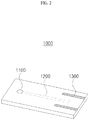
- FIG. 2 is a diagram for describing a biosensor 1000 according to one embodiment of the present application.
- the biosensor 1000 may include a sample introduction part 1100, a reaction part 1200, and/or a contact part 1300. However, all the above components need not be included, and each component may be omitted or duplicated, and a biosensor 1000 may also be manufactured in the form of further including components in addition to the above disclosed components.
- the sample introduction part 1100 may be a region in which a sample is introduced from the outside to the inside of the biosensor 1000.
- the sample introduction part 1100 may be a region forming a channel which allows the sample to be introduced into the reaction part 1200 which will be described below.
- the sample may be a matter including a target substance.
- the sample may be a secretion secreted from a living body.
- the sample may be blood, plasma, serum, saliva, urine, or the like.
- the sample may be a material obtained for a research purpose.
- the sample may be a DNA sample, an RNA sample, or the like obtained from an incident site or a DNA sample, an RNA sample, or the like extracted from an animal cell or a virus.
- the sample provided to the sample introduction part 1100 may move in the interior of the biosensor 1000.
- the sample provided to the sample introduction part 1100 may move from the sample introduction part 1100 to the reaction part 1200.
- the sample may move along a micro channel.
- the sample may move on a membrane.
- the sample provided through the sample introduction part 1100 may move according to a movement method implemented through various manners utilized in the biosensor 1000.
- the reaction part 1200 may be a region in which a specific reaction is performed.
- the reaction part 1200 may be a region in which a specific reaction is performed between a target substance and a capturing substance for capturing the target substance in the biosensor 1000.
- the target substance may be a material to be detected that is included in the sample.
- the target substance may be an antigen.
- the target substance may be an antigen related to a disease detected in blood or the like of a patient with a disease.
- the target substance may be DNA.
- the target substance may be DNA of a virus detected in blood or the like of a patient with a disease.
- the capturing substance may be a material which is specifically bound with the target substance.
- the capturing substance may be an antibody.
- the capturing substance may be an antibody which is specifically bound with the antigen on the basis of an antigen-antibody reaction.
- the capturing substance may be DNA.
- the capturing substance may be DNA which is specifically bound with the DNA on the basis of complementarity of a specific sequence.
- FIG. 3 is a diagram for describing a reaction part 1200 according to one embodiment of the present application.
- the reaction part 1200 may include a magnetic nanoparticle complex 1210, a first electrode 1220, and/or a second electrode 1230. However, all the above components need not be included, and each component may be omitted or duplicated, and a biosensor 1000 may also be manufactured to include the reaction part 1200 in the form of further including components in addition to the above disclosed components.
- the first electrode 1220 may be disposed upstream from the second electrode 1230.
- upstream may mean that the sample is disposed at an upstream based on a movement direction from a position introduced through the sample introduction part 1100 to the reaction part 1200.
- the first electrode 1220 may be closer to the sample introduction part 1100 than the second electrode 1230.
- the first electrode 1220 may be disposed downstream from the second electrode 1230.
- downstream may mean that the sample is disposed at a downstream based on the movement direction from the position introduced through the sample introduction part 1100 to the reaction part 1200.
- the second electrode 1230 may be closer to the sample introduction part 1100 than the first electrode 1220.
- first electrode 1220 and the second electrode 1230 may be disposed to face each other.
- the first electrode 1220 and the second electrode 1230 may have the same distance from the sample introduction part 1100.
- the magnetic nanoparticle complex 1210 may be disposed upstream from the first electrode 1220.
- the magnetic nanoparticle complex 1210 may be disposed upstream from the second electrode 1230.
- the magnetic nanoparticle complex 1210 may be disposed upstream from the first electrode 1220 and the second electrode 1230.
- FIG. 4 is a diagram for describing a magnetic nanoparticle complex 1210 according to one embodiment of the present application.
- the magnetic nanoparticle complex 1210 may include a magnetic nanoparticle 1211, reaction substances 1212, and/or first capturing substances 1213. However, all the above components need not be included, and each component may be omitted or duplicated, and a magnetic nanoparticle complex 1210 may also be provided in the form of further including components in addition to the above disclosed components.
- the magnetic nanoparticle 1211 is a magnetic particle.
- Types of the magnetic nanoparticle 1211 may include iron oxide (Fe 2 O 3 or Fe 3 O 4 ), ferrite (having a form in which one Fe is changed from Fe 3 O 4 into another magnetically related atom, for example, CoFe 2 O 4 or MnFe 2 O 4 )), and/or an alloy (alloys with precious metals to solve an oxidation problem caused due to magnetic atoms and increase conductivity and stability, for example, FePt, CoPt, and the like).
- the magnetic nanoparticle 1211 may be a Fe 2 O 3 particle having a size ranging from 200 nm to 500 nm and having a ferromagnetic property.
- the reaction substance 1212 may be a material for performing at least one of an oxidation reaction and a reduction reaction.
- the reaction substance 1212 is a material having high thermal conductivity and electrical conductivity and may include a transition metal, a post-transition metal, and/or a metalloid.
- the reaction substance 1212 may mean a gold (Au) particle.
- the reaction substance 1212 may mean a silver (Ag) particle.
- the reaction substance 1212 may be fixed to the magnetic nanoparticle 1211.
- the reaction substance 1212 may be fixed to the magnetic nanoparticle 1211 through a chemical bonding force with the magnetic nanoparticle 1211.
- the reaction substance 1212 may fixed to the magnetic nanoparticle 1211 by binding an amine group exposed to the outside of the magnetic nanoparticle 1211.
- the first capturing substance 1213 may be a material which is specifically bound with a first target substance.
- the first target substance may be a target substance (that is, a material to be detected, which is included in a sample).
- the first capturing substance 1213 may be a material which is specifically bound with the target substance.
- the first target substance may be a material which is specifically bound with the target substance.
- the first capturing substance 1213 may specifically bond to a material which is specifically competitively bound with the target substance, competitively with the target substance.
- the first capturing substance 1213 may include at least one among an antigen, an antibody, a modified antibody, an antibody analogue, an aptamer, nucleic acid (e.g., DNA, RNA), lipid, and a viral protein antigen.
- an antigen an antibody, a modified antibody, an antibody analogue, an aptamer, nucleic acid (e.g., DNA, RNA), lipid, and a viral protein antigen.
- the first capturing substance 1213 may be an antibody.
- the first capturing substance 1213 may be single stranded DNA including a sequence which is complementarily bound with a single strand of the DNA (i.e., a target substance).
- the first capturing substance 1213 may be fixed to the reaction substance 1212. After the reaction substance 1212 is fixed to the magnetic nanoparticle 1211, the first capturing substance 1213 may be bound with the reaction substance 1212 to be fixed to the magnetic nanoparticle 1211.
- the magnetic nanoparticle complex 1210 includes the reaction substance 1212.
- the magnetic nanoparticle complex 1210 is fixed in a region adjacent to the second capturing substance 1222 on the first electrode 1220, which will be described below, the magnetic nanoparticle complex 1210 is involved in varying a detection signal in the biosensor 1000 so that it is possible to detect the presence or absence of the target substance using the biosensor 1000.
- the first capturing substance 1213 of the magnetic nanoparticle complex 1210 is fixed through bonding with the reaction substance 1212 and exposed to the outside of the reaction substance 1212 so that reactive degradation between the target substance and the first capturing substance 1213 may be prevented because the reaction substance 1212 is included in the magnetic nanoparticle complex 1210.
- a bonding degree of the reaction substance 1212 is controlled according to an exposure degree of the amine group of the magnetic nanoparticle 1211 so that an optimal magnetic nanoparticle complex 1210, in which a magnetic property of the magnetic nanoparticle complex 1210 may not be extinguished, may be implemented.
- the reaction substance 1212 may be easily replaced with another reaction substance 1212 (e.g., Ag) and the first capturing substance 1213 may be replaced with another first capturing substance 1213 (e.g., an antigen, an antibody, DNA, or the like with respect to another disease) by those skilled in the art.
- another reaction substance 1212 e.g., Ag
- the first capturing substance 1213 may be replaced with another first capturing substance 1213 (e.g., an antigen, an antibody, DNA, or the like with respect to another disease) by those skilled in the art.
- the magnetic nanoparticle complex 1210 In order to synthesize the magnetic nanoparticle complex 1210 according to one embodiment of the present application, 50 ml of a solution containing 1 mg of the magnetic nanoparticle 1211 having a diameter of 500 nm and modified into an amine group per 1ml was subject to ultrasonic treatment for one hour, and then 1 ml of a solution containing 6 mg of HAuCl4 ⁇ 3H2O per 1ml was added while the ultrasonic-treated solution was continuously stirred on ice for one hour.
- the magnetic nanoparticle 1211 which is formed through the above procedure and to which Au was fixed, was washed twice with a phosphate buffered saline (PBS) solution. After the washing, the PBS solution was discarded, and 10 mM dithiobis (succinimidyl propionate) (DSP) dissolved in dimethyl sulfoxide (DMSO) was added to the magnetic nanoparticle, to which Au was fixed, and incubated at room temperature for thirty minutes.
- the DSP may serve as a linker between Au and an anti-PSA detection antibody (i.e., one example of the first capturing substance 1213) which will be added later.
- the magnetic nanoparticle 1211 to which Au was fixed in the incubated solution, was washed with the PBS solution to remove an unbound DSP in the incubated solution. Then, an anti-PSA detection antibody was added to the magnetic nanoparticle 1211, to which Au was fixed, and incubated at room temperature for one hour and incubated at a temperature of 4 °C for sixteen hours.
- the magnetic nanoparticle 1211 to which Au is fixed to which the anti-PSA antibody is fixed through the above procedure was washed twice with the PBS solution and stored at a temperature of 4 °C until further use.
- the magnetic nanoparticle complex 1210 may be synthesized through the above procedure.
- the magnetic nanoparticle complex 1210 is provided in the biosensor 1000 to react with the target substance included in the sample.
- FIG. 5 is a diagram for describing a first electrode 1220 according to one embodiment of the present application.
- the first electrode 1220 is a conductive medium which emits or receives electrons and may include at least one material among materials used as electrodes in the related art, such as carbon, aluminum, platinum, Au, and/or Ag.
- a blocking substance 1221 and a second capturing substance 1222 may be disposed on the first electrode 1220.
- the biosensor 1000 may also be manufactured in the form in which the blocking substance 1221 is not fixed on the first electrode 1220, the second capturing substance 1222 is not disposed thereon, or another material is further formed thereon.
- the blocking substance 1221 may be a material which prevents the target substance included in the sample from being adhered into the first electrode 1220.
- the blocking substance 1221 may be a material which prevents the target substance included in the sample from being fixed to the first electrode 1220.
- the blocking substance 1221 may be a material which prevents other materials other than the target substance included in the sample (i.e., non-target substances) from being adhered into the first electrode 1220.
- the blocking substance 1221 may be a material which prevents the non-target substance from being fixed to the first electrode 1220.
- the blocking substance 1221 may be a protein such as BSA (bovine serum albumin), a saccharide such as sucrose, or a detergent such as Tween-20 or Triton X-100.
- the blocking substance 1221 may be disposed on the first electrode 1220.
- the blocking substance 1221 may be disposed in at least a portion of a region of the first electrode 1220.
- the blocking substance 1221 may be fixed in at least a portion of the region of the first electrode 1220.
- the biosensor 1000 including the magnetic nanoparticle complex 1210 it may be essential for the biosensor 1000 to be manufactured in the form in which the blocking substance 1221 is disposed on the first electrode 1220.
- the biosensor 1000 it may be essential for the biosensor 1000 to be manufactured in the form in which the blocking substance 1221 is disposed on the first electrode 1220.
- a description thereof will be made in detail below together with a result graph according to an experiment.
- the second capturing substance 1222 may be a material which is specifically bound with a second target substance.
- the second target substance may be a target substance (that is, a material to be detected, which is included in the sample).
- the second capturing substance 1222 may be a material which is specifically bonded to the target substance.
- the second capturing substance 1222 may include at least one among an antigen, an antibody, a modified antibody, an antibody analogue, an aptamer, nucleic acid (e.g., DNA, RNA), lipid, and a viral protein antigen.
- an antigen an antibody, a modified antibody, an antibody analogue, an aptamer, nucleic acid (e.g., DNA, RNA), lipid, and a viral protein antigen.
- the second capturing substance 1222 may be an antibody.
- the second capturing substance 1222 may be single stranded DNA including a sequence complementarily binding to a single strand of the DNA (i.e., the target substance).
- the second capturing substance 1222 may be the same material as the first capturing substance 1213.
- the first capturing substance 1213 may be the same anti-PSA antibody.
- the second capturing substance 1222 may be a material different from the first capturing substance 1213.
- the first capturing substance 1213 may react with the PSA but may be an antibody which is specifically bound with an epitope different from an epitope with which the second capturing substance 1222 bind.
- the second capturing substance 1222 may be fixed on the first electrode 1220.
- the blocking substance 1221 is fixed thereon so that the second capturing substance 1222 may not degrade improvement of the detection signal of the blocking substance 1221 in the biosensor 1000.
- BSA is merely an example of the blocking substance 1221 and the anti-PSA detection antibody is merely an example of the second capturing substance 1222. It is obvious that the blocking substance 1221 may be easily replaced with another blocking substance 1221 and the second capturing substance 1222 may be replaced with another second capturing substance 1222 (e.g., an antigen, an antibody, DNA, or the like with respect to another disease) by those skilled in the art.
- another second capturing substance 1222 e.g., an antigen, an antibody, DNA, or the like with respect to another disease
- the anti-PSA antibody may be fixed to a screen-printed carbon electrode (SPCE) through carbodiimide crosslinking.
- SPCE screen-printed carbon electrode
- a surface of the carbon electrode was treated with hexamethylenediamine (HMD) at room temperature for overnight to introduce an amine functional group.
- the carbon electrode was washed with deionized water (i.e., purified water) and then was placed in a mixed solution in which 0.4 M (1-ethyl-3-(3-dimethylaminopropyl)carbodiimide hydrochloride) (EDC), 0.1 M sulfo-(N-hydroxysulfosuccinimide) (NHS), and 0.1 mg/ml anti-PSA antibody is mixed with MES buffer (pH 4.7) and incubated in a controlled humidity chamber at room temperature for two hours.
- EDC (1-ethyl-3-(3-dimethylaminopropyl)carbodiimide hydrochloride)
- NHS 0.1 M sulfo-(N-hydroxysulfosuccinimide)
- anti-PSA antibody is mixed with MES buffer (pH
- the electrode subjected to the above procedure was treated with a 1% BSA solution and slowly stirring thereof, and then the electrode was washed with a PBA solution.
- the washed electrode to which the blocking substance 1221 (e.g., the BSA) and the second capturing substance 1222 (e.g., the anti-PSA antibody) are fixed, is blow-dried with N 2 gas and then stored at a temperature of 4 °C until further use.
- the blocking substance 1221 e.g., the BSA
- the second capturing substance 1222 e.g., the anti-PSA antibody
- the first electrode 1220 to which the blocking substance 1221 and the second capturing substance 1222 are fixed may be manufactured.
- the first electrode 1220 may be provided in the biosensor 1000 to react with a target substance included in a sample.
- the first electrode 1220 to which the blocking substance 1221 and the second capturing substance 1222 are fixed may serve as a working electrode in the biosensor 1000.
- a detailed function of the first electrode 1220 will be easily understood through a detailed embodiment described in the operation of the biosensor 1000.
- the second electrode 1230 is a conductive medium which emits or receives electrons and may include at least one material among materials used as electrodes in the related art, such as carbon, aluminum, platinum, Au, and/or Ag.
- the second electrode 1230 may be separately disposed from the first electrode 1220.
- the second electrode 1230 may be physically separated from the first electrode 1220.
- the second electrode 1230 may be an electrode different from the first electrode 1220.
- the second electrode 1230 being different from the first electrode 1220 may include a case in which material compositions constituting the first electrode 1220 and the second electrode 1230 are different from each other as well as a case in which, even when the material compositions constituting the first electrode 1220 and the second electrode 1230 are the same, there are two electrodes in which the first electrode 1220 and the second electrode 1230 are physically separated and divided.
- the second electrode 1230 may serve as a reference electrode in the biosensor 1000.
- a detailed function of the second electrode 1230 will be easily understood through a detailed embodiment described in the operation of the biosensor 1000.
- the contact part 1300 may be made of a material having electrical conductivity.
- the contact part 1300 is a conductive medium which emits or receives electrons and may include at least one material among materials used as electrodes in the related art, such as carbon, aluminum, platinum, Au, and/or Ag.
- the contact part 1300 may include a first terminal electrically connected to the first electrode 1220 and a second terminal electrically connected to the second electrode 1230.
- the contact part 1300 may include a fourth electrode electrically connected to the first electrode and a fifth electrode electrically connected to the second electrode 1230.
- At least a portion of the contact part 1300 may be exposed to the outside of the biosensor 1000.
- the contact part 1300 includes the first terminal electrically connected to the first electrode 1220 and the second terminal electrically connected to the second electrode 1230
- at least a portion of the first terminal and at least a portion of the second terminal may be exposed to the outside of the biosensor 1000.
- the contact part 1300 is made of an electrode material
- at least a portion of the fourth electrode electrically connected to the first electrode 1220 and at least a portion of the fifth electrode electrically connected to the second electrode 1230 may be exposed to the outside of the biosensor 1000.
- the contact part 1300 may be implemented in the form in which the first electrode 1220 and the fourth electrode are formed as a single electrode and the second electrode 1230 and the fifth electrode are formed as a single electrode.
- the first electrode 1220 and the fourth electrode being formed as a single electrode may mean a form in which one side of the single electrode is connected to the reaction part 1200 and is fixed to the second capturing substance 1222, and the other side of the single electrode is exposed to the outside of the biosensor 1000.
- the second electrode 1230 and the fifth electrode being formed as a single electrode may mean a form in which one side of the single electrode is connected to the reaction part 1200 and the other side of the single electrode is exposed to the outside of the biosensor 1000.
- the contact part 1300 may have a function of performing electrical connection to the detection device 2000 which will be described below.
- a region of the contact part 1300 exposed to the outside of the biosensor 1000 may have the function of performing electrical connection to the detection device 2000.
- An electrical connection between the contact part 1300 and the detection device 2000 may be implemented through a physical connection.
- the contact part 1300 may implement the electrical connection with the detection device 2000 in the form of being inserted into the detection device 2000.
- the contact part 1300 is electrically connected to the detection device 2000 so that a voltage applied between the first electrode 1220 and the second electrode 1230 may be controlled through a controller 2400 of the detection device 2000.
- the contact part 1300 according to one embodiment of the present application is electrically connected to the detection device 2000 to allow the detection device 2000 to detect information on voltages and/or currents of the first electrode 1220 and the second electrode 1230 in the biosensor 1000.
- a detailed function of the contact part 1300 according to one embodiment of the present application will be easily understood through a detailed embodiment described in the operation of the biosensor 1000.
- a conventionally used target detection manner of the biosensor 1000 may be broadly classified into a sandwich manner and a competitive manner.
- the biosensor 1000 including the magnetic nanoparticle complex 1210 an operation of detecting a target substance in a sample using a sandwich manner will be described, and only a configuration and only an operation, which should be changed in an operation of detecting a target substance in a sample using a competitive manner, will be described in detail.
- FIG. 6 is a diagram for describing a general operation of the biosensor 1000 according to one embodiment of the present application.
- a sample may be provided to the sample introduction part 1100 of the biosensor 1000.
- a target substance may be included in the sample.
- the target substance and a non-target substance may be included in the sample.
- the non-target substance may mean a material which is present in the sample but is not specifically bound with the first capturing substance 1213 and the second capturing substance 1222.
- the sample When the sample is provided to the sample introduction part 1100 of the biosensor 1000, the sample may move along a channel in the biosensor 1000.
- a micro channel (or a micro fluidic channel) is formed in the biosensor 1000, and the sample provided to the sample introduction part 1100 may move due to an action of a capillary force.
- the sample may pass through the sample introduction part 1100 to move to the reaction part 1200.
- the magnetic nanoparticle complex 1210 may be present in the reaction part 1200.
- the magnetic nanoparticle complex 1210 may include the magnetic nanoparticle 1211, the reaction substances 1212, and the first capturing substances 1213.
- the first capturing substance 1213 may be an antibody capable of specifically binding with a target substance (i.e., a first target substance).
- the antibody may include all of fragment type antibodies such as fragment antigen binding (Fab) including a CDR region, fragment crystallizable (Fc), and the like and/or full antibodies such as immunoglobulin G(IgG) and the like.
- the target substance included in the sample moving from the sample introduction part 1100 may be specifically bound with the magnetic nanoparticle complex 1210.
- the target substance may be bound with the first capturing substance 1213 of the magnetic nanoparticle complex 1210.
- the magnetic nanoparticle complex 1210 and the target substance may perform a binding according to an antigen-antibody reaction.
- the antigen-antibody reaction may be performed in the reaction part 1200 of the biosensor 1000.
- the first electrode 1220, to which the second capturing substance 1222 is fixed, and the second electrode 1230 may be fixed to the reaction part 1200.
- the magnetic nanoparticle complex 1210 bound with the target substance may be captured by the second capturing substance 1222 fixed on the first electrode 1220.
- the second capturing substance 1222 fixed on the first electrode 1220 may be bound with the target substance (i.e., a second target substance) bound with the magnetic nanoparticle complex 1210 and, the binding between a second capturing substance and the target substance, so, the magnetic nanoparticle complex 1210 may be captured by the second capturing substance 1222.
- the antibody 1222 fixed on the first electrode 1220 may react with an antigen (i.e., a target substance) in the sample.
- the antigen bound with the antibody 1222 fixed on the first electrode 1220 may be bound with the magnetic nanoparticle complex 1210.
- antigen is bound to the antibody 1222 to which the first electrode 1220 is fixed, after bound with the antibody 1222, may be bound with the antibody 1212 of the magnetic nanoparticle complex 1210.
- the first target substance and the second target substance may be the same material.
- the sample excluding the magnetic nanoparticle complex 1210 and the target substance, which are captured by the second capturing substance 1222 of the first electrode 1220 may move downstream based on the reaction part 1200.
- the target substance, the non-target substance, and magnetic nanoparticle complex 1210, which are not captured by the first electrode 1220 may move to a sample disposal unit(not shown).
- a plurality of samples, which are not captured by the first electrode 1220, may be collected in the sample disposal unit.
- a current value depending on a voltage applied to the first electrode 1220 and the second electrode 1230 i.e., a current value output according to the applied voltage
- the current value being changed according to the voltage applied to the first electrode 1220 and the second electrode 1230 may be caused by a variation in characteristic of the material on the first electrode 1220 or the second electrode 1230 according to oxidation/reduction of the reaction substance 1212 fixed to the magnetic nanoparticle complex 1210.
- the biosensor 1000 using the magnetic nanoparticle complex 1210 may be provided as a diagnostic kit of a competitive manner.
- the first capturing substance 1213 of the magnetic nanoparticle complex 1210 may be an antigen.
- the first capturing substance 1213 may be bound with the second capturing substance 1222 on the first electrode 1220 in competition with the antigen (i.e., the target substance) in the sample.
- the first target substance captured by the first capturing substance 1213 may be the second capturing substance 1222.
- the antigen(i.e., the target substance) in the sample may also be bound with the second capturing substance 1222 on the first electrode 1220.
- the second target substance of the second capturing substance 1222 may be the first capturing substance 1213 and the antigens in the sample.
- the first capturing substance 1213 and the antigens in the sample are competitively bound with the second capturing substance 1222 so that, as an amount of antigens in the sample increases, an amount of the first capturing substance 1213 captured by the second capturing substance 1222 on the first electrode 1220 may decrease.
- an amount of the target substance (i.e., the antigen) captured by the second capturing substance 1222 fixed on the first electrode 1220 may decrease. Consequently, as compared with a case in which the target substance is not included in the sample, when a plurality of the target substances are included in the sample, the current value depending on the voltage applied to the first electrode 1220 and the second electrode 1230 may be detected as a small. Unlike the biosensor 1000 of the sandwich manner, when the measured detection value is small, it can be confirmed that the amount of the target substance in the sample is large.
- the first capturing substance 1213 of the magnetic nanoparticle complex 1210 may be an antibody.
- the first capturing substance 1213 may be bound with the antigen (i.e., the target substance) in the sample.
- the first capturing substance 1213 may be bound with the second capturing substance 1222 on the first electrode 1220.
- the second capturing substance 1222 may be an antigen.
- the second target substance of the second capturing substance 1222 may be an antibody. In other words, the second target substance of the second capturing substance 1222 may be the first capturing substance 1213.
- the antigen (i.e., the target substance) in the sample and the second capturing substance 1222 fixed to the electrode may compete for the first capturing substance 1213.
- an amount of the first capturing substance 1213 bound with the second capturing substance 1222 may decrease.
- the first capturing substance 1213 bound with the second capturing substance 1222 may increase.
- the current value depending on the voltage applied to the first electrode 1220 and the second electrode 1230 may be detected as a small value.
- the measured detection value is small, it can be confirmed that the amount of the target substance in the sample is large.
- the magnetic nanoparticle complex 1210 having a magnetic property may be provided in the reaction part 1200 of the biosensor 1000. Consequently, a state condition of the reaction part 1200 may be changed to control mobility of the magnetic nanoparticle complex 1210.
- the other materials may include the target substance, the non-target substance, and the magnetic nanoparticle complex 1210 which are not captured by the first electrode 1220.
- the magnetic nanoparticle complex 1210 which are not captured by the first electrode 1220 and the like are disposed in a region adjacent to the first electrode 1220, in order to solve a problem in that, even though the target substance is not included in the sample, a negative signal is detected and thus a false positive is diagnosed, other materials are washed by varying the state condition of the reaction part 1200 such that there is an advantage of deriving improvement in accuracy and sensitivity of the biosensor 1000 and reduction in background as effects.
- a method of changing the state condition of the reaction part 1200 may include 1) changing a magnetic field formed in the reaction part 1200, 2) changing an electric field formed in the reaction part 1200, and 3) changing the magnetic field and the electric field formed in the reaction part 1200.
- the magnetic field formed in the reaction part 1200 may be changed by placing a magnet in a region adjacent to the first electrode 1220 and then placing the magnet in a region opposite to the first electrode.
- a detailed operation of the biosensor 1000 related to the above description will be described below with reference to FIG. 7 .
- the electric field may be changed by changing a magnitude and a frequency of a voltage applied between the first electrode 1220 and the second electrode 1230.
- the magnetic field and/or the electric field which is formed in the reaction part 1200 may be changed by changing a current applied to the third electrode.
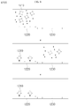
- FIG. 7 is a diagram for describing an operation of a biosensor 1000 according to a first embodiment of the present application.
- a mechanism for forming a magnetic field may be disposed at a lower end and an upper end of the first electrode 1220 of the reaction part 1200, and turning ON/OFF of the mechanism for forming a magnetic field may be controlled.
- the formation of the magnetic field may also be controlled by a gap between the magnet and the first electrode 1220.
- the gap between the magnet and the first electrode 1220 is small, the magnetic field in the reaction part 1200 becomes stronger.
- the magnet is alternately positioned above or below the first electrode 1220, or when the turning ON/OFF of the mechanism for forming a magnetic field, which is positioned above or below, is alternately performed, movement of the magnetic nanoparticle complex 1210 is changed according to the number of times or a retention time.
- the sample When the sample is provided to the sample introduction part 1100 of the biosensor 1000, the sample may move along a channel in the biosensor 1000.
- an additional electrode different from the first electrode 1220 and the second electrode 1230 may be provided in the sample introduction part 1100 of the biosensor 1000.
- the sample may pass through the sample introduction part 1100 to move to the reaction part 1200.
- the magnetic nanoparticle complex 1210 may be present in the reaction part 1200.
- the mechanisms for generating a magnetic field positioned above or below the first electrode 1220 of the reaction part 1200 is turned off, the magnetic nanoparticle complex 1210 and the sample may move from the sample introduction part 1100 in a downstream direction.
- the target substance may be bound with the first capturing substance 1213 of the magnetic nanoparticle complex 1210.
- the magnetic nanoparticle complex 1210 and the target substance may perform a binding according to an antigen-antibody reaction.
- the antigen-antibody reaction may be performed in the reaction part 1200 of the biosensor 1000.
- the target substance may be bound with the second capturing substance 1222 of the first electrode 1220.
- the magnetic nanoparticle complex 1210 bound with the target substance which is bound with the second capturing substance 1222 may be captured by the second capturing substance 1222 to be involved in a variation in detection signal of the biosensor 1000.
- the mechanism for generating a magnetic field positioned above the first electrode 1220 of the reaction part 1200 when the mechanism for generating a magnetic field positioned above the first electrode 1220 of the reaction part 1200 is turned off and the mechanism for generating a magnetic field positioned below the first electrode 1220 of the reaction part 1200 is turned on, movement of the magnetic nanoparticle complex 1210 may be guided toward the first electrode 1220 of the reaction part 1200.
- a reaction between the target substance and the first capturing substance 1213 of the magnetic nanoparticle complex 1210 and/or between the target substance and the second capturing substance 1222 of the first electrode 1220 may be improved.
- the movement of the magnetic nanoparticle complex 1210 may be guided toward the upper side of the first electrode 1220 of the reaction part 1200.
- a magnetic nanoparticle complex 1210 which is not captured by the second capturing substance 1222 of the first electrode 1220 is guided toward the upper side of the first electrode 1220 so that the magnetic nanoparticle complex 1210 which is not captured by a region adjacent to the second capturing substance 1222 of the first electrode 1220 may be washed.
- the magnetic nanoparticle complex 1210 which is not captured by the second capturing substance 1222 of the first electrode 1220 is guided toward the upper side of the first electrode 1220 so that the magnetic nanoparticle complex 1210 which is not captured by the region adjacent to the second capturing substance 1222 of the first electrode 1220 may be removed.
- a first environmental condition in which the mechanism for generating a magnetic field positioned above the first electrode 1220 of the reaction part 1200 is turned off and the mechanism for generating a magnetic field positioned below the first electrode 1220 of the reaction part 1200 is turned on
- a second environmental condition in which the mechanism for generating the magnetic field positioned below the first electrode 1220 of the reaction part 1200 is turned off and the mechanism for generating a magnetic field positioned above the first electrode 1220 of the reaction part 1200 is turned off
- the first environmental condition is set in the reaction part 1200
- a certain period of time elapses, and then the second environmental condition is set in the reaction part 1200
- it may be controlled such that the second environmental condition is set after the first environmental condition is set in the reaction part 1200, and then the first environmental condition and the second environmental condition are sequentially and repeatedly set.
- a specific binding of the target substance included in the sample with the magnetic nanoparticle complex 1210 may be performed more actively.
- an amount of the specific binding of the target substance included in the sample with the magnetic nanoparticle complex 1210 may increase. Consequently, sensitivity of the biosensor 1000 may be improved.
- the magnetic nanoparticle 1211, the non-target substance, and the target substance, which are not captured by the second capturing substance 1222, may move downstream from the reaction part 1200.
- the presence or absence of the target substance in the sample may be confirmed by detecting a current value depending on a voltage applied to the first electrode 1220 and the second electrode 1230.
- a third electrode in the form of a coil may be disposed above and below the reaction part 1200.
- a current applied to the third electrodes disposed above and below the reaction part 1200 is adjusted such that a magnetic field formed in the reaction part 1200 may be controlled.
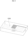
- FIG. 8 is an enlarged view for describing an arrangement of a third electrode for providing a magnetic field according to one embodiment of the present application.
- FIG. 8 is an enlarged view of the reaction part 1200 in the biosensor 1000 shown in FIG. 2 .
- the third electrodes in the form of a coil may be formed above and below the reaction part 1200.
- a current applied to the third electrodes may be controlled.
- the magnetic nanoparticle complex 1210 may move to a position adjacent to the third electrode located above the reaction part 1200.
- an effect similar to that in which a magnet is disposed below the reaction part 1200 may be obtained.
- the magnetic nanoparticle complex 1210 may move to a position adjacent to the third electrode located below the reaction part 1200.
- the current applied to the third electrode disposed above the reaction part 1200 and the third electrode disposed below the reaction part 1200 is controlled such that movement of the magnetic nanoparticle complex 1210 may be controlled.
- the movement of the magnetic nanoparticle complex 1210 may be controlled in the form of repeatedly performing an operation of applying a first current to the third electrode disposed above the reaction part 1200 and applying a second current to the third electrode disposed below the reaction part 1200.
- a biosensor 1000 according to one embodiment of the present application may include a first electrode 1220 to which a blocking substance 1221 is fixed. More specifically, the biosensor 1000 according to one embodiment of the present application may include the first electrode 1220 to which BSA is fixed.
- the BSA being fixed on the first electrode 1220, performing a blocking function of simply preventing a target substance contained in a sample from being adhered on the first electrode 1220, in addition to may perform a function of assisting an oxidation/reduction action of the reaction substance 1212 of the magnetic nanoparticle complex 1210.
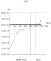
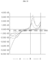
- FIG. 9 is a graph for describing a variation in current over a voltage of the biosensor 1000 including the first electrode 1220 to which the BSA is fixed according to one embodiment of the present application.
- a sample including a target substance was provided to the biosensor 1000 including the first electrode 1220 to which the BSA was not fixed, a second capturing substance 1222 was fixed, and then detection is performed, and as a result, it was confirmed that a variation in current according to a variation in voltage was not detected (see BSAX in the illustrated graph).
- the target substance is present in the sample may be detected using the biosensor 1000 including the first electrode 1220 to which the BSA and the second capturing substance 1222 are fixed, and the blocking substance 1221 (e.g., the BSA) may perform a function of assisting oxidation/reduction action in the biosensor 1000 including the magnetic nanoparticle complex 1210.
- the blocking substance 1221 e.g., the BSA
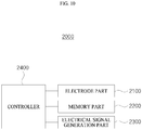
- FIG. 10 is a diagram for describing a detection device 2000 according to one embodiment of the present application.
- the detection device 2000 may include an electrode part 2100, a memory part 2200, an electrical signal generation part 2300, and/or a controller 2400. However, all the above components need not be included, and each component may be omitted or duplicated, and a detection device 2000 may also be manufactured in the form of further including components in addition to the above disclosed components.
- the electrode part 2100 is a conductive medium which emits or receives electrons and may include at least one material among materials used as electrodes in the related art, such as carbon, aluminum, platinum, Au, and/or Ag.
- the electrode part 2100 may have a function of performing electrical connection to the contact part 1300 of the biosensor 1000.
- the electrode part 2100 may include a first electrode terminal, which is electrically connected to the first electrode 1220 of the biosensor 1000, and a second electrode terminal which is electrically connected to the second electrode 1230 of the biosensor 1000.
- the contact part 1300 of the biosensor 1000 includes a fourth electrode electrically connected to the first electrode and a fifth electrode electrically connected to the second electrode 1230
- the first electrode terminal may be electrically connected to the first electrode 1220 and the fourth electrode
- the second electrode terminal may be electrically connected to the second electrode 1230 and the fifth electrode.
- the electrode part 2100 is electrically connected to the biosensor 1000 to allow the detection device 2000 to detect information on voltages and/or currents of the first electrode 1220 and the second electrode 1230 in the biosensor 1000.
- the electrode part 2100 may be electrically connected to the biosensor 1000 to perform a function of transferring electrical energy (e.g., a voltage and/or a current) generated in the detection device 2000 to the first electrode 1220 and the second electrode 1230 of the biosensor 1000.
- electrical energy e.g., a voltage and/or a current
- the electrode part 2100 may be physically connected to the contact part 1300 of the biosensor 1000.
- the biosensor 1000 is insertion-coupled to a portion of the detection device 2000 so that the contact part 1300 of the biosensor 1000 may be in contact with the electrode part 2100 of the detection device 2000.
- a function of the electrode part 2100 according to one embodiment of the present application will be easily understood through a detailed embodiment described in an operation of the detection device 2000.
- the memory part 2200 may perform a function of temporarily or non-temporarily storing information.
- the memory part 2200 may be implemented in the form of including a hard disk drive (HDD), a solid state drive (SSD), a flash memory, a read-only memory (ROM), and/or a random access memory (RAM).
- the memory part 2200 may be implemented in the form of being connected to another server through wireless communication to store necessary information in another server.
- the present disclosure is not limited thereto, and a functional unit which performs a function of storing information to allow the detection device 2000 to utilize the information may correspond to the memory part 2200 regardless of whether the functional unit has a hardware or software structure.
- the memory part 2200 may store information on voltage values which are to be applied to the first electrode 1220 and the second electrode 1230 of the biosensor 1000.
- the memory part 2200 may store information on voltage values of the first electrode 1220 and the second electrodes 1230, wherein the voltage values should be applied thereto.
- a function of the memory part 2200 according to one embodiment of the present application will be easily understood through a detailed embodiment described in the operation of the detection device 2000.
- the electrical signal generation part 2300 may perform a function of generating a voltage and/or a current.
- the electrical signal generation part 2300 may include direct current (DC) voltage/current generators.
- the electrical signal generation part 2300 may include a pulse width modulation (PWM) output generator.
- the electrical signal generation part 2300 may include an alternating current (AC) standard voltage generator.
- the electrical signal generation part 2300 may be implemented in the form of an electronic circuit such as an integrated circuit which performs a function of generating a voltage and/or a current and, alternatively, in the form of a computer or a device similar to the computer according to hardware, software, or a combination thereof. According to one embodiment of the present application, the electrical signal generation part 2300 may be implemented in the form of being included in the controller 2400.
- a function of the electrical signal generation part 2300 according to one embodiment of the present application will be easily understood through a detailed embodiment described in the operation of the detection device 2000.
- the controller 2400 may control an overall operation of the detection device 2000. To this end, the controller 2400 may perform calculation and processing on various pieces of information and control operations of components of the detection device 2000.
- the controller 2400 may be implemented as a computer or a device similar to the computer according to hardware, software, or a combination thereof.
- the controller 2400 may be provided in the form of an electronic circuit such as a central processing unit (CPU) chip which processes an electrical signal and performs a control function.
- the controller 2400 may be provided in the form of a program which drives the controller 2400 in terms of hardware.
- the controller 2400 may control the electrical signal generation part 2300 to provide a voltage and/or a current to the biosensor 1000 through the electrode part 2100.
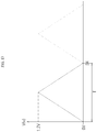
- the controller 2400 may control a voltage including a first stage of increasing a voltage applied between the first electrode 1220 and the second electrode 1230 and a second stage of decreasing the voltage to be provided. This may be to provide a circulating voltage to perform qualitative analysis and/or quantitative analysis of the target substance included in the sample.
- the controller 2400 may control a voltage, which is applied as a voltage that is higher than at least one of the lowest voltage in the first stage and the lowest voltage in the second stage for a predetermined time or more, to be provided.
- the stabilization means that, in a current graph according to a voltage in an operation of providing the circulating voltage, a potential/reduction potential is relatively increased when a current is maximum and/or a potential/oxidation potential value is relatively decreased when the current is minimum.
- the stabilization means that, in the current graph according to the voltage in the operation of providing the circulating voltage, a maximum current value is relatively increased and/or a minimum current value is relatively decreased.
- the stabilization means that, in the current graph according to the voltage in the operation of providing the circulating voltage, a current depending on oxidation (a current according to an increase of a voltage) corresponding to a voltage of 0 V and a current depending on reduction (a current according to a decrease of the voltage) coincide with each other relatively more.
- the controller 2400 may control the environmental condition of the reaction part 1200 of the biosensor 1000 to be changed through the electrode part 2100 or a separate magnetic field forming mechanism.
- the controller 2400 controls an electrical signal provided to the first electrode 1220, the second electrode 1230, and/or the third electrode, which is electrically connected to the electrode part 2100, to change the environmental condition of the reaction part 1200 of the biosensor 1000.
- the controller 2400 may control turning ON/OFF of the separate magnetic forming mechanism included in the detection device 2000 to change the environmental condition of the reaction part 1200 of the biosensor 1000.
- an operation of the detection device 2000 is performed under the control of the controller 2400.
- a function of the controller 2400 according to one embodiment of the present application will be easily understood through a detailed embodiment described in the operation of the detection device 2000.
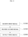
- FIG. 11 is a diagram for describing an operation of the detection device 2000 according to one embodiment of the present application.
- the detection device 2000 may provide a second signal (S2000) and may detect a third signal (S3000).
- S2000 second signal
- S3000 third signal
- each operation is not necessarily performed, and each operation may be omitted or repeated, and other procedures may be additionally performed.
- the detection device 2000 may receive the first signal (SI000).
- the first signal may mean a signal received when a sample is introduced to the sample introduction part 1100 of the biosensor 1000 through a separate electrode or the like which is additionally provided in the biosensor 1000.
- the first signal may mean a signal received when the sample reaches the reaction part 1200 of the biosensor 1000 through the separate electrode or the like which is additionally provided in the biosensor 1000.
- the first signal may mean a signal received when the sample reaches the reaction part 1200 of the biosensor 1000 through the first electrode 1220 and/or the second electrode 1230 of the biosensor 1000.
- the first signal may mean a signal received when the sample reaches the sample disposal unit of the biosensor 1000 through the first electrode 1220 and/or the second electrode 1230 of the biosensor 1000.
- the controller 2400 of the detection device 2000 may begin to provide the second signal (S2000).
- the detection device 2000 may provide the second signal (S2000).
- the second signal may be a signal by which the detection device 2000 controls one operation of the biosensor 1000.
- An example of the second signal may mean 1) a signal transmitted to the biosensor 1000 so as to change the environmental condition of the reaction part 1200 of the biosensor 1000, 2) in order to determine whether the target substance is captured in the sample introduced into the biosensor 1000 by detecting a current depending on a variation in voltage applied to the first electrode 1220 and the second electrode 1230 of the biosensor 1000, a signal transmitted to the biosensor 1000 so as to provide a voltage including a first stage of increasing a voltage applied between the first electrode 1220 and the second electrode 1230 and a second stage of decreasing the voltage applied therebetween, and/or 3) in order to stabilize the curve of the current, a signal transmitted to the biosensor 1000 so as to provide a voltage which is higher than at least one of the lowest voltage in the first stage and the lowest voltage in the second stage and is applied for a predetermined time or more.
- FIG. 12 is a diagram for describing the provision of the second signal (S2000) according to one embodiment of the present application.
- the detection device 2000 may provide a second-first signal (S2100), provide a second-second signal (S2200), and provide a second-third signal (S2300).
- S2100 second-first signal
- S2200 second-second signal
- S2300 second-third signal
- each operation is not necessarily performed, and each operation may be omitted or repeated, and other procedures may be additionally performed.
- the provision of the second-first signal (S2100) may mean an operation in which an electrical signal is transmitted from the detection device 2000 to the biosensor 1000 in order to change the environmental condition of the reaction part 1200 of the biosensor 1000.
- the controller 2400 provides an electrical signal for changing magnitudes, frequencies, and the like of the voltages applied to the first electrode 1220 and the second electrode 1230 to change the environmental condition of the reaction part 1200 of the biosensor 1000 so that movement of the magnetic nanoparticle complex 1210, the target substance, and/or the non-target substance, which are located in the reaction part 1200 of the biosensor 1000, may be changed.
- the controller 2400 provides an electrical signal for changing a current applied to the coil-shaped third electrode included in the biosensor 1000 to change the environmental condition of the reaction part 1200 of the biosensor 1000 so that movement of the magnetic nanoparticle complex 1210, the target substance, and/or the non-target substance, which are located in the reaction part 1200 of the biosensor 1000, may be changed.
- the provision of the second-second signal (S2200) may mean an operation in which, prior to the provision of the second-third signal (S2300), an electrical signal for applying a specific voltage is transmitted from the detection device to the biosensor 1000 so as to stabilize the curve of the current according to the provision of the second-third signal (S2300).
- the provision of the second-second signal may perform a function of inducing oxidation/reduction reactions of the magnetic nanoparticle complex 1210 captured by second capturing substance of the first electrode 1220 and stabilizing the curve of the current according to the second-third signal.
- the second-second signal S2200
- specific voltages are applied to the first electrode 1220 and the second electrode 1230 of the biosensor 1000 for a predetermined time or more so that and the reaction substance 1212 of the magnetic nanoparticle complex 1210 undergoes oxidation pretreatment.
- a voltage of at least 1 V or more may be applied between the first electrode 1220 and the second electrode 1230 of the biosensor 1000 for at least two seconds.
- a voltage of 1.5 V may be applied between the first electrode 1220 and the second electrode 1230 of the biosensor 1000 for ten seconds.
- the second-second signal S2200
- specific voltages are applied to the first electrode 1220 and the second electrode 1230 of the biosensor 1000 for a predetermined time or more so that the reaction substance 1212 of the magnetic nanoparticle complex 1210 may undergo oxidation pretreatment, and then the voltage to which applied to the first electrode 1220 and the second electrode 1230 of the biosensor 1000 is decreased so that the reaction substance 1212 of the magnetic nanoparticle complex 1210 may undergo reduction pretreatment.
- a voltage of at least 1 V or more is applied between the first electrode 1220 and the second electrode 1230 of the biosensor 1000 for at least two seconds, and then a voltage which decreases the voltage between the first electrode 1220 and the second electrode 1230 from at least 1 V or more to at least 0 V or less may be applied.
- a voltage of 1.5 V is applied between the first electrode 1220 and the second electrode 1230 of the biosensor 1000 for ten seconds, and then the voltage applied to the first electrode 1220 and the second electrode 1230 may be decreased from 1.5 V to -0.2 V at a rate of -0.1 V/s.
- the specific voltages are applied to the first electrode 1220 and the second electrode 1230 of the biosensor 1000 for a predetermined time or more so that the reaction substance 1212 of the magnetic nanoparticle complex 1210 may undergo oxidation pretreatment, and then the voltages to which applied to the first electrode 1220 and the second electrode 1230 of the biosensor 1000 are decreased so that the reaction substance 1212 of the magnetic nanoparticle complex 1210 may undergo reduction pretreatment. Thereafter, the voltages to which applied to the first electrode 1220 and the second electrode 1230 of the biosensor 1000 are increased so that the reaction substance 1212 of the magnetic nanoparticle complex 1210 may undergo oxidation pretreatment.
- the voltage of at least 1 V or more is applied between the first electrode 1220 and the second electrode 1230 of the biosensor 1000 for at least two seconds, and then the voltage which decreases the voltage between the first electrode 1220 and the second electrode 1230 from at least 1 V or more to at least 0 V or less may be applied. Thereafter, a voltage which increases the voltage between the first electrode 1220 and the second electrode 1230 from at least 0 V to at least 1 V may be applied.
- the voltage of 1.5 V is applied between the first electrode 1220 and the second electrode 1230 of the biosensor 1000 for ten seconds, and then the voltages applied to the first electrode 1220 and the second electrode 1230 may be decreased from 1.5 V to -0.2 V at a rate of -0.1 V/s. Thereafter, the voltages applied to the first electrode 1220 and the second electrode 1230 may be increased from -0.2 V to 1.5 V at a rate of 0.1 V/s.
- the provision of the second-third signal (S2300) may mean an operation in which, in order to determine whether the target substance is captured by the sample introduced into the biosensor 1000 by detecting a current according to a variation in voltage applied to the first electrode 1220 and the second electrode 1230 of the biosensor 1000, a signal for providing a voltage including a first stage of increasing a voltage applied between the first electrode 1220 and the second electrode 1230 and a second stage of decreasing the voltage applied therebetween is transmitted from the detection device to the biosensor 1000.
- FIG. 13 is a diagram for describing the provision of the second-third signal (S2300) according to one embodiment of the present application.
- the provision of the second-third signal (S2300) may perform a function of providing a switching voltage including a rising potential and a falling potential of a voltage during at least one period T.
- the voltages applied to the first electrode 1220 and the second electrode 1230 of the biosensor 1000 are increased and then decreased so that the detection device 2000 may acquire a detection value depending on oxidation of the reaction substance 1212 of the magnetic nanoparticle complex 1210 and acquire a detection value depending on reduction of the reaction substance 1212 of the magnetic nanoparticle complex 1210.
- a voltage which increases the voltage between the first electrode 1220 and the second electrode 1230 of the biosensor 1000 from at least 0 V or less to at least 1 V or more may be applied, and then a voltage which decreases the voltage between the first electrode 1220 and the second electrode 1230 from at least 1 V or more to at least 0 V or less may be applied.
- the voltages applied to the first electrode 1220 and the second electrode 1230 of the biosensor 1000 may be increased from 0.0 V to 1.2 V at a rate of 0.1 V/s and, subsequently, the voltages applied to the first electrode 1220 and the second electrode 1230 may be decreased from 1.2 V to 0.0 V at a rate of -0.1 V/s.
- the voltages applied to the first electrode 1220 and the second electrode 1230 of the biosensor 1000 are decreased and then increased so that the detection device 2000 may acquire a detection value according to reduction of the reaction substance 1212 of the magnetic nanoparticle complex 1210 and acquire a detection value depending on oxidation of the reaction substance 1212 of the magnetic nanoparticle complex 1210.
- a voltage which decreases the voltage between the first electrode 1220 and the second electrode 1230 of the biosensor 1000 from at least 1 V or more to at least 0 V or less may be applied and, subsequently, a voltage which increases the voltage between the first electrode 1220 and the second electrode 1230 from at least 0 V or less to at least 1 V or more may be applied.
- the voltages applied to the first electrode 1220 and the second electrode 1230 of the biosensor 1000 may be decreased from 1.2 V to 0.0 V at a rate of -0.1 V/s and, subsequently, the voltages applied to the first electrode 1220 and the second electrode 1230 may be increased from 0.0 V to 1.2 V at a rate of 0.1 V/s.
- the detection device 2000 may detect the third signal (S3000).
- the detection of the third signal may mean an operation in which the detection device 2000 detects the currents of the first electrode 1220 and the second electrode 1230 of the biosensor 1000 according to the provision of the second-third signal (S2300).
- FIG. 14 is a diagram for describing an operation of performing a reduction pretreatment prior to the provision of the second-third signal (S2300) according to a third embodiment of the present application.
- the detection device 2000 may operate such that the voltages applied to the first electrode 1220 and the second electrode 1230 of the biosensor 1000 according to the provision of the second-third signal (S2300) are increased from 0.0 V to 1.2 V at a rate of 0.1 V/s and, subsequently, when the second-third signal is provided such that the voltages applied to the first electrode 1220 and the second electrode 1230 are decreased from 1.2 V to 0.0 V at a rate of -0.1 V/s, the reaction part 1200 of the biosensor 1000 undergoes reduction pretreatment prior to the provision of the second-third signal (S2300).
- the provision of the second-second signal (S2200) may be performed such that the reaction part 1200 of the biosensor 1000 undergoes reduction pretreatment.
- the detection device 2000 may operate such that a voltage of 1.5 V is applied to the first electrode 1220 and the second electrode 1230 of the biosensor 1000 for ten seconds according to the provision of the second-second signal and, subsequently, the voltage applied to the first electrode 1220 and the second electrode 1230 is decreased from 1.5 V to -0.2 V at a rate of -0.1 V/s.
- FIG. 15 is a diagram for describing a detection graph of a third signal according to the provision of the second-second signal (S2200) and the provision of the second-third signal (S2300) according to one embodiment of the present application.
- Line A of FIG. 15 shows a current graph according to a voltage due to the second-third signal when the voltages applied to the first electrode 1220 and the second electrode 1230 of the biosensor 1000 are increased from 0.0 V to 1.2 V at a rate of 0.1 V/s according to the provision of the second-third signal (S2300), and when the second-third signal is provided such that the voltages applied to the first electrode 1220 and the second electrode 1230 are decreased from 1.2 V to 0.0 V at a rate of -0.
- Line B of FIG. 15 shows a current graph according to the voltage due to the second-third signal when the voltages corresponding to the voltage graph over time shown in FIG. 13 are applied to the first electrode 1220 and the second electrode 1230.
- Line C of FIG. 15 shows a current graph according to the voltage due to the second-third signal when the voltages applied to the first electrode 1220 and the second electrode 1230 of the biosensor 1000 are increased from 0.0 V to 1.2 V at a rate of 0.1 V/s according to the provision of the second-third signal (S2300), and when the second-third signal is provided such that the voltages applied to the first electrode 1220 and the second electrode 1230 are decreased from 1.2 V to 0.0 V at a rate of -0. 1 V/s, prior to the provision of the second-third signal (S2300), voltages of 1.5 V are applied to the first electrode 1220 and the second electrode 1230 of the biosensor 1000 for ten seconds according to the provision of the second-second signal (S2200).
- FIG. 16 is a diagram for describing an operation of performing oxidation pretreatment prior to the provision of the second-third signal (S2300) according to the fourth embodiment of the present application.
- the detection device 2000 may operate such that the voltages applied to the first electrode 1220 and the second electrode 1230 of the biosensor 1000 are decreased from 1.2 V to 0.0 V at a rate of -0.1 V/s according to the provision of the second-third signal (S2300) and, subsequently, when the second-third signal(S2300) is provided such that the voltages applied to the first electrode 1220 and the second electrode 1230 are increased from 0.0 V to 1.2 V at a rate of 0.1 V/s, the reaction part 1200 of the biosensor 1000 undergoes reduction pretreatment prior to the provision of the second-third signal (S2300).
- the provision of the second-second signal (S2200) may be performed such that the reaction part 1200 of the biosensor 1000 undergoes oxidation pretreatment.
- the detection device 2000 may operate such that a voltage of 1.5 V may be applied to the first electrode 1220 and the second electrode 1230 of the biosensor 1000 for ten seconds according to the provision of the second-second signal (S2200).
- the detection device 2000 may operate such that the voltage of 1.5 V is applied to the first electrode 1220 and the second electrode 1230 of the biosensor 1000 for ten seconds according to the provision of the second-second signal (S2200) and, subsequently, the voltage applied to the first electrode 1220 and the second electrode 1230 may be decreased from 1.5 V to -0.2 V at a rate of -0.1 V/s and then increased from -0.2 V to 1.5 V at a rate of 0.1 V/s.
- the detection device 2000 may operate such that the voltage of 1.5 V is applied to the first electrode 1220 and the second electrode 1230 of the biosensor 1000 for ten seconds according to the provision of the second-second signal (S220) and, subsequently, the voltage applied to the first electrode 1220 and the second electrode 1230 is increased from - 0.2 V to 1.5 V at a rate of 0.1 V/s.
- the method of analyzing the presence or absence of the target substance using cyclic voltammetry has been disclosed in detail. However, according to one embodiment of the present application, it is also possible to analyze the presence or absence of the target substance using differential pulse voltammetry.
- a pulse signal may be provided at a time of the provision of the second-third signal (S2300) in the form of a voltage having 1) a step potential of 4 mV in a range of 1 v to 0 V, 2) a modulation amplitude of -50 mV, 3) a modulation time of 5 seconds, and 4) an interval time of 200 ms.
- a graph of a current depending on an applied pulse may be illustrated, and whether the illustrated graph has a maximum current value or a minimum current value is determined so that the presence of the target substance in the sample may be determined.
Landscapes
- Health & Medical Sciences (AREA)
- Life Sciences & Earth Sciences (AREA)
- Immunology (AREA)
- Chemical & Material Sciences (AREA)
- Engineering & Computer Science (AREA)
- Molecular Biology (AREA)
- Urology & Nephrology (AREA)
- Hematology (AREA)
- Biomedical Technology (AREA)
- Physics & Mathematics (AREA)
- General Health & Medical Sciences (AREA)
- Pathology (AREA)
- Analytical Chemistry (AREA)
- General Physics & Mathematics (AREA)
- Biochemistry (AREA)
- Medicinal Chemistry (AREA)
- Biotechnology (AREA)
- Cell Biology (AREA)
- Microbiology (AREA)
- Food Science & Technology (AREA)
- Chemical Kinetics & Catalysis (AREA)
- Spectroscopy & Molecular Physics (AREA)
- Electrochemistry (AREA)
- Nanotechnology (AREA)
- Inorganic Chemistry (AREA)
- Apparatus Associated With Microorganisms And Enzymes (AREA)
- Investigating Or Analyzing Materials By The Use Of Magnetic Means (AREA)
Applications Claiming Priority (1)
| Application Number | Priority Date | Filing Date | Title |
|---|---|---|---|
| PCT/KR2018/009115 WO2020032294A1 (fr) | 2018-08-09 | 2018-08-09 | Biocapteur utilisant des nanoparticules magnétiques, dispositif de détection et procédé de détection utilisant ledit biocapteur |
Publications (2)
| Publication Number | Publication Date |
|---|---|
| EP3835785A1 true EP3835785A1 (fr) | 2021-06-16 |
| EP3835785A4 EP3835785A4 (fr) | 2022-06-22 |
Family
ID=69414184
Family Applications (1)
| Application Number | Title | Priority Date | Filing Date |
|---|---|---|---|
| EP18929343.4A Pending EP3835785A4 (fr) | 2018-08-09 | 2018-08-09 | Biocapteur utilisant des nanoparticules magnétiques, dispositif de détection et procédé de détection utilisant ledit biocapteur |
Country Status (6)
| Country | Link |
|---|---|
| US (3) | US11041854B2 (fr) |
| EP (1) | EP3835785A4 (fr) |
| JP (2) | JP6989183B2 (fr) |
| KR (2) | KR102426791B1 (fr) |
| CN (1) | CN112689759A (fr) |
| WO (1) | WO2020032294A1 (fr) |
Families Citing this family (8)
| Publication number | Priority date | Publication date | Assignee | Title |
|---|---|---|---|---|
| EP3835785A4 (fr) | 2018-08-09 | 2022-06-22 | BBB Inc. | Biocapteur utilisant des nanoparticules magnétiques, dispositif de détection et procédé de détection utilisant ledit biocapteur |
| CN115135766A (zh) * | 2020-02-21 | 2022-09-30 | 爱普群生生物技术公司 | 用于适体筛选的装置、方法和组合物 |
| KR102348003B1 (ko) | 2020-10-08 | 2022-01-07 | 연세대학교 산학협력단 | 이중 항체 연결 면역 샌드위치 분석을 이용한 타겟 바이오마커 검출방법 |
| CN118339454A (zh) * | 2021-10-29 | 2024-07-12 | 花王株式会社 | 新型侧向层析检测 |
| KR102865506B1 (ko) * | 2022-05-30 | 2025-09-29 | 주식회사 바이오소닉스 | 용액의 흐름 조절이 개선된 진단 카트리지 |
| KR102924583B1 (ko) * | 2023-02-28 | 2026-02-09 | 한국전자기술연구원 | 금속 나노 입자 - 자성 입자 복합체, 이를 제조하는 방법, 및 이의 용도 |
| KR102705081B1 (ko) * | 2023-04-10 | 2024-09-11 | 한국전자기술연구원 | 미세플라스틱 검출 센서 및 그를 이용한 미세플라스틱 검출 시스템 |
| EP4724595A1 (fr) | 2023-06-08 | 2026-04-15 | Aureum Diagnostics Limited | Procédés et dispositifs de détection d'analytes |
Family Cites Families (29)
| Publication number | Priority date | Publication date | Assignee | Title |
|---|---|---|---|---|
| US20060013729A1 (en) * | 1991-02-14 | 2006-01-19 | Glen Carey | Fluid handling apparatus for an automated analyzer |
| DE19822123C2 (de) * | 1997-11-21 | 2003-02-06 | Meinhard Knoll | Verfahren und Vorrichtung zum Nachweis von Analyten |
| US20050053962A1 (en) * | 1998-01-27 | 2005-03-10 | Gary Blackburn | Amplification of nucleic acids with electronic detection |
| US7682833B2 (en) * | 2003-09-10 | 2010-03-23 | Abbott Point Of Care Inc. | Immunoassay device with improved sample closure |
| ES2301296B1 (es) * | 2005-09-16 | 2009-05-29 | Consejo Superior Investig. Cientificas | Manoparticula biosensora, procedimiento de elaboracion y sus aplicaciones. |
| WO2007040913A1 (fr) | 2005-09-30 | 2007-04-12 | Bayer Healthcare Llc | Voltamperometrie commandee |
| KR100913148B1 (ko) * | 2007-04-10 | 2009-08-19 | 이금필 | 자성입자를 포함하는 자기력 기반 바이오 센서 |
| CN101231287B (zh) * | 2008-02-22 | 2011-09-14 | 东南大学 | 外场诱导电极中排列纳米颗粒制备生物传感器的方法 |
| US9201066B2 (en) * | 2008-09-26 | 2015-12-01 | Biotica, Bioquimica Analitica, S.L. | Rapid process for detection of microorganisms with magnetic particles |
| CN101509919A (zh) * | 2009-03-12 | 2009-08-19 | 湖南工业大学 | 可用于squid检测的水溶性磁性纳米粒子的制备方法 |
| US8614056B2 (en) * | 2010-03-24 | 2013-12-24 | The Board Of Trustees Of The Leland Stanford Junior University | Microfluidic method for measurement or detection involving cells or biomolecules |
| WO2012122029A2 (fr) * | 2011-03-04 | 2012-09-13 | The Regents Of The University Of California | Dispositif à nanopores pour une détection ou migration réversible d'ions et de molécules |
| CN102253194B (zh) * | 2011-06-25 | 2013-08-28 | 南方医科大学 | 一种采用安培免疫传感器进行夹心免疫反应的二抗探针 |
| JP5903806B2 (ja) * | 2011-09-05 | 2016-04-13 | 船井電機株式会社 | 検出装置 |
| KR101444424B1 (ko) * | 2011-10-14 | 2014-09-29 | 한국생명공학연구원 | 두 종 입자를 이용한 다기능 생체물질 접합체의 제조방법 및 이로부터 제조된 다기능 생체물질 접합체 |
| CN103987654A (zh) * | 2011-10-19 | 2014-08-13 | 明尼苏达大学董事会 | 用于高吞吐量生物分子测试的磁性生物医学传感器和感测系统 |
| TWI470218B (zh) * | 2011-11-14 | 2015-01-21 | Joinsoon Medical Technology Co Ltd | 生化檢測試片之非破壞性檢測方法 |
| CN102435736A (zh) * | 2011-11-29 | 2012-05-02 | 桂林理工大学 | 用电化学发光免疫传感器测定卵巢癌胚抗原的方法 |
| KR101339927B1 (ko) * | 2012-05-31 | 2013-12-10 | 한국원자력연구원 | 자기센서를 이용한 방사선에 의한 바이오 물질의 손상을 탐지하는 방법 및 이를 이용한 바이오 도시미터용 자기센서 바이오칩 |
| KR101489951B1 (ko) * | 2013-02-14 | 2015-02-06 | 서울대학교산학협력단 | 바이오센서 및 이를 이용한 타겟물질 검출방법 |
| KR20150064927A (ko) * | 2013-12-04 | 2015-06-12 | (주)타스컴 | 바이오 측정 시스템 |
| KR20150136899A (ko) * | 2014-05-28 | 2015-12-08 | 주식회사 미코 | 나노 갭을 갖는 바이오 센서 |
| JP6410308B2 (ja) | 2014-12-12 | 2018-10-24 | 国立大学法人東北大学 | センサチップ、検出システム、及び、検出方法 |
| US10337047B2 (en) * | 2015-08-05 | 2019-07-02 | Alfaisal University | Assay for early detection of a disease using a magnetic nanoparticle biosensor |
| US10843192B2 (en) * | 2015-11-04 | 2020-11-24 | Robert Bosch Gmbh | Integration of electrochemical pH modulation with lab on a chip technologies |
| JP6782968B2 (ja) * | 2016-08-26 | 2020-11-11 | 国立大学法人東京海洋大学 | 電極およびバイオセンサ |
| CA2978159A1 (fr) * | 2016-08-31 | 2018-02-28 | Mcmaster University | Biocapteurs et bioencre a base de nanotube de carbone et methodes de fabrication et utilisation |
| KR101880862B1 (ko) * | 2017-11-10 | 2018-07-23 | (주) 비비비 | 산화철계 나노입자 복합체 및 이를 이용한 바이오센서 |
| EP3835785A4 (fr) | 2018-08-09 | 2022-06-22 | BBB Inc. | Biocapteur utilisant des nanoparticules magnétiques, dispositif de détection et procédé de détection utilisant ledit biocapteur |
-
2018
- 2018-08-09 EP EP18929343.4A patent/EP3835785A4/fr active Pending
- 2018-08-09 JP JP2020573402A patent/JP6989183B2/ja active Active
- 2018-08-09 WO PCT/KR2018/009115 patent/WO2020032294A1/fr not_active Ceased
- 2018-08-09 CN CN201880094544.5A patent/CN112689759A/zh active Pending
- 2018-08-09 KR KR1020207006500A patent/KR102426791B1/ko active Active
- 2018-08-09 KR KR1020187023834A patent/KR102105263B1/ko active Active
-
2020
- 2020-08-25 US US17/002,632 patent/US11041854B2/en active Active
- 2020-09-02 US US17/010,696 patent/US11300563B2/en active Active
-
2021
- 2021-07-16 US US17/305,935 patent/US12092638B2/en active Active
- 2021-11-25 JP JP2021190945A patent/JP7347847B2/ja active Active
Also Published As
| Publication number | Publication date |
|---|---|
| US11300563B2 (en) | 2022-04-12 |
| US20210041430A1 (en) | 2021-02-11 |
| JP7347847B2 (ja) | 2023-09-20 |
| JP6989183B2 (ja) | 2022-01-05 |
| KR102105263B1 (ko) | 2020-04-27 |
| KR102426791B1 (ko) | 2022-07-28 |
| US20210341471A1 (en) | 2021-11-04 |
| US11041854B2 (en) | 2021-06-22 |
| CN112689759A (zh) | 2021-04-20 |
| JP2021530680A (ja) | 2021-11-11 |
| WO2020032294A1 (fr) | 2020-02-13 |
| JP2022024137A (ja) | 2022-02-08 |
| US20210033603A1 (en) | 2021-02-04 |
| EP3835785A4 (fr) | 2022-06-22 |
| KR20210030892A (ko) | 2021-03-18 |
| US12092638B2 (en) | 2024-09-17 |
Similar Documents
| Publication | Publication Date | Title |
|---|---|---|
| US12092638B2 (en) | Biosensor using magnetic nanoparticles, and detection device and detection method using same | |
| Sun et al. | DNA nanotetrahedron-assisted electrochemical aptasensor for cardiac troponin I detection based on the co-catalysis of hybrid nanozyme, natural enzyme and artificial DNAzyme | |
| JP4263723B2 (ja) | バイオセンサ及び測定対象物測定方法 | |
| Otieno et al. | On-line protein capture on magnetic beads for ultrasensitive microfluidic immunoassays of cancer biomarkers | |
| Sun et al. | Sensitive electrochemical aptamer cytosensor for highly specific detection of cancer cells based on the hybrid nanoelectrocatalysts and enzyme for signal amplification | |
| US10830727B2 (en) | Electrode and use thereof | |
| EP2047259B1 (fr) | Biodétecteur à unités de détection à électrodes interdigitées | |
| Zhou et al. | Ultrasensitive assay of amyloid-beta oligomers using Au-vertical graphene/carbon cloth electrode based on poly (thymine)-templated copper nanoparticles as probes | |
| Rani et al. | Top-down fabricated silicon nanowire arrays for field-effect detection of prostate-specific antigen | |
| Chen et al. | Lab-on-membrane platform coupled with paper spray ionization for analysis of prostate-specific antigen in clinical settings | |
| Yu et al. | A novel electrochemical immunosensor for Golgi Protein 73 assay | |
| Maedler et al. | Sensing of the melanoma biomarker TROY using silicon nanowire field-effect transistors | |
| NL2025067B1 (en) | Sensor for single particle detection | |
| JP2018031740A (ja) | 電極およびバイオセンサ | |
| Liu et al. | A novel electrochemical method based on screen-printed electrodes and magnetic beads for detection of trinucleotide repeat sequence d (CAG) n | |
| Jarczewska et al. | Electrochemical studies on the binding of antibody—aptamer hybrid receptor layers to HER2 protein | |
| Zhang et al. | An electrochemical biosensing platform based on α‑iron trioxide/ferriferrous oxide magnetic nanocomposites for early diagnosis of hepatocellular carcinoma | |
| JP2019028071A (ja) | 生体分子濃度の電気化学的測定方法 | |
| KR102515752B1 (ko) | 다중 주파수를 이용한 바이오 센서 장치의 항원 검출 방법 | |
| RU2546018C2 (ru) | Биосенсор | |
| JP7265632B2 (ja) | 生体分子分析方法および生体分子分析装置 | |
| WO2025207694A1 (fr) | Systèmes et procédés d'isolement électrocinétique de nanoparticules et de quantification électrochimique | |
| JP2010002393A (ja) | 標的物質の検出方法 | |
| WO2023057823A1 (fr) | Détection d'un antigène de virus par analyse électrochimique | |
| JP2002243696A (ja) | 微量タンパク質の高感度分析方法 |
Legal Events
| Date | Code | Title | Description |
|---|---|---|---|
| STAA | Information on the status of an ep patent application or granted ep patent |
Free format text: STATUS: THE INTERNATIONAL PUBLICATION HAS BEEN MADE |
|
| PUAI | Public reference made under article 153(3) epc to a published international application that has entered the european phase |
Free format text: ORIGINAL CODE: 0009012 |
|
| STAA | Information on the status of an ep patent application or granted ep patent |
Free format text: STATUS: REQUEST FOR EXAMINATION WAS MADE |
|
| 17P | Request for examination filed |
Effective date: 20201023 |
|
| AK | Designated contracting states |
Kind code of ref document: A1 Designated state(s): AL AT BE BG CH CY CZ DE DK EE ES FI FR GB GR HR HU IE IS IT LI LT LU LV MC MK MT NL NO PL PT RO RS SE SI SK SM TR |
|
| DAV | Request for validation of the european patent (deleted) | ||
| DAX | Request for extension of the european patent (deleted) | ||
| A4 | Supplementary search report drawn up and despatched |
Effective date: 20220525 |
|
| RIC1 | Information provided on ipc code assigned before grant |
Ipc: G01N 33/543 20060101AFI20220519BHEP |
|
| STAA | Information on the status of an ep patent application or granted ep patent |
Free format text: STATUS: EXAMINATION IS IN PROGRESS |
|
| RAP1 | Party data changed (applicant data changed or rights of an application transferred) |
Owner name: MARK-B INC. |
|
| 17Q | First examination report despatched |
Effective date: 20250204 |