EP3837204B1 - Système d'ascenseur - Google Patents
Système d'ascenseur Download PDFInfo
- Publication number
- EP3837204B1 EP3837204B1 EP19752686.6A EP19752686A EP3837204B1 EP 3837204 B1 EP3837204 B1 EP 3837204B1 EP 19752686 A EP19752686 A EP 19752686A EP 3837204 B1 EP3837204 B1 EP 3837204B1
- Authority
- EP
- European Patent Office
- Prior art keywords
- repositioning
- elevator system
- shaft
- transfer
- assembly
- Prior art date
- Legal status (The legal status is an assumption and is not a legal conclusion. Google has not performed a legal analysis and makes no representation as to the accuracy of the status listed.)
- Active
Links
Images
Classifications
-
- B—PERFORMING OPERATIONS; TRANSPORTING
- B66—HOISTING; LIFTING; HAULING
- B66B—ELEVATORS; ESCALATORS OR MOVING WALKWAYS
- B66B9/00—Kinds or types of lifts in, or associated with, buildings or other structures
-
- B—PERFORMING OPERATIONS; TRANSPORTING
- B66—HOISTING; LIFTING; HAULING
- B66B—ELEVATORS; ESCALATORS OR MOVING WALKWAYS
- B66B9/00—Kinds or types of lifts in, or associated with, buildings or other structures
- B66B9/003—Kinds or types of lifts in, or associated with, buildings or other structures for lateral transfer of car or frame, e.g. between vertical hoistways or to/from a parking position
-
- B—PERFORMING OPERATIONS; TRANSPORTING
- B66—HOISTING; LIFTING; HAULING
- B66B—ELEVATORS; ESCALATORS OR MOVING WALKWAYS
- B66B7/00—Other common features of elevators
- B66B7/02—Guideways; Guides
-
- B—PERFORMING OPERATIONS; TRANSPORTING
- B66—HOISTING; LIFTING; HAULING
- B66B—ELEVATORS; ESCALATORS OR MOVING WALKWAYS
- B66B7/00—Other common features of elevators
- B66B7/02—Guideways; Guides
- B66B7/023—Mounting means therefor
-
- B—PERFORMING OPERATIONS; TRANSPORTING
- B66—HOISTING; LIFTING; HAULING
- B66B—ELEVATORS; ESCALATORS OR MOVING WALKWAYS
- B66B7/00—Other common features of elevators
- B66B7/06—Arrangements of ropes or cables
- B66B7/062—Belts
Definitions
- the invention relates to an elevator installation.
- the invention can be used in elevator systems in which a plurality of cabins can travel simultaneously in a common shaft.
- the elevator system comprises a plurality of shafts. Using a transfer arrangement, the cabins can be transferred from a first shaft to a second shaft.
- Such an elevator system is basically in the EP 3 318 526 A1
- a transfer arrangement comprises a plurality of transfer modules 162, which can be assembled depending on the configuration of the elevator system.
- Each such module comprises a rail (reference number 176 in Figure 3 ), which together form a transfer track.
- a cabin guide (reference number 172 in Figure 3 ) represents a transfer carrier which transfers the cabin from a first transfer position in a first shaft to a second transfer position in a second shaft along the rail.
- These modules are connected by means of a frame (reference number 170 in Figure 3 ) on one floor.
- this modular arrangement is quite limited in its variability.
- the subsequently published patent application PCT/EP2018/050265 discloses a multi-cabin elevator system.
- a transfer arrangement is formed by a rotatable rail segment.
- the elevator system has an adjustment arrangement for adjusting the axis of rotation.
- the advantage of the elevator system according to the invention is that the assembly of the transfer arrangement can be carried out with fairly large tolerances.
- the assembled transfer arrangement can be adjusted in such a way that the cabins are positioned as precisely as possible in the respective target shaft during operation after the transfer process. Due to deformations during operation, it may be necessary to readjust the alignment of the transfer arrangement.
- the cabin includes guide rollers mounted on opposite sides of the cabin.
- the transfer arrangement does not have any rotatable rail segments.
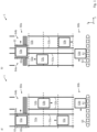
- FIG. 1 shows parts of an elevator system 1 according to the invention.
- the elevator system 1 comprises fixed guide rails 52, along which cabins 53 can be guided in a vertical direction.
- First vertical guide rails 52a are arranged in a first shaft 51a and second guide rails 52b are arranged in a second shaft 51b.
- the elevator system comprises a plurality of cabins 53a, 53b, 53c, 53d, whereby in one shaft in particular more than two cabins can travel simultaneously.
- the elevator system 1 comprises several transfer arrangements 60a, 60b. Using such a transfer arrangement 60, a cabin can be transferred from one shaft to the other shaft.
- a transfer process of the cabin 53a from the first shaft 51a to the second shaft 51b is considered using the upper transfer arrangement 60a.
- the cabin 53a moves vertically along the vertical guide rails 52a into the transfer arrangement 60a.
- the cabin 53a is now in the first transfer position 64a.
- the cabin 53 could, on the one hand, continue vertically to the next floor along the vertical guide rails 52a.
- the cabin 53a can also be transferred to a second transfer position 64b, in which the cabin is then arranged in the second shaft 51b.
- the transfer arrangement 60a has a transfer frame 61 as a transfer support, which is also located in the first transfer position 64a. If both the transfer frame 61 and the cabin 53a are in the first transfer position 64a, the transfer frame 61 can accommodate the cabin 53a.
- a rail section 62 of the vertical guide rail 52 can be separated from the rest of the guide rail 52 and is firmly connected to the transfer frame 61.
- the cabin 53a now enters the guide area of the rail section 62.
- the transfer frame 61 is now moved horizontally, this rail section 62, together with the cabin 53 guided on the rail section 62, moves together with the transfer frame 61.
- the transfer frame 61 is now displaced from the first transfer position 64a to the second transfer position 64b along a transfer track 63.
- the transfer track 63 can be a horizontal rail on which the transfer frame 61 is guided. This transfer principle is basically in the EP 3 318 526 A1 described.
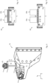
- FIG. 3 shows an exemplary adjustment device 70 in a possible embodiment.
- the adjustment device 70 comprises an adjustment base 71, which can be fastened in a predetermined position, e.g. on the shaft wall 54.
- An adjustment support 72 is fastened to the transfer track 63 in a predetermined position.
- the adjustment support 72 can also be an integral part of the transfer track 63.
- the relative position of the adjustment support 72 with respect to the respective adjustment base 71 defines the position of the transfer track, at least locally.
- An adjustment rail 73 is held on the adjustment base 71 so that it can be moved in the y-direction.
- An adjustment slide 74 is held on the adjustment rail 73 so that it can be moved in a direction x.
- An adjustment screw 75 is placed on top of the adjustment slide 74. The adjustment screw 75 is guided through a threaded hole in the adjustment support 72.
- the directions of the individual adjustment means do not necessarily have to correlate with the spatial directions x, y, z.
- the displaceability can be achieved by a dovetail guide, as shown at the connection between the adjustment rail 73 and the adjustment slide 74.
- a dovetail guide is also present between the adjustment base 71 and the adjustment rail 73, but is not visible in this illustration.
- the transfer arrangement may also comprise a conveyor belt arrangement 60b, such as Figure 5 illustrated.
- Conveyor belt arrangement 60b comprises a conveyor belt 66, wherein the car 52d to be transferred is placed on this conveyor belt.
- the area of the conveyor belt on which the cabin is mounted is regarded as the transfer support 61.
- the conveyor belt 66 and thus the transfer support 61 are guided by means of bearing rollers 67.
- the transfer track 63 is determined by the arrangement and alignment of the bearing rollers.
- the bearing rollers are aligned by the adjustment arrangement 7, analogously to the previous embodiment.
- the transfer positions 64a, 64b are thus set.
- the adjustment can be carried out once during commissioning. Continuous adjustment is not necessary during operation.
- the correct alignment can be checked during regular maintenance work.
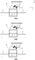
- FIG. 2 shows the transfer carrier is guided by a roller guide 65 on the transfer track 63.
- the transfer track can be formed by a horizontal rail, whereby such a rail can also be present on the other side.
- the transfer track 63 is held on the shaft wall 54 by several adjustment devices 70 (see also Figure 4 ).
- FIG. 2a shows the transfer carrier in 61 together with the cabin 53a in the second, not yet aligned transfer position 64b. It can be seen that the rail section 62, which together with the cabin 53a from the first transfer position to the second transfer position is not aligned with the vertical guide rail 52b in the second shaft.
- the adjustment device 70b the position of the transfer track 63 in the area of the second transfer position 64b is changed initially in the z direction ( Figure 2b ) and then in the x direction. The rail section 62 is then aligned, at least in side view, with the vertical guide rail 52 in the second transfer position 64b.
- Alignment in the position in the X direction can be carried out using a stop (not shown), which can also be part of the adjustment arrangement.
- the stop can be used to define the travel path of the transfer carrier 61 along the track 63.
- the cabin 53 can now move vertically in the second shaft.
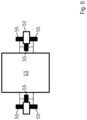
- Figure 7 shows the mounting of the cabin during vertical travel.
- the cabin is guided by guide rollers on the at least two vertical guide rails.
- the at least two vertical guide rails are arranged on opposite sides of the cabin.
Landscapes
- Engineering & Computer Science (AREA)
- Automation & Control Theory (AREA)
- Structural Engineering (AREA)
- Lift-Guide Devices, And Elevator Ropes And Cables (AREA)
- Elevator Control (AREA)
Claims (15)
- Installation d'ascenseur (1), comprenant- au moins une première et une deuxième cage (51a, 51b),- au moins un premier rail de guidage vertical (52a), qui est maintenu dans la première cage (51a),- au moins un deuxième rail de guidage vertical (52b), qui est maintenu dans la deuxième cage (51b),- une pluralité de cabines (53) qui peuvent être déplacées dans les cages (51) le long des rails de guidage verticaux (52),- au moins un agencement de transfert (60) qui est adapté pour transférer les cabines (53) de la première cage (51a) dans la deuxième cage (51b),l'agencement de transfert (60) étant adapté pour transférer la cabine le long d'une voie de transfert (63) entre une première position de transfert (64b) dans la première cage (51a) et une deuxième position de transfert (64b) dans la deuxième cage (51b) dans une direction de transfert (y) le long de la voie de transfert (63),l'agencement de transfert (60) présentant un support de transfert (61) qui peut être transféré le long de la voie de transfert (63) entre la première position de transfert (64a) et la deuxième position de transfert (64b), caractérisé parun agencement de réglage (7) qui est adapté pour régler la position de la première et/ou de la deuxième position de transfert (64) au moins transversalement à la direction de transfert (y).
- Installation d'ascenseur (1) selon la revendication précédente,
caractérisée en ce que
l'agencement de réglage (7) est adapté pour régler la position de la première et/ou de la deuxième position de transfert (64) au moins horizontalement transversalement (x) et/ou verticalement transversalement (z) à la direction de transfert (y). - Installation d'ascenseur (1) selon l'une quelconque des revendications précédentes,
caractérisée en ce que
l'agencement de réglage (7) est adapté pour régler la position de la voie de transfert (63) dans la zone de la première et/ou de la deuxième position de transfert (64) au moins transversalement, notamment horizontalement transversalement (x) et/ou verticalement transversalement (z), à la direction de transfert (y). - Installation d'ascenseur (1) selon l'une quelconque des revendications précédentes,
caractérisée en ce quele support de transfert (61) est adaptépour recevoir la cabine (53) dans la première position de transfert (64a),pour se déplacer avec la cabine (53) de la première position de transfert (64a) à la deuxième position de transfert (64b) etpour libérer à nouveau la cabine (53) dans la deuxième position de transfert (64b). - Installation d'ascenseur (1) selon l'une quelconque des revendications précédentes,
caractérisée en ce que
le support de transfert (61) est un châssis de transfert (61) . - Installation d'ascenseur (1) selon l'une quelconque des revendications précédentes,
caractérisée en ce que
le support de transfert (61) est formé par une section d'une bande transporteuse (66). - Installation d'ascenseur (1) selon l'une quelconque des revendications précédentes,
caractérisée en ce que
l'installation d'ascenseur (1) est adaptée pour qu'une section de rail (62) du rail de guidage vertical (52) soit retirée de la première position de transfert (64a) pendant l'opération de transfert. - Installation d'ascenseur (1) selon l'une quelconque des revendications précédentes,
caractérisée en ce que
la section de rail (62) est transféré avec la cabine (53) de la première position de transfert à la deuxième position de transfert. - Installation d'ascenseur (1) selon l'une quelconque des revendications précédentes,
caractérisée en ce que
la section de rail (62) est montée de manière fixe sur le support de transfert (61). - Installation d'ascenseur (1) selon l'une quelconque des revendications précédentes,
caractérisée en ce que
l'agencement de réglage (7) comprend une pluralité de dispositifs de réglage (70). - Installation d'ascenseur (1) selon la revendication précédente,
caractérisée en ce que
le dispositif de réglage (70) comprend un support de réglage (72) monté sur l'agencement de transfert (60) et une base de réglage (71) fixée dans la cage (51), la position relative du support de réglage (72) par rapport à la base de réglage (71) étant réglable selon au moins deux degrés de liberté latéraux (x, z), notamment trois degrés de liberté latéraux (x, y, z). - Installation d'ascenseur (1) selon l'une quelconque des revendications précédentes,
caractérisée en ce que
la cabine (53) peut être guidée à l'aide de galets de guidage (55) sur au moins deux rails de guidage verticaux (52), les au moins deux rails de guidage verticaux (52) étant agencés sur des côtés opposés de la cabine (53). - Installation d'ascenseur (1) selon l'une quelconque des revendications précédentes,
caractérisée en ce que
l'agencement de transfert (60) ne présente pas de segments de rail rotatifs. - Procédé d'assemblage d'une installation d'ascenseur selon l'une quelconque des revendications précédentes, comprenant les étapes de procédé suivantes :- la fixation de l'agencement de transfert (60) dans les cages (51) ;- ensuite, le réglage des positions de transfert (64a, 64b) à l'aide de l'agencement de réglage (7).
- Procédé selon la revendication précédente, dans lequel le réglage des positions de transfert est effectué par réglage de la voie de transfert (63).
Applications Claiming Priority (2)
| Application Number | Priority Date | Filing Date | Title |
|---|---|---|---|
| DE102018213760.9A DE102018213760A1 (de) | 2018-08-15 | 2018-08-15 | Aufzugsanlage |
| PCT/EP2019/071313 WO2020035388A1 (fr) | 2018-08-15 | 2019-08-08 | Système d'ascenseur |
Publications (2)
| Publication Number | Publication Date |
|---|---|
| EP3837204A1 EP3837204A1 (fr) | 2021-06-23 |
| EP3837204B1 true EP3837204B1 (fr) | 2024-10-02 |
Family
ID=67614570
Family Applications (1)
| Application Number | Title | Priority Date | Filing Date |
|---|---|---|---|
| EP19752686.6A Active EP3837204B1 (fr) | 2018-08-15 | 2019-08-08 | Système d'ascenseur |
Country Status (6)
| Country | Link |
|---|---|
| US (1) | US12459785B2 (fr) |
| EP (1) | EP3837204B1 (fr) |
| CN (2) | CN112566862A (fr) |
| DE (1) | DE102018213760A1 (fr) |
| FI (1) | FI3837204T3 (fr) |
| WO (1) | WO2020035388A1 (fr) |
Families Citing this family (3)
| Publication number | Priority date | Publication date | Assignee | Title |
|---|---|---|---|---|
| DE102020205501A1 (de) | 2020-04-30 | 2021-11-04 | Thyssenkrupp Elevator Innovation And Operations Ag | Verfahren zur Montage von Schienen in einer Aufzugsanlage |
| DE102020205909A1 (de) | 2020-05-12 | 2021-11-18 | Thyssenkrupp Elevator Innovation And Operations Ag | Umsetzanordnung für eine Aufzugsanlage |
| US20220055865A1 (en) * | 2020-08-21 | 2022-02-24 | Otis Elevator Company | Autonomous elevator car mover configured with guide wheels |
Citations (2)
| Publication number | Priority date | Publication date | Assignee | Title |
|---|---|---|---|---|
| WO2017001332A1 (fr) * | 2015-06-30 | 2017-01-05 | Thyssenkrupp Elevator Ag | Élément de support destiné à retenir un dispositif de fixation de rail de guidage d'un système d'ascenseur |
| EP3583061B1 (fr) * | 2017-02-15 | 2020-12-02 | thyssenkrupp Elevator Innovation and Operations AG | Dispositif de retenue |
Family Cites Families (14)
| Publication number | Priority date | Publication date | Assignee | Title |
|---|---|---|---|---|
| JP2529761B2 (ja) | 1990-07-02 | 1996-09-04 | 三菱電機株式会社 | エレベ―タ装置 |
| JPH05310384A (ja) * | 1991-11-01 | 1993-11-22 | Toshiba Corp | エレベータ |
| JP2788366B2 (ja) * | 1991-11-07 | 1998-08-20 | 株式会社東芝 | エレベータ |
| EP2070860A1 (fr) * | 2007-12-11 | 2009-06-17 | Inventio Ag | Système d'ascenseur doté de cabines d'ascenseur mobiles verticalement et horizontalement |
| EP2161233B1 (fr) * | 2008-09-01 | 2012-02-01 | ThyssenKrupp Elevator AG | Dispositif de transport destiné à transférer la cabine d'un ascenseur |
| GB2504907B (en) * | 2011-05-11 | 2016-11-02 | Otis Elevator Co | Circulation transport system |
| CN107108163B (zh) * | 2014-12-30 | 2019-12-03 | 奥的斯电梯公司 | 用于无绳电梯系统的具有子部件和驻停区的冗余的传送站 |
| CN106395552B (zh) | 2015-08-03 | 2020-03-17 | 奥的斯电梯公司 | 无绳电梯系统导轨组件 |
| CN108059062B (zh) * | 2016-11-07 | 2020-05-26 | 奥的斯电梯公司 | 模块化调转站 |
| DE102016222837A1 (de) * | 2016-11-21 | 2018-05-24 | Thyssenkrupp Ag | Verfahren zum Betreiben einer Aufzugsanlage |
| CN106927336A (zh) * | 2017-03-22 | 2017-07-07 | 山东建筑大学 | 一种面向双井道可水平和垂直运行的电梯 |
| CN107458947A (zh) * | 2017-07-31 | 2017-12-12 | 江苏速升自动化装备股份有限公司 | 一种轿厢能平移的电梯 |
| CN108313855B (zh) * | 2018-04-11 | 2023-06-30 | 河南理工大学 | 一种多轿厢立体循环电梯系统及协同运行方法 |
| KR102422889B1 (ko) * | 2020-09-03 | 2022-07-21 | 현대무벡스 주식회사 | 수직 이송 시스템 |
-
2018
- 2018-08-15 DE DE102018213760.9A patent/DE102018213760A1/de not_active Ceased
-
2019
- 2019-08-08 CN CN201980054227.5A patent/CN112566862A/zh active Pending
- 2019-08-08 US US17/250,641 patent/US12459785B2/en active Active
- 2019-08-08 WO PCT/EP2019/071313 patent/WO2020035388A1/fr not_active Ceased
- 2019-08-08 CN CN202511663636.9A patent/CN121553796A/zh active Pending
- 2019-08-08 EP EP19752686.6A patent/EP3837204B1/fr active Active
- 2019-08-08 FI FIEP19752686.6T patent/FI3837204T3/fi active
Patent Citations (2)
| Publication number | Priority date | Publication date | Assignee | Title |
|---|---|---|---|---|
| WO2017001332A1 (fr) * | 2015-06-30 | 2017-01-05 | Thyssenkrupp Elevator Ag | Élément de support destiné à retenir un dispositif de fixation de rail de guidage d'un système d'ascenseur |
| EP3583061B1 (fr) * | 2017-02-15 | 2020-12-02 | thyssenkrupp Elevator Innovation and Operations AG | Dispositif de retenue |
Also Published As
| Publication number | Publication date |
|---|---|
| CN121553796A (zh) | 2026-02-24 |
| US12459785B2 (en) | 2025-11-04 |
| EP3837204A1 (fr) | 2021-06-23 |
| US20210171319A1 (en) | 2021-06-10 |
| FI3837204T3 (fi) | 2024-12-27 |
| CN112566862A (zh) | 2021-03-26 |
| WO2020035388A1 (fr) | 2020-02-20 |
| DE102018213760A1 (de) | 2020-02-20 |
Similar Documents
| Publication | Publication Date | Title |
|---|---|---|
| EP1609532B1 (fr) | Installation de peinture et procédé de fonctionnement | |
| EP3837204B1 (fr) | Système d'ascenseur | |
| DE69418169T2 (de) | Verfahren und Vorrichtung für die Montage eines Geländers von Rolltreppen oder Fahrsteigen | |
| EP3212556B1 (fr) | Procédé d'installation de rails de guidage | |
| DE202014006420U1 (de) | Transfermodul, Montagemodul und Umsetzmodul für ein modulares Montage-Transfersystem sowie modulares Montage-Transfersystem | |
| EP3658462B1 (fr) | Installation d'usinage pour éléments structuraux d'avions | |
| WO2020193186A2 (fr) | Dispositif d'alignement et procédé d'alignement d'un rail de guidage d'une installation d'ascenseur | |
| EP3052420B1 (fr) | Installation d'ascenseur | |
| EP2006453B1 (fr) | Cadre d'étayage en U | |
| EP4031729B1 (fr) | Dispositif imprimante permettant de produire une structure de béton d'une installation de transport de personnes | |
| WO2019197201A1 (fr) | Procédé de montage de rails dans un système d'ascenseur | |
| EP2677094B1 (fr) | Tourelle d'un monte-personnes | |
| DE29502449U1 (de) | Ortsveränderliche Montagestation | |
| DE69015461T2 (de) | Fliessband für Unterhalt und Reparatur von Fahrzeug-Aufbauten. | |
| EP3081522A1 (fr) | Escalier doté de rails de retour communs | |
| DE102004015152B4 (de) | Eigenfortbewegungsfähige Vorrichtung für Gebäudefassaden | |
| EP3924285B1 (fr) | Système d'ascenseur | |
| DE9400343U1 (de) | Bodenfördersystem | |
| AT519207A1 (de) | Fördereinrichtung zum Fördern von Produkten | |
| EP3575031A1 (fr) | Dispositif d'usinage ainsi que procédé de montage du dispositif d'usinage | |
| EP4540163B1 (fr) | Module de cage destiné à la formation d'une cage d'ascenseur composée de modules de cage superposés les uns sur les autres pour une installation d'ascenseur | |
| DE102017200864B4 (de) | Hubvorrichtung zum Heben von Komponenten | |
| WO2026037657A1 (fr) | Procédé de construction d'une cage d'ascenseur composée de modules d'arbre placés les uns sur les autres | |
| DE10211215A1 (de) | Anlage zum beidseitigen Behandeln, insbesondere zum beidseitigen Pulverlackieren, von Blechzuschnitten | |
| WO2018073318A1 (fr) | Procédé de montage et dispositif de montage |
Legal Events
| Date | Code | Title | Description |
|---|---|---|---|
| STAA | Information on the status of an ep patent application or granted ep patent |
Free format text: STATUS: UNKNOWN |
|
| STAA | Information on the status of an ep patent application or granted ep patent |
Free format text: STATUS: THE INTERNATIONAL PUBLICATION HAS BEEN MADE |
|
| PUAI | Public reference made under article 153(3) epc to a published international application that has entered the european phase |
Free format text: ORIGINAL CODE: 0009012 |
|
| STAA | Information on the status of an ep patent application or granted ep patent |
Free format text: STATUS: REQUEST FOR EXAMINATION WAS MADE |
|
| 17P | Request for examination filed |
Effective date: 20210212 |
|
| AK | Designated contracting states |
Kind code of ref document: A1 Designated state(s): AL AT BE BG CH CY CZ DE DK EE ES FI FR GB GR HR HU IE IS IT LI LT LU LV MC MK MT NL NO PL PT RO RS SE SI SK SM TR |
|
| DAV | Request for validation of the european patent (deleted) | ||
| DAX | Request for extension of the european patent (deleted) | ||
| STAA | Information on the status of an ep patent application or granted ep patent |
Free format text: STATUS: EXAMINATION IS IN PROGRESS |
|
| 17Q | First examination report despatched |
Effective date: 20221019 |
|
| GRAP | Despatch of communication of intention to grant a patent |
Free format text: ORIGINAL CODE: EPIDOSNIGR1 |
|
| STAA | Information on the status of an ep patent application or granted ep patent |
Free format text: STATUS: GRANT OF PATENT IS INTENDED |
|
| INTG | Intention to grant announced |
Effective date: 20240318 |
|
| RAP3 | Party data changed (applicant data changed or rights of an application transferred) |
Owner name: TK ELEVATOR INNOVATION AND OPERATIONS GMBH |
|
| GRAS | Grant fee paid |
Free format text: ORIGINAL CODE: EPIDOSNIGR3 |
|
| P01 | Opt-out of the competence of the unified patent court (upc) registered |
Free format text: CASE NUMBER: APP_40247/2024 Effective date: 20240705 |
|
| GRAA | (expected) grant |
Free format text: ORIGINAL CODE: 0009210 |
|
| STAA | Information on the status of an ep patent application or granted ep patent |
Free format text: STATUS: THE PATENT HAS BEEN GRANTED |
|
| AK | Designated contracting states |
Kind code of ref document: B1 Designated state(s): AL AT BE BG CH CY CZ DE DK EE ES FI FR GB GR HR HU IE IS IT LI LT LU LV MC MK MT NL NO PL PT RO RS SE SI SK SM TR |
|
| REG | Reference to a national code |
Ref country code: GB Ref legal event code: FG4D Free format text: NOT ENGLISH |
|
| REG | Reference to a national code |
Ref country code: CH Ref legal event code: EP |
|
| REG | Reference to a national code |
Ref country code: DE Ref legal event code: R096 Ref document number: 502019012228 Country of ref document: DE |
|
| REG | Reference to a national code |
Ref country code: IE Ref legal event code: FG4D Free format text: LANGUAGE OF EP DOCUMENT: GERMAN |
|
| REG | Reference to a national code |
Ref country code: FI Ref legal event code: FGE |
|
| REG | Reference to a national code |
Ref country code: LT Ref legal event code: MG9D |
|
| REG | Reference to a national code |
Ref country code: NL Ref legal event code: MP Effective date: 20241002 |
|
| PG25 | Lapsed in a contracting state [announced via postgrant information from national office to epo] |
Ref country code: NL Free format text: LAPSE BECAUSE OF FAILURE TO SUBMIT A TRANSLATION OF THE DESCRIPTION OR TO PAY THE FEE WITHIN THE PRESCRIBED TIME-LIMIT Effective date: 20241002 |
|
| PG25 | Lapsed in a contracting state [announced via postgrant information from national office to epo] |
Ref country code: NL Free format text: LAPSE BECAUSE OF FAILURE TO SUBMIT A TRANSLATION OF THE DESCRIPTION OR TO PAY THE FEE WITHIN THE PRESCRIBED TIME-LIMIT Effective date: 20241002 |
|
| PG25 | Lapsed in a contracting state [announced via postgrant information from national office to epo] |
Ref country code: IS Free format text: LAPSE BECAUSE OF FAILURE TO SUBMIT A TRANSLATION OF THE DESCRIPTION OR TO PAY THE FEE WITHIN THE PRESCRIBED TIME-LIMIT Effective date: 20250202 Ref country code: PT Free format text: LAPSE BECAUSE OF FAILURE TO SUBMIT A TRANSLATION OF THE DESCRIPTION OR TO PAY THE FEE WITHIN THE PRESCRIBED TIME-LIMIT Effective date: 20250203 Ref country code: HR Free format text: LAPSE BECAUSE OF FAILURE TO SUBMIT A TRANSLATION OF THE DESCRIPTION OR TO PAY THE FEE WITHIN THE PRESCRIBED TIME-LIMIT Effective date: 20241002 |
|
| PG25 | Lapsed in a contracting state [announced via postgrant information from national office to epo] |
Ref country code: BG Free format text: LAPSE BECAUSE OF FAILURE TO SUBMIT A TRANSLATION OF THE DESCRIPTION OR TO PAY THE FEE WITHIN THE PRESCRIBED TIME-LIMIT Effective date: 20241002 |
|
| PG25 | Lapsed in a contracting state [announced via postgrant information from national office to epo] |
Ref country code: ES Free format text: LAPSE BECAUSE OF FAILURE TO SUBMIT A TRANSLATION OF THE DESCRIPTION OR TO PAY THE FEE WITHIN THE PRESCRIBED TIME-LIMIT Effective date: 20241002 |
|
| PG25 | Lapsed in a contracting state [announced via postgrant information from national office to epo] |
Ref country code: NO Free format text: LAPSE BECAUSE OF FAILURE TO SUBMIT A TRANSLATION OF THE DESCRIPTION OR TO PAY THE FEE WITHIN THE PRESCRIBED TIME-LIMIT Effective date: 20250102 |
|
| PG25 | Lapsed in a contracting state [announced via postgrant information from national office to epo] |
Ref country code: LV Free format text: LAPSE BECAUSE OF FAILURE TO SUBMIT A TRANSLATION OF THE DESCRIPTION OR TO PAY THE FEE WITHIN THE PRESCRIBED TIME-LIMIT Effective date: 20241002 Ref country code: GR Free format text: LAPSE BECAUSE OF FAILURE TO SUBMIT A TRANSLATION OF THE DESCRIPTION OR TO PAY THE FEE WITHIN THE PRESCRIBED TIME-LIMIT Effective date: 20250103 |
|
| PG25 | Lapsed in a contracting state [announced via postgrant information from national office to epo] |
Ref country code: PL Free format text: LAPSE BECAUSE OF FAILURE TO SUBMIT A TRANSLATION OF THE DESCRIPTION OR TO PAY THE FEE WITHIN THE PRESCRIBED TIME-LIMIT Effective date: 20241002 Ref country code: CZ Free format text: LAPSE BECAUSE OF FAILURE TO SUBMIT A TRANSLATION OF THE DESCRIPTION OR TO PAY THE FEE WITHIN THE PRESCRIBED TIME-LIMIT Effective date: 20241002 |
|
| PG25 | Lapsed in a contracting state [announced via postgrant information from national office to epo] |
Ref country code: RS Free format text: LAPSE BECAUSE OF FAILURE TO SUBMIT A TRANSLATION OF THE DESCRIPTION OR TO PAY THE FEE WITHIN THE PRESCRIBED TIME-LIMIT Effective date: 20250102 |
|
| PG25 | Lapsed in a contracting state [announced via postgrant information from national office to epo] |
Ref country code: SM Free format text: LAPSE BECAUSE OF FAILURE TO SUBMIT A TRANSLATION OF THE DESCRIPTION OR TO PAY THE FEE WITHIN THE PRESCRIBED TIME-LIMIT Effective date: 20241002 |
|
| REG | Reference to a national code |
Ref country code: DE Ref legal event code: R097 Ref document number: 502019012228 Country of ref document: DE |
|
| PG25 | Lapsed in a contracting state [announced via postgrant information from national office to epo] |
Ref country code: DK Free format text: LAPSE BECAUSE OF FAILURE TO SUBMIT A TRANSLATION OF THE DESCRIPTION OR TO PAY THE FEE WITHIN THE PRESCRIBED TIME-LIMIT Effective date: 20241002 |
|
| PG25 | Lapsed in a contracting state [announced via postgrant information from national office to epo] |
Ref country code: EE Free format text: LAPSE BECAUSE OF FAILURE TO SUBMIT A TRANSLATION OF THE DESCRIPTION OR TO PAY THE FEE WITHIN THE PRESCRIBED TIME-LIMIT Effective date: 20241002 |
|
| PG25 | Lapsed in a contracting state [announced via postgrant information from national office to epo] |
Ref country code: RO Free format text: LAPSE BECAUSE OF FAILURE TO SUBMIT A TRANSLATION OF THE DESCRIPTION OR TO PAY THE FEE WITHIN THE PRESCRIBED TIME-LIMIT Effective date: 20241002 |
|
| PG25 | Lapsed in a contracting state [announced via postgrant information from national office to epo] |
Ref country code: SK Free format text: LAPSE BECAUSE OF FAILURE TO SUBMIT A TRANSLATION OF THE DESCRIPTION OR TO PAY THE FEE WITHIN THE PRESCRIBED TIME-LIMIT Effective date: 20241002 |
|
| PG25 | Lapsed in a contracting state [announced via postgrant information from national office to epo] |
Ref country code: IT Free format text: LAPSE BECAUSE OF FAILURE TO SUBMIT A TRANSLATION OF THE DESCRIPTION OR TO PAY THE FEE WITHIN THE PRESCRIBED TIME-LIMIT Effective date: 20241002 |
|
| PLBE | No opposition filed within time limit |
Free format text: ORIGINAL CODE: 0009261 |
|
| STAA | Information on the status of an ep patent application or granted ep patent |
Free format text: STATUS: NO OPPOSITION FILED WITHIN TIME LIMIT |
|
| PG25 | Lapsed in a contracting state [announced via postgrant information from national office to epo] |
Ref country code: SE Free format text: LAPSE BECAUSE OF FAILURE TO SUBMIT A TRANSLATION OF THE DESCRIPTION OR TO PAY THE FEE WITHIN THE PRESCRIBED TIME-LIMIT Effective date: 20241002 |
|
| 26N | No opposition filed |
Effective date: 20250703 |
|
| PGFP | Annual fee paid to national office [announced via postgrant information from national office to epo] |
Ref country code: FI Payment date: 20250822 Year of fee payment: 7 |
|
| PGFP | Annual fee paid to national office [announced via postgrant information from national office to epo] |
Ref country code: DE Payment date: 20250820 Year of fee payment: 7 |
|
| PGFP | Annual fee paid to national office [announced via postgrant information from national office to epo] |
Ref country code: CH Payment date: 20250901 Year of fee payment: 7 |
|
| PG25 | Lapsed in a contracting state [announced via postgrant information from national office to epo] |
Ref country code: MC Free format text: LAPSE BECAUSE OF FAILURE TO SUBMIT A TRANSLATION OF THE DESCRIPTION OR TO PAY THE FEE WITHIN THE PRESCRIBED TIME-LIMIT Effective date: 20241002 |
|
| PG25 | Lapsed in a contracting state [announced via postgrant information from national office to epo] |
Ref country code: LU Free format text: LAPSE BECAUSE OF NON-PAYMENT OF DUE FEES Effective date: 20250808 |