EP3839158A1 - Bac sanitaire, en particulier receveur de douche - Google Patents
Bac sanitaire, en particulier receveur de douche Download PDFInfo
- Publication number
- EP3839158A1 EP3839158A1 EP20213057.1A EP20213057A EP3839158A1 EP 3839158 A1 EP3839158 A1 EP 3839158A1 EP 20213057 A EP20213057 A EP 20213057A EP 3839158 A1 EP3839158 A1 EP 3839158A1
- Authority
- EP
- European Patent Office
- Prior art keywords
- flange
- drain
- tub
- range
- underside
- Prior art date
- Legal status (The legal status is an assumption and is not a legal conclusion. Google has not performed a legal analysis and makes no representation as to the accuracy of the status listed.)
- Granted
Links
Images








Classifications
-
- E—FIXED CONSTRUCTIONS
- E03—WATER SUPPLY; SEWERAGE
- E03F—SEWERS; CESSPOOLS
- E03F5/00—Sewerage structures
- E03F5/04—Gullies inlets, road sinks, floor drains with or without odour seals or sediment traps
- E03F5/0407—Floor drains for indoor use
- E03F5/0408—Floor drains for indoor use specially adapted for showers
-
- A—HUMAN NECESSITIES
- A47—FURNITURE; DOMESTIC ARTICLES OR APPLIANCES; COFFEE MILLS; SPICE MILLS; SUCTION CLEANERS IN GENERAL
- A47K—SANITARY EQUIPMENT; ACCESSORIES THEREFOR, e.g. TOILET ACCESSORIES
- A47K3/00—Baths; Showers; Appurtenances therefor
- A47K3/28—Showers or bathing douches
- A47K3/40—Pans or trays
-
- E—FIXED CONSTRUCTIONS
- E03—WATER SUPPLY; SEWERAGE
- E03C—DOMESTIC PLUMBING INSTALLATIONS FOR FRESH WATER OR WASTE WATER; SINKS
- E03C1/00—Domestic plumbing installations for fresh water or waste water; Sinks
- E03C1/12—Plumbing installations for waste water; Basins or fountains connected thereto; Sinks
- E03C1/22—Outlet devices mounted in basins, baths, or sinks
-
- E—FIXED CONSTRUCTIONS
- E03—WATER SUPPLY; SEWERAGE
- E03C—DOMESTIC PLUMBING INSTALLATIONS FOR FRESH WATER OR WASTE WATER; SINKS
- E03C1/00—Domestic plumbing installations for fresh water or waste water; Sinks
- E03C1/12—Plumbing installations for waste water; Basins or fountains connected thereto; Sinks
- E03C1/26—Object-catching inserts or similar devices for waste pipes or outlets
-
- E—FIXED CONSTRUCTIONS
- E03—WATER SUPPLY; SEWERAGE
- E03F—SEWERS; CESSPOOLS
- E03F5/00—Sewerage structures
- E03F5/04—Gullies inlets, road sinks, floor drains with or without odour seals or sediment traps
- E03F5/0407—Floor drains for indoor use
- E03F5/0409—Devices for preventing seepage around the floor drain
Definitions
- the invention relates to a sanitary tub, in particular a shower tray, preferably made of steel enamel, with a base, a drain opening formed in the base and an annular flange produced separately from the tub, which defines a connection surface and on the underside of the base of the tub is arranged and surrounds the drain opening.
- a sanitary tub is to be understood as meaning, for example, a bathtub or a deep or flat shower tub, the latter also being able to be referred to as a shower tray.
- a shower tray is also understood here to mean those shower trays that are designed to be particularly flat, in particular those that do not have an upwardly protruding shower tray edge on their circumference.
- Conventional bathtubs and shower trays are made of steel enamel or fiber-reinforced plastic and have a trough or surrounding recess in the edge area of their drainage opening (see e.g. DE 10 2006 030 481 A1 ).
- the surrounding recess is used to fix a drain fitting by means of a connecting counterpart in the form of a flange.
- the circumferential recess is produced by reshaping, usually by embossing the edge area of the drainage opening of the bathtub or shower tray. After reshaping the sheet steel and cutting it out, e.g. B. punching out the drain opening - and possibly cutting out an overflow opening - the tub or shower tray body is enamelled.
- the invention is based on the object of creating a sanitary tub, in particular a shower tray of the type mentioned, which differs from conventional bathtubs and shower trays in terms of the shape in the area of the drain opening and yet has a liquid-tight connection of a drain fitting to the drain opening of the Tub allows.
- the tub according to the invention which can be designed in particular in the form of a flat shower tray, is characterized in that the flange is connected to the bottom of the tub in a liquid-tight manner without a connecting counterpart, for example a fastening flange, resting on the top of the bottom of the tub, and that the Flange which defines a connection surface and is arranged on the underside of the bottom of the tub and surrounds the drain opening, is connected to a drain housing of a drain fitting or is prepared for a detachable connection to a drain housing of a drain fitting.
- a connecting counterpart for example a fastening flange
- the present invention is based on the idea of design parts of a bathtub or shower tray, in particular one made of steel enamel, in the area of the drain opening to be produced by flat components or floor sections without a high degree of deformation. All or almost all functional parts in the area of the drainage opening should be arranged in the non-visible area under the cover (drainage hood) and thus hidden.
- An advantageous embodiment of the tub according to the invention, in particular the shower tray, is characterized in that the tub preferably has no circumferential embossing in an edge area surrounding the drain opening in a ring shape, which extends away from the drain opening, this edge area having a circumferential or radial edge width in the range from 10 mm to 80 mm, preferably in the range from 50 mm to 80 mm.
- no small bending radii, in particular no S-shaped bending contours are formed in the said edge area.
- this edge area directly adjoining the drain opening which has a circumferential or radial edge width in the range from 10 mm to 80 mm, preferably in the range from 50 mm to 80 mm, is essentially designed without a circumferential embossing and thus particularly flat.
- the tub in particular the shower tray, is thus largely or largely flat in the edge region of the drain opening.
- the drain opening can be produced by cutting the tub bottom in the area of a provided floor drain using lasers, punching or similar cutting processes, without plastically reshaping the tub bottom in the edge region of the drain opening.
- the depth of this minimal circumferential embossing is, for example, in the range from 2 mm to 20 mm, preferably in the range from 2 mm to 15 mm, particularly preferably in the range from 2 mm to 10 mm.
- the drain opening of the tub according to the invention is preferably delimited by a perforated edge which has an edge radius in the range from 0.25 mm to 2.5 mm, preferably in the range from 1.0 mm to 2.0 mm.
- the flange can also be referred to as an adapter flange.
- the flange is positively, cohesively or non-positively connected to the tub.
- Another advantageous embodiment of the invention is characterized in that the flange is glued to its connection surface with the underside of the tub.
- Such a material connection can be implemented cost-effectively in terms of production technology.
- the adhesive connection enables a liquid-tight connection of the flange to the tub at the same time.
- the underside of the bottom of the tub is provided with pin-shaped or bolt-shaped fastening means, the flange having a plurality of through holes for receiving the fastening means in the region of its connection surface.
- the fastening means can be designed, for example, as screw bolts connected to the underside of the tub bottom.
- the fastening means can also be locking bolts.
- a sealing ring can be arranged between the tank bottom and the flange. It is also possible to combine this non-positive connection with the adhesive connection specified above, the adhesive or a double-sided adhesive sealing ring ensuring a liquid-tight connection of the flange to the tub.
- Another advantageous embodiment of the invention is characterized in that the flange has several through holes for anchoring adhesive in the area of its connection surface. In this way, a particularly reliable fixation of the drain fitting on the shower tray or tub can be achieved.
- a further embodiment of the invention consists in that the drain opening is provided with a cover which, together with the drain opening, delimits a circumferential inlet gap, the top of the cover being flush with the top of the edge area surrounding the drain opening.
- the cover hood can also be referred to as a drain hood.
- the cover hood covers an inlet opening of the drain fitting and creates an attractive design. The flush arrangement of the covering hood relative to the surrounding edge area prevents a person using the tub from possibly painfully striking the peripheral edge of the covering hood with a foot.
- the top of the cover (drainage hood) is typically clearly visible to an observer when the drainage fitting is installed and in its intended condition.
- the top of the cover can therefore also be referred to as a decorative top or is designed as a decorative top.
- the decorative top of the cover can be implemented, for example, by a decorative plate arranged on the top of the cover.
- the top of the cover hood or decorative plate can be designed to be essentially flat or slightly curved upward.
- the inlet gap delimited by the tub drain opening and the cover hood has, for example, a gap width in the range from 1.0 to 8 mm, preferably in the range from 1.5 mm to 4 mm, particularly preferably in the range from 1.5 mm to 2.5 mm.
- the drain opening has an inside diameter of at least 130 mm, preferably at least 150 mm, particularly preferably at least 180 mm.
- the inside diameter of the drain opening can also be at least 200 mm.
- An upper limit for the inside diameter of the drain opening can be, for example, 250 mm, 300 mm or 400 mm. However, even larger inner diameters are also conceivable for the drain opening of the tub.
- the cover is preferably arranged such that the perforated edge of the drain opening and the hood edge defined by the cover are butted against each other, delimiting the inlet gap.
- the circumferential inlet gap has an inlet cross-sectional area in the range from approx. 1500 mm 2 to approx. 3500 mm 2 , preferably in the range from approx. 1500 mm 2 to approx 3000 mm 2 , particularly preferably in the range from approx. 1200 mm 2 to approx. 2500 mm 2 , in particular in the range from approx. 1200 mm 2 to approx. 2000 mm 2 .
- a further advantageous embodiment of the invention provides that the cover hood has spacers on its underside, with which it rests on an inlet surface of the flange that is lower relative to the connection surface of the flange. In this way, with a flush arrangement of the cover hood relative to the surrounding edge area of the tub bottom, stable mounting of the cover hood can be achieved in a favorable manner.
- the flange has a horizontal outer dimension which is greater than a horizontal outer dimension of the cover hood that is aligned relative to the outer dimension of the flange.
- the present invention significantly extends the scope for the design of a shower tray, in particular a shower tray made of steel enamel.
- a shower tray designed according to the invention enables a drain fitting to be reliably fixed to the shower tray without a circumferential indentation (embossing) in the edge area of the drain opening of the shower tray.
- the invention offers the possibility of producing design parts in the area of the drain opening of the shower tray using flat components without a high degree of deformation. All functional parts in the area of the drain opening can be arranged in the non-visible area under the cover and thus hidden.
- the horizontal outer dimension of the flange is preferably at least 5%, preferably at least 10%, particularly preferably at least 15% greater than the horizontal outer dimension of the cover hood, which is aligned in the same direction relative to the outer dimension of the flange.
- An upper limit for the horizontal outer dimension of the flange can be, for example, approximately 150% of the rectified, horizontal outer dimension of the cover hood.
- the drain opening of the shower tray and the cover hood are preferably designed to be circular.
- the above-mentioned horizontal external dimension can then also be referred to as the (horizontal) external diameter.
- An advantageous embodiment of the invention is characterized in that the flange and / or the drain housing has an inlet surface lying lower relative to the connection surface of the flange, which surrounds the inlet opening of the drain housing when the drain fitting is installed and is spaced from the underside of the cover hood.
- the cover hood preferably has spacers on its underside, with which it rests on the inlet surface.
- a circumferential annular groove for receiving an annular seal for example an annular elastomer seal
- the annular groove surrounds the inlet surface and is preferably arranged at a relatively small distance from the inlet surface, for example at a distance in the range from approx. 2 mm to 15 mm, in particular in the range from approx. 3 to 10 mm, in the connection surface of the flange.
- a ring seal inserted into the ring groove ensures a reliable liquid seal between the shower tray or tub and drain fitting, especially when the connection surface of the flange is subsequently glued to the underside of the tub or shower tray base.
- this configuration can ensure that the adhesive is effectively sealed off from the water drainage area of the drain fitting, so that shower or bath water cannot get to the adhesive.
- connection surface of the flange is connected in one piece to the inlet surface surrounding the inlet opening of the drain housing via a conical inlet surface.
- the conical inlet surface promotes the drainage of water into the drain housing and prevents dirt from sticking to the inlet surface to a large extent.
- the cover hood can be easily and reliably centered in the drain opening of the tub by means of the conical inlet surface.
- the spacers formed on the underside of the cover preferably have beveled edges on their outer sections, the respective beveled edge defining an angle relative to a horizontal plane which essentially corresponds to the angle of inclination of the conical inlet surface. In other words, the beveled edge of the spacer runs essentially parallel to the contour of the conical inlet surface.
- the inlet surface which is lower relative to the connection surface of the flange, is inclined, preferably conical, towards the inlet opening of the drain housing.
- the inlet surface is limited to the outside by a circumferential shoulder or a circumferential inner wall.
- the inclined, preferably conical inlet surface promotes the drainage of water into the drain housing and prevents dirt from adhering to the inlet surface to a large extent.
- the cover hood can also be easily and reliably centered on the circumferential shoulder or on the circumferential inner wall relative to the drain opening of the tub.
- the cover has on its underside, for example, a plurality of spacers, for example rib-shaped or web-shaped spacers, which protrude radially beyond the outer edge of the cover.
- the outer end faces of the spacers abut against the circumferential shoulder or the circumferential inner wall or end with very little play relative to the shoulder or the inner wall.
- the spacers are preferably designed in such a way that their ends protruding radially over the outer edge of the covering hood or over the outer edge of a carrier of a decorative panel of the covering hood are inclined or stepped towards the outer end face.
- the spacers are barely visible through the inlet gap, which is advantageous for the aesthetic design of the inlet gap.
- this configuration also optimizes the drainage capacity of the drainage fitting with a small width of the inlet gap.
- the cover hood or the decorative plate attached to the carrier preferably has a closed or substantially closed top side.
- a substantially closed top side means a top side that optionally has a single or multiple through openings, the area proportion of the through opening or through openings being a maximum of 2% of the total area of the upper side of the cover hood or decorative panel.
- a further advantageous embodiment of the invention provides that the flange has a multiplicity of projections, the spacers engaging in recesses delimited by the projections.
- the inlet surface is delimited to the outside by a circumferential shoulder or a circumferential inner wall, the shoulder or the wall having a plurality of projections, and the spacers engaging in recesses delimited by the projections.
- This form-fitting connection prevents or blocks rotation of the cover around a vertical axis relative to the flange and the drain housing.
- Another advantageous embodiment of the invention is characterized in that an annular shoulder is formed on the inlet surface for positively receiving a flange section of a fastening flange, in particular a screw flange.
- the transition from the inlet surface to the fastening or screw flange can be made essentially flush with the surface, preferably without an upwardly protruding projection. In this way, deposits at the transition from the inlet surface to the screw flange can be largely prevented.
- the inlet surface surrounding the inlet opening of the drain housing is connected to the drain housing by means of a screw flange.
- This configuration enables the number of components of the drain fitting to be reduced by using only a single screw flange instead of a fastening flange with several fastening screws and a corresponding number of threaded sleeves cast in the drain housing, which is screwed into an internal thread formed on the inlet opening of the drain housing.
- the screw flange preferably has grip elements.
- the screw flange can thus be screwed into the internal thread formed on the inlet opening of the drain housing without tools.
- the handle elements are for example in Form of ribs formed, which are arranged on the inside and / or the top of the screw flange.
- the screw flange has, for example, two, three or four such grip elements (ribs), which are evenly spaced from one another.
- the ribs preferably protrude radially from the inside of the screw flange and each have an end edge which extends downward in an arc shape from the upper end of the respective rib in the direction of the central axis of the screw flange.
- the flange has a plurality of through holes in the area of its connection surface for receiving fastening means connected to the underside of the shower tray or tub or for anchoring adhesive.
- the fastening means connected to the underside of the shower tray or tub can be, for example, screw bolts or locking bolts.
- the horizontal external dimension of the cover is for example at least 130 mm, preferably at least 150 mm, particularly preferably at least 180 mm, in particular at least 200 mm.
- the drainage opening of the tub or shower tray has a slightly larger external dimension than the cover. In this way, a high drainage capacity can be achieved with a relatively narrow inlet gap.
- the cover hood and the drain opening of the shower tray or tub are preferably each circular.
- the then circular inlet gap is ideal in terms of flow technology.
- the cover hood has an enamelled decorative plate on the top.
- the cover hood gives a high-quality impression when installed.
- the Cover hood comprises a carrier, on the upper side of which the decorative plate is arranged and firmly connected to the carrier.
- the carrier which is provided with the above-mentioned spacers on the underside, can be manufactured inexpensively from plastic, for example.
- the enamelled decorative panel has excellent hygienic properties.
- the color of the decorative panel can correspond to the visible surface of the shower tray or tub, so that the shower tray or tub then has an inconspicuous, discreet design in the area of the drain opening.
- the carrier of the cover has on its underside a downwardly tapering liquid guide element, which is preferably designed in the form of a cone, truncated cone, hyperbolic cone or hyperbolic truncated cone, the tip or taper of the liquid guide element preferably into the inlet opening of the drain housing protrudes.
- Another advantageous embodiment of the invention is characterized in that several holes or receptacles for connecting adjustable feet, preferably height-adjustable adjustable feet, are formed on the underside of the flange.
- the floor of the shower tray or bathtub can be optimally supported on an unfinished or screed floor at the installation site using the adjustable feet.
- the flange is detachably connected to the drain housing in the assembled state of the drain fitting.
- This design of the drain fitting is advantageous both in terms of production technology and in terms of assembly technology.
- the hair strainer preferably has a substantially cup-shaped or bowl-shaped shape and has a large number of small through-openings.
- the small through openings are preferably designed in the shape of a gap.
- the hair sieve is this is preferably provided with a handle, preferably a centrally arranged, button-shaped or peg-shaped handle, so that the hair strainer can be easily removed from the inlet opening for cleaning purposes and can be reinserted into the inlet opening after cleaning.
- one or more receptacles for connecting one or more adjustable feet are formed on the underside of the flange.
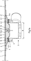
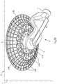
- a section of the bottom 1 of a shower tray D is shown.
- the shower tray D is, for example, a shower tray made of steel enamel.
- the shower tray D has a drain opening 2, which is preferably circular.
- the edge area of the shower tray base surrounding the drain opening has a conical embossing that protrudes downwards compared to the underside of the base, the in Figures 1 to 5
- the partially shown shower tray in the edge region 3 surrounding the drain opening 2 in a ring shape, which extends away from the drain opening 2, has no embossing.
- the top of the shower tray disclosed here is thus essentially flat in an edge region 3 surrounding the drain opening 2, which has a circumferential or radial edge width of at least 50 mm, preferably at least 80 mm.
- the top or the bottom 1 of the shower tray D is, however, preferably slightly inclined in the direction of the drain opening 2, so that water located on the bottom 1 flows off in the direction of the drain opening 2.
- the angle of inclination of the upper side of the shower tray with respect to the horizontal is, for example, in a range from 1 ° to 5 °, preferably in the range from 1 ° to 3 °.
- the drain opening 2 of the shower tray D is produced, for example, by laser cutting or punching.
- the drainage opening 2 is relatively sharp-edged and delimited by a perforated edge 2.1, which has an edge radius in the range from approx. 0.25 mm to 2.5 mm, preferably in the range from approx. 1.0 mm to 2.0 mm.
- the flange 4 is assigned to a drain fitting 5 or part of a drain fitting 5.
- the flange 4 can also be referred to as an adapter flange. It has a connection surface 4.1 intended for arrangement on the underside of the shower tray.
- the flange 4 is designed in such a way that it can be connected to the shower tray D in a liquid-tight manner without a connecting counterpart resting on the top of the shower tray base 1.
- the flange 4 is firmly connected to the shower tray.
- the cohesive connection can be realized, for example, by means of adhesive applied all the way to the ring-shaped connection surface 4.1 or by means of a double-sided adhesive ring.
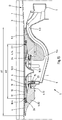
- the drain fitting 5 comprises a drain housing 9 having an inlet opening 6 and a connection 7 for a drain pipe 8. Furthermore, the drain fitting 5 comprises a cover 10.
- the cover 10 is detachably connected to the flange 4 and / or the drain housing 9 and covers in the assembled state State the inlet opening 6 of the drain housing 9 with the delimitation of an inlet gap 11.
- the flange 4 has a horizontal outer dimension or an outer diameter A1 which is significantly larger than a horizontal outer dimension (e.g. outer diameter A2) of the cover 10 that is aligned relative to the outer dimension of the flange (e.g. outer diameter A2).
- the outer diameter aluminum is at least 5%, preferably at least 15% larger than the horizontal outer dimension (e.g. outer diameter A2) of the covering hood 10, which is in the same direction relative to the outer dimension of the flange.
- the flange 4 has an inlet surface 4.2 which is lower relative to its connection surface 4.1 and which, in the assembled state of the drain fitting 5, surrounds the inlet opening 6 of the drain housing 9 and is spaced apart from the underside of the cover hood 10.
- the connection surface 4.1 of the flange is connected in one piece to the inlet surface 4.2 surrounding the inlet opening 6 of the drain housing via a conical inlet surface 4.3.
- the cover 10 has spacers 12 on its underside, with which it rests on the inlet surface 4.2.
- the cover 10 preferably has an enamelled decorative plate 10.1 on the top.
- the decorative plate 10.1 is fastened, for example glued, to a carrier 10.2 having the spacers 12.
- the carrier 10.2 with the spacers 12 protruding downward can be manufactured inexpensively from plastic.
- the spacers 12 are dimensioned such that the top of the decorative plate 10.1 of the cover 10 and the top of the edge region 3 of the shower tray surrounding the drain opening 2 run flush with one another, preferably flush with one another.
- the cover 10 or the decorative plate 10.1 is preferably curved slightly upwards.
- the drain opening 2 of the shower tray and the cover 10 are relatively large.
- the horizontal external dimension or the external diameter of the decorative plate 10.1 of the covering hood 10 is at least 130 mm, preferably at least 150 mm, particularly preferably 180 mm.
- the external dimension or the external diameter of the decorative plate 10.1 of the cover 10 can be at least 200 mm.
- the drain opening 2 and the cover 10 delimit a circumferential upper inlet gap 11.1, which has a gap width, for example, in the range of approximately 1.5 mm to 4 mm, preferably in the range of approximately 1.5 mm to 2.5 mm.
- the cover hood namely its decorative plate 10.1 defines a hood edge 10.4.
- the covering hood 10 is arranged in such a way that the perforated edge 2.1 of the drain opening 2 and the hood edge 10.4 are butted against each other, delimiting the inlet gap 11.1.
- the circumferential inlet gap 11.1 has an inlet cross-sectional area, for example in the range from approx. 1500 mm 2 to approx. 3500 mm 2 , preferably in the range from approx. 1500 mm 2 to approx. 3000 mm 2 , in particular in the range from approx. 1200 mm 2 can be up to approx. 2000 mm 2 .
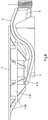
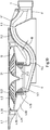
- the drain housing 9 has a pot-shaped housing section 9.1, to which a substantially S-shaped or wave-shaped drain channel 9.2 adjoins at the side.
- the drainage channel 9.2 is shaped in such a way that it has an overflow edge 9.3 which is significantly higher than a lower inlet edge 9.4 which is formed at the transition from the cup-shaped housing section 9.1 to the drainage channel 9.2.
- the vertical distance between the lower inlet edge 9.4 and the overflow edge 9.3 following in the direction of flow defines a water seal height and is approximately 50 mm, for example.
- the water present in the wave-shaped drainage channel 9.2 acts as a sealing water and serves as an odor trap.
- the drainage channel 9.2 has a flat channel cross-section between the lower inlet edge 9.4 and the overflow edge 9.3, the width B or horizontal inner dimension of which is a multiple of the channel height H measured relative to it orthogonally (cf. Figures 1 , la and 2).
- the width B of the drainage channel 9.2 essentially corresponds to that in Fig. 1 shown largest inside width (inside diameter) of the cup-shaped housing section 9.1.
- connection 7 which follows the overflow edge 9.3 of the drainage channel in the direction of flow, for a drainage pipe 8 is preferably designed as a circular cylindrical connection piece.
- a drain pipe 8 for example in the form of a pipe angle, is inserted into the connection 7.
- An external thread is formed on the outer circumference of the connection 7, onto which a union nut 14 comprising a sealing ring 13 is screwed for the frictional connection of the drain pipe 8.
- the drain housing 9 can preferably be detachably mounted on the flange (adapter flange) 4.
- the releasable connection is designed, for example, as a screw connection.
- vertically extending threaded sleeves 15 into which fastening screws are screwed are integrated in the wall of the cup-shaped housing section 9.1.
- the fastening screws are inserted into fastening holes that are evenly spaced from one another on a pitch circle that surrounds the passage opening 4.5 defined by the flange 4, through which water flowing from the shower tray base 1 flows into the drain housing 9.
- the fastening holes are formed in the flange 4 or in an additional fastening flange which can be inserted into the flange 4 connected or connectable to the shower tray.
- the diameter of these fastening holes is smaller than the diameter of the head of the fastening screws inserted therein.
- the spacers 12 of the cover hood comprise recesses 16 which serve to receive the positive-locking reception of the heads of the fastening screws protruding upwards in relation to the inlet surface 4.2 of the flange.
- the cup-shaped housing section 9.1 of the drain housing has on its upper side an annular connection surface on which a sealing ring 17 made of elastomer lies.
- the flange 4 has on its underside a rib structure 4.6 facing the sealing ring 17.
- the rib structure 4.6 can, for example, comprise a plurality of annular, radially spaced apart, coaxially arranged ribs which, after the flange 4 and drain housing 9 have been connected, press sealingly into the elastic sealing ring 17.
- a hair strainer 18 can be arranged below the removable cover hood 10.
- the hair sieve 18 is preferably inserted removably into the inlet opening 6 of the drain housing 9.
- the hair sieve 18 is preferably provided with a pin-shaped, centrally arranged handle 19 (cf. FIG. 1 a).
- FIG. 5 The illustrated embodiment differs from that in the Figures 1 to 4
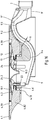
- the embodiment shown in that the flange 4 has a plurality of through holes 4.7 in the area of its connection surface 4.1 for receiving fastening means 20 connected to the underside of the shower tray base 1.
- the fastening means 20 are, for example, screw bolts connected to the underside of the shower tray D, onto which fastening nuts are screwed.
- the flange 4 can thus also be connected to the shower tray D in a non-positive manner.
- the through holes 4.7 of the flange 4 can also be used for anchoring adhesive arranged between the underside of the shower tray base 1 and the connection surface 4.1 of the flange 4.
- a further embodiment of the invention is shown.
- a shower tray D is shown, which is of particularly flat design, the bottom 1 of the shower tray D being designed with a slight gradient from the outer edges to the drain opening 2.
- the angle of inclination of the slope is, for example, in the range from 1 ° to 3 °.
- the drain opening 2 is, for example, circular.
- the edge area of the shower tray base surrounding the drain opening has a conical embossing that protrudes downward compared to the underside of the base
- the in FIG Figures 6 , 7th and 9 The shower tray D shown in the edge area 3 immediately surrounding the drain opening 2, the radial edge width of which is, for example, at least 80 mm, has no downwardly protruding embossing. Rather, the edge region 3 surrounding the drainage opening 2 is essentially flat.
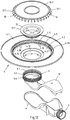
- a flange 4 is attached to the underside of the shower tray D in the area of the drain opening 2.
- the flange 4 is part of a drain fitting 5 and has a connection on the underside of the shower tray base 1 certain annular connection surface 4.1 (cf. Fig. 10 , 11 and 12th ).
- the flange 4 is in turn designed in such a way that it can be connected to the shower tray D in a liquid-tight manner without a connecting counterpart resting on the top of the shower tray base 1.
- the flange 4 is or is cohesively connected to the underside of the shower tray base 1.
- the cohesive, liquid-tight connection can be realized, for example, by means of adhesive applied in a ring to the connection surface 4.1 or by means of a double-sided adhesive ring.
- the flange 4 is preferably designed as a molded part and made of plastic or metal.
- Reinforcing ribs 4.81, 4.82 are formed on the underside of the flange 4, which include, for example, a central, annular reinforcing rib 4.81 and a plurality of radially extending reinforcing ribs 4.82.
- the drain fitting 5 has a drain housing 9 which has an inlet opening 6 and a connection 7 for a drain pipe.
- the drain fitting 5 also comprises a cover hood 10.
- the cover hood 10 is detachably connected to the flange 4 or the drain housing 9 and, in the assembled state, covers the inlet opening 6 of the drain housing 9 while delimiting an inlet gap 11.
- the flange 4 has a horizontal outer dimension or an outer diameter A1 which is significantly larger than the outer diameter A2 of the cover 10 or a horizontal outer dimension of the cover 10 that is in the same direction relative to the outer dimension of the flange 10.
- the horizontal outer dimension or the outer diameter is aluminum at least 5%, preferably at least 15% larger than the horizontal outer dimension (e.g. outer diameter A2) of the cover 10 that is aligned in the same direction relative to the outer dimension of the flange.
- the flange 4 defines an inlet surface 4.2 which is lower relative to the connection surface 4.1 and which, when the drain fitting 5 is installed, surrounds the inlet opening 6 of the drain housing 9 and is at a distance from the underside of the cover hood 10.
- the cover 10 is provided on its underside with spacers 12 with which it rests on the inlet surface 4.2.
- a circumferential annular groove 4.30 for receiving an annular seal 26 is formed in the connection surface 4.1 of the flange 4.
- the annular groove 4.30 surrounds the inlet surface 4.2 and is preferably arranged at a relatively small distance from the inlet surface 4.2, for example at a distance in the range of approximately 2 mm to 15 mm, in the connection surface 4.1 of the flange 4.
- the inlet surface 4.2 which is lower relative to the connection surface 4.1, is inclined, preferably conical, towards the inlet opening 6 of the drain housing.
- the inlet surface 4.2 is limited to the outside by a circumferential shoulder or a circumferential inner wall 4.9.
- the run-off of water into the drain housing 9 is promoted by the inlet surface 4.2, which is designed with a gradient.
- the embodiment shown has the cover 10 a decorative plate 10.1.
- the preferably enamelled decorative plate 10.1 is in turn fastened to a carrier 10.2 which has the spacers 12 and which can be manufactured inexpensively from plastic.
- the cover hood 10 can be centered on the circumferential wall 4.9 of the flange 4 relative to the drain opening 2 of the shower tray D.
- the spacers 12 are, for example, rib-shaped or web-shaped and protrude radially beyond the outer edge of the cover hood 10. At least some of the spacers 12 abut with their outer end faces 12.1 against the circumferential one Paragraph or the surrounding wall 4.9.
- the spacers 12 are designed, for example, in such a way that their ends protruding radially beyond the outer edge of the carrier 10.2 of the decorative plate 10.1 of the covering hood 10 are inclined towards the outer end face 12.1.
- the circumferential shoulder or the circumferential inner wall 4.9 has a multiplicity of projections 4.10, the spacers 12 engaging in recesses 4.11 delimited by the projections 4.10. This positive connection prevents or locks the cover 10 from rotating about a vertical axis relative to the flange 4.
- the cover 10 or the support 10.2 of the cover has a tapering liquid guiding element 10.3 on the underside, which is designed, for example, in the form of a hyperbolic cone or hyperbolic truncated cone, the tip or taper of the liquid guiding element 10.3 protruding into the inlet opening 6 of the drain housing 9.
- the flange 4 has a cylindrical receptacle 4.12 into which a cylindrical connection piece 9.5 formed on the drain housing 9 is or will be inserted.
- the receptacle 4.12 is defined by an inner cylindrical annular web 4.13 of the flange 4.
- the connection piece 9.5 has on its outside parallel to one another circumferential ribs or annular grooves 9.6, into which, for example, a sealing ring (O-ring) can be inserted.
- a circumferential, radially inwardly protruding projection 4.14 is formed, which serves as an axial stop for the connection piece 9.5 (cf. Fig. 9 and 12th ).
- a screw flange 21 is provided for connecting the flange 4 and the drain housing 9, by means of which the inlet surface 4.2 of the flange 4 is or will be connected to the drain housing 9.
- the connection piece 9.5 of the drain housing 9 has an internal thread 9.7 into which the screw flange 21 is screwed.
- An annular shoulder 4.21 for the form-fitting reception of the flange section 21.1 of the screw flange 21 is formed on the inlet surface 4.2.
- the screw flange 21 is provided with grip elements 21.2.
- the grip elements 21.2 enable the screw flange 21 to be screwed into the internal thread 9.7 formed on the inlet opening 6 of the drain housing 9 without tools.
- the grip elements 21.2 are designed, for example, in the form of ribs and are arranged on the inside of the screw flange 21.
- the ribs 21.2 preferably protrude radially from the inside of the screw flange 21 and have end edges which extend arcuately downward from the upper end of the respective rib 21.2 in the direction of the central axis of the screw flange 21.
- the dimensions of the drain opening 2, the cover hood 10, in particular the decorative plate 10.1, the inlet gap 11.1 and the gap width correspond to the above with reference to the in the Figures 1 to 5 Embodiments shown specified dimensions, so that to avoid repetition, reference is made to the preceding description.
- the drain housing 9 is essentially composed of a lower housing part 9 'and an upper housing part 9 ′′, which are or will be glued or welded to one another (cf. Fig. 12 ).
- the fastening screws 23 are combined with a fastening flange 24 which has fastening holes for inserting the fastening screws 23.
- the fastening holes are provided, for example, in radially inwardly projecting ears 24.2 of the fastening flange 24, which is preferably made of stainless steel.
- the fastening screws 23 are countersunk head screws. Accordingly, the fastening holes of the fastening flange 24 are essentially conical.
- the pot-shaped housing section 9.1 of the drain housing again has an annular connection surface 9.5 'on its upper side, on which a sealing ring 17 made of elastomer lies.
- the flange 4 On its underside, has a contact surface 4.6 ′ facing the sealing ring 17.
- the contact surface 4.6 ' can be designed to be essentially smooth or in the form of a rib structure, for example a rib structure 4.6 according to FIG.
- annular shoulder 4.21 is designed to receive a flange section 24.1 of the fastening flange 24 in a form-fitting manner.
- the cover 10 is in turn provided on its underside with spacers 12 with which it rests on the inlet surface 4.2 of the flange.
- the spacers 12 are rib-shaped or web-shaped and protrude beyond the outer edge of the cover hood 10. At least some of the spacers 12 abut with their outer end faces 12.1 on the circumferential shoulder or the circumferential wall 4.9 of the flange.
- the spacers 12 are designed, for example, in such a way that their ends protruding radially beyond the outer edge of the carrier 10.2 of the decorative panel 10.1 of the cover hood have a stepped reduced height towards the outer end face 12.1.
- the spacers 12 according to Fig. 18 wider and define a comparatively coarse star-shaped spoke structure with larger recesses between the spokes or spacers 12.
- FIGS. 15 , 16 and 18th show that the circumferential inner wall 4.9 of the flange has a plurality of projections 4.10, and that the spacers 12 engage in recesses 4.11 delimited by the projections 4.10. This form fit prevents or locks the cover 10 from rotating about a vertical axis relative to the flange 4.
- the dimensions of the drain opening 2, the cover 10, the decorative plate 10.1, the inlet gap 11.1 and the gap width correspond to the in the Figures 13 to 18
- the exemplary embodiment shown also has the dimensions already specified above with reference to the other exemplary embodiments, so that in order to avoid repetition, in particular, refer to the description of the Figures 1 to 5 is referred.
- the drain opening 2 of the shower tray D and the cover hood 10 can also be rectangular, in particular square, or oval.
Landscapes
- Engineering & Computer Science (AREA)
- Health & Medical Sciences (AREA)
- Public Health (AREA)
- Life Sciences & Earth Sciences (AREA)
- Hydrology & Water Resources (AREA)
- Water Supply & Treatment (AREA)
- Environmental & Geological Engineering (AREA)
- Epidemiology (AREA)
- General Health & Medical Sciences (AREA)
- Sink And Installation For Waste Water (AREA)
Applications Claiming Priority (1)
| Application Number | Priority Date | Filing Date | Title |
|---|---|---|---|
| DE102019135423.4A DE102019135423A1 (de) | 2019-12-20 | 2019-12-20 | Sanitäre Wanne, insbesondere Duschtasse |
Publications (2)
| Publication Number | Publication Date |
|---|---|
| EP3839158A1 true EP3839158A1 (fr) | 2021-06-23 |
| EP3839158B1 EP3839158B1 (fr) | 2023-08-16 |
Family
ID=73793051
Family Applications (1)
| Application Number | Title | Priority Date | Filing Date |
|---|---|---|---|
| EP20213057.1A Active EP3839158B1 (fr) | 2019-12-20 | 2020-12-10 | Receveur de douche |
Country Status (3)
| Country | Link |
|---|---|
| EP (1) | EP3839158B1 (fr) |
| DE (1) | DE102019135423A1 (fr) |
| RU (1) | RU2757451C1 (fr) |
Cited By (2)
| Publication number | Priority date | Publication date | Assignee | Title |
|---|---|---|---|---|
| USD982866S1 (en) * | 2022-10-14 | 2023-04-04 | Zonghua Hu | Bowl sink grid |
| EP4575109A1 (fr) * | 2023-12-20 | 2025-06-25 | Viega Technology GmbH & Co. KG | Bouche d'écoulement avec tamis pour retenir les saletés notamment pour un bac de douche |
Citations (6)
| Publication number | Priority date | Publication date | Assignee | Title |
|---|---|---|---|---|
| GB1300065A (en) * | 1969-11-21 | 1972-12-20 | Easiclene Domestic Equipment L | Improvements relating to sinks |
| DE102006030481A1 (de) | 2006-07-01 | 2008-01-10 | Bette Gmbh & Co. Kg | Duschwanne und Verfahren zu ihrer Herstellung |
| WO2010083568A2 (fr) * | 2009-01-22 | 2010-07-29 | William Francis Swanston | Grille de déversoir |
| DE102012215764A1 (de) * | 2012-09-05 | 2014-03-06 | Blanco Gmbh + Co Kg | Siebelement für einen Ablauf eines Beckens |
| DE102012215761A1 (de) * | 2012-09-05 | 2014-03-06 | Blanco Gmbh + Co Kg | Ablaufgarnitur und Verfahren zum Anordnen einer Ablaufgarnitur an einem Ablaufflansch eines Beckens |
| DE202018104241U1 (de) * | 2018-07-24 | 2019-10-25 | Viega Technology Gmbh & Co. Kg | Ablaufhaube für eine Ablaufgarnitur für Bade- und/oder Duschwannen |
Family Cites Families (6)
| Publication number | Priority date | Publication date | Assignee | Title |
|---|---|---|---|---|
| FR1035381A (fr) * | 1951-04-13 | 1953-08-24 | Receveur de douche | |
| DE202006014440U1 (de) * | 2005-09-19 | 2007-02-15 | Illbruck Sanitärtechnik GmbH | Duschbodenelement aus einem Hartschaumstoff |
| US7739757B2 (en) * | 2006-12-20 | 2010-06-22 | Kohler Co. | Shower base with flow enhancing covered drain |
| US9107545B1 (en) * | 2010-01-14 | 2015-08-18 | Avery S. Herring | One piece shower pan and method of making same |
| DE202014101176U1 (de) * | 2014-03-14 | 2015-06-17 | Viega Gmbh & Co. Kg | Ablaufgarnitur für eine Bodenablaufrinne und Bodenablaufrinne mit einer solchen Ablaufgarnitur |
| DE102015102247B4 (de) * | 2015-02-17 | 2018-09-20 | Wedi Gmbh | Duschbodenplattenmodul |
-
2019
- 2019-12-20 DE DE102019135423.4A patent/DE102019135423A1/de not_active Ceased
-
2020
- 2020-12-10 EP EP20213057.1A patent/EP3839158B1/fr active Active
- 2020-12-17 RU RU2020141814A patent/RU2757451C1/ru active
Patent Citations (6)
| Publication number | Priority date | Publication date | Assignee | Title |
|---|---|---|---|---|
| GB1300065A (en) * | 1969-11-21 | 1972-12-20 | Easiclene Domestic Equipment L | Improvements relating to sinks |
| DE102006030481A1 (de) | 2006-07-01 | 2008-01-10 | Bette Gmbh & Co. Kg | Duschwanne und Verfahren zu ihrer Herstellung |
| WO2010083568A2 (fr) * | 2009-01-22 | 2010-07-29 | William Francis Swanston | Grille de déversoir |
| DE102012215764A1 (de) * | 2012-09-05 | 2014-03-06 | Blanco Gmbh + Co Kg | Siebelement für einen Ablauf eines Beckens |
| DE102012215761A1 (de) * | 2012-09-05 | 2014-03-06 | Blanco Gmbh + Co Kg | Ablaufgarnitur und Verfahren zum Anordnen einer Ablaufgarnitur an einem Ablaufflansch eines Beckens |
| DE202018104241U1 (de) * | 2018-07-24 | 2019-10-25 | Viega Technology Gmbh & Co. Kg | Ablaufhaube für eine Ablaufgarnitur für Bade- und/oder Duschwannen |
Cited By (2)
| Publication number | Priority date | Publication date | Assignee | Title |
|---|---|---|---|---|
| USD982866S1 (en) * | 2022-10-14 | 2023-04-04 | Zonghua Hu | Bowl sink grid |
| EP4575109A1 (fr) * | 2023-12-20 | 2025-06-25 | Viega Technology GmbH & Co. KG | Bouche d'écoulement avec tamis pour retenir les saletés notamment pour un bac de douche |
Also Published As
| Publication number | Publication date |
|---|---|
| DE102019135423A1 (de) | 2021-06-24 |
| RU2757451C1 (ru) | 2021-10-15 |
| EP3839158B1 (fr) | 2023-08-16 |
Similar Documents
| Publication | Publication Date | Title |
|---|---|---|
| EP3839157B1 (fr) | Robinetterie d'évacuation pour une baignoire sanitaire ou un receveur de douche | |
| EP2423394B1 (fr) | Rigole d'écoulement pour douches à même le sol | |
| EP2108751B1 (fr) | Armature d'écoulement pour baignoire ou bac de douche dotés d'une alimentation au sol | |
| DE29707890U1 (de) | Vorrichtung zur Befestigung eines Handlaufelements an einem Pfosten, insbesondere zur Herstellung eines Treppengeländers, und Bausatz dafür | |
| DE102016103064A1 (de) | Sanitärwannenanordnung | |
| EP3839158B1 (fr) | Receveur de douche | |
| CH704479A2 (de) | Sanitärwanne. | |
| EP2083125B1 (fr) | Armature d'écoulement, notamment pour douches ou baignoires | |
| EP3599315B1 (fr) | Capot d'écoulement pour une garniture d'écoulement pour receveurs de bain et / ou de douche | |
| EP1245741A2 (fr) | Robinetterie sanitaire | |
| EP2703573B1 (fr) | Bouche d'égout et bac de douche ou baignoire avec une telle bouche d'égout | |
| EP1783285B1 (fr) | Dispositif de drainage ajustable pour blocs sanitaires | |
| EP4030006B1 (fr) | Armature d'évacuation, en particulier pour receveurs de douche, pourvue de tube plongeur variable pouvant être coupé à longueur | |
| DE102023135951A1 (de) | Ablaufarmatur mit Schmutzfangsieb, insbesondere für eine Duschwanne | |
| DE29509070U1 (de) | Selbsttränkebecken für Tiere | |
| DE29816875U1 (de) | Vorrichtung zur Befestigung von Zusatzteilen | |
| DE102019132270B3 (de) | Sanitärwanne | |
| EP2372029B1 (fr) | Armature d'écoulement pour baignoire ou bac à douche dotés d'une alimentation au sol | |
| EP3406810B1 (fr) | Évier doté d'une d'ouverture d'écoulement et d'un module d'écoulement | |
| EP1967664A2 (fr) | Lavabo en deux parties | |
| DE202024101887U1 (de) | Waschbecken und Waschtischanordnung | |
| EP4477811A1 (fr) | Dispositif de recouvrement de vidange pour une ouverture de vidange et dispositif de drainage d'eau doté d'un dispositif de recouvrement de vidange | |
| EP2735661A1 (fr) | Cuve sanitaire | |
| DE102007040234A1 (de) | Überlaufkörper zum Anordnen an einer Überlauföffnung | |
| EP1856336A1 (fr) | Robinet sanitaire dote d'un moderateur destine a la reduction des turbulences dans la zone de l'unite d'ecoulement d'eau ouverte |
Legal Events
| Date | Code | Title | Description |
|---|---|---|---|
| PUAI | Public reference made under article 153(3) epc to a published international application that has entered the european phase |
Free format text: ORIGINAL CODE: 0009012 |
|
| STAA | Information on the status of an ep patent application or granted ep patent |
Free format text: STATUS: THE APPLICATION HAS BEEN PUBLISHED |
|
| AK | Designated contracting states |
Kind code of ref document: A1 Designated state(s): AL AT BE BG CH CY CZ DE DK EE ES FI FR GB GR HR HU IE IS IT LI LT LU LV MC MK MT NL NO PL PT RO RS SE SI SK SM TR |
|
| STAA | Information on the status of an ep patent application or granted ep patent |
Free format text: STATUS: REQUEST FOR EXAMINATION WAS MADE |
|
| 17P | Request for examination filed |
Effective date: 20210701 |
|
| RBV | Designated contracting states (corrected) |
Designated state(s): AL AT BE BG CH CY CZ DE DK EE ES FI FR GB GR HR HU IE IS IT LI LT LU LV MC MK MT NL NO PL PT RO RS SE SI SK SM TR |
|
| GRAP | Despatch of communication of intention to grant a patent |
Free format text: ORIGINAL CODE: EPIDOSNIGR1 |
|
| STAA | Information on the status of an ep patent application or granted ep patent |
Free format text: STATUS: GRANT OF PATENT IS INTENDED |
|
| INTG | Intention to grant announced |
Effective date: 20230307 |
|
| GRAS | Grant fee paid |
Free format text: ORIGINAL CODE: EPIDOSNIGR3 |
|
| GRAA | (expected) grant |
Free format text: ORIGINAL CODE: 0009210 |
|
| STAA | Information on the status of an ep patent application or granted ep patent |
Free format text: STATUS: THE PATENT HAS BEEN GRANTED |
|
| AK | Designated contracting states |
Kind code of ref document: B1 Designated state(s): AL AT BE BG CH CY CZ DE DK EE ES FI FR GB GR HR HU IE IS IT LI LT LU LV MC MK MT NL NO PL PT RO RS SE SI SK SM TR |
|
| REG | Reference to a national code |
Ref country code: CH Ref legal event code: EP Ref country code: DE Ref legal event code: R096 Ref document number: 502020004733 Country of ref document: DE |
|
| P01 | Opt-out of the competence of the unified patent court (upc) registered |
Effective date: 20230731 |
|
| REG | Reference to a national code |
Ref country code: IE Ref legal event code: FG4D Free format text: LANGUAGE OF EP DOCUMENT: GERMAN |
|
| REG | Reference to a national code |
Ref country code: LT Ref legal event code: MG9D |
|
| REG | Reference to a national code |
Ref country code: NL Ref legal event code: MP Effective date: 20230816 |
|
| PG25 | Lapsed in a contracting state [announced via postgrant information from national office to epo] |
Ref country code: IS Free format text: LAPSE BECAUSE OF FAILURE TO SUBMIT A TRANSLATION OF THE DESCRIPTION OR TO PAY THE FEE WITHIN THE PRESCRIBED TIME-LIMIT Effective date: 20231216 |
|
| PG25 | Lapsed in a contracting state [announced via postgrant information from national office to epo] |
Ref country code: SE Free format text: LAPSE BECAUSE OF FAILURE TO SUBMIT A TRANSLATION OF THE DESCRIPTION OR TO PAY THE FEE WITHIN THE PRESCRIBED TIME-LIMIT Effective date: 20230816 Ref country code: RS Free format text: LAPSE BECAUSE OF FAILURE TO SUBMIT A TRANSLATION OF THE DESCRIPTION OR TO PAY THE FEE WITHIN THE PRESCRIBED TIME-LIMIT Effective date: 20230816 Ref country code: PT Free format text: LAPSE BECAUSE OF FAILURE TO SUBMIT A TRANSLATION OF THE DESCRIPTION OR TO PAY THE FEE WITHIN THE PRESCRIBED TIME-LIMIT Effective date: 20231218 Ref country code: NO Free format text: LAPSE BECAUSE OF FAILURE TO SUBMIT A TRANSLATION OF THE DESCRIPTION OR TO PAY THE FEE WITHIN THE PRESCRIBED TIME-LIMIT Effective date: 20231116 Ref country code: NL Free format text: LAPSE BECAUSE OF FAILURE TO SUBMIT A TRANSLATION OF THE DESCRIPTION OR TO PAY THE FEE WITHIN THE PRESCRIBED TIME-LIMIT Effective date: 20230816 Ref country code: LV Free format text: LAPSE BECAUSE OF FAILURE TO SUBMIT A TRANSLATION OF THE DESCRIPTION OR TO PAY THE FEE WITHIN THE PRESCRIBED TIME-LIMIT Effective date: 20230816 Ref country code: LT Free format text: LAPSE BECAUSE OF FAILURE TO SUBMIT A TRANSLATION OF THE DESCRIPTION OR TO PAY THE FEE WITHIN THE PRESCRIBED TIME-LIMIT Effective date: 20230816 Ref country code: IS Free format text: LAPSE BECAUSE OF FAILURE TO SUBMIT A TRANSLATION OF THE DESCRIPTION OR TO PAY THE FEE WITHIN THE PRESCRIBED TIME-LIMIT Effective date: 20231216 Ref country code: HR Free format text: LAPSE BECAUSE OF FAILURE TO SUBMIT A TRANSLATION OF THE DESCRIPTION OR TO PAY THE FEE WITHIN THE PRESCRIBED TIME-LIMIT Effective date: 20230816 Ref country code: FI Free format text: LAPSE BECAUSE OF FAILURE TO SUBMIT A TRANSLATION OF THE DESCRIPTION OR TO PAY THE FEE WITHIN THE PRESCRIBED TIME-LIMIT Effective date: 20230816 |
|
| PG25 | Lapsed in a contracting state [announced via postgrant information from national office to epo] |
Ref country code: PL Free format text: LAPSE BECAUSE OF FAILURE TO SUBMIT A TRANSLATION OF THE DESCRIPTION OR TO PAY THE FEE WITHIN THE PRESCRIBED TIME-LIMIT Effective date: 20230816 |
|
| PG25 | Lapsed in a contracting state [announced via postgrant information from national office to epo] |
Ref country code: ES Free format text: LAPSE BECAUSE OF FAILURE TO SUBMIT A TRANSLATION OF THE DESCRIPTION OR TO PAY THE FEE WITHIN THE PRESCRIBED TIME-LIMIT Effective date: 20230816 |
|
| PG25 | Lapsed in a contracting state [announced via postgrant information from national office to epo] |
Ref country code: SM Free format text: LAPSE BECAUSE OF FAILURE TO SUBMIT A TRANSLATION OF THE DESCRIPTION OR TO PAY THE FEE WITHIN THE PRESCRIBED TIME-LIMIT Effective date: 20230816 Ref country code: RO Free format text: LAPSE BECAUSE OF FAILURE TO SUBMIT A TRANSLATION OF THE DESCRIPTION OR TO PAY THE FEE WITHIN THE PRESCRIBED TIME-LIMIT Effective date: 20230816 Ref country code: ES Free format text: LAPSE BECAUSE OF FAILURE TO SUBMIT A TRANSLATION OF THE DESCRIPTION OR TO PAY THE FEE WITHIN THE PRESCRIBED TIME-LIMIT Effective date: 20230816 Ref country code: EE Free format text: LAPSE BECAUSE OF FAILURE TO SUBMIT A TRANSLATION OF THE DESCRIPTION OR TO PAY THE FEE WITHIN THE PRESCRIBED TIME-LIMIT Effective date: 20230816 Ref country code: DK Free format text: LAPSE BECAUSE OF FAILURE TO SUBMIT A TRANSLATION OF THE DESCRIPTION OR TO PAY THE FEE WITHIN THE PRESCRIBED TIME-LIMIT Effective date: 20230816 Ref country code: CZ Free format text: LAPSE BECAUSE OF FAILURE TO SUBMIT A TRANSLATION OF THE DESCRIPTION OR TO PAY THE FEE WITHIN THE PRESCRIBED TIME-LIMIT Effective date: 20230816 Ref country code: SK Free format text: LAPSE BECAUSE OF FAILURE TO SUBMIT A TRANSLATION OF THE DESCRIPTION OR TO PAY THE FEE WITHIN THE PRESCRIBED TIME-LIMIT Effective date: 20230816 |
|
| REG | Reference to a national code |
Ref country code: DE Ref legal event code: R097 Ref document number: 502020004733 Country of ref document: DE |
|
| PLBE | No opposition filed within time limit |
Free format text: ORIGINAL CODE: 0009261 |
|
| STAA | Information on the status of an ep patent application or granted ep patent |
Free format text: STATUS: NO OPPOSITION FILED WITHIN TIME LIMIT |
|
| 26N | No opposition filed |
Effective date: 20240517 |
|
| PG25 | Lapsed in a contracting state [announced via postgrant information from national office to epo] |
Ref country code: IT Free format text: LAPSE BECAUSE OF NON-PAYMENT OF DUE FEES Effective date: 20231210 Ref country code: SI Free format text: LAPSE BECAUSE OF FAILURE TO SUBMIT A TRANSLATION OF THE DESCRIPTION OR TO PAY THE FEE WITHIN THE PRESCRIBED TIME-LIMIT Effective date: 20230816 |
|
| PG25 | Lapsed in a contracting state [announced via postgrant information from national office to epo] |
Ref country code: LU Free format text: LAPSE BECAUSE OF NON-PAYMENT OF DUE FEES Effective date: 20231210 |
|
| PG25 | Lapsed in a contracting state [announced via postgrant information from national office to epo] |
Ref country code: MC Free format text: LAPSE BECAUSE OF FAILURE TO SUBMIT A TRANSLATION OF THE DESCRIPTION OR TO PAY THE FEE WITHIN THE PRESCRIBED TIME-LIMIT Effective date: 20230816 |
|
| REG | Reference to a national code |
Ref country code: BE Ref legal event code: MM Effective date: 20231231 |
|
| PG25 | Lapsed in a contracting state [announced via postgrant information from national office to epo] |
Ref country code: MC Free format text: LAPSE BECAUSE OF FAILURE TO SUBMIT A TRANSLATION OF THE DESCRIPTION OR TO PAY THE FEE WITHIN THE PRESCRIBED TIME-LIMIT Effective date: 20230816 Ref country code: LU Free format text: LAPSE BECAUSE OF NON-PAYMENT OF DUE FEES Effective date: 20231210 |
|
| REG | Reference to a national code |
Ref country code: IE Ref legal event code: MM4A |
|
| PG25 | Lapsed in a contracting state [announced via postgrant information from national office to epo] |
Ref country code: IE Free format text: LAPSE BECAUSE OF NON-PAYMENT OF DUE FEES Effective date: 20231210 |
|
| PG25 | Lapsed in a contracting state [announced via postgrant information from national office to epo] |
Ref country code: BE Free format text: LAPSE BECAUSE OF NON-PAYMENT OF DUE FEES Effective date: 20231231 |
|
| PG25 | Lapsed in a contracting state [announced via postgrant information from national office to epo] |
Ref country code: IE Free format text: LAPSE BECAUSE OF NON-PAYMENT OF DUE FEES Effective date: 20231210 Ref country code: BE Free format text: LAPSE BECAUSE OF NON-PAYMENT OF DUE FEES Effective date: 20231231 |
|
| PG25 | Lapsed in a contracting state [announced via postgrant information from national office to epo] |
Ref country code: BG Free format text: LAPSE BECAUSE OF FAILURE TO SUBMIT A TRANSLATION OF THE DESCRIPTION OR TO PAY THE FEE WITHIN THE PRESCRIBED TIME-LIMIT Effective date: 20230816 |
|
| PG25 | Lapsed in a contracting state [announced via postgrant information from national office to epo] |
Ref country code: BG Free format text: LAPSE BECAUSE OF FAILURE TO SUBMIT A TRANSLATION OF THE DESCRIPTION OR TO PAY THE FEE WITHIN THE PRESCRIBED TIME-LIMIT Effective date: 20230816 |
|
| PG25 | Lapsed in a contracting state [announced via postgrant information from national office to epo] |
Ref country code: IT Free format text: LAPSE BECAUSE OF NON-PAYMENT OF DUE FEES Effective date: 20231210 |
|
| PGRI | Patent reinstated in contracting state [announced from national office to epo] |
Ref country code: IT Effective date: 20240102 |
|
| PG25 | Lapsed in a contracting state [announced via postgrant information from national office to epo] |
Ref country code: IT Free format text: LAPSE BECAUSE OF NON-PAYMENT OF DUE FEES Effective date: 20231210 |
|
| PGRI | Patent reinstated in contracting state [announced from national office to epo] |
Ref country code: IT Effective date: 20240102 |
|
| PGFP | Annual fee paid to national office [announced via postgrant information from national office to epo] |
Ref country code: CH Payment date: 20250101 Year of fee payment: 5 |
|
| PG25 | Lapsed in a contracting state [announced via postgrant information from national office to epo] |
Ref country code: CY Free format text: LAPSE BECAUSE OF FAILURE TO SUBMIT A TRANSLATION OF THE DESCRIPTION OR TO PAY THE FEE WITHIN THE PRESCRIBED TIME-LIMIT; INVALID AB INITIO Effective date: 20201210 |
|
| PG25 | Lapsed in a contracting state [announced via postgrant information from national office to epo] |
Ref country code: HU Free format text: LAPSE BECAUSE OF FAILURE TO SUBMIT A TRANSLATION OF THE DESCRIPTION OR TO PAY THE FEE WITHIN THE PRESCRIBED TIME-LIMIT; INVALID AB INITIO Effective date: 20201210 |
|
| PG25 | Lapsed in a contracting state [announced via postgrant information from national office to epo] |
Ref country code: GR Free format text: LAPSE BECAUSE OF FAILURE TO SUBMIT A TRANSLATION OF THE DESCRIPTION OR TO PAY THE FEE WITHIN THE PRESCRIBED TIME-LIMIT; INVALID AB INITIO Effective date: 20201210 |
|
| PG25 | Lapsed in a contracting state [announced via postgrant information from national office to epo] |
Ref country code: TR Free format text: LAPSE BECAUSE OF FAILURE TO SUBMIT A TRANSLATION OF THE DESCRIPTION OR TO PAY THE FEE WITHIN THE PRESCRIBED TIME-LIMIT Effective date: 20230816 |
|
| REG | Reference to a national code |
Ref country code: CH Ref legal event code: U11 Free format text: ST27 STATUS EVENT CODE: U-0-0-U10-U11 (AS PROVIDED BY THE NATIONAL OFFICE) Effective date: 20260101 |
|
| PGFP | Annual fee paid to national office [announced via postgrant information from national office to epo] |
Ref country code: DE Payment date: 20251217 Year of fee payment: 6 |
|
| PGFP | Annual fee paid to national office [announced via postgrant information from national office to epo] |
Ref country code: GB Payment date: 20251218 Year of fee payment: 6 |
|
| PGFP | Annual fee paid to national office [announced via postgrant information from national office to epo] |
Ref country code: AT Payment date: 20251219 Year of fee payment: 6 |
|
| PGFP | Annual fee paid to national office [announced via postgrant information from national office to epo] |
Ref country code: IT Payment date: 20251222 Year of fee payment: 6 |
|
| PGFP | Annual fee paid to national office [announced via postgrant information from national office to epo] |
Ref country code: FR Payment date: 20251217 Year of fee payment: 6 |