EP3839228B1 - System und verfahren zum zünden und betreiben eines gasturbinenmotors mit alternativen brennstoffen - Google Patents
System und verfahren zum zünden und betreiben eines gasturbinenmotors mit alternativen brennstoffen Download PDFInfo
- Publication number
- EP3839228B1 EP3839228B1 EP20211967.3A EP20211967A EP3839228B1 EP 3839228 B1 EP3839228 B1 EP 3839228B1 EP 20211967 A EP20211967 A EP 20211967A EP 3839228 B1 EP3839228 B1 EP 3839228B1
- Authority
- EP
- European Patent Office
- Prior art keywords
- ethanol
- supply system
- gas turbine
- liquid
- turbine engine
- Prior art date
- Legal status (The legal status is an assumption and is not a legal conclusion. Google has not performed a legal analysis and makes no representation as to the accuracy of the status listed.)
- Active
Links
Images



Classifications
-
- F—MECHANICAL ENGINEERING; LIGHTING; HEATING; WEAPONS; BLASTING
- F02—COMBUSTION ENGINES; HOT-GAS OR COMBUSTION-PRODUCT ENGINE PLANTS
- F02C—GAS-TURBINE PLANTS; AIR INTAKES FOR JET-PROPULSION PLANTS; CONTROLLING FUEL SUPPLY IN AIR-BREATHING JET-PROPULSION PLANTS
- F02C3/00—Gas-turbine plants characterised by the use of combustion products as the working fluid
- F02C3/20—Gas-turbine plants characterised by the use of combustion products as the working fluid using a special fuel, oxidant, or dilution fluid to generate the combustion products
- F02C3/24—Gas-turbine plants characterised by the use of combustion products as the working fluid using a special fuel, oxidant, or dilution fluid to generate the combustion products the fuel or oxidant being liquid at standard temperature and pressure
-
- F—MECHANICAL ENGINEERING; LIGHTING; HEATING; WEAPONS; BLASTING
- F02—COMBUSTION ENGINES; HOT-GAS OR COMBUSTION-PRODUCT ENGINE PLANTS
- F02C—GAS-TURBINE PLANTS; AIR INTAKES FOR JET-PROPULSION PLANTS; CONTROLLING FUEL SUPPLY IN AIR-BREATHING JET-PROPULSION PLANTS
- F02C3/00—Gas-turbine plants characterised by the use of combustion products as the working fluid
- F02C3/20—Gas-turbine plants characterised by the use of combustion products as the working fluid using a special fuel, oxidant, or dilution fluid to generate the combustion products
-
- F—MECHANICAL ENGINEERING; LIGHTING; HEATING; WEAPONS; BLASTING
- F02—COMBUSTION ENGINES; HOT-GAS OR COMBUSTION-PRODUCT ENGINE PLANTS
- F02C—GAS-TURBINE PLANTS; AIR INTAKES FOR JET-PROPULSION PLANTS; CONTROLLING FUEL SUPPLY IN AIR-BREATHING JET-PROPULSION PLANTS
- F02C3/00—Gas-turbine plants characterised by the use of combustion products as the working fluid
- F02C3/14—Gas-turbine plants characterised by the use of combustion products as the working fluid characterised by the arrangement of the combustion chamber in the plant
-
- F—MECHANICAL ENGINEERING; LIGHTING; HEATING; WEAPONS; BLASTING
- F02—COMBUSTION ENGINES; HOT-GAS OR COMBUSTION-PRODUCT ENGINE PLANTS
- F02C—GAS-TURBINE PLANTS; AIR INTAKES FOR JET-PROPULSION PLANTS; CONTROLLING FUEL SUPPLY IN AIR-BREATHING JET-PROPULSION PLANTS
- F02C3/00—Gas-turbine plants characterised by the use of combustion products as the working fluid
- F02C3/20—Gas-turbine plants characterised by the use of combustion products as the working fluid using a special fuel, oxidant, or dilution fluid to generate the combustion products
- F02C3/30—Adding water, steam or other fluids for influencing combustion, e.g. to obtain cleaner exhaust gases
-
- F—MECHANICAL ENGINEERING; LIGHTING; HEATING; WEAPONS; BLASTING
- F02—COMBUSTION ENGINES; HOT-GAS OR COMBUSTION-PRODUCT ENGINE PLANTS
- F02C—GAS-TURBINE PLANTS; AIR INTAKES FOR JET-PROPULSION PLANTS; CONTROLLING FUEL SUPPLY IN AIR-BREATHING JET-PROPULSION PLANTS
- F02C7/00—Features, components parts, details or accessories, not provided for in, or of interest apart form groups F02C1/00 - F02C6/00; Air intakes for jet-propulsion plants
- F02C7/22—Fuel supply systems
-
- F—MECHANICAL ENGINEERING; LIGHTING; HEATING; WEAPONS; BLASTING
- F02—COMBUSTION ENGINES; HOT-GAS OR COMBUSTION-PRODUCT ENGINE PLANTS
- F02C—GAS-TURBINE PLANTS; AIR INTAKES FOR JET-PROPULSION PLANTS; CONTROLLING FUEL SUPPLY IN AIR-BREATHING JET-PROPULSION PLANTS
- F02C7/00—Features, components parts, details or accessories, not provided for in, or of interest apart form groups F02C1/00 - F02C6/00; Air intakes for jet-propulsion plants
- F02C7/22—Fuel supply systems
- F02C7/224—Heating fuel before feeding to the burner
-
- F—MECHANICAL ENGINEERING; LIGHTING; HEATING; WEAPONS; BLASTING
- F02—COMBUSTION ENGINES; HOT-GAS OR COMBUSTION-PRODUCT ENGINE PLANTS
- F02C—GAS-TURBINE PLANTS; AIR INTAKES FOR JET-PROPULSION PLANTS; CONTROLLING FUEL SUPPLY IN AIR-BREATHING JET-PROPULSION PLANTS
- F02C7/00—Features, components parts, details or accessories, not provided for in, or of interest apart form groups F02C1/00 - F02C6/00; Air intakes for jet-propulsion plants
- F02C7/26—Starting; Ignition
-
- F—MECHANICAL ENGINEERING; LIGHTING; HEATING; WEAPONS; BLASTING
- F02—COMBUSTION ENGINES; HOT-GAS OR COMBUSTION-PRODUCT ENGINE PLANTS
- F02C—GAS-TURBINE PLANTS; AIR INTAKES FOR JET-PROPULSION PLANTS; CONTROLLING FUEL SUPPLY IN AIR-BREATHING JET-PROPULSION PLANTS
- F02C7/00—Features, components parts, details or accessories, not provided for in, or of interest apart form groups F02C1/00 - F02C6/00; Air intakes for jet-propulsion plants
- F02C7/26—Starting; Ignition
- F02C7/264—Ignition
-
- F—MECHANICAL ENGINEERING; LIGHTING; HEATING; WEAPONS; BLASTING
- F23—COMBUSTION APPARATUS; COMBUSTION PROCESSES
- F23R—GENERATING COMBUSTION PRODUCTS OF HIGH PRESSURE OR HIGH VELOCITY, e.g. GAS-TURBINE COMBUSTION CHAMBERS
- F23R3/00—Continuous combustion chambers using liquid or gaseous fuel
- F23R3/28—Continuous combustion chambers using liquid or gaseous fuel characterised by the fuel supply
-
- F—MECHANICAL ENGINEERING; LIGHTING; HEATING; WEAPONS; BLASTING
- F01—MACHINES OR ENGINES IN GENERAL; ENGINE PLANTS IN GENERAL; STEAM ENGINES
- F01K—STEAM ENGINE PLANTS; STEAM ACCUMULATORS; ENGINE PLANTS NOT OTHERWISE PROVIDED FOR; ENGINES USING SPECIAL WORKING FLUIDS OR CYCLES
- F01K21/00—Steam engine plants not otherwise provided for
- F01K21/04—Steam engine plants not otherwise provided for using mixtures of steam and gas; Plants generating or heating steam by bringing water or steam into direct contact with hot gas
- F01K21/047—Steam engine plants not otherwise provided for using mixtures of steam and gas; Plants generating or heating steam by bringing water or steam into direct contact with hot gas having at least one combustion gas turbine
-
- F—MECHANICAL ENGINEERING; LIGHTING; HEATING; WEAPONS; BLASTING
- F02—COMBUSTION ENGINES; HOT-GAS OR COMBUSTION-PRODUCT ENGINE PLANTS
- F02C—GAS-TURBINE PLANTS; AIR INTAKES FOR JET-PROPULSION PLANTS; CONTROLLING FUEL SUPPLY IN AIR-BREATHING JET-PROPULSION PLANTS
- F02C3/00—Gas-turbine plants characterised by the use of combustion products as the working fluid
- F02C3/04—Gas-turbine plants characterised by the use of combustion products as the working fluid having a turbine driving a compressor
-
- F—MECHANICAL ENGINEERING; LIGHTING; HEATING; WEAPONS; BLASTING
- F02—COMBUSTION ENGINES; HOT-GAS OR COMBUSTION-PRODUCT ENGINE PLANTS
- F02C—GAS-TURBINE PLANTS; AIR INTAKES FOR JET-PROPULSION PLANTS; CONTROLLING FUEL SUPPLY IN AIR-BREATHING JET-PROPULSION PLANTS
- F02C9/00—Controlling gas-turbine plants; Controlling fuel supply in air- breathing jet-propulsion plants
- F02C9/26—Control of fuel supply
- F02C9/40—Control of fuel supply specially adapted to the use of a special fuel or a plurality of fuels
-
- F—MECHANICAL ENGINEERING; LIGHTING; HEATING; WEAPONS; BLASTING
- F05—INDEXING SCHEMES RELATING TO ENGINES OR PUMPS IN VARIOUS SUBCLASSES OF CLASSES F01-F04
- F05D—INDEXING SCHEME FOR ASPECTS RELATING TO NON-POSITIVE-DISPLACEMENT MACHINES OR ENGINES, GAS-TURBINES OR JET-PROPULSION PLANTS
- F05D2220/00—Application
- F05D2220/30—Application in turbines
- F05D2220/32—Application in turbines in gas turbines
- F05D2220/323—Application in turbines in gas turbines for aircraft propulsion, e.g. jet engines
-
- F—MECHANICAL ENGINEERING; LIGHTING; HEATING; WEAPONS; BLASTING
- F05—INDEXING SCHEMES RELATING TO ENGINES OR PUMPS IN VARIOUS SUBCLASSES OF CLASSES F01-F04
- F05D—INDEXING SCHEME FOR ASPECTS RELATING TO NON-POSITIVE-DISPLACEMENT MACHINES OR ENGINES, GAS-TURBINES OR JET-PROPULSION PLANTS
- F05D2220/00—Application
- F05D2220/70—Application in combination with
- F05D2220/75—Application in combination with equipment using fuel having a low calorific value, e.g. low BTU fuel, waste end, syngas, biomass fuel or flare gas
-
- F—MECHANICAL ENGINEERING; LIGHTING; HEATING; WEAPONS; BLASTING
- F05—INDEXING SCHEMES RELATING TO ENGINES OR PUMPS IN VARIOUS SUBCLASSES OF CLASSES F01-F04
- F05D—INDEXING SCHEME FOR ASPECTS RELATING TO NON-POSITIVE-DISPLACEMENT MACHINES OR ENGINES, GAS-TURBINES OR JET-PROPULSION PLANTS
- F05D2240/00—Components
- F05D2240/35—Combustors or associated equipment
-
- F—MECHANICAL ENGINEERING; LIGHTING; HEATING; WEAPONS; BLASTING
- F05—INDEXING SCHEMES RELATING TO ENGINES OR PUMPS IN VARIOUS SUBCLASSES OF CLASSES F01-F04
- F05D—INDEXING SCHEME FOR ASPECTS RELATING TO NON-POSITIVE-DISPLACEMENT MACHINES OR ENGINES, GAS-TURBINES OR JET-PROPULSION PLANTS
- F05D2270/00—Control
- F05D2270/30—Control parameters, e.g. input parameters
- F05D2270/303—Temperature
-
- F—MECHANICAL ENGINEERING; LIGHTING; HEATING; WEAPONS; BLASTING
- F23—COMBUSTION APPARATUS; COMBUSTION PROCESSES
- F23R—GENERATING COMBUSTION PRODUCTS OF HIGH PRESSURE OR HIGH VELOCITY, e.g. GAS-TURBINE COMBUSTION CHAMBERS
- F23R3/00—Continuous combustion chambers using liquid or gaseous fuel
- F23R3/28—Continuous combustion chambers using liquid or gaseous fuel characterised by the fuel supply
- F23R3/34—Feeding into different combustion zones
- F23R3/346—Feeding into different combustion zones for staged combustion
Definitions
- the field of the disclosure relates generally to gas turbine engines and, more specifically, to system and methods for igniting and operating gas turbine engines using ethanol.
- energy is extracted from the combustion of alternative fuels such as bio-diesels, alcohol based fuels (methanol, ethanol, etc.), bio-alcohols, vegetable oils, and/or other biomass fuels.
- Alternative fuels may be cheaper, more readily available, and may be used for carbon offsets in certain jurisdictions.
- combusting alternative fuels may reduce emissions and may increase an operating range of the rotary machine because a boiling point of the alternative fuel may be lower than a boiling point of a conventional fuel.
- rotary machines that combust alternative fuels are typically ignited and started with a conventional fuel because alternative fuels are more volatile than conventional fuels. Specifically, because at least some known alternative fuels evaporate at lower temperatures than conventional fuels, rotary machines that combust alternative fuels are first ignited on a liquid conventional fuel, and the rotary machine is transferred to combusting alternative fuels after ignition. It would therefore be desirable to ignite and operate the gas turbine engine using alternative fuels.
- WO-96/08643-A1 discloses a method for supplying vaporized fuel oil to a gas turbine and a system for the same.
- US-2014/318134-A1 discloses a system for supplying a gaseous fuel to a gas turbine including a liquefied fuel source for supplying a liquefied fuel to a liquid fuel pump that is disposed downstream from the liquefied fuel source. The liquid fuel pump is sufficient to raise the pressure of the liquefied fuel to a substantially supercritical pressure.
- a supercritical liquefied fuel vaporizer is disposed downstream from the liquid fuel pump.
- a heat recovery system is in thermal communication with the liquefied fuel. The heat recovery system is positioned between the liquid fuel source and the supercritical liquefied fuel vaporizer.
- US-2013/219900-A1 discloses a gas turbine combustor including a fuel injection nozzle that atomizes liquid fuel into fine liquid droplets.
- the fuel injection nozzle includes a first system adapted to supply the liquid fuel and a second system adapted to supply a fluid for atomizing the liquid fuel.
- Low-boiling liquid fuel is supplied to the second system as the fluid.
- the second system is adapted to heat and supply the low-boiling liquid fuel.
- a power generation system is provided.
- a method of generating power using a power generation system is provided.
- approximating language such as “generally,” “substantially,” and “about,” as used herein indicates that the term so modified may apply to only an approximate degree, as would be recognized by one of ordinary skill in the art, rather than to an absolute or perfect degree. Accordingly, a value modified by a term or terms such as “about,” “approximately,” and “substantially” is not to be limited to the precise value specified. In at least some instances, the approximating language may correspond to the precision of an instrument for measuring the value.
- range limitations may be identified. Such ranges may be combined and/or interchanged and include all the sub-ranges contained therein unless context or language indicates otherwise.
- first ⁇ ⁇ ⁇ ⁇ ⁇ ⁇ ⁇ ⁇ ⁇ ⁇ ⁇ ⁇ ⁇ ⁇ ⁇ ⁇ ⁇ ⁇ ⁇ ⁇ ⁇ ⁇ ⁇ ⁇ ⁇ ⁇ ⁇ ⁇ ⁇ ⁇ ⁇ ⁇ ⁇ ⁇ ⁇ ⁇ ⁇ ⁇ ⁇ ⁇ ⁇ ⁇ ⁇ ⁇ ⁇ ⁇ ⁇ ⁇ ⁇ ⁇ ⁇ ⁇ ⁇ ⁇ ⁇ ⁇ ⁇ ⁇ ⁇ ⁇ ⁇ ⁇ ⁇ ⁇ ⁇ ⁇ ⁇ ⁇ ⁇ ⁇ ⁇ ⁇ ⁇ ⁇ ⁇ ⁇ ⁇ ⁇ ⁇ ⁇ ⁇ ⁇ ⁇ ⁇ ⁇ ⁇ ⁇ ⁇ ⁇ ⁇ ⁇ ⁇ ⁇ ⁇ ⁇ ⁇ ⁇ ⁇ ⁇ ⁇ ⁇ ⁇ ⁇ ⁇ ⁇ ⁇ ⁇ ⁇ ⁇ ⁇ ⁇ ⁇ ⁇ ⁇ ⁇ ⁇ ⁇ ⁇ ⁇ ⁇ ⁇ ⁇ ⁇ ⁇ ⁇ ⁇
- the terms “axial” and “axially” refer to directions and orientations extending substantially parallel to a longitudinal axis of a rotary machine.
- the terms “radial” and “radially” refer to directions and orientations extending substantially perpendicular to the longitudinal axis of the rotary machine.
- the terms “circumferential” and “circumferentially” refer to directions and orientations extending arcuately about the longitudinal axis of the rotary machine.
- upstream refers to a forward or inlet end of a rotary machine
- downstream refers to an aft or exhaust end of the rotary machine.
- the power generation system described herein includes a storage and distribution system, a liquid supply system, a vapor supply system, and a combustion system.
- the storage and distribution system stores a volume of ethanol, and channels a portion of the stored ethanol to the liquid supply system and to the vapor supply system.
- the liquid supply system receives liquid ethanol from the storage and distribution system and channels the liquid ethanol to the combustion system.
- the vapor supply system receives ethanol from the storage and distribution system, vaporizes the liquid ethanol into a vapor ethanol that is channeled to the combustion system.
- the combustion system generates power by igniting the liquid ethanol from the liquid supply system.
- Exhaust gases from the combustion system are then channeled to a heat recovery steam generator within the vapor supply system, where the heat recovery steam generator generates steam that is channeled to heat exchangers within the vapor supply system.
- the heat exchangers vaporize the liquid ethanol into a vaporized ethanol that is channeled to the combustion system.
- the combustion system initiates combusting liquid ethanol from the liquid supply system and vaporized ethanol from the vapor supply system during a transition period. More specifically, the liquid supply system gradually reduces the volume of the liquid ethanol supplied to the combustion system, and the vapor supply system increases the volume of the vaporized ethanol supplied to the combustion system until the combustion system is combusting only vaporized ethanol. Accordingly, the power generation system described herein ignites and subsequently is operated using an alternative fuel. Typically, power generation systems that generate power using alternative fuels emit less greenhouse gases and have greater operational flexibility than power generation systems that generate power using conventional fuels. Accordingly, the power generation systems described herein facilitate reducing fossil fuel emissions and having greater operational flexibility by generating power with alternative fuels such as ethanol.
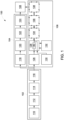
- FIG. 1 is a block flow diagram of an exemplary power generation system 100 that generates power using an alternative fuel, particularly ethanol.
- conventional fuels are typically fossil fuels, such as, but not limited to, petroleum products, coal, and/or natural gas.
- system 100 may also generate power using conventional fuels, such as, but not limited to, petroleum products, coal, and/or natural gas (methane).
- power generation system 100 includes a storage and distribution system 102, a liquid supply system 104, a vapor supply system 106, and a combustion system 108.
- Storage and distribution system 102 stores a volume of ethanol and channels a portion of the stored ethanol to liquid supply system 104 and to vapor supply system 106.
- Liquid supply system 104 receives liquid ethanol from storage and distribution system 102 and channels the liquid ethanol to combustion system 108.
- Vapor supply system 106 receives liquid ethanol from storage and distribution system 102, vaporizes the liquid ethanol into a vapor ethanol, and channels the vapor ethanol to combustion system 108. Additionally, vapor supply system 106 may also channel vapor methane to combustion system 108.
- Combustion system 108 generates power by combusting the liquid ethanol from liquid supply system 104, the vapor ethanol from vapor supply system 106, and/or a different fuel from either liquid supply system 104 or vapor supply system 106.
- storage and distribution system 102 includes an ethanol storage system 110, a first pump system 112, a first filtration system 114, and a first flow measurement system 116.
- Ethanol storage system 110 includes at least one storage tank (not shown) that receives and stores a volume of ethanol. Ethanol storage system 110 may receive ethanol from a pipeline, a nearby production facility, a ship, and/or a tanker truck, for example.
- First pump system 112 transfers ethanol from ethanol storage system 110 to first filtration system 114, to first flow measurement system 116, to liquid supply system 104, and/or to vapor supply system 106.
- first pump system 112 includes a pump.
- first pump system 112 includes any type of fluid motive device that enables storage and distribution system 102 to operate as described herein.
- first filtration system 114 filters particle and/or debris from the ethanol received from first pump system 112 to facilitate protecting downstream equipment from such particles and/or debris that may be entrained within the ethanol received from first pump system 112.
- First filtration system 114 may include any type of filter that enables storage and distribution system 102 to operate as described herein.
- first flow measurement system 116 measures the ethanol from first pump system 112 in order to better control liquid supply system 104 and/or vapor supply system 106.
- First flow measurement system 116 may include any type of flowmeter that enables storage and distribution system 102 to operate as described herein. Ethanol is channeled from first flow measurement system 116 to liquid supply system 104 and/or vapor supply system 106.
- liquid supply system 104 includes a second pump system 118, a second filtration system 120, a second flow measurement system 122, and a flow control and distribution system 124.
- Second pump system 118 transfers ethanol from first flow measurement system 116 to second filtration system 120, to second flow measurement system 122, to flow control and distribution system 124, and/or to combustion system 108.
- second pump system 118 includes a pump.
- second pump system 118 includes any type of fluid motive device that enables liquid supply system 104 to operate as described herein.
- second filtration system 120 filters particles and/or debris from the ethanol received from second pump system 118 to protect downstream equipment from such particles and/or debris that may be entrained within the ethanol received from second pump system 118.
- Second filtration system 120 may include any type of filter that enables liquid supply system 104 to operate as described herein.
- Liquid supply system 104 may also include a Safety Shutoff Valve (SSOV) to protect the equipment within liquid supply system 104 and/or combustion system 108.
- SSOV Safety Shutoff Valve
- second flow measurement system 122 measures the ethanol from second pump system 118 in order to control liquid supply system 104 and/or combustion system 108.
- Second flow measurement system 122 may include any type of flowmeter that enables liquid supply system 104 to operate as described herein.
- flow control and distribution system 124 controls the ethanol from flow measurement system 122 to combustion system 108.
- Flow control and distribution system 124 includes valves, actuators, and/or other flow control equipment that controls delivery or flow rate of ethanol to combustion system 108. Ethanol is channeled from flow control and distribution system 124 to combustion system 108.
- vapor supply system 106 includes a third pump system 126, a vaporization system 128, a methane supply system 130, a heat recovery steam generator (HRSG) 132, an inertial separator 134, a third flow measurement system 136, and a gas control system 138.
- Third pump system 126 transfers ethanol from first flow measurement system 116 to vaporization system 128, to inertial separator 134, to third flow measurement system 136, to gas control system 138, and/or to combustion system 108.
- third pump system 126 includes a pump.
- third pump system 126 includes any type of fluid motive device that enables vapor supply system 106 to operate as described herein.
- vaporization system 128 vaporizes the ethanol from third pump system 126.
- Vaporization system 128 includes at least one heat exchanger 140 that transfers heat from a heat exchange medium from HRSG 132 to the ethanol from third pump system 126 to cause the ethanol from third pump system 126 to vaporize.
- vaporization system 128 includes a plurality of heat exchangers 140 that vaporize the ethanol from third pump system 126.
- components of vaporization system 128 downstream of heat exchangers 140 are heat traced (as indicated by parallel hash marks on FIG. 1 ) to preheat equipment within vaporization system 128 in order to receive vaporized ethanol from heat exchangers 140. Heat tracing within vaporization system 128 may also be used to preheat equipment within vaporization system 128 in order to receive methane from methane supply system 130.
- methane supply system 130 channels methane into vaporization system 128 downstream from heat exchanger 140.
- the heating value of methane is similar to the heating value of ethanol, such that combustion system 108 is able to combust either ethanol vapor or methane.
- methane can be used as an alternate fuel source if ethanol is not available.
- methane supply system 130 supplies combustion system 108 with methane if ethanol is not available.
- methane supply system 130 may supply methane to supplement the vaporized ethanol. Accordingly, methane supply system 130 increases the operational flexibility of power generation system 100.
- HRSG 132 receives exhaust gases from combustion system 108 and transfers heat from the exhaust gases to a heat exchange medium. HRSG 132 also channels a heat exchange medium to heat exchangers 140 and receives a heat exchange medium from heat exchangers 140. In the exemplary embodiment, HRSG 132 includes a heat exchanger that recovers heat from the exhaust gases from combustion system 108 and transfers the recovered heat to a heat exchange medium. In the exemplary embodiment, the heat exchange medium includes liquid water and/or steam. However, the heat exchange medium may include any type of heat transfer fluid that enables vapor supply system 106 to operate as described herein.
- HRSG 132 and heat exchangers 140 form a closed loop circuit that channels the heat exchange medium from HRSG 132 and heat exchangers 140 and from heat exchangers 140 back to HRSG 132.
- HRSG 132 increases the temperature of the heat exchange medium by transferring heat from the exhaust gases to the heat exchange medium
- heat exchangers 140 decrease the temperature of the heat exchange medium by transferring heat from the heat exchange medium to the ethanol to vaporize the ethanol.
- inertial separator 134 separates liquids that may be entrained in the vaporized ethanol from vapor ethanol.
- the vaporized ethanol from vaporization system 128 may include liquids entrained in the vapor ethanol.
- liquid ethanol droplets may be entrained in the vaporized ethanol and/or the heat exchange medium may leak into the vaporized ethanol because of a failure within heat exchangers 140.
- inertial separator 134 includes a centrifugal separator.
- inertial separator 134 may include any other type of separator that enables vapor supply system 106 to operate as described herein.
- components of inertial separator 134 downstream from heat exchangers 140 are heat traced (as indicated by parallel hash marks on FIG. 1 ) to preheat equipment within inertial separator 134 in order to receive vaporized ethanol from heat exchangers 140.
- third flow measurement system 136 measures the vaporized ethanol from inertial separator 134 in order to control vapor supply system 106 and/or combustion system 108.
- Third flow measurement system 136 measures the flow of vaporized ethanol but does not control the flow of vaporized ethanol. Flow measurement is used for tabulating or totaling flow consumption when operating only on ethanol vapor or can be used as a method of controlling mixture or blend ratios during periods of operation when mixtures of both methane and ethanol vapor are used.
- Third flow measurement system 136 may include any type of flowmeter that enables vapor supply system 106 to operate as described herein.
- gas control system 138 controls the vaporized ethanol from third flow measurement system 136 to combustion system 108.
- Gas control system 138 includes valves, actuators, and/or other flow control equipment oriented to control the vaporized ethanol to combustion system 108.
- the vaporized ethanol is channeled from gas control system 138 to combustion system 108.
- components of third flow measurement system 136 and gas control system 138 downstream from heat exchangers 140 are heat traced (as indicated by parallel hash marks on FIG. 1 ) to preheat equipment within third flow measurement system 136 and gas control system 138 in order to receive vaporized ethanol from heat exchangers 140.
- combustion system 108 is a gas turbine engine.
- combustion system 108 may be any other turbine engine and/or rotary machine, including, without limitation, a gas turbofan aircraft engine and/or other aircraft engine.
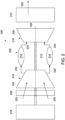
- FIG. 2 is an enlarged schematic view of an exemplary combustion system 108.
- combustion system 108 includes an intake section 202, a compressor section 204 that is downstream from intake section 202, a combustor section 206 that is downstream from compressor section 204, a turbine section 208 that is downstream from combustor section 206, and an exhaust section 210 that is downstream from turbine section 208.
- Turbine section 208 is coupled to compressor section 204 via a rotor shaft 212.
- the term "couple” is not limited to a direct mechanical, thermal, electrical, and/or flow communication connection between components but may also include an indirect mechanical, thermal, electrical, and/or flow communication connection between multiple components.
- combustor section 206 includes a plurality of combustors 214 and a plurality of fuel nozzles (not shown).
- Combustor section 206 is coupled to compressor section 204 such that each combustor 214 is in flow communication with the compressor section 204.
- Rotor shaft 212 is also coupled to a load 216 such as, but not limited to, an electrical generator and/or a mechanical drive application.
- each of compressor section 204 and turbine section 208 includes at least one rotor assembly 218 that is coupled to rotor shaft 212.
- intake section 202 channels air 220 towards compressor section 204.
- Compressor section 204 compresses inlet air 220 to higher pressures prior to discharging compressed air 222 towards combustor section 206.
- Compressed air 222 is channeled to combustor section 106 where it is mixed with the ethanol from liquid supply system 104 and/or the ethanol from vapor supply system 106 and burned to generate high temperature combustion gases 224. More specifically, the ethanol from liquid supply system 104 is channeled at a high pressure to the fuel nozzles. The fuel nozzles atomize the ethanol from liquid supply system 104 such that the atomized ethanol mixes with compressed air 222.
- Combustion gases 224 are channeled downstream towards turbine section 208 and impinge upon turbine blades (not shown), converting thermal energy to mechanical rotational energy that is used to drive rotor assembly 218 about a longitudinal axis 226. Often, combustor section 206 and turbine section 208 are referred to as a hot gas section of combustion system 108. Exhaust gases 228 are then discharged through exhaust section 210 to HRSG 132.
- storage and distribution system 102 channels ethanol to liquid supply system 104, and liquid supply system 104 channels the ethanol to combustion system 108.
- Combustion system 108 is ignited using liquid ethanol from liquid supply system 104. Accordingly, combustion system 108 is started using an alternative fuel. Exhaust gases 228 from combustion system 108 are channeled to HRSG 132.
- vapor supply system 106 begins vaporizing ethanol and channeling the vaporized ethanol to combustion system 108. That is, once the temperature of exhaust gases is high enough to vaporize ethanol, vapor supply system 106 begins vaporizing ethanol and channeling the vaporized ethanol to combustion system 108.
- Combustion system 108 then begins combusting liquid ethanol from liquid supply system 104 and vaporized ethanol from vapor supply system 106 during a transition period.
- Liquid supply system 104 reduces the volume of the liquid ethanol
- vapor supply system 106 increases the volume of the vaporized ethanol until combustion system 108 is combusting only vaporized ethanol. Accordingly, power generation system 100 ignites and operates combustion system 108 using an alternative fuel.
- methane supply system 130 channels methane into vaporization system 128 downstream of heat exchanger 140 such that the methane mixes with the vaporized ethanol. As such, the methane supplements the vaporized ethanol, and combustion system 108 operates on a mixture of vaporized ethanol and methane.
- methane supply system 130 channels methane into vaporization system 128 downstream of heat exchanger 140, and vaporization system 128 is not vaporizing ethanol. As such, combustion system 108 operates on methane only.
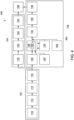
- FIG. 3 is a block flow diagram of an exemplary power generation system 300 that generates power with an alternative fuel and is ignited on methane only. More specifically, combustion system 108 is ignited using only methane, enabling exhaust gases 228 to heat HRSG 132. HRSG 132 increases the temperature of the heat exchange medium by transferring heat from the exhaust gases to the heat exchange medium, and heat exchangers 140 decrease the temperature of the heat exchange medium by transferring heat from the heat exchange medium to the ethanol to vaporize the ethanol. As such, combustion of the methane allows vaporization system 128 to begin producing vaporized ethanol. The vaporized ethanol is then blended with the methane, and combustion system 108 begins operating on a blend of methane and vaporized ethanol. Combustion system 108 either remains operating on the blend of methane and vaporized ethanol or switches over to operating on only vaporized ethanol.
- Power generation system 300 is substantially similar to power generation system 100 except, in power generation system 300, liquid supply system 104, vaporization system 128, inertial separator 134, third flow measurement system 136, and gas control system 138 do not include heat tracing.
- power generation system 300 may include liquid supply system 104 but liquid supply system 104 is idle during operation of power generation system 300.
- methane is channeled from methane supply system 130 through vaporization system 128, inertial separator 134, third flow measurement system 136, and gas control system 138 to combustion system 108.
- Combustion system 108 is ignited using methane from methane supply system 130.
- Exhaust gases 228 from combustion system 108 are channeled to HRSG 132.
- vapor supply system 106 begins vaporizing ethanol and channeling the vaporized ethanol to combustion system 108. That is, once the temperature of exhaust gases is high enough to vaporize ethanol, vapor supply system 106 begins vaporizing ethanol and channeling the vaporized ethanol to combustion system 108. More specifically, vapor supply system 106 mixes the vaporized ethanol with methane, and combustion system 108 then begins combusting the mixture of methane from methane supply system 130 and vaporized ethanol from vapor supply system 106 during a transition period.
- Methane supply system 130 reduces the volume of methane, and vapor supply system 106 increases the volume of the vaporized ethanol until combustion system 108 is combusting only vaporized ethanol. Accordingly, power generation system 300 ignites combustion system 108 using a conventional fuel (e.g., methane) and operates combustion system 108 using an alternative fuel (e.g., vaporized ethanol).
- a conventional fuel e.g., methane
- an alternative fuel e.g., vaporized ethanol
- Power generation system 300 may also include a steam pipe 302 coupled to HRSG 132 and inertial separator 134.
- combustion of methane generates exhaust gases 228 that heat HRSG 132.
- HRSG 132 generates steam that is channeled into inertial separator 134, third flow measurement system 136, and gas control system 138 to preheat equipment within inertial separator 134, third flow measurement system 136, and gas control system 138 in order to begin receiving vaporized ethanol from vaporization system 128.
- FIG. 4 is a block flow diagram of an exemplary power generation system 400 that generates power with an alternative fuel and that is ignited using liquid ethanol.
- Power generation system 400 is substantially similar to power generation system 300, except vapor supply system 106 also includes an auxiliary boiler 402, and steam pipe 302 is coupled to HRSG 132, auxiliary boiler 402, and inertial separator 134.
- Combustion system 108 is ignited using liquid ethanol, and auxiliary boiler 402 preheats equipment within inertial separator 134, third flow measurement system 136, and gas control system 138 in order to receive vaporized ethanol from vaporization system 128.
- auxiliary boiler 402 While auxiliary boiler 402 is preheating portions of vapor supply system 106, exhaust gases 228 heat HRSG 132. HRSG 132 increases the temperature of the heat exchange medium by transferring heat from the exhaust gases to the heat exchange medium, and heat exchangers 140 decrease the temperature of the heat exchange medium by transferring heat from the heat exchange medium to the ethanol to vaporize the ethanol. As such, combustion of the liquid ethanol allows vaporization system 128 to begin producing vaporized ethanol. The vaporized ethanol is then blended with the liquid ethanol and combustion system 108 begins operating on a blend of liquid ethanol and vaporized ethanol. Preheating portions of vapor supply system 106 with auxiliary boiler 402 enables vapor supply system 106 to quickly begin producing vaporized ethanol and to quickly switch to operating only on vaporized ethanol.
- steam pipe 302 channels steam from auxiliary boiler 402 and/or HRSG 132 into inertial separator 134.
- the steam preheats equipment within inertial separator 134, third flow measurement system 136, and gas control system 138 in order to receive vaporized ethanol from vaporization system 128.
- Auxiliary boiler 402 generates steam using electricity, combustion of natural gas, combustion of ethanol, and/or any other source of energy.
- Storage and distribution system 102 then channels ethanol to liquid supply system 104, and liquid supply system 104 channels the ethanol to combustion system 108.
- Combustion system 108 is ignited using liquid ethanol from liquid supply system 104. Accordingly, combustion system 108 is started using an alternative fuel. Exhaust gases 228 from combustion system 108 are channeled to HRSG 132.
- vapor supply system 106 begins vaporizing ethanol and channeling the vaporized ethanol to combustion system 108. That is, once the temperature of exhaust gases is high enough to vaporize ethanol, vapor supply system 106 begins vaporizing ethanol and channeling the vaporized ethanol to combustion system 108. Combustion system 108 then begins combusting liquid ethanol from liquid supply system 104 and vaporized ethanol from vapor supply system 106 during a transition period. Liquid supply system 104 reduces the volume of the liquid ethanol, and vapor supply system 106 increases the volume of the vaporized ethanol until combustion system 108 is combusting only vaporized ethanol. Accordingly, power generation system 400 ignites and operates combustion system 108 using an alternative fuel.
- auxiliary boiler 402 During an alternative operational mode of power generation system 400, steam from auxiliary boiler 402 is channeled into inertial separator 134, third flow measurement system 136, and gas control system 138 to preheat equipment within inertial separator 134, third flow measurement system 136, and gas control system 138.
- methane is channeled from methane supply system 130 through vaporization system 128, inertial separator 134, third flow measurement system 136, and gas control system 138 to combustion system 108.
- Combustion system 108 is ignited using methane from methane supply system 130. Exhaust gases 228 from combustion system 108 are channeled to HRSG 132.
- vapor supply system 106 begins vaporizing ethanol and channeling the vaporized ethanol to combustion system 108. That is, once the temperature of exhaust gases is high enough to vaporize ethanol, vapor supply system 106 begins vaporizing ethanol and channeling the vaporized ethanol to combustion system 108. More specifically, vapor supply system 106 mixes the vaporized ethanol with methane, and combustion system 108 then begins combusting the mixture of methane from methane supply system 130 and vaporized ethanol from vapor supply system 106 during a transition period.
- Methane supply system 130 reduces the volume of the methane, and vapor supply system 106 increases the volume of the vaporized ethanol until combustion system 108 is combusting only vaporized ethanol. Accordingly, power generation system 400 ignites combustion system 108 using a conventional fuel (e.g., methane) and operates combustion system 108 using an alternative fuel (e.g., vaporized ethanol).
- a conventional fuel e.g., methane
- an alternative fuel e.g., vaporized ethanol
- FIG. 5 is a block flow diagram of an exemplary power generation system 500 that generates power with an alternative fuel.
- Power generation system 500 is substantially similar to power generation system 400, except vapor supply system 106 also includes a steam or water supply pipe 502 also coupled to auxiliary boiler 402 and heat exchangers 140 of vaporization system 128 and a steam or condensate return pipe 504 coupled to auxiliary boiler 402 and heat exchangers 140 of vaporization system 128.
- Steam or water supply pipe 502 channels steam or water from auxiliary boiler 402 to heat exchangers 140 of vaporization system 128 to vaporize the ethanol from third pump system 126.
- Steam or condensate return pipe 504 channels steam or condensate from heat exchangers 140 of vaporization system 128 back to auxiliary boiler 402.
- Auxiliary boiler 402 generates steam using electricity, combustion of natural gas, combustion of ethanol, and/or any other source of energy.
- auxiliary boiler 402 During operation of power generation system 500, steam from auxiliary boiler 402 is channeled to heat exchangers 140 of vaporization system 128. Simultaneously, third pump system 126 pumps liquid ethanol to vaporization system 128, and steam from auxiliary boiler 402 vaporizes the liquid ethanol.
- Storage and distribution system 102 then channels ethanol to liquid supply system 104, and liquid supply system 104 channels the ethanol to combustion system 108.
- Combustion system 108 is ignited using liquid ethanol from liquid supply system 104. Accordingly, combustion system 108 is started using an alternative fuel. Combustion system 108 then begins combusting liquid ethanol from liquid supply system 104 and vaporized ethanol from vapor supply system 106 during a transition period.
- Liquid supply system 104 reduces the volume of the liquid ethanol, and vapor supply system 106 increases the volume of the vaporized ethanol until combustion system 108 is combusting only vaporized ethanol. Exhaust gases 228 from combustion system 108 are channeled to HRSG 132.
- HRSG 132 begins channeling steam to vaporization system 128, and auxiliary boiler 402 reduces production of steam until HRSG 132 is producing all steam necessary to vaporize the liquid ethanol. Accordingly, power generation system 500 ignites and operates combustion system 108 using an alternative fuel.
- steam from auxiliary boiler 402 is channeled into inertial separator 134, third flow measurement system 136, and gas control system 138 by steam pipe 302 to preheat equipment within inertial separator 134, third flow measurement system 136, and gas control system 138.
- Steam from auxiliary boiler 402 is also channeled to heat exchangers 140 of vaporization system 128 to vaporize the ethanol from third pump system 126 using steam supply pipe 502.
- Vapor supply system 106 vaporizes the ethanol and channels the vaporized ethanol to combustion system 108.
- Combustion system 108 is then ignited and operated using vaporized ethanol from vapor supply system 106. Accordingly, combustion system 108 is started using a vaporized alternative fuel.
- Exhaust gases 228 from combustion system 108 are channeled to HRSG 132.
- HRSG 132 begins channeling steam to vapor supply system 106. That is, once the temperature of exhaust gases is high enough to vaporize ethanol, HRSG 132 begins channeling steam to vapor supply system 106 and vapor supply system 106 begins vaporizing ethanol using the steam from HRSG 132. Combustion system 108 then begins combusting vaporized ethanol that has been vaporized using steam from HRSG 132 rather than auxiliary boiler 402. Accordingly, power generation system 500 ignites and operates combustion system 108 using a vaporized alternative fuel.
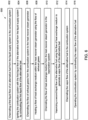
- FIG. 6 is a flow diagram of an exemplary method 600 of generating power using power generation system 100 (shown in FIG. 1 ).
- Power generation system 100 includes combustion system 108, liquid supply system 104, and vapor supply system 106.
- Vapor supply system 106 includes HRSG 132 and vaporization system 128.
- method 600 includes channeling 602 a first liquid alternative fuel from liquid supply system 104 to combustion system 108.
- Method 600 also includes igniting 604 combustion system 108 with the first liquid alternative fuel from liquid supply system 104 by combusting the first liquid alternative fuel. Combustion of the first liquid alternative fuel generates power and exhaust gases.
- Method 600 further includes channeling 606 the exhaust gases from combustion system 108 to HRSG 132.
- Method 600 also includes heating 608 a heat exchange medium within HRSG 132 using the exhaust gases. Method 600 further includes channeling 610 the heat exchange medium from HRSG 132 to vaporization system 106. Method 600 also includes vaporizing 612 a second liquid alternative fuel using the heat exchange medium to generate a vapor alternative fuel. Method 600 further includes channeling 614 the vapor alternative fuel to combustion system 108. Method 600 also includes operating 616 combustion system 108 by combusting the vapor alternative fuel.
- FIG. 7 is a flow diagram of an exemplary method 700 of generating power using power generation system 500 (shown in FIG. 5 ).
- Power generation system 500 includes combustion system 108 and vapor supply system 106.
- Vapor supply system 106 includes vaporization system 128 and auxiliary boiler 402.
- Method 700 includes generating 702 steam using auxiliary boiler 402.
- Method 700 also includes channeling 704 the steam from auxiliary boiler 402 to vaporization system 106.
- Method 700 further includes vaporizing 706 a liquid alternative fuel using the steam to generate a vapor alternative fuel.
- Method 700 also includes channeling 708 the vapor alternative fuel to combustion system 108.
- Method 700 further includes igniting and operating 710 combustion system 108 by combusting the vapor alternative fuel.
- the power generation system described herein includes a storage and distribution system, a liquid supply system, a vapor supply system, and a combustion system.
- the storage and distribution system stores a volume of an alternative fuel, such as ethanol, and channels a portion of the stored ethanol to the liquid supply system and to the vapor supply system.
- the liquid supply system receives liquid ethanol from the storage and distribution system and channels the liquid ethanol to the combustion system.
- the vapor supply system receives ethanol from the storage and distribution system, vaporizes the liquid ethanol into a vapor ethanol that is channeled to the combustion system.
- the combustion system generates power by igniting the liquid ethanol from the liquid supply system.
- Exhaust gases from the combustion system are then channeled to a heat recovery steam generator within the vapor supply system, where the heat recovery steam generator generates steam that is channeled to heat exchangers within the vapor supply system.
- the heat exchangers vaporize the liquid ethanol into a vaporized ethanol that is channeled to the combustion system.
- the combustion system initiates combusting liquid ethanol from the liquid supply system and, during a transition period, operates using liquid ethanol and vaporized ethanol from the vapor supply system. More specifically, the liquid supply system reduces the volume of the liquid ethanol, and the vapor supply system increases the volume of the vaporized ethanol until the combustion system is combusting only vaporized ethanol. Accordingly, the power generation system described herein ignites and subsequently is operated using an alternative fuel. Typically, power generation systems that generate power using alternative fuels emit less greenhouse gases and have greater operational flexibility than power generation systems that generate power using conventional fuels. Accordingly, the power generation systems described herein facilitate reducing fossil fuel emissions and have greater operational flexibility by generating power with alternative fuels such as ethanol.
- an exemplary technical effect of the systems and methods described herein includes at least one of: (a) igniting a combustion system using a liquid alternative fuel; (b) igniting a combustion system using a vapor alternative fuel; and (c) operating a combustion system using a vapor alternative fuel.
- Exemplary embodiments of systems and methods for generating power using an alternative fuel are described above in detail.
- the methods and systems are not limited to the specific embodiments described herein, but rather, components of systems and/or steps of the methods may be utilized independently and separately from other components and/or steps described herein.
- the method may also be used in combination with other power generation systems and are not limited to practice only with the other power generation systems as described herein. Rather, the exemplary embodiment can be implemented and utilized in connection with many other power generation applications.
Landscapes
- Engineering & Computer Science (AREA)
- Chemical & Material Sciences (AREA)
- Combustion & Propulsion (AREA)
- Mechanical Engineering (AREA)
- General Engineering & Computer Science (AREA)
- Engine Equipment That Uses Special Cycles (AREA)
- Output Control And Ontrol Of Special Type Engine (AREA)
Claims (8)
- Leistungserzeugungssystem (100), umfassend:ein Gasturbinentriebwerk (108), das konfiguriert ist, um durch ein Verbrennen von Ethanol Leistung zu erzeugen;ein Flüssigethanol-Zufuhrsystem (104), das konfiguriert ist, um Flüssigethanol zu dem Gasturbinentriebwerk (108) zu leiten;ein Dampfethanol-Zufuhrsystem (106), das konfiguriert ist, um verdampftes Ethanol zu dem Gasturbinentriebwerk (108) zu leiten; undein Ethanol-Speichersystem (110), das konfiguriert ist, um Flüssigethanol zu dem Flüssigethanol-Zufuhrsystem (104) und zu dem Dampfethanol-Zufuhrsystem (106) zu leiten;wobei:das Gasturbinentriebwerk konfiguriert ist, um gezündet zu werden und durch das Verbrennen des Flüssigethanols Leistung und Abgase zu erzeugen;das Dampfethanol-Zufuhrsystem (106) einen Wärmegewinnungswasserdampferzeuger (132) umfasst und konfiguriert ist, um die Abgase von dem Gasturbinentriebwerk (108) zu dem Wärmegewinnungswasserdampferzeuger (132) zu leiten und ein Tauschmedium innerhalb des Wärmegewinnungswasserdampferzeugers (132) unter Verwendung der Abgase zu erwärmen;das Dampfethanol-Zufuhrsystem (106) ferner einen Wärmetauscher (140) umfasst und konfiguriert ist, um das Wärmetauschmedium von dem Wärmegewinnungswasserdampferzeuger (132) zu dem Wärmetauscher (140) zu leiten;der Wärmetauscher (140) konfiguriert ist, um Flüssigethanol unter Verwendung des Wärmetauschmediums zu verdampfen, um das verdampfte Ethanol zu erzeugen; unddas Leistungserzeugungssystem ferner konfiguriert ist, um das verdampfte Ethanol zu dem Gasturbinentriebwerk (108) zu leiten und das Gasturbinentriebwerk (108) durch das Verbrennen des verdampften Ethanols zu betreiben;wobei nach dem Zünden (604) des Gasturbinentriebwerks (108) mit dem Flüssigethanol das Flüssigethanol-Zufuhrsystem (104) konfiguriert ist, um das Volumen von Flüssigethanol zu verringern, das dem Gasturbinentriebwerk (108) zugeführt wird, und das Dampfethanol-Zufuhrsystem (106) konfiguriert ist, um das Volumen von verdampftem Ethanol zu erhöhen, das dem Gasturbinentriebwerk (108) zugeführt wird, bis das Gasturbinentriebwerk nur noch verdampftes Ethanol verbrennt.
- Leistungserzeugungssystem (100) nach Anspruch 1, wobei das Gasturbinentriebwerk (108) einen Brennkammerabschnitt (206) umfasst, umfassend eine Vielzahl von Brennkammern (214) und eine Vielzahl von Brennstoffdüsen, wobei die Vielzahl von Brennstoffdüsen konfiguriert ist, um das Flüssigethanol zu zerstäuben und das zerstäubte Flüssigethanol in die Vielzahl von Brennkammern (214) einzuspritzen.
- Verfahren (600) für eine Leistungserzeugung unter Verwendung eines Leistungserzeugungssystems (100), wobei das Leistungserzeugungssystem (100) ein Gasturbinentriebwerk (108), ein Ethanol-Speichersystem (110), ein Flüssigethanol-Zufuhrsystem (104) und ein Dampfethanol-Zufuhrsystem (106) umfasst, wobei das Dampfethanol-Zufuhrsystem (106) einen Wärmegewinnungswasserdampferzeuger (132) und einen Wärmetauscher (140) umfasst, wobei das Verfahren (600) umfasst:Leiten (602) von Flüssigethanol von dem Ethanol-Speichersystem (110) zu dem Flüssigethanol-Zufuhrsystem (104) und weiter zu dem Gasturbinentriebwerk (108);Zünden (604) des Gasturbinentriebwerks (108) mit dem Flüssigethanol aus dem Flüssigethanol-Zufuhrsystem (104) durch das Verbrennen des Flüssigethanols, um Leistung und Abgase zu erzeugen;Leiten (606) der Abgase aus dem Gasturbinentriebwerk (108) zu dem Wärmegewinnungswasserdampferzeuger (132);Erwärmen (608) eines Wärmetauschmediums innerhalb des Wärmegewinnungswasserdampferzeugers (132) unter Verwendung der Abgase;Leiten (610) des Wärmetauschmediums von dem Wärmegewinnungswasserdampferzeuger (132) zu dem Wärmetauscher (140);Leiten von Flüssigethanol von dem Ethanol-Speichersystem (110) zu dem Dampfethanol-Zufuhrsystem (106);Verdampfen (612) von Flüssigethanol in dem Wärmetauscher (140) unter Verwendung des Wärmetauschmediums, um verdampftes Ethanol zu erzeugen;Leiten (614) des verdampften Ethanols zu dem Gasturbinentriebwerk (108); undBetreiben (616) des Gasturbinentriebwerks (108) durch das Verbrennen des verdampften Ethanols;wobei nach dem Zünden (604) des Gasturbinentriebwerks (108) mit dem Flüssigethanol das Flüssigethanol-Zufuhrsystem (104) das Volumen von Flüssigethanol, verringert, das dem Gasturbinentriebwerk (108) zugeführt wird, und das Dampfethanol-Zufuhrsystem (106) das Volumen von verdampftem Ethanol erhöht, das dem Gasturbinentriebwerk (108) zugeführt wird, bis das Gasturbinentriebwerk nur noch verdampftes Ethanol verbrennt.
- Verfahren (600) nach Anspruch 3, wobei das Gasturbinentriebwerk (108) einen Verbrennungsabschnitt (206) umfasst, umfassend eine Vielzahl von Brennkammern (214) und eine Vielzahl von Brennstoffdüsen, wobei das Verfahren (600) ferner das Zerstäuben des Flüssigethanols unter Verwendung der Vielzahl von Brennstoffdüsen umfasst.
- Verfahren (600) nach Anspruch 3, ferner umfassend das Leiten des verdampften Ethanols zu einem Trägheitsabscheider (134).
- Verfahren (600) nach Anspruch 5, wobei der Trägheitsabscheider (134) einen Zentrifugalabscheider umfasst, wobei das Verfahren (600) ferner das Abscheiden von mitgerissenen Flüssigkeiten in dem Verdampften unter Verwendung des Trägheitsabscheiders (134) umfasst.
- Verfahren (600) nach Anspruch 3, ferner umfassend das Vorwärmen des Dampfethanol-Zufuhrsystems (106) unter Verwendung eines Wärmetauschmediums aus dem Wärmegewinnungswasserdampferzeuger (132).
- Verfahren (600) nach Anspruch 3, wobei das Erwärmen eines Wärmetauschmediums innerhalb des Wärmegewinnungswasserdampferzeugers (132) unter Verwendung der Abgase das Erwärmen von Wasserdampf innerhalb des Wärmegewinnungswasserdampferzeugers (132) unter Verwendung der Abgase umfasst.
Applications Claiming Priority (1)
| Application Number | Priority Date | Filing Date | Title |
|---|---|---|---|
| US16/723,161 US11629642B2 (en) | 2019-12-20 | 2019-12-20 | System and methods for igniting and operating a gas turbine engine with alternative fuels |
Publications (2)
| Publication Number | Publication Date |
|---|---|
| EP3839228A1 EP3839228A1 (de) | 2021-06-23 |
| EP3839228B1 true EP3839228B1 (de) | 2025-02-19 |
Family
ID=73726706
Family Applications (1)
| Application Number | Title | Priority Date | Filing Date |
|---|---|---|---|
| EP20211967.3A Active EP3839228B1 (de) | 2019-12-20 | 2020-12-04 | System und verfahren zum zünden und betreiben eines gasturbinenmotors mit alternativen brennstoffen |
Country Status (4)
| Country | Link |
|---|---|
| US (1) | US11629642B2 (de) |
| EP (1) | EP3839228B1 (de) |
| JP (1) | JP7669142B2 (de) |
| CN (1) | CN113006939B (de) |
Cited By (1)
| Publication number | Priority date | Publication date | Assignee | Title |
|---|---|---|---|---|
| US20260022664A1 (en) * | 2024-07-18 | 2026-01-22 | General Electric Company | Fuel thermal management systems and related methods |
Families Citing this family (4)
| Publication number | Priority date | Publication date | Assignee | Title |
|---|---|---|---|---|
| KR20240138523A (ko) * | 2022-03-07 | 2024-09-20 | 가부시키가이샤 아이에이치아이 | 가스 터빈 시스템 |
| AU2022446945B2 (en) * | 2022-03-16 | 2025-12-18 | Ihi Corporation | Gas turbine system |
| US12092036B2 (en) * | 2022-12-21 | 2024-09-17 | Ge Infrastructure Technology Llc | Alternative fuel fast start systems for gas turbine engines |
| US12422798B1 (en) * | 2024-10-10 | 2025-09-23 | Huaneng (Tianjin) Gas Power Co., Ltd. | Process adjustment control method and syetem based on production line co-production |
Citations (1)
| Publication number | Priority date | Publication date | Assignee | Title |
|---|---|---|---|---|
| US20130219900A1 (en) * | 2012-02-28 | 2013-08-29 | Hitachi, Ltd. | Gas Turbine Combustor |
Family Cites Families (26)
| Publication number | Priority date | Publication date | Assignee | Title |
|---|---|---|---|---|
| US4380975A (en) * | 1981-04-06 | 1983-04-26 | General Motors Corporation | Cold starting system for alcohol fueled engine |
| JPH09505655A (ja) | 1993-11-24 | 1997-06-03 | ユナイテッド テクノロジーズ コーポレイション | 冷却されたタービン用翼型 |
| JPH0828304A (ja) * | 1994-07-12 | 1996-01-30 | Toshiba Corp | ガスタービンプラント |
| US5617716A (en) * | 1994-09-16 | 1997-04-08 | Electric Power Research Institute | Method for supplying vaporized fuel oil to a gas turbine combustor and system for same |
| US5669759A (en) | 1995-02-03 | 1997-09-23 | United Technologies Corporation | Turbine airfoil with enhanced cooling |
| DE19744456A1 (de) * | 1997-10-08 | 1999-01-28 | Siemens Ag | Gasturbinenanlage und Gas- und Dampfturbinenanlage mit einer derartigen Gasturbinenanlage sowie Verfahren zum Betreiben einer derartigen Gasturbinenanlage |
| US6105370A (en) * | 1998-08-18 | 2000-08-22 | Hamilton Sundstrand Corporation | Method and apparatus for rejecting waste heat from a system including a combustion engine |
| US6435814B1 (en) | 2000-05-16 | 2002-08-20 | General Electric Company | Film cooling air pocket in a closed loop cooled airfoil |
| US6939392B2 (en) * | 2003-04-04 | 2005-09-06 | United Technologies Corporation | System and method for thermal management |
| US6955522B2 (en) | 2003-04-07 | 2005-10-18 | United Technologies Corporation | Method and apparatus for cooling an airfoil |
| US7654073B2 (en) | 2003-12-11 | 2010-02-02 | Primlani Indru J | Power generating systems and methods |
| US7827794B1 (en) | 2005-11-04 | 2010-11-09 | Clean Energy Systems, Inc. | Ultra low emissions fast starting power plant |
| US7303372B2 (en) | 2005-11-18 | 2007-12-04 | General Electric Company | Methods and apparatus for cooling combustion turbine engine components |
| CA2654795C (en) | 2006-06-13 | 2014-08-26 | Monsanto Technology Llc | Reformed alcohol power systems |
| JP4963406B2 (ja) * | 2006-11-16 | 2012-06-27 | 一般財団法人電力中央研究所 | ガスタービン燃焼器並びにその運転方法 |
| US7568882B2 (en) | 2007-01-12 | 2009-08-04 | General Electric Company | Impingement cooled bucket shroud, turbine rotor incorporating the same, and cooling method |
| JP2011508139A (ja) | 2007-12-21 | 2011-03-10 | グリーン パートナーズ テクノロジー ホールディングス ゲゼルシャフト ミット ベシュレンクテル ハフツング | 気化性液体供給装置を採用するガスタービン・システム及び方法 |
| US8640465B2 (en) | 2008-07-03 | 2014-02-04 | Anagenesis Trees Corporation | Combined heat, ice, power, and steam system |
| US20110023491A1 (en) * | 2009-07-30 | 2011-02-03 | General Electric Company | System and method for supplying fuel to a gas turbine |
| EP2547888A4 (de) | 2010-03-15 | 2016-03-16 | Ener Core Power Inc | Verarbeitung von kraftstoff und wasser |
| CN102597459B (zh) * | 2010-06-03 | 2015-06-17 | 松下电器产业株式会社 | 燃气轮机系统 |
| US9151173B2 (en) | 2011-12-15 | 2015-10-06 | General Electric Company | Use of multi-faceted impingement openings for increasing heat transfer characteristics on gas turbine components |
| US20130186057A1 (en) * | 2012-01-25 | 2013-07-25 | Venkadesh Shanmugam | Naphtha and process gas/syngas mixture firing method for gas turbine engines |
| US9289826B2 (en) | 2012-09-17 | 2016-03-22 | Honeywell International Inc. | Turbine stator airfoil assemblies and methods for their manufacture |
| US9347376B2 (en) | 2013-04-24 | 2016-05-24 | General Electric Company | Liquified fuel backup fuel supply for a gas turbine |
| US10100748B2 (en) * | 2014-09-15 | 2018-10-16 | The Boeing Company | Dual fuel gas turbine thrust and power control |
-
2019
- 2019-12-20 US US16/723,161 patent/US11629642B2/en active Active
-
2020
- 2020-11-30 JP JP2020198075A patent/JP7669142B2/ja active Active
- 2020-12-03 CN CN202011405571.5A patent/CN113006939B/zh active Active
- 2020-12-04 EP EP20211967.3A patent/EP3839228B1/de active Active
Patent Citations (1)
| Publication number | Priority date | Publication date | Assignee | Title |
|---|---|---|---|---|
| US20130219900A1 (en) * | 2012-02-28 | 2013-08-29 | Hitachi, Ltd. | Gas Turbine Combustor |
Cited By (1)
| Publication number | Priority date | Publication date | Assignee | Title |
|---|---|---|---|---|
| US20260022664A1 (en) * | 2024-07-18 | 2026-01-22 | General Electric Company | Fuel thermal management systems and related methods |
Also Published As
| Publication number | Publication date |
|---|---|
| JP7669142B2 (ja) | 2025-04-28 |
| US11629642B2 (en) | 2023-04-18 |
| CN113006939B (zh) | 2025-09-23 |
| EP3839228A1 (de) | 2021-06-23 |
| US20210189965A1 (en) | 2021-06-24 |
| JP2021099096A (ja) | 2021-07-01 |
| CN113006939A (zh) | 2021-06-22 |
Similar Documents
| Publication | Publication Date | Title |
|---|---|---|
| US11629642B2 (en) | System and methods for igniting and operating a gas turbine engine with alternative fuels | |
| EP3978738B1 (de) | Wasserstoffbrennstoffverdampfer | |
| US11603798B1 (en) | Cryogenically assisted exhaust condensation | |
| US11753993B1 (en) | Turbine engine with mass rejection | |
| US10989117B2 (en) | Hybrid expander cycle with pre-compression cooling and turbo-generator | |
| US9347376B2 (en) | Liquified fuel backup fuel supply for a gas turbine | |
| CA2514073C (en) | Thermodynamic cycles using thermal diluent | |
| EP2206903B1 (de) | Verfahren zur Regelung von Heizwert eines Brennstoffs | |
| US5617716A (en) | Method for supplying vaporized fuel oil to a gas turbine combustor and system for same | |
| US8858223B1 (en) | Glycerin fueled afterburning engine | |
| GB2195402A (en) | A method of power generation and it's use in a propulsion device | |
| US20110314833A1 (en) | Additive injection system for use with a turbine engine and methods of assembling same | |
| JP2017061933A (ja) | ガスタービンエンジン用の液化石油ガス燃料調整システム | |
| EP3336330B1 (de) | Verfahren zum anfahren und betreiben von gasturbinenkombikraftwerken mit nmhc-brennstoffen | |
| US12240624B1 (en) | Aircraft gas turbine engine with heated fuel to assist combustion | |
| US12523171B2 (en) | Flash-atomizing ammonia in a gas turbine combustor | |
| US20140298817A1 (en) | Arrangement for preparation of liquid fuel for combustion and a method of preparing liquid fuel for combustion | |
| US20140007553A1 (en) | Hot water injection for turbomachine | |
| US20110314832A1 (en) | Additive injection system for use with a turbine engine and methods of assembling same | |
| US20250251129A1 (en) | Gas turbine engine having a steam generating system providing steam to a combustor | |
| EP3832091B1 (de) | Gasturbinenanordnung für eine durch mindestens zwei verschiedene brennstoffe (brenngas oder brennöl) gespeiste kraftanlage und verfahren zum betrieb dieser anordnung beim umschalten von brennstoffen oder beim betrieb dieser anordnung mit brennöl |
Legal Events
| Date | Code | Title | Description |
|---|---|---|---|
| PUAI | Public reference made under article 153(3) epc to a published international application that has entered the european phase |
Free format text: ORIGINAL CODE: 0009012 |
|
| STAA | Information on the status of an ep patent application or granted ep patent |
Free format text: STATUS: THE APPLICATION HAS BEEN PUBLISHED |
|
| AK | Designated contracting states |
Kind code of ref document: A1 Designated state(s): AL AT BE BG CH CY CZ DE DK EE ES FI FR GB GR HR HU IE IS IT LI LT LU LV MC MK MT NL NO PL PT RO RS SE SI SK SM TR |
|
| STAA | Information on the status of an ep patent application or granted ep patent |
Free format text: STATUS: REQUEST FOR EXAMINATION WAS MADE |
|
| 17P | Request for examination filed |
Effective date: 20211220 |
|
| RBV | Designated contracting states (corrected) |
Designated state(s): AL AT BE BG CH CY CZ DE DK EE ES FI FR GB GR HR HU IE IS IT LI LT LU LV MC MK MT NL NO PL PT RO RS SE SI SK SM TR |
|
| STAA | Information on the status of an ep patent application or granted ep patent |
Free format text: STATUS: EXAMINATION IS IN PROGRESS |
|
| 17Q | First examination report despatched |
Effective date: 20230626 |
|
| RAP1 | Party data changed (applicant data changed or rights of an application transferred) |
Owner name: GENERAL ELECTRIC TECHNOLOGY GMBH |
|
| GRAP | Despatch of communication of intention to grant a patent |
Free format text: ORIGINAL CODE: EPIDOSNIGR1 |
|
| STAA | Information on the status of an ep patent application or granted ep patent |
Free format text: STATUS: GRANT OF PATENT IS INTENDED |
|
| INTG | Intention to grant announced |
Effective date: 20241023 |
|
| GRAS | Grant fee paid |
Free format text: ORIGINAL CODE: EPIDOSNIGR3 |
|
| GRAA | (expected) grant |
Free format text: ORIGINAL CODE: 0009210 |
|
| STAA | Information on the status of an ep patent application or granted ep patent |
Free format text: STATUS: THE PATENT HAS BEEN GRANTED |
|
| AK | Designated contracting states |
Kind code of ref document: B1 Designated state(s): AL AT BE BG CH CY CZ DE DK EE ES FI FR GB GR HR HU IE IS IT LI LT LU LV MC MK MT NL NO PL PT RO RS SE SI SK SM TR |
|
| REG | Reference to a national code |
Ref country code: GB Ref legal event code: FG4D |
|
| REG | Reference to a national code |
Ref country code: CH Ref legal event code: EP |
|
| REG | Reference to a national code |
Ref country code: IE Ref legal event code: FG4D |
|
| REG | Reference to a national code |
Ref country code: DE Ref legal event code: R096 Ref document number: 602020046247 Country of ref document: DE |
|
| REG | Reference to a national code |
Ref country code: NL Ref legal event code: MP Effective date: 20250219 |
|
| PG25 | Lapsed in a contracting state [announced via postgrant information from national office to epo] |
Ref country code: RS Free format text: LAPSE BECAUSE OF FAILURE TO SUBMIT A TRANSLATION OF THE DESCRIPTION OR TO PAY THE FEE WITHIN THE PRESCRIBED TIME-LIMIT Effective date: 20250519 |
|
| PG25 | Lapsed in a contracting state [announced via postgrant information from national office to epo] |
Ref country code: FI Free format text: LAPSE BECAUSE OF FAILURE TO SUBMIT A TRANSLATION OF THE DESCRIPTION OR TO PAY THE FEE WITHIN THE PRESCRIBED TIME-LIMIT Effective date: 20250219 |
|
| PG25 | Lapsed in a contracting state [announced via postgrant information from national office to epo] |
Ref country code: PL Free format text: LAPSE BECAUSE OF FAILURE TO SUBMIT A TRANSLATION OF THE DESCRIPTION OR TO PAY THE FEE WITHIN THE PRESCRIBED TIME-LIMIT Effective date: 20250219 |
|
| PG25 | Lapsed in a contracting state [announced via postgrant information from national office to epo] |
Ref country code: ES Free format text: LAPSE BECAUSE OF FAILURE TO SUBMIT A TRANSLATION OF THE DESCRIPTION OR TO PAY THE FEE WITHIN THE PRESCRIBED TIME-LIMIT Effective date: 20250219 |
|
| REG | Reference to a national code |
Ref country code: LT Ref legal event code: MG9D |
|
| PG25 | Lapsed in a contracting state [announced via postgrant information from national office to epo] |
Ref country code: NO Free format text: LAPSE BECAUSE OF FAILURE TO SUBMIT A TRANSLATION OF THE DESCRIPTION OR TO PAY THE FEE WITHIN THE PRESCRIBED TIME-LIMIT Effective date: 20250519 Ref country code: IS Free format text: LAPSE BECAUSE OF FAILURE TO SUBMIT A TRANSLATION OF THE DESCRIPTION OR TO PAY THE FEE WITHIN THE PRESCRIBED TIME-LIMIT Effective date: 20250619 |
|
| PG25 | Lapsed in a contracting state [announced via postgrant information from national office to epo] |
Ref country code: NL Free format text: LAPSE BECAUSE OF FAILURE TO SUBMIT A TRANSLATION OF THE DESCRIPTION OR TO PAY THE FEE WITHIN THE PRESCRIBED TIME-LIMIT Effective date: 20250219 |
|
| PG25 | Lapsed in a contracting state [announced via postgrant information from national office to epo] |
Ref country code: HR Free format text: LAPSE BECAUSE OF FAILURE TO SUBMIT A TRANSLATION OF THE DESCRIPTION OR TO PAY THE FEE WITHIN THE PRESCRIBED TIME-LIMIT Effective date: 20250219 |
|
| PG25 | Lapsed in a contracting state [announced via postgrant information from national office to epo] |
Ref country code: LV Free format text: LAPSE BECAUSE OF FAILURE TO SUBMIT A TRANSLATION OF THE DESCRIPTION OR TO PAY THE FEE WITHIN THE PRESCRIBED TIME-LIMIT Effective date: 20250219 Ref country code: PT Free format text: LAPSE BECAUSE OF FAILURE TO SUBMIT A TRANSLATION OF THE DESCRIPTION OR TO PAY THE FEE WITHIN THE PRESCRIBED TIME-LIMIT Effective date: 20250620 |
|
| PG25 | Lapsed in a contracting state [announced via postgrant information from national office to epo] |
Ref country code: GR Free format text: LAPSE BECAUSE OF FAILURE TO SUBMIT A TRANSLATION OF THE DESCRIPTION OR TO PAY THE FEE WITHIN THE PRESCRIBED TIME-LIMIT Effective date: 20250520 Ref country code: BG Free format text: LAPSE BECAUSE OF FAILURE TO SUBMIT A TRANSLATION OF THE DESCRIPTION OR TO PAY THE FEE WITHIN THE PRESCRIBED TIME-LIMIT Effective date: 20250219 |
|
| REG | Reference to a national code |
Ref country code: AT Ref legal event code: MK05 Ref document number: 1768467 Country of ref document: AT Kind code of ref document: T Effective date: 20250219 |
|
| PG25 | Lapsed in a contracting state [announced via postgrant information from national office to epo] |
Ref country code: SE Free format text: LAPSE BECAUSE OF FAILURE TO SUBMIT A TRANSLATION OF THE DESCRIPTION OR TO PAY THE FEE WITHIN THE PRESCRIBED TIME-LIMIT Effective date: 20250219 |
|
| RAP4 | Party data changed (patent owner data changed or rights of a patent transferred) |
Owner name: GE VERNOVA TECHNOLOGY GMBH |
|
| PG25 | Lapsed in a contracting state [announced via postgrant information from national office to epo] |
Ref country code: SM Free format text: LAPSE BECAUSE OF FAILURE TO SUBMIT A TRANSLATION OF THE DESCRIPTION OR TO PAY THE FEE WITHIN THE PRESCRIBED TIME-LIMIT Effective date: 20250219 |
|
| PG25 | Lapsed in a contracting state [announced via postgrant information from national office to epo] |
Ref country code: DK Free format text: LAPSE BECAUSE OF FAILURE TO SUBMIT A TRANSLATION OF THE DESCRIPTION OR TO PAY THE FEE WITHIN THE PRESCRIBED TIME-LIMIT Effective date: 20250219 |
|
| PG25 | Lapsed in a contracting state [announced via postgrant information from national office to epo] |
Ref country code: IT Free format text: LAPSE BECAUSE OF FAILURE TO SUBMIT A TRANSLATION OF THE DESCRIPTION OR TO PAY THE FEE WITHIN THE PRESCRIBED TIME-LIMIT Effective date: 20250219 |
|
| PG25 | Lapsed in a contracting state [announced via postgrant information from national office to epo] |
Ref country code: AT Free format text: LAPSE BECAUSE OF FAILURE TO SUBMIT A TRANSLATION OF THE DESCRIPTION OR TO PAY THE FEE WITHIN THE PRESCRIBED TIME-LIMIT Effective date: 20250219 |
|
| PG25 | Lapsed in a contracting state [announced via postgrant information from national office to epo] |
Ref country code: EE Free format text: LAPSE BECAUSE OF FAILURE TO SUBMIT A TRANSLATION OF THE DESCRIPTION OR TO PAY THE FEE WITHIN THE PRESCRIBED TIME-LIMIT Effective date: 20250219 Ref country code: CZ Free format text: LAPSE BECAUSE OF FAILURE TO SUBMIT A TRANSLATION OF THE DESCRIPTION OR TO PAY THE FEE WITHIN THE PRESCRIBED TIME-LIMIT Effective date: 20250219 |
|
| PG25 | Lapsed in a contracting state [announced via postgrant information from national office to epo] |
Ref country code: RO Free format text: LAPSE BECAUSE OF FAILURE TO SUBMIT A TRANSLATION OF THE DESCRIPTION OR TO PAY THE FEE WITHIN THE PRESCRIBED TIME-LIMIT Effective date: 20250219 |
|
| PG25 | Lapsed in a contracting state [announced via postgrant information from national office to epo] |
Ref country code: SK Free format text: LAPSE BECAUSE OF FAILURE TO SUBMIT A TRANSLATION OF THE DESCRIPTION OR TO PAY THE FEE WITHIN THE PRESCRIBED TIME-LIMIT Effective date: 20250219 |
|
| REG | Reference to a national code |
Ref country code: DE Ref legal event code: R097 Ref document number: 602020046247 Country of ref document: DE |
|
| PLBE | No opposition filed within time limit |
Free format text: ORIGINAL CODE: 0009261 |
|
| STAA | Information on the status of an ep patent application or granted ep patent |
Free format text: STATUS: NO OPPOSITION FILED WITHIN TIME LIMIT |
|
| PGFP | Annual fee paid to national office [announced via postgrant information from national office to epo] |
Ref country code: DE Payment date: 20251126 Year of fee payment: 6 |
|
| 26N | No opposition filed |
Effective date: 20251120 |