EP3841287B1 - Zylinderventilanordnung mit ventilfederentlüftungsvorrichtung - Google Patents
Zylinderventilanordnung mit ventilfederentlüftungsvorrichtung Download PDFInfo
- Publication number
- EP3841287B1 EP3841287B1 EP18762247.7A EP18762247A EP3841287B1 EP 3841287 B1 EP3841287 B1 EP 3841287B1 EP 18762247 A EP18762247 A EP 18762247A EP 3841287 B1 EP3841287 B1 EP 3841287B1
- Authority
- EP
- European Patent Office
- Prior art keywords
- channel
- sealing member
- venting
- valve
- pressure
- Prior art date
- Legal status (The legal status is an assumption and is not a legal conclusion. Google has not performed a legal analysis and makes no representation as to the accuracy of the status listed.)
- Active
Links
Images


Classifications
-
- F—MECHANICAL ENGINEERING; LIGHTING; HEATING; WEAPONS; BLASTING
- F01—MACHINES OR ENGINES IN GENERAL; ENGINE PLANTS IN GENERAL; STEAM ENGINES
- F01L—CYCLICALLY OPERATING VALVES FOR MACHINES OR ENGINES
- F01L9/00—Valve-gear or valve arrangements actuated non-mechanically
- F01L9/10—Valve-gear or valve arrangements actuated non-mechanically by fluid means, e.g. hydraulic
- F01L9/16—Pneumatic means
Definitions
- the invention relates to a cylinder valve assembly for an internal combustion engine arrangement, and to an internal combustion engine arrangement.
- the invention can be applied in combustion engine arrangements for various uses, including, but not limited to, passenger cars or heavy-duty vehicles.
- Heavy duty vehicles may, for example, include trucks, buses and construction equipment.
- trucks trucks, buses and construction equipment.
- the invention will be described with respect to a truck, the invention is not restricted to this particular vehicle, but may also be used in other vehicles such as a bus, or working machines, such as wheel loaders or excavators etc.
- An internal combustion engine typically has at least one cylinder, and a piston caused to move linearly in the cylinder by combustion events taking place inside the cylinder.
- the cylinder is generally provided with at least one inlet, and to allow exhaust gases to exit the cylinder, the cylinder is generally provided with at least one outlet.
- at least one inlet valve is typically provided to control flow through the inlet(s)
- at least one exhaust valve is typically provided to control flow through the outlet(s).
- the spring force can be controlled by varying the amount of gas being compressed in the valve spring arrangement.
- controlled leakage of gas from the valve spring cavity in which gas is being compressed during opening of the valve
- US 2017/0037750 discloses a combustion engine with a pneumatic valve return spring, in which the valve spring cavity is open during a first part of the valve stroke in the beginning of a valve opening sequence, and closed during a second part of the valve stroke in the end of a valve opening sequence.
- EP 1 577 508 describes a cylinder valve assembly according to the preamble of claim 1.
- An object of the invention is to provide for improved energy efficiency of an internal combustion engine arrangement including at least one pneumatic valve spring arrangement.
- a cylinder valve assembly for an internal combustion engine, comprising: a valve; a valve actuator for moving the valve; and a pneumatic valve spring arrangement including a first valve spring member and a second valve spring member defining a valve spring cavity, the second valve spring member being arranged to move in relation to the first valve spring member to compress gas in the valve spring cavity when the valve actuator moves the valve.
- the cylinder valve assembly further comprises a valve spring venting arrangement comprising: a first venting cavity portion in fluid flow connection with the valve spring cavity; a second venting cavity portion; a movable sealing member arranged to allow a pressure difference between a first gas pressure in the first venting cavity portion and a second gas pressure in the second venting cavity portion; a feedback channel allowing fluid flow from the first venting cavity portion to the second venting cavity portion; and a venting channel for gas exhaust from the valve spring venting arrangement, wherein the sealing member is configured to be movable between: a first sealing member position in which the sealing member is arranged in such a way that the sealing member prevents fluid flow from the first venting cavity portion through the venting channel; and a second sealing member position in which the sealing member is arranged in such a way that the sealing member allows fluid flow from the first venting cavity portion through the venting channel, wherein the valve spring venting arrangement further comprises an elastic member urging the sealing member to move from the second sealing member position towards the first sealing member position.
- sealing member is arranged and configured to allow fluid flow from the first venting cavity portion to the second venting cavity portion through the feedback channel both in the first sealing member position and the second sealing member position.
- the elastic member may advantageously be a coil spring.
- the present invention is based on the realization that the valve spring force can be changed with less gas leakage by providing a sealing member that is movable to allow leakage against a spring force which depends on the pressure in the valve spring cavity.
- the present inventors have realized that a delay in pressure build-up in the second venting cavity portion, together with the elastic member urging the sealing member to move from the second sealing member position towards the first sealing member position, provide for a leakage event in the beginning of each valve opening operation. This allows leakage of gas through a venting channel that may be dimensioned to also allow reliable passage of lubricant, such as oil, through the venting channel.
- valve spring venting arrangement in particular at least one of the feedback channel, the venting channel, and the elastic member, may advantageously be configured to allow a desired reduction of the valve spring pressure to occur gradually over a number of valve opening operations, such as over at least ten valve opening operations, or over at least one hundred valve opening operations.
- the sealing member may be configured to receive a first force resulting from the first gas pressure in the first venting cavity portion, and a second force resulting from the second gas pressure in the second venting cavity portion.
- the first force may be directed to urge the sealing member to move towards the second sealing member position
- the second force may be directed to urge the sealing member to move towards the first sealing member position
- the feedback channel, the sealing member, and the elastic member may be dimensioned in such a way that the sealing member is moved from the first sealing member position to the second sealing member position during a portion of the time when the valve actuator moves the valve.
- the first venting cavity portion may be in fluid flow connection with the valve spring cavity through a flow channel having a first minimum cross-sectional area; and the feedback channel may have a second minimum cross-section area smaller than the first minimum channel cross-section area.
- the feedback channel may be inclined upwards at least along a feedback channel segment starting from the first venting cavity portion. It may be advantageous to use gas with oil mist in the cylinder valve assembly for lubrication. When allowing gas to leak through the venting channel, oil should also be allowed to leak. In configurations where gas with oil mist is used, it may also be desirable to prevent oil from entering the second cavity portion. This may be achieved by the above-mentioned upwards inclining feedback channel.
- the cylinder valve assembly may advantageously further comprise a gas inlet for providing gas to said pneumatic valve spring arrangement.
- a gas inlet for providing gas to said pneumatic valve spring arrangement.
- the gas inlet may advantageously be provided with a check valve, to prevent gas from flowing out of the cylinder valve assembly through the gas inlet.
- the cylinder valve assembly may further comprise an inlet channel fluid flow connecting the inlet with the first venting cavity portion of the valve spring venting arrangement.
- the cylinder valve assembly may further comprise a counter-pressure channel fluid flow connected to the second venting cavity portion.
- the feedback channel may comprise the inlet channel, the counter-pressure channel, and a pressure-levelling channel fluid flow connecting the inlet channel and the counter-pressure channel.
- a cross-sectional area of the pressure-levelling channel may be smaller than a cross-sectional area of the inlet channel and a cross-sectional area of the counter-pressure channel.
- a first end of the pressure levelling channel fluid flow connected to the inlet channel may be at a lower vertical level than a second end of the pressure levelling channel fluid flow connected to the counter-pressure channel.
- the cylinder valve assembly may advantageously be included in an internal combustion engine arrangement, further comprising a cylinder having at least one inlet and at least one outlet; wherein the cylinder valve assembly is arranged to allow control of fluid flow through at least one inlet and/or outlet of said cylinder.
- the ICE arrangement may comprise a plurality of cylinders, such as four, six or eight cylinders. Furthermore, each cylinder may advantageously have at least two inlets and at least two outlets.
- aspects of the present invention thus relate to a cylinder valve assembly comprising a pneumatic valve spring arrangement including a first and a second valve spring member defining a valve spring cavity, and a valve spring venting arrangement comprising a first venting cavity portion in fluid flow connection with the valve spring cavity; a second venting cavity portion; a movable sealing member arranged to allow a pressure difference between the first venting cavity portion and the second venting cavity portion; a feedback channel fluid flow connecting the first venting cavity portion and the second venting cavity portion; and a venting channel.
- the sealing member is configured to be movable between a first sealing member position where the sealing member prevents fluid flow from the first venting cavity portion through the venting channel; and a second sealing member position where the sealing member allows fluid flow from the first venting cavity portion through the venting channel.
- the valve spring venting arrangement further comprises an elastic member urging the sealing member towards the first sealing member position.
- Fig 1 schematically shows a vehicle, here in the form of a truck 1, including an ICE arrangement 3 according to an example embodiment of the present invention.
- the ICE arrangement 3 comprises a control unit 5 for controlling operation of the ICE arrangement 3.
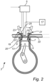
- the ICE arrangement 3 comprises a cylinder 7 having an inlet 9 and an outlet 11, a piston 13, a fuel supply member 15, a tank for holding fuel 17, a first cylinder valve assembly 19 for controlling flow through the inlet 9 using valve 20, and a second cylinder valve assembly 21 for controlling flow through the outlet 11 using valve 22.
- the first cylinder valve assembly 19 comprises valve 20, valve actuator 23, pneumatic valve spring arrangement 25, and valve spring venting arrangement 27.
- the second cylinder valve assembly 21 has the same general configuration.
- the control unit 5 is connected to, and configured to control operation of, the fuel supply member 15, the first cylinder valve assembly 19, and the second cylinder valve assembly 21.
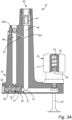
- the cylinder valve assembly 19 comprises a valve 20, a valve actuator (not shown in fig 3A ), a pneumatic valve spring arrangement 25, and a spring venting arrangement 27.
- the pneumatic valve spring arrangement includes a first valve spring member 29 and a second valve spring member 31, defining a valve spring cavity 33, and a coil spring 35.
- the coil spring 35 can be dimensioned to be relatively weak, and the main return force acting on the valve 20 when it is opened by the valve actuator may result from compression of the gas inside the valve spring cavity 33.
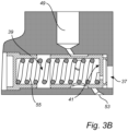
- the valve spring venting arrangement 27 comprises a first venting cavity portion 37 fluid flow connected with the valve spring cavity 33, a second venting cavity portion 39, a movable sealing member 41 arranged to allow a pressure difference between a first gas pressure P 1 in the first venting cavity portion 37 and a second gas pressure P 2 in the second venting cavity portion 39, a gas inlet 43, an inlet channel 45, a check valve 47, a counter-pressure channel 49, a pressure-levelling channel 51, a venting channel 53, and an elastic member 55.
- the inlet channel 45, the counter-pressure channel 49, and the pressure-levelling channel 51 together form a feedback channel fluid flow connecting the first venting cavity portion 37 and the second venting cavity portion 39.
- a first end 52a of the pressure levelling channel 51 fluid flow connected to the inlet channel 45 is at a lower vertical level than a second end 52b of the pressure levelling channel 51 fluid flow connected to the counter-pressure channel 51.
- a cross-sectional area of the pressure-levelling channel 51 is smaller than a cross-sectional area of the inlet channel 45 and a cross-sectional area of the counter-pressure channel 49.
- the first venting cavity portion 37 is in fluid flow connection with the valve spring cavity 33 through a flow channel having a first minimum cross-sectional area
- the feedback channel has a second minimum cross-section area smaller than the first minimum channel cross-sectional area.
- the second minimum cross-sectional area is the cross-sectional area of the pressure-levelling channel 51.
- the timing diagram 57 in fig 4 which is based on a simulation of the cylinder valve assembly 19 in figs 3A-B , includes a first curve 59 representing displacement of the valve 20 during an opening sequence of the valve 20, a second curve 61 representing the first gas pressure P 1 in the first venting cavity portion 37, a third curve 63 representing the second gas pressure P 2 in the second venting cavity portion 39, a fourth curve 65 representing displacement of the sealing member 41, and a fifth curve 67 representing flow through the venting channel 53.
- the variation of the first pressure P 1 (curve 61) follows the displacement of the valve 20 (curve 59) (and the corresponding pressure increase inside the valve spring cavity 33) with practically no delay.
- the variation of the second pressure P 2 (curve 63) is, however, delayed in relation to the first pressure P 1 (curve 61), due to the passage of gas through the feedback channel, which comprises the input channel 45, the counter-pressure channel 49, and the pressure-levelling channel 51 in the example configuration of figs 3A-B .
- the sealing member 41 moves away from the first sealing member position (the position shown in fig 3B ) to the second sealing member position, where a fluid passage between the first venting cavity portion 37 and the venting channel 53 is opened (towards the left in fig 3B ).
- this movement of the sealing member is represented by the fourth curve 65 in fig 4 .
Landscapes
- Engineering & Computer Science (AREA)
- Mechanical Engineering (AREA)
- General Engineering & Computer Science (AREA)
- Check Valves (AREA)
- General Details Of Gearings (AREA)
- Self-Closing Valves And Venting Or Aerating Valves (AREA)
Claims (12)
- Zylinderventilanordnung (19) für einen Verbrennungsmotor (3) umfassend:ein Ventil (20);einen Ventilantrieb (23) zum Bewegen des Ventils (20);eine pneumatische Ventilfederanordnung (25) mit einem ersten Ventilfederelement (29) und einem zweiten Ventilfederelement (31), die einen Ventilfederhohlraum (33) definieren, wobei das zweite Ventilfederelement (31) so angeordnet ist, dass es sich in Bezug auf das erste Ventilfederelement (29) bewegt, um Gas in dem Ventilfederhohlraum (33) zu komprimieren, wenn der Ventilantrieb (23) das Ventil (20) bewegt; undeine Ventilfederentlüftungsvorrichtung (27) umfassend:einen ersten Lüftungshohlraumabschnitt (37), der mit dem Ventilfederhohlraum (33) in Fluidströmungsverbindung steht;einen zweiten Lüftungshohlraumabschnitt (39);ein bewegliches Dichtungselement (41), das so angeordnet ist, dass es eine Druckdifferenz zwischen einem ersten Gasdruck (P1) in dem ersten Lüftungshohlraumabschnitt (37) und einem zweiten Gasdruck (P2) in dem zweiten Lüftungshohlraumabschnitt (39) ermöglicht;einen Lüftungskanal (53) für den Gasaustritt aus der Ventilfederentlüftungsvorrichtung (27),wobei das Dichtungselement (41) so konfiguriert ist, dass es beweglich ist zwischen:einer ersten Dichtungselementposition, in der das Dichtungselement (41) so angeordnet ist, dass das Dichtungselement (41) eine Fluidströmung von dem ersten Lüftungshohlraumabschnitt (37) durch den Lüftungskanal (53) verhindert; undeiner zweiten Dichtungselementposition, in der das Dichtungselement (41) so angeordnet ist, dass das Dichtungselement (41) eine Fluidströmung von dem ersten Lüftungshohlraumabschnitt (37) durch den Lüftungskanal (53) ermöglicht,wobei die Ventilfederentlüftungsvorrichtung (27) ferner ein elastisches Element (55) umfasst, das das Dichtungselement (41) dazu drängt, sich von der zweiten Dichtungselementposition in Richtung der ersten Dichtungselementposition zu bewegen,dadurch gekennzeichnet, dass die Ventilfederentlüftungsvorrichtung (27) einen Rückführungskanal umfasst, der eine Fluidströmung von dem ersten Lüftungshohlraumabschnitt (37) zu dem zweiten Lüftungshohlraumabschnitt (39) ermöglicht.
- Zylinderventilanordnung (19) nach Anspruch 1, wobei:das Dichtungselement (41) so konfiguriert ist, dass es eine erste Kraft aufnimmt, die aus dem ersten Gasdruck (P1) in dem ersten Lüftungshohlraumabschnitt (37) resultiert, und eine zweite Kraft, die aus dem zweiten Gasdruck (P2) in dem zweiten Lüftungshohlraumabschnitt (39) resultiert;die erste Kraft so gerichtet ist, dass sie das Dichtungselement (41) zur Bewegung in Richtung der zweiten Dichtungselementposition drängt, und die zweite Kraft so gerichtet ist, dass sie das Dichtungselement (41) zur Bewegung in Richtung der ersten Dichtungselementposition drängt; undder Rückführungskanal, das Dichtungselement (41) und das elastische Element (55) so dimensioniert sind, dass das Dichtungselement (41) während eines Teils der Zeit, in der der Ventilantrieb (23) das Ventil (20) bewegt, von der ersten Dichtungselementposition zur zweiten Dichtungselementposition bewegt wird.
- Zylinderventilanordnung (19) nach Anspruch 1 oder 2, wobei:der erste Lüftungshohlraumabschnitt (37) mit dem Ventilfederhohlraum (33) durch einen Strömungskanal mit einer ersten Mindestquerschnittsfläche in Fluidströmungsverbindung steht; undder Rückführungskanal eine zweite Mindestquerschnittsfläche aufweist, die kleiner ist als die erste Mindestkanalquerschnittsfläche.
- Zylinderventilanordnung (19) nach einem der vorhergehenden Ansprüche, ferner umfassend einen Gaseinlass (43) zur Bereitstellung der pneumatischen Ventilfederanordnung (25) mit Gas.
- Zylinderventilanordnung (19) nach Anspruch 4, ferner umfassend einen Einlasskanal (45), der den Einlass (43) mit dem ersten Lüftungshohlraumabschnitt (37) der Ventilfederentlüftungsvorrichtung (27) strömungsmäßig verbindet.
- Zylinderventilanordnung (19) nach Anspruch 5, ferner umfassend einen Gegendruckkanal (49), der mit dem zweiten Lüftungshohlraumabschnitt (39) strömungsmäßig verbunden ist.
- Zylinderventilanordnung (19) nach Anspruch 6, wobei der Rückführungskanal den Einlasskanal (45), den Gegendruckkanal (49) und einen Druckausgleichskanal (51) umfasst, der den Einlasskanal (45) und den Gegendruckkanal (49) strömungsmäßig verbindet.
- Zylinderventilanordnung (19) nach Anspruch 7, wobei eine Querschnittsfläche des Druckausgleichskanals (51) kleiner ist als eine Querschnittsfläche des Einlasskanals (45) und eine Querschnittsfläche des Gegendruckkanals (49).
- Zylinderventilanordnung (19) nach Anspruch 7 oder 8, wobei ein erstes Ende (52a) des Druckausgleichskanals (51), der mit dem Einlasskanal (45) strömungsmäßig verbunden ist, auf einem niedrigeren vertikalen Niveau liegt als ein zweites Ende (52b) des Druckausgleichskanals (51), der mit dem Gegendruckkanal (51) strömungsmäßig verbunden ist.
- Zylinderventilanordnung (19) nach einem der vorhergehenden Ansprüche, wobei der Ventilantrieb (23) ein pneumatischer Antrieb ist.
- Verbrennungsmotoranordnung (3) umfassend:einen Zylinder (7) mit einem Einlass (9) und einem Auslass (11); unddie Zylinderventilanordnung (19) nach einem der vorhergehenden Ansprüche, die so angeordnet ist, dass sie die Steuerung der Fluidströmung durch mindestens den Einlass (9) und/oder den Auslass (11) des Zylinders (7) ermöglicht.
- Fahrzeug (1), das eine Verbrennungsmotoranordnung (3) nach Anspruch 11 umfasst.
Applications Claiming Priority (1)
| Application Number | Priority Date | Filing Date | Title |
|---|---|---|---|
| PCT/EP2018/072719 WO2020038574A1 (en) | 2018-08-23 | 2018-08-23 | Cylinder valve assembly with valve spring venting arrangement |
Publications (3)
| Publication Number | Publication Date |
|---|---|
| EP3841287A1 EP3841287A1 (de) | 2021-06-30 |
| EP3841287C0 EP3841287C0 (de) | 2024-02-14 |
| EP3841287B1 true EP3841287B1 (de) | 2024-02-14 |
Family
ID=63442609
Family Applications (1)
| Application Number | Title | Priority Date | Filing Date |
|---|---|---|---|
| EP18762247.7A Active EP3841287B1 (de) | 2018-08-23 | 2018-08-23 | Zylinderventilanordnung mit ventilfederentlüftungsvorrichtung |
Country Status (4)
| Country | Link |
|---|---|
| US (1) | US11619148B2 (de) |
| EP (1) | EP3841287B1 (de) |
| CN (1) | CN112996987B (de) |
| WO (1) | WO2020038574A1 (de) |
Citations (2)
| Publication number | Priority date | Publication date | Assignee | Title |
|---|---|---|---|---|
| EP0269587B1 (de) * | 1986-10-20 | 1991-01-09 | Ab Volvo | Ventilfederanordnung in Verbrennungsmotoren |
| EP1577508B1 (de) * | 2004-03-17 | 2007-04-11 | Intertechnique | Ventilrückholvorrichtung und Motor mit solcher Vorrichtung |
Family Cites Families (16)
| Publication number | Priority date | Publication date | Assignee | Title |
|---|---|---|---|---|
| US4831973A (en) * | 1988-02-08 | 1989-05-23 | Magnavox Government And Industrial Electronics Company | Repulsion actuated potential energy driven valve mechanism |
| DE4202507A1 (de) | 1991-02-12 | 1992-08-13 | Volkswagen Ag | Variabler ventiltrieb fuer ein hubventil |
| US5131427A (en) | 1991-08-06 | 1992-07-21 | Flint Hydraulic, Inc. | Pilot operated relief valve |
| DE19733186A1 (de) * | 1997-07-31 | 1999-02-04 | Fev Motorentech Gmbh & Co Kg | Elektromagnetisch betätigbares Gaswechselventil für eine Kolbenbrennkraftmaschine |
| JPH11311112A (ja) * | 1998-03-14 | 1999-11-09 | Fev Motorentechnik Gmbh & Co Kg | 空気戻しバネを備えたピストン内燃機関用の電磁操作可能なガス交換弁 |
| US6092495A (en) * | 1998-09-03 | 2000-07-25 | Caterpillar Inc. | Method of controlling electronically controlled valves to prevent interference between the valves and a piston |
| DE10031233A1 (de) * | 2000-06-27 | 2002-03-21 | Fev Motorentech Gmbh | Elektromagnetisch betätigbares Gaswechselventil mit pneumatischen Rückstellfedern für eine Kolbenbrennkraftmaschine |
| JP2003214126A (ja) * | 2002-01-23 | 2003-07-30 | Toyota Motor Corp | 電磁駆動弁の制御装置 |
| DE10243388B4 (de) * | 2002-09-13 | 2012-02-09 | Iav Gmbh Ingenieurgesellschaft Auto Und Verkehr | Pneumatische Ventilfeder für Gaswechselventile von Brennkraftmaschinen |
| US7536984B2 (en) * | 2007-04-16 | 2009-05-26 | Lgd Technology, Llc | Variable valve actuator with a pneumatic booster |
| JP5775368B2 (ja) | 2011-06-08 | 2015-09-09 | 川崎重工業株式会社 | リリーフ弁 |
| SE537203C2 (sv) * | 2013-03-28 | 2015-03-03 | Freevalve Ab | Aktuator för axiell förskjutning av ett objekt |
| CN104948792A (zh) | 2014-03-27 | 2015-09-30 | 姚丽 | 一种先导式溢流阀 |
| SE540998C2 (sv) | 2014-04-17 | 2019-02-26 | Freevalve Ab | Förbränningsmotor med pneumatisk ventilfjäder |
| CN203979533U (zh) * | 2014-07-23 | 2014-12-03 | 天津百利展发集团有限公司 | 一种节流止回阀 |
| SE540425C2 (sv) * | 2015-04-16 | 2018-09-11 | Freevalve Ab | Aktuator för axiell förskjutning av ett objekt |
-
2018
- 2018-08-23 EP EP18762247.7A patent/EP3841287B1/de active Active
- 2018-08-23 WO PCT/EP2018/072719 patent/WO2020038574A1/en not_active Ceased
- 2018-08-23 CN CN201880096391.8A patent/CN112996987B/zh active Active
- 2018-08-23 US US17/269,918 patent/US11619148B2/en active Active
Patent Citations (2)
| Publication number | Priority date | Publication date | Assignee | Title |
|---|---|---|---|---|
| EP0269587B1 (de) * | 1986-10-20 | 1991-01-09 | Ab Volvo | Ventilfederanordnung in Verbrennungsmotoren |
| EP1577508B1 (de) * | 2004-03-17 | 2007-04-11 | Intertechnique | Ventilrückholvorrichtung und Motor mit solcher Vorrichtung |
Also Published As
| Publication number | Publication date |
|---|---|
| EP3841287A1 (de) | 2021-06-30 |
| EP3841287C0 (de) | 2024-02-14 |
| CN112996987B (zh) | 2022-12-27 |
| US20210310383A1 (en) | 2021-10-07 |
| US11619148B2 (en) | 2023-04-04 |
| WO2020038574A1 (en) | 2020-02-27 |
| CN112996987A (zh) | 2021-06-18 |
Similar Documents
| Publication | Publication Date | Title |
|---|---|---|
| EP1472437B1 (de) | Betätigungsvorrichtung für ventile einer brennkraftmaschine | |
| US6899068B2 (en) | Hydraulic valve actuation system | |
| EP3555445B1 (de) | Verfahren zur bereitstellung einer variablen kompressionsrate in einem verbrennungsmotor und aktuator für besagtes verfahren | |
| KR20080100191A (ko) | 연소 엔진의 연소실의 밸브를 작동시키기 위한 방법과 장치, 및 연소 엔진 | |
| JP4335544B2 (ja) | 特に内燃機関に用いられる燃料噴射装置の高圧液体システム内の接続部を制御するための弁 | |
| US11619148B2 (en) | Cylinder valve assembly with valve spring venting arrangement | |
| CN212985426U (zh) | 燃料共轨系统 | |
| EP2392789A1 (de) | Elektrohydraulische Ventilsteuerung | |
| US6857618B2 (en) | Device for controlling a gas exchange valve | |
| CN102011622B (zh) | 一种改进的发动机制动的驱动装置 | |
| KR20260003267A (ko) | 가스 인젝터 및 가스 엔진 작동 방법 | |
| JPH0791969B2 (ja) | 内燃機関の弁駆動装置 | |
| CN102162383B (zh) | 大型二冲程柴油机的阀驱动系统 | |
| US6446598B1 (en) | Compression brake actuation system and method | |
| US7089896B2 (en) | Device for controlling gas exchange valves | |
| JPH034755B2 (de) | ||
| KR102214301B1 (ko) | 가스 교환 밸브 배열체 | |
| DE19840639C1 (de) | Brennkraftmaschine mit einer Motorbremseinrichtung | |
| US10961878B2 (en) | Valve train for the variable actuation of an inlet valve and an outlet valve, and internal combustion engine having a valve train of this type | |
| EP3149294B1 (de) | Ventilanordnung | |
| US20210285361A1 (en) | Reciprocating-piston internal combustion engine with device for increasing the torque thereof | |
| JPH0617754A (ja) | エア・コンプレッサ装置 | |
| CN110273939B (zh) | 气动离合器及具有其的气动离合器控制系统 | |
| DE19946842A1 (de) | Hochdruckpumpe | |
| CN102162384B (zh) | 大型二冲程柴油机的阀装置 |
Legal Events
| Date | Code | Title | Description |
|---|---|---|---|
| STAA | Information on the status of an ep patent application or granted ep patent |
Free format text: STATUS: UNKNOWN |
|
| STAA | Information on the status of an ep patent application or granted ep patent |
Free format text: STATUS: THE INTERNATIONAL PUBLICATION HAS BEEN MADE |
|
| PUAI | Public reference made under article 153(3) epc to a published international application that has entered the european phase |
Free format text: ORIGINAL CODE: 0009012 |
|
| STAA | Information on the status of an ep patent application or granted ep patent |
Free format text: STATUS: REQUEST FOR EXAMINATION WAS MADE |
|
| 17P | Request for examination filed |
Effective date: 20210217 |
|
| AK | Designated contracting states |
Kind code of ref document: A1 Designated state(s): AL AT BE BG CH CY CZ DE DK EE ES FI FR GB GR HR HU IE IS IT LI LT LU LV MC MK MT NL NO PL PT RO RS SE SI SK SM TR |
|
| DAV | Request for validation of the european patent (deleted) | ||
| DAX | Request for extension of the european patent (deleted) | ||
| REG | Reference to a national code |
Ref country code: DE Ref legal event code: R079 Ref document number: 602018065216 Country of ref document: DE Free format text: PREVIOUS MAIN CLASS: F01L0009020000 Ipc: F01L0009160000 Ref country code: DE Ref legal event code: R079 Free format text: PREVIOUS MAIN CLASS: F01L0009020000 Ipc: F01L0009160000 |
|
| GRAP | Despatch of communication of intention to grant a patent |
Free format text: ORIGINAL CODE: EPIDOSNIGR1 |
|
| STAA | Information on the status of an ep patent application or granted ep patent |
Free format text: STATUS: GRANT OF PATENT IS INTENDED |
|
| RIC1 | Information provided on ipc code assigned before grant |
Ipc: F01L 9/16 20210101AFI20230912BHEP |
|
| INTG | Intention to grant announced |
Effective date: 20230926 |
|
| GRAS | Grant fee paid |
Free format text: ORIGINAL CODE: EPIDOSNIGR3 |
|
| GRAA | (expected) grant |
Free format text: ORIGINAL CODE: 0009210 |
|
| STAA | Information on the status of an ep patent application or granted ep patent |
Free format text: STATUS: THE PATENT HAS BEEN GRANTED |
|
| AK | Designated contracting states |
Kind code of ref document: B1 Designated state(s): AL AT BE BG CH CY CZ DE DK EE ES FI FR GB GR HR HU IE IS IT LI LT LU LV MC MK MT NL NO PL PT RO RS SE SI SK SM TR |
|
| REG | Reference to a national code |
Ref country code: GB Ref legal event code: FG4D |
|
| REG | Reference to a national code |
Ref country code: CH Ref legal event code: EP |
|
| REG | Reference to a national code |
Ref country code: DE Ref legal event code: R096 Ref document number: 602018065216 Country of ref document: DE |
|
| REG | Reference to a national code |
Ref country code: IE Ref legal event code: FG4D |
|
| U01 | Request for unitary effect filed |
Effective date: 20240311 |
|
| U07 | Unitary effect registered |
Designated state(s): AT BE BG DE DK EE FI FR IT LT LU LV MT NL PT SE SI Effective date: 20240319 |
|
| PG25 | Lapsed in a contracting state [announced via postgrant information from national office to epo] |
Ref country code: IS Free format text: LAPSE BECAUSE OF FAILURE TO SUBMIT A TRANSLATION OF THE DESCRIPTION OR TO PAY THE FEE WITHIN THE PRESCRIBED TIME-LIMIT Effective date: 20240614 |
|
| PG25 | Lapsed in a contracting state [announced via postgrant information from national office to epo] |
Ref country code: GR Free format text: LAPSE BECAUSE OF FAILURE TO SUBMIT A TRANSLATION OF THE DESCRIPTION OR TO PAY THE FEE WITHIN THE PRESCRIBED TIME-LIMIT Effective date: 20240515 |
|
| PG25 | Lapsed in a contracting state [announced via postgrant information from national office to epo] |
Ref country code: HR Free format text: LAPSE BECAUSE OF FAILURE TO SUBMIT A TRANSLATION OF THE DESCRIPTION OR TO PAY THE FEE WITHIN THE PRESCRIBED TIME-LIMIT Effective date: 20240214 Ref country code: RS Free format text: LAPSE BECAUSE OF FAILURE TO SUBMIT A TRANSLATION OF THE DESCRIPTION OR TO PAY THE FEE WITHIN THE PRESCRIBED TIME-LIMIT Effective date: 20240514 |
|
| PG25 | Lapsed in a contracting state [announced via postgrant information from national office to epo] |
Ref country code: ES Free format text: LAPSE BECAUSE OF FAILURE TO SUBMIT A TRANSLATION OF THE DESCRIPTION OR TO PAY THE FEE WITHIN THE PRESCRIBED TIME-LIMIT Effective date: 20240214 |
|
| PG25 | Lapsed in a contracting state [announced via postgrant information from national office to epo] |
Ref country code: RS Free format text: LAPSE BECAUSE OF FAILURE TO SUBMIT A TRANSLATION OF THE DESCRIPTION OR TO PAY THE FEE WITHIN THE PRESCRIBED TIME-LIMIT Effective date: 20240514 Ref country code: NO Free format text: LAPSE BECAUSE OF FAILURE TO SUBMIT A TRANSLATION OF THE DESCRIPTION OR TO PAY THE FEE WITHIN THE PRESCRIBED TIME-LIMIT Effective date: 20240514 Ref country code: IS Free format text: LAPSE BECAUSE OF FAILURE TO SUBMIT A TRANSLATION OF THE DESCRIPTION OR TO PAY THE FEE WITHIN THE PRESCRIBED TIME-LIMIT Effective date: 20240614 Ref country code: HR Free format text: LAPSE BECAUSE OF FAILURE TO SUBMIT A TRANSLATION OF THE DESCRIPTION OR TO PAY THE FEE WITHIN THE PRESCRIBED TIME-LIMIT Effective date: 20240214 Ref country code: GR Free format text: LAPSE BECAUSE OF FAILURE TO SUBMIT A TRANSLATION OF THE DESCRIPTION OR TO PAY THE FEE WITHIN THE PRESCRIBED TIME-LIMIT Effective date: 20240515 Ref country code: ES Free format text: LAPSE BECAUSE OF FAILURE TO SUBMIT A TRANSLATION OF THE DESCRIPTION OR TO PAY THE FEE WITHIN THE PRESCRIBED TIME-LIMIT Effective date: 20240214 |
|
| PG25 | Lapsed in a contracting state [announced via postgrant information from national office to epo] |
Ref country code: PL Free format text: LAPSE BECAUSE OF FAILURE TO SUBMIT A TRANSLATION OF THE DESCRIPTION OR TO PAY THE FEE WITHIN THE PRESCRIBED TIME-LIMIT Effective date: 20240214 |
|
| PG25 | Lapsed in a contracting state [announced via postgrant information from national office to epo] |
Ref country code: PL Free format text: LAPSE BECAUSE OF FAILURE TO SUBMIT A TRANSLATION OF THE DESCRIPTION OR TO PAY THE FEE WITHIN THE PRESCRIBED TIME-LIMIT Effective date: 20240214 |
|
| U20 | Renewal fee for the european patent with unitary effect paid |
Year of fee payment: 7 Effective date: 20240826 |
|
| PG25 | Lapsed in a contracting state [announced via postgrant information from national office to epo] |
Ref country code: SM Free format text: LAPSE BECAUSE OF FAILURE TO SUBMIT A TRANSLATION OF THE DESCRIPTION OR TO PAY THE FEE WITHIN THE PRESCRIBED TIME-LIMIT Effective date: 20240214 |
|
| PG25 | Lapsed in a contracting state [announced via postgrant information from national office to epo] |
Ref country code: CZ Free format text: LAPSE BECAUSE OF FAILURE TO SUBMIT A TRANSLATION OF THE DESCRIPTION OR TO PAY THE FEE WITHIN THE PRESCRIBED TIME-LIMIT Effective date: 20240214 |
|
| PG25 | Lapsed in a contracting state [announced via postgrant information from national office to epo] |
Ref country code: SK Free format text: LAPSE BECAUSE OF FAILURE TO SUBMIT A TRANSLATION OF THE DESCRIPTION OR TO PAY THE FEE WITHIN THE PRESCRIBED TIME-LIMIT Effective date: 20240214 |
|
| PG25 | Lapsed in a contracting state [announced via postgrant information from national office to epo] |
Ref country code: SM Free format text: LAPSE BECAUSE OF FAILURE TO SUBMIT A TRANSLATION OF THE DESCRIPTION OR TO PAY THE FEE WITHIN THE PRESCRIBED TIME-LIMIT Effective date: 20240214 Ref country code: SK Free format text: LAPSE BECAUSE OF FAILURE TO SUBMIT A TRANSLATION OF THE DESCRIPTION OR TO PAY THE FEE WITHIN THE PRESCRIBED TIME-LIMIT Effective date: 20240214 Ref country code: RO Free format text: LAPSE BECAUSE OF FAILURE TO SUBMIT A TRANSLATION OF THE DESCRIPTION OR TO PAY THE FEE WITHIN THE PRESCRIBED TIME-LIMIT Effective date: 20240214 Ref country code: CZ Free format text: LAPSE BECAUSE OF FAILURE TO SUBMIT A TRANSLATION OF THE DESCRIPTION OR TO PAY THE FEE WITHIN THE PRESCRIBED TIME-LIMIT Effective date: 20240214 |
|
| REG | Reference to a national code |
Ref country code: DE Ref legal event code: R097 Ref document number: 602018065216 Country of ref document: DE |
|
| PLBE | No opposition filed within time limit |
Free format text: ORIGINAL CODE: 0009261 |
|
| STAA | Information on the status of an ep patent application or granted ep patent |
Free format text: STATUS: NO OPPOSITION FILED WITHIN TIME LIMIT |
|
| 26N | No opposition filed |
Effective date: 20241115 |
|
| REG | Reference to a national code |
Ref country code: CH Ref legal event code: PL |
|
| GBPC | Gb: european patent ceased through non-payment of renewal fee |
Effective date: 20240823 |
|
| PG25 | Lapsed in a contracting state [announced via postgrant information from national office to epo] |
Ref country code: MC Free format text: LAPSE BECAUSE OF FAILURE TO SUBMIT A TRANSLATION OF THE DESCRIPTION OR TO PAY THE FEE WITHIN THE PRESCRIBED TIME-LIMIT Effective date: 20240214 Ref country code: CH Free format text: LAPSE BECAUSE OF NON-PAYMENT OF DUE FEES Effective date: 20240831 |
|
| PG25 | Lapsed in a contracting state [announced via postgrant information from national office to epo] |
Ref country code: GB Free format text: LAPSE BECAUSE OF NON-PAYMENT OF DUE FEES Effective date: 20240823 |
|
| PG25 | Lapsed in a contracting state [announced via postgrant information from national office to epo] |
Ref country code: IE Free format text: LAPSE BECAUSE OF NON-PAYMENT OF DUE FEES Effective date: 20240823 |
|
| U20 | Renewal fee for the european patent with unitary effect paid |
Year of fee payment: 8 Effective date: 20250825 |
|
| PG25 | Lapsed in a contracting state [announced via postgrant information from national office to epo] |
Ref country code: CY Free format text: LAPSE BECAUSE OF FAILURE TO SUBMIT A TRANSLATION OF THE DESCRIPTION OR TO PAY THE FEE WITHIN THE PRESCRIBED TIME-LIMIT; INVALID AB INITIO Effective date: 20180823 |
|
| PG25 | Lapsed in a contracting state [announced via postgrant information from national office to epo] |
Ref country code: HU Free format text: LAPSE BECAUSE OF FAILURE TO SUBMIT A TRANSLATION OF THE DESCRIPTION OR TO PAY THE FEE WITHIN THE PRESCRIBED TIME-LIMIT; INVALID AB INITIO Effective date: 20180823 |
|
| PG25 | Lapsed in a contracting state [announced via postgrant information from national office to epo] |
Ref country code: TR Free format text: LAPSE BECAUSE OF FAILURE TO SUBMIT A TRANSLATION OF THE DESCRIPTION OR TO PAY THE FEE WITHIN THE PRESCRIBED TIME-LIMIT Effective date: 20240214 |