EP3846964B1 - Système de traitement destiné à traiter des verres de lunettes - Google Patents
Système de traitement destiné à traiter des verres de lunettes Download PDFInfo
- Publication number
- EP3846964B1 EP3846964B1 EP19758881.7A EP19758881A EP3846964B1 EP 3846964 B1 EP3846964 B1 EP 3846964B1 EP 19758881 A EP19758881 A EP 19758881A EP 3846964 B1 EP3846964 B1 EP 3846964B1
- Authority
- EP
- European Patent Office
- Prior art keywords
- processing
- transport
- station
- spectacle lenses
- processing system
- Prior art date
- Legal status (The legal status is an assumption and is not a legal conclusion. Google has not performed a legal analysis and makes no representation as to the accuracy of the status listed.)
- Active
Links
Images








Classifications
-
- B—PERFORMING OPERATIONS; TRANSPORTING
- B24—GRINDING; POLISHING
- B24B—MACHINES, DEVICES, OR PROCESSES FOR GRINDING OR POLISHING; DRESSING OR CONDITIONING OF ABRADING SURFACES; FEEDING OF GRINDING, POLISHING, OR LAPPING AGENTS
- B24B13/00—Machines or devices designed for grinding or polishing optical surfaces on lenses or surfaces of similar shape on other work; Accessories therefor
- B24B13/0031—Machines having several working posts; Feeding and manipulating devices
-
- B—PERFORMING OPERATIONS; TRANSPORTING
- B23—MACHINE TOOLS; METAL-WORKING NOT OTHERWISE PROVIDED FOR
- B23Q—DETAILS, COMPONENTS, OR ACCESSORIES FOR MACHINE TOOLS, e.g. ARRANGEMENTS FOR COPYING OR CONTROLLING; MACHINE TOOLS IN GENERAL CHARACTERISED BY THE CONSTRUCTION OF PARTICULAR DETAILS OR COMPONENTS; COMBINATIONS OR ASSOCIATIONS OF METAL-WORKING MACHINES, NOT DIRECTED TO A PARTICULAR RESULT
- B23Q41/00—Combinations or associations of metal-working machines not directed to a particular result according to classes B21, B23, or B24
- B23Q41/02—Features relating to transfer of work between machines
-
- B—PERFORMING OPERATIONS; TRANSPORTING
- B23—MACHINE TOOLS; METAL-WORKING NOT OTHERWISE PROVIDED FOR
- B23Q—DETAILS, COMPONENTS, OR ACCESSORIES FOR MACHINE TOOLS, e.g. ARRANGEMENTS FOR COPYING OR CONTROLLING; MACHINE TOOLS IN GENERAL CHARACTERISED BY THE CONSTRUCTION OF PARTICULAR DETAILS OR COMPONENTS; COMBINATIONS OR ASSOCIATIONS OF METAL-WORKING MACHINES, NOT DIRECTED TO A PARTICULAR RESULT
- B23Q7/00—Arrangements for handling work specially combined with or arranged in, or specially adapted for use in connection with, machine tools, e.g. for conveying, loading, positioning, discharging, sorting
- B23Q7/14—Arrangements for handling work specially combined with or arranged in, or specially adapted for use in connection with, machine tools, e.g. for conveying, loading, positioning, discharging, sorting co-ordinated in production lines
- B23Q7/1421—Arrangements for handling work specially combined with or arranged in, or specially adapted for use in connection with, machine tools, e.g. for conveying, loading, positioning, discharging, sorting co-ordinated in production lines with a parallel disposition of working devices
-
- B—PERFORMING OPERATIONS; TRANSPORTING
- B24—GRINDING; POLISHING
- B24B—MACHINES, DEVICES, OR PROCESSES FOR GRINDING OR POLISHING; DRESSING OR CONDITIONING OF ABRADING SURFACES; FEEDING OF GRINDING, POLISHING, OR LAPPING AGENTS
- B24B13/00—Machines or devices designed for grinding or polishing optical surfaces on lenses or surfaces of similar shape on other work; Accessories therefor
- B24B13/0031—Machines having several working posts; Feeding and manipulating devices
- B24B13/0037—Machines having several working posts; Feeding and manipulating devices the lenses being worked by different tools, e.g. for rough-grinding, fine-grinding, polishing
-
- B—PERFORMING OPERATIONS; TRANSPORTING
- B24—GRINDING; POLISHING
- B24B—MACHINES, DEVICES, OR PROCESSES FOR GRINDING OR POLISHING; DRESSING OR CONDITIONING OF ABRADING SURFACES; FEEDING OF GRINDING, POLISHING, OR LAPPING AGENTS
- B24B27/00—Other grinding machines or devices
- B24B27/0023—Other grinding machines or devices grinding machines with a plurality of working posts
-
- B—PERFORMING OPERATIONS; TRANSPORTING
- B24—GRINDING; POLISHING
- B24B—MACHINES, DEVICES, OR PROCESSES FOR GRINDING OR POLISHING; DRESSING OR CONDITIONING OF ABRADING SURFACES; FEEDING OF GRINDING, POLISHING, OR LAPPING AGENTS
- B24B27/00—Other grinding machines or devices
- B24B27/0069—Other grinding machines or devices with means for feeding the work-pieces to the grinding tool, e.g. turntables, transfer means
-
- B—PERFORMING OPERATIONS; TRANSPORTING
- B24—GRINDING; POLISHING
- B24B—MACHINES, DEVICES, OR PROCESSES FOR GRINDING OR POLISHING; DRESSING OR CONDITIONING OF ABRADING SURFACES; FEEDING OF GRINDING, POLISHING, OR LAPPING AGENTS
- B24B49/00—Measuring or gauging equipment for controlling the feed movement of the grinding tool or work; Arrangements of indicating or measuring equipment, e.g. for indicating the start of the grinding operation
-
- B—PERFORMING OPERATIONS; TRANSPORTING
- B29—WORKING OF PLASTICS; WORKING OF SUBSTANCES IN A PLASTIC STATE IN GENERAL
- B29D—PRODUCING PARTICULAR ARTICLES FROM PLASTICS OR FROM SUBSTANCES IN A PLASTIC STATE
- B29D11/00—Producing optical elements, e.g. lenses or prisms
- B29D11/00009—Production of simple or compound lenses
- B29D11/00423—Plants for the production of simple or compound lenses
-
- B—PERFORMING OPERATIONS; TRANSPORTING
- B29—WORKING OF PLASTICS; WORKING OF SUBSTANCES IN A PLASTIC STATE IN GENERAL
- B29D—PRODUCING PARTICULAR ARTICLES FROM PLASTICS OR FROM SUBSTANCES IN A PLASTIC STATE
- B29D11/00—Producing optical elements, e.g. lenses or prisms
- B29D11/00932—Combined cutting and grinding thereof
-
- Y—GENERAL TAGGING OF NEW TECHNOLOGICAL DEVELOPMENTS; GENERAL TAGGING OF CROSS-SECTIONAL TECHNOLOGIES SPANNING OVER SEVERAL SECTIONS OF THE IPC; TECHNICAL SUBJECTS COVERED BY FORMER USPC CROSS-REFERENCE ART COLLECTIONS [XRACs] AND DIGESTS
- Y10—TECHNICAL SUBJECTS COVERED BY FORMER USPC
- Y10T—TECHNICAL SUBJECTS COVERED BY FORMER US CLASSIFICATION
- Y10T29/00—Metal working
- Y10T29/51—Plural diverse manufacturing apparatus including means for metal shaping or assembling
- Y10T29/5104—Type of machine
- Y10T29/5109—Lathe
Definitions
- the present invention relates to a processing system for processing spectacle lenses according to the preamble of claim 1 and a method for processing spectacle lenses according to the preamble of claim 12.
- a system and a method for processing optical lenses are known.
- the processing is carried out using various separate processing devices for independently processing the lenses.
- Each processing device has its own conveyor device, which is controlled by the processing device itself.
- a transfer device is arranged between the processing devices.
- Lenses are preferably transferred between the processing devices using conveyor belts.
- the system enables lenses to be processed very flexibly and in a way that can be adapted to different needs. In certain areas of application, however, a processing system with a smaller space requirement is desirable.
- a device for milling, turning and polishing lenses is known.
- the device has a movably mounted workpiece spindle so that a lens held by the workpiece spindle can be machined one after the other with a milling tool and a turning tool and then polished. Therefore, several lenses cannot be machined at the same time in the device.
- a method for polishing and marking optical glasses whereby the steps of polishing and marking are carried out in a common production cell and the glasses are handled by the same robot during polishing and marking.
- the production cell has a polishing station, a washing station and a marking station.
- this document relates to a production process that takes place after shaping by grinding or turning. All handling processes between individual stations as well as some of the processing steps themselves are carried out by the same robot. This means that all processes within the production cell only a single handling element is required. The disadvantage is the low throughput.
- the US 2014/228995 A1 which is the basis of the preamble of claims 1 and 12, discloses a processing system for processing spectacle lenses with several processing stations and a transport system for the spectacle lenses. Several processing stations can be arranged on a common base frame.
- the DE 298 23 464 U1 relates to a system for shaping the edges of spectacle lenses.
- the system has several processing machines and a transport system formed by conveyor belts.
- a processing system has several processing stations, which in particular work simultaneously or independently of one another.
- processing stations are a milling station, a turning station, a cleaning station, a polishing station and/or a marking station.
- the processing system can have any combination of the processing stations mentioned, in particular also several similar stations, for example two polishing stations.
- the several processing stations enable extensive or as complete as possible processing or surface processing (surfacing) of spectacle lenses in the processing system.
- the processing system has a common base frame and/or a common housing or a common covering for the processing stations.
- a common base frame on which one or more processing stations are arranged or which supports the processing station(s) enables a compact and simple construction of the processing system. In particular, this also facilitates the transport of the processing system from the manufacturer to the installation site as well as the installation and commissioning of the processing system at the installation site.
- the casing or housing is designed in particular in such a way that the processing stations are surrounded by it or are arranged within it. This ensures the desired operational reliability of the processing system.
- the processing system has a transport system for transporting the spectacle lenses or transport containers for the spectacle lenses within the processing system. This enables fully automated conveying and processing of the spectacle lenses in the processing system.
- the processing system is preferably designed to process different spectacle lenses simultaneously in different processing stations.
- the processing stations are selected from the group consisting of the milling station, the turning station and the polishing station.
- the processing system is preferably designed to simultaneously mill and rotate different spectacle lenses, simultaneously mill and polish different spectacle lenses, and/or simultaneously rotate and polish different spectacle lenses. This is conducive to high throughput.
- the transport system preferably has transport sections or transport devices that run parallel to one another and are preferably arranged directly adjacent or next to one another.
- the transport devices are preferably designed as conveyor belts.
- the transport devices of the transport system have opposite transport directions or the spectacle lenses or transport containers with the spectacle lenses are transported in opposite directions. This is beneficial to a compact design of the processing system.
- an entrance and an exit or a receiving and discharge of the transport system are preferably immediately adjacent to each other or arranged next to each other and/or on the same side of the processing system. This is conducive to a compact design of the processing system.
- the processing stations are preferably arranged at least partially below and/or to the side, in particular on opposite sides, of the transport system. This is conducive to a compact design and easy access to the processing stations, for example for inspection, maintenance, servicing or repair.
- the base frame preferably has several, in particular two, interconnectable sub-frames, each of which forms a base frame for one or more processing stations.
- the sub-frames can be interconnected on site, i.e. at a location where the processing system is set up or put into operation. This makes transport or delivery of the processing system easier and/or reduces the associated costs.
- the set-up or commissioning of the processing system can be accelerated and/or made easier.
- the processing system has at least one handling device for the spectacle lenses and/or for tools for processing the spectacle lenses.
- the handling device can be moved parallel to the transport system and/or is assigned to several processing stations. This is conducive to a compact structure and a small space requirement for the processing system. In addition, this reduces the costs for the processing system and enables an optimal process flow and a high throughput.
- the processing system preferably has a plurality of handling devices designed according to the above aspect, in particular one or more (independent) handling devices for the spectacle lenses and at least one handling device for tools for processing the spectacle lenses, in particular polishing tools. This enables efficient processing and high throughput.
- the processing system preferably has a handling device that serves to hold spectacle lenses and has a linear movement axis that runs at least partially above the transport system and/or obliquely to the vertical.
- the handling device particularly preferably has a guide or linear guide that is arranged at least partially above the transport system and/or obliquely to the horizontal and forms or has the movement axis. This is beneficial to a compact design of the processing system.
- the processing system preferably has several independent handling devices, which are arranged in particular at least substantially above the transport system. This is beneficial to a compact structure of the processing system.
- the processing system has a handling device that is designed to transfer spectacle lenses between the transport system and two processing stations.
- the handling device is assigned to several processing stations and is preferably designed to transfer spectacle lenses between the transport system and each of the two processing stations and/or to transfer spectacle lenses between the two processing stations. This is conducive to a compact and cost-effective design of the processing system and a high throughput of spectacle lenses.
- the processing system has a handling device with two holding devices on a swivel head for exchanging a spectacle lens at a processing station, in particular a milling and/or turning station. This is conducive to a compact and cost-effective design of the processing system and a high throughput of spectacle lenses.
- the processing system has a handling device which is designed for the simultaneous exchange of spectacle lenses on two spectacle lens holders or chucks - preferably of workpiece spindles - of a processing station, in particular a polishing station.
- the handling device is designed in particular to exchange two finished, in particular to remove polished lenses from the processing station or polishing station simultaneously or in pairs and/or to insert two lenses to be processed or polished simultaneously or in pairs into the lens holders or chucks in the processing station or polishing station. This is conducive to a compact and cost-effective design of the processing system and a high throughput of lenses.
- the processing system preferably has a handling device with several holding devices for holding spectacle lenses, wherein the holding devices are arranged on different arms and/or are movable independently of one another.
- the arms are preferably arranged parallel to one another and/or are movable, in particular linearly. In particular, this enables a quick change of spectacle lenses. This is conducive to a compact and cost-effective design of the processing system and a high throughput of spectacle lenses.
- the processing system preferably has a handling device with two suction cups and two grippers - in particular finger grippers - for holding spectacle lenses.
- the suction cups are preferably used to hold spectacle lenses that still need to be processed, in particular still need to be polished, and the grippers are used to hold spectacle lenses that have already been processed, in particular already polished, preferably only at the edge. This is conducive to a compact and cost-effective design of the processing system and a high throughput of spectacle lenses.
- the processing system preferably has a handling device which is designed for the simultaneous or pairwise exchange of tools, in particular polishing tools, on two tool holders of a processing station, in particular a polishing station. This is conducive to a compact and cost-effective design of the processing system and a high throughput of spectacle lenses.
- the processing system preferably has a handling device with several holding devices for holding tools, in particular polishing tools, wherein the holding devices are arranged on different arms and/or - in particular two pairs of holding devices - are movable independently of one another.
- the arms are preferably arranged parallel to one another and/or are movable, in particular linearly. This is conducive to a quick change and therefore a high throughput of spectacle lenses.
- the processing system preferably has a handling device for exchanging tools, in particular polishing tools, which is assigned to two polishing stations and/or is arranged and/or movable between two processing or polishing stations. This is conducive to a compact and cost-effective design of the processing system and a high throughput of spectacle lenses.
- the processing system has two polishing stations, which are assigned a common tool magazine for polishing tools. This is conducive to a compact and cost-effective design of the processing system and a high throughput of spectacle lenses.
- the processing system or the handling device has a sensor, in particular a button, to determine whether there are one or more spectacle lenses in a transport container. This can prevent processing errors and/or achieve fast processes.
- the processing system preferably has an operating device with an input device and a display device.
- the processing system in particular individual processing stations of the processing system, can preferably be controlled or operated using the operating device.
- the operating device is preferably arranged on an arm, in particular a swivel arm, and can be moved to opposite sides of the processing system and/or in front of different processing stations. This facilitates the operation of the processing system or the processing stations.
- a control menu can preferably be displayed by means of the display device and the display device is designed to display different control menus, in particular for each of the processing stations, depending on a relative position and/or orientation of the operating device with respect to the processing station(s). This facilitates easier and flexible operation of various processing stations of the processing system and improves operating safety.
- the arm and the operating device are preferably arranged outside the casing or housing of the processing system.
- the arm can be arranged above the housing at least in sections.
- the operating device is preferably arranged or can be arranged on an at least substantially vertical or lower section of the arm and/or to the side of the casing or housing. This enables convenient operation.
- the arm can preferably be pivoted about a vertical axis, in particular by at least 180°, particularly preferably at least substantially by 270° or 360°. This enables flexible positioning of the operating device at a desired position with respect to the processing system or the processing stations.
- the arm preferably has several joint axes or sections that are connected to one another in an articulated manner. This is beneficial for flexible positioning of the operating device.
- the operating device is preferably designed to individually control the nearest processing station(s). Alternatively or additionally, the operating device is preferably designed to automatically switch to the nearest processing station or to display a corresponding control menu for the nearest processing station. This makes it easier to operate the processing system or the processing stations.
- the present invention relates to a method for processing spectacle lenses in a processing system with several processing stations and a common base frame and/or a common covering or a common housing for the processing stations.
- the method is carried out in or with a processing system according to one of the aspects described above or the processing system described above is designed to carry out the method described below.
- a spectacle lens is processed one after the other in different processing stations of the processing system.
- different spectacle lenses are preferably processed simultaneously in different processing stations, while at least one other spectacle lens is transported further and/or moved to a processing station. This is conducive to a high throughput of spectacle lenses.
- different spectacle lenses are preferably milled and turned simultaneously in different processing stations.
- different spectacle lenses are polished and shaped simultaneously in different processing stations, in particular milled and/or turned. This is conducive to a high throughput of spectacle lenses.
- the spectacle lens is preferably removed from a transport container for processing, processed in various processing stations and then placed back in the transport container, wherein the transport container is transported further along the processing stations during (before, simultaneously and/or after) processing or between the removal and the depositing of the spectacle lens, in particular by means of a transport system.
- This is conducive to a high throughput of spectacle lenses.
- a handling device transfers the spectacle lens after milling in a milling station from the milling station preferably directly to a downstream turning station for rotary processing.
- the handling device removes the spectacle lens directly from a spectacle lens holder or a chuck of the milling station or its workpiece spindle, with which the spectacle lens is held during milling, and/or transfers it directly to a spectacle lens holder or a chuck of the turning station or its workpiece spindle, with which the spectacle lens is held during processing in the turning station.
- no transfer devices such as grippers or suction cups, are provided which are arranged between the spectacle lens holders or chucks and the handling device. This is beneficial for a high throughput of spectacle lenses.
- the shaping or machining of the spectacle lenses does not take place in a single processing station that both mills and rotates the spectacle lenses, but rather the milling and turning are divided or distributed between two separate processing stations.
- the rotating processing of a spectacle lens typically takes about two to three times the time required for milling.
- turning in relation to spectacle lenses in the context of the present invention preferably refers to a processing process of the spectacle lens in which chips are separated from the spectacle lens, in particular in order to produce a desired shape of the spectacle lens.
- the term “turning” of a spectacle lens refers in particular to a shaping or machining process, particularly preferably a face turning, of the spectacle lens, in particular a flat side or optical surface of the spectacle lens, and not merely the rotation of the spectacle lens about an axis without any (shaping or machining) processing of the spectacle lens.
- the term “rotating” is preferably used for turning the spectacle lens without processing.
- turning and “turning machining” and their derivatives are used synonymously here and are interchangeable.
- turning here preferably refers to face turning.
- a handling device immediately after the spectacle lens is removed from a processing station with a handling device, another spectacle lens already stored by this handling device is transferred to the same processing station. This can reduce dead times or downtimes of the processing station when exchanging spectacle lenses and thus increase the throughput of spectacle lenses.
- the spectacle lens is removed from the transport container using the same handling device, transferred to a processing station and between two processing stations, removed from the second processing station and placed back into the (same) transport container.
- This contributes to a cost-effective and compact design of the processing system.
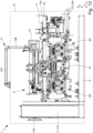
- FIG.1 shows in a very schematic view a processing system 1 according to the present invention.
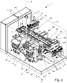
- Fig.2 the processing system 1 is shown in a perspective, simplified representation.
- the processing system 1 is designed in particular for the simultaneous processing of several spectacle lenses 2.
- the processing system 1 enables in particular a high throughput of spectacle lenses 2 with a small footprint, i.e. a small required installation area on the floor.
- the footprint or the required installation area of the processing system 1 is preferably at most 20 m 2 , preferably at most 10 m 2 , in particular about 2 mx 3.2 m.
- the processing system 1 is designed to (completely) process more than 60 spectacle lenses 2, in particular approximately 80 or more spectacle lenses 2 per hour.
- a focus of the processing system 1 is in particular on the shortest possible downtimes or idle times of individual processing stations, a high utilization of individual processing stations and/or the shortest possible dwell time of the spectacle lenses 2 in the processing system 1.
- the processing system 1 is designed for milling, turning, marking, polishing and/or cleaning, washing and/or drying, and optionally for measuring, edging and/or coating of spectacle lenses 2.
- the milling, turning and polishing refers to the processing of a flat side or optical surface of a spectacle lens 2.
- the flat side preferably forms an optical surface or optically effective surface of the spectacle lens 2 and is usually not flat, but slightly curved, for example spherical or toric, as in particular also in Fig.3 is indicated.
- the processing system 1 is preferably designed for processing blocked spectacle lenses 2 or spectacle lenses 2 that are attached to a block piece 2A. However, this is not mandatory; the processing system 1 can also be designed for blockless processing of spectacle lenses 2.
- Fig.3 shows in a schematic section a spectacle lens 2 which is blocked, i.e. temporarily attached, to an associated block piece 2A by means of a block material 2B.
- a protective layer 2C can be provided between the block material 2B and the spectacle lens 2, which can be provided, for example, by a coating such as a lacquer or Film or the like or by a foil (for example glued on).
- the block piece 2A is designed in particular for clamping with a defined rotational position for machining the associated spectacle lens 2.
- the spectacle lens 2 preferably has a "block side” and a “processing side".
- the block side i.e. the side or flat side of the spectacle lens 2 to which the block piece 2A is attached or which faces the block piece 2A, is already completely processed and/or only the (still unprocessed) processing side is processed.
- the block piece 2A facilitates the handling and alignment of the spectacle lens 2.
- the block piece 2A is not explicitly discussed below.
- the term "spectacle lens 2" also includes spectacle lenses 2 with block pieces 2A arranged thereon.
- the processing system 1 preferably has a system for detecting the position of the spectacle lenses 2 and/or for aligning the spectacle lenses 2. This can be done, for example, by one or more measuring devices for determining the position and/or alignment devices for aligning the spectacle lenses 2 in a specific position and/or for maintaining a specific position of the spectacle lenses 2.
- such devices can be assigned to one or more handling devices and/or one or more processing stations of the processing system 1.
- the X, Y and Z axes are preferably orthogonal to each other.
- the X and Y axes preferably run horizontally.
- the Z axis preferably runs vertically or perpendicularly.
- the X, Y and Z directions are referred to as directions that run parallel to the X, Y and Z axes.
- the X direction or X axis preferably runs in the central, longitudinal or main axis of the processing system 1 or parallel to it.
- the processing system 1 has a plurality of processing stations 3.
- the processing system 1 has at least two different processing stations 3 or at least two processing stations 3 for carrying out different processing operations.
- the processing system 1 preferably has a milling station 3A, a turning station 3B, a marking station 3C, a polishing station 3D and/or a cleaning station 3E.
- the stations 3A-E each represent a processing station 3.
- a processing station 3 in particular the milling station 3A, turning station 3B and/or polishing station 3D, preferably has a tool for processing the spectacle lens 2, a workpiece spindle or spindle for the spectacle lens 2 to be processed and/or a tool spindle for the processing tool.
- the workpiece spindle has a chuck 2D for the spectacle lens 2 or the block piece 2A, as in Fig. 17 shown by way of example.
- a processing station 3 preferably has a work space for processing spectacle lenses 2, in particular wherein the workpiece spindle and/or tool spindle are arranged in the work space. Different processing stations 3 preferably have different workpiece spindles, tool spindles and/or work spaces.
- the rotary station 3B is preferably decoupled from vibrations, for example by means of air bearings.
- vibrations for example by means of air bearings.
- other solutions are also possible here.
- the processing system 1 is designed to carry out a complete processing or surface processing, also referred to as surfacing, of the spectacle lenses 2.
- a surface processing is in particular a processing of the optical surface(s) or flat side(s) of a spectacle lens 2.
- a "complete processing" in the sense of the present invention includes in particular milling, turning, polishing and/or cleaning and optionally marking.
- a complete processing can optionally also include coating and/or edge processing.
- Other solutions are possible, in particular incomplete or only partial processing in the processing system 1.
- processing stations 3 that carry out the same type of processing for example polishing the spectacle lenses 2 are referred to as “similar” processing stations 3.
- processing stations 3 that carry out different types of processing are referred to as “different” processing stations 3.
- the milling station 3A, turning station 3B, marking station 3C, polishing station 3D and cleaning station 3E are each different types of processing stations 3.
- the processing system 1 can also have a plurality of similar processing stations 3.
- the processing system 1 preferably has exactly two polishing stations 3D.
- the spectacle lens 2 is processed in all different processing stations 3 for different processing operations.
- the (different) processing operations in the different processing stations preferably build on one another or preferably form a subsequent processing of the spectacle lens 2.
- the processing sequence is the same for each spectacle lens 2.
- the spectacle lens 2 is preferably processed in only one of the similar processing stations 3.
- the processing system 1 preferably has a transport system 4 for transporting the spectacle lenses 2 within the processing system 1.
- the spectacle lenses 2 are preferably transported in transport containers 5 which are transported by means of the transport system 4.
- the transport containers 5 and/or spectacle lenses 2 are preferably transported in the X direction (by means of the transport system 4).
- the transport system 4 preferably has several, in particular separate, transport devices 4A, in the example shown two transport devices 4A.
- the transport devices 4A can also be formed by different sections of a common transport system 4, for example forming a continuous conveyor track.
- transport devices 4A preferably also apply to transport sections.
- the transport sections or trans-devices 4A preferably run at least partially, piece by piece or largely in a straight line.
- the transport devices 4A are preferably designed as a roller conveyor or conveyor belt.
- the transport devices 4A are preferably arranged parallel to the X-axis and/or to each other or run in the X-direction.
- the transport system 4 or the transport devices 4A preferably serve to transport the transport containers 5 or spectacle lenses 2 along or past the processing stations 3.
- the processing system 1 has one or more handling devices 6, 7, 8, 18 for handling the spectacle lenses 2 and/or for handling tools 15 for processing the spectacle lenses 2.
- the term "handling" of a spectacle lens 2 is understood to mean in particular one or more of the following steps: removal of the spectacle lens 2 from a transport container 5, transfer of the spectacle lens 2 from the transport container 5 to one or more processing stations 3, transfer of the spectacle lens 2 to the processing station 3, in particular insertion into a spectacle lens holder or a chuck 2D of the processing station 3, removal of the spectacle lens 2 from a processing station 3, in particular immediate removal of the spectacle lens 2 from a spectacle lens holder or a chuck 2D of the processing station 3, transfer of the spectacle lens 2 between two processing stations 3 or transfer of the spectacle lens 2 from one processing station 3 to another processing station 3 or between two processing stations 3 and/or transfer of the spectacle lens 2 to a transport container 5 or placing the spectacle lens 2 in a transport container 5.
- the handling of a spectacle lens 2 can involve changing a relative position of the spectacle lens 2, for example a Rotating, tilting, pivoting and/or otherwise aligning the lens 2.
- the handling devices 6-8 are in Fig.2 omitted for the sake of clarity and are shown in detail in further figures.
- the handling devices 6-8 are preferably designed for handling spectacle lenses 2 and/or tools 15 independently of the processing in the processing stations 3 and/or independently of the transport of the transport containers 5 by means of the transport system 4.
- the various handling devices 6-8 are preferably independent of one another and/or do not have any common axes of movement.
- individual, several or all handling devices 6-8 are assigned to several processing stations 3.
- the handling devices 6-8 are preferably designed either for handling spectacle lenses 2 or for handling tools 15. However, it is also possible that one or more of the handling devices 6-8 is or are designed both for handling spectacle lenses 2 and for handling tools 15.
- the handling devices 6-8 work independently of one another and/or independently of processing of the spectacle lenses 2 in the processing stations 3.
- spectacle lenses 2 and/or tools 15 are handled by means of one or more of the handling devices 6-8, in particular moved or transferred between different positions, while a spectacle lens 2 is being processed in a processing station 3 (assigned to the handling device 6-8).
- idle times of the processing stations 3, i.e. periods in which no processing of a spectacle lens 2 takes place in a processing station 3 can be minimized. This increases the throughput of the processing stations 3 or of the processing system 1.
- the handling devices 6-8 are preferably positioned as close as possible to the transport system 4 and/or the respectively assigned processing stations 3.
- handling devices 6-8, 18 are designed to detect transport containers 5 or spectacle lenses 2 and/or to determine or detect the position of these, for example by means of a detection device 4E described later and/or one or more other or further position detection devices.
- the processing system 1 preferably has a base frame 9 which supports the processing stations 3 and/or the transport system 4 or on which the processing stations 3 and/or the transport system 4 are arranged.
- the base frame 9 preferably comprises a metal frame or is formed thereby.
- the processing system 1 preferably has a housing or a casing 10.
- the processing stations 3 and/or the transport system 4 are preferably arranged within the casing 10 or surrounded by the casing 10.
- the casing 10 forms an outer casing or boundary of the processing system 1.
- the panel 10 can be attached to the base frame 9 or connected to it. However, it is also possible for the panel 10 to be separated from the base frame 9, for example by anchoring it in the ground without contact with the base frame 9.
- Fig.4 and 8th Different embodiments of the casing 10 are indicated. In particular, it is possible that parts of the processing system 1 are arranged outside the casing 10. In the Fig.8 In the example shown, the control cabinet 11A is arranged outside the casing 10.
- the casing 10 preferably has several accesses, such as openings, flaps, doors, windows and/or other devices, which allow access to the space surrounded or delimited by the casing 10.
- accesses such as openings, flaps, doors, windows and/or other devices, which allow access to the space surrounded or delimited by the casing 10.
- access to individual processing stations 3, to the transport system 4 and/or to the control cabinet 11A is possible, for example for inspection, maintenance, servicing and/or repair.
- the accesses can preferably be opened and/or closed.
- the transport system 4 can be arranged in the vicinity of the casing 10 in such a way that direct access to the transport system 4 is possible through accesses to the casing, e.g. if the transport system 4 is arranged on the outer edge of the processing system 1 or at least partially in the vicinity of the casing and/or has only one transport device 4A.
- the processing system 1 preferably has an integrated or common control for the processing stations 3, the transport system 4 and/or the handling devices 6-8.
- the control is preferably arranged or housed in one or more control cabinets 11A.
- the control or the control cabinet 11A is preferably arranged on a front side of the processing system 1, the transport system 4 and/or the casing 10 and/or on a transverse side of the base frame 9 or on or at the base frame 9.
- the control cabinet 11A can be movable so that access to the processing system 1 or parts thereof, such as the transport system 4 and/or one or more processing stations 3, is enabled or facilitated, for example by moving, rotating, folding or pivoting the control cabinet 11A.
- the control system can have one or more separate or independently operating control devices 11 for controlling one or more components of the processing system 1 or can be formed by this. This will be discussed in more detail later.
- the processing system 1 preferably has an operating device 12.
- the operating device 12 preferably has a display device 12A and/or an input device 12B.
- the display device 12A and input device 12B can in particular also be formed by the same element, for example a touch screen or a touch-sensitive display.
- processing stations 3 of the processing system 1 can be controlled or operated individually or independently of one another. This will be discussed in more detail later.
- the operating device 12 is arranged on an arm 13, in particular at its end.
- the processing system 1 or the arm 13 is preferably designed such that the operating device 12 can be used flexibly or can be positioned around the processing system 1 or optionally on different sides or in front of different processing stations 3. This will be discussed in more detail later.
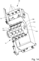
- the processing system 1 preferably has a tool magazine 14.
- the tool magazine 14 can be assigned to one or more processing stations 3 or can have or store tools 15 for one or more processing stations 3.
- the tool magazine 14 is assigned to one or two polishing stations 3D and/or arranged between two polishing stations 3D.
- the tools 15 are in particular polishing tools or polishing heads.
- the machining system 1 can also have one or more tool magazines 14 for other tools 15, for example milling and/or turning tools.
- the cleaning station 3E is assigned to one or more polishing stations 3D and/or designed to clean spectacle lenses 2 and/or tools 15, in particular polishing tools.
- the cleaning station 3E is preferably arranged next to one or more polishing stations 3D, in particular between two polishing stations 3D.
- the cleaning station 3E is preferably designed for washing and/or drying spectacle lenses 2 and/or tools 15. This will be discussed in more detail later.
- the tool magazine 14 and the cleaning station 3E form a common structural unit or the tool magazine 14 is integrated into the cleaning station 3E.
- the processing system 1 preferably has a supply system 20 for supplying one or more processing stations 3 with operating resources.
- the arrangement or position of the supply system 20 is shown in Fig.1 indicated schematically.
- the supply system 20 is not shown in the other figures.
- the supply system 20 is preferably arranged near the input E and/or output A, near the polishing station 3D, on the polishing side 1B and/or on the side of the processing system 1 opposite the control cabinet 11A.
- the supply system 20 is arranged laterally offset from the transport system 4 and/or at least partially below the transport system 4.
- the supply system 20 has in particular storage containers for various operating materials of the processing stations 3, in particular the polishing stations 3D, for example coolant, polishing agent, cleaning fluid or the like.
- the supply system 20 preferably has one or more lines 20A for supplying operating resources to the processing stations 3 and/or for removing (used or consumed) operating resources or waste, waste water or the like from the processing stations 3. Accordingly, the supply system 20 can also have collecting containers for operating resources, waste, waste water or the like removed from the processing stations.
- the transport system 4 or the processing system 1 is preferably connected to an external transfer system 16 or a transfer system 16 that is separate from the processing system 1, via which the spectacle lenses 2 or transport containers 5 with the spectacle lenses 2 are or can be conveyed to the processing system 1 or transport system 4 and/or are or can be conveyed away from the processing system 1.
- the base frame 9 preferably has several, in particular two, sub-frames 9A, each of which has a base frame for one or more processing stations 3 and in particular form a transport device 4A.
- the sub-frames 9A can preferably be connected to one another to form the base frame 9 or fastened to one another.
- the sub-frames 9A can be connected to one another on site, i.e. at the installation location of the processing system 1, to form the base frame 9 easily or with little effort and/or in a short time.
- the processing system 1 is divisible into two parts 1A, 1B or is composed or can be composed of two parts 1A, 1B.
- each of the two parts 1A, 1B can function separately and/or independently of the other part 1A, 1B.
- the parts 1A, 1B are then each designed in such a way that they form an independently functional processing system 1 for the same or different processing operations.
- the processing system 1 is divided into two parts 1A, 1B, preferably a processing side 1A and a polishing side 1B.
- the two sides or parts 1A, 1B of the processing system 1 each form a fully assembled structural unit with a transport device 4A, one or more processing stations 3, one or more handling devices 6-8 and/or a control or a control cabinet 11A.
- the processing side 1A has the milling station 3A and the turning station 3B and optionally the marking station 3C.
- the marking station 3C can, however, also be integrated into the polishing side 1B.
- the polishing side 1B has two preferably identically designed polishing stations 3D.
- the polishing side 1B preferably has the tool magazine 14 and/or the cleaning station 3E.
- the processing side 1A can form a processing system 1 for milling, turning and/or marking spectacle lenses 2.
- the polishing side 1B can form a processing system 1 for polishing, cleaning and/or marking spectacle lenses 2.
- the processing system 1 is designed to carry out a method according to claim 12.
- the method is described below primarily with reference to a single spectacle lens 2.
- several spectacle lenses 2 are processed simultaneously in different processing stations 3.
- different spectacle lenses 2 pass through the same processing stations 3 and/or all spectacle lenses 2 pass through the processing stations 3 in the same order.
- the steps explained below are intended to provide an overview of the method.
- the method can in particular comprise further steps which are described later.
- the processing system 1 is in particular also designed to carry out these further steps.
- the spectacle lens 2 is first transferred or conveyed to the processing system 1 or transport system 4, in particular by means of the external transfer system 16 and/or in transport containers 5.
- spectacle lenses 2 are processed and/or transported and/or handled simultaneously.
- the spectacle lens 2 is preferably processed in succession in several, in particular different, processing stations 3.
- the transport container 5 assigned to the spectacle lens 2 is transported in parallel or simultaneously by the transport system 4 and the spectacle lens 2 is handled by one or more handling devices 6, 7.
- the spectacle lens 2 is preferably first processed or milled in the milling station 3A.
- the transport container 5 with the spectacle lens 2 is preferably transported in front of the milling station 3A by means of the transport system 4 and the spectacle lens 2 is removed from the transport container 5 by means of the handling device 6 and transferred to the milling station 3A.
- the spectacle lens 2 is removed from the milling station 3A according to the invention using the same handling device 6 and transferred to a further processing station 3, in particular to the turning station 3B.
- the spectacle lens 2 is then preferably subjected to rotary processing in the turning station 3B.
- the spectacle lens 2 is removed from the turning station 3B, preferably using the same handling device 6.
- the spectacle lens 2 is not returned to the transport system 4 or placed in the transport container 5 between milling and turning.
- the spectacle lens 2 is preferably placed again, in particular by means of the same handling device 6, in a transport container 5, particularly preferably in the same transport container 5 from which it was previously removed.
- the transport container 5 was preferably transported further in the meantime or transported from the milling station 3A to or in front of the turning station 3B.
- the further transport preferably takes place during the processing of the spectacle lens 2 and/or the handling of the spectacle lens 2 by means of the handling device 6.
- the handling device 6 removes another spectacle lens 2 from the same or another transport container 5 during the processing of a first spectacle lens 2 in the milling station 3A and preferably already holds or stores it for subsequent processing in the milling station 3A.
- the handling device 6 can then remove this spectacle lens 2 from the milling station 3A and immediately afterwards transfer the stored, not yet milled, additional spectacle lens 2 to the processing station 3 or milling station 3A.
- the first fully milled spectacle lens 2 is then transferred to the turning station 3B as described. It is also possible that after the first spectacle lens 2 has been milled, it is first transferred to the turning station 3B and only then is the other spectacle lens 2 (already in stock) transferred to the milling station 3A.
- a spectacle lens 2 is already being processed in the turning station 3B, it is preferable to wait until the processing is finished in order to first remove the spectacle lens 2 from the turning station 3B and only then to transfer the next spectacle lens 2 to the turning station 3B.
- Turning and/or milling is preferably carried out as in the EN 10 2005 057 725 A1 described.
- a spectacle lens holder or workpiece spindle of the milling station 3A and/or turning station 3B is aligned horizontally and/or the spectacle lens 2 is rotated about a horizontally running axis of rotation during turning or milling.
- the spectacle lens 2 is marked or signed after milling and/or turning.
- the marking or signing can also be done at a later point in time, in particular after polishing the spectacle lens 2.
- the transport container 5 with the lens 2 is preferably transported further, in particular to the signing station 3C.
- the spectacle lens 2 is removed from the transport container 5 by means of a handling device 18 of the signing station 3C, then signed or marked, in particular with a laser 21 or laser beam, and transferred back to the transport container 5 or deposited in it.
- the transport container 5 with the spectacle lens 2 is then transported further and/or transferred from the processing side 1A to the polishing side 1B.
- the transport container 5 is transferred to a further or the second transport device 4A of the transport system 4, preferably with a changing device 4B arranged in particular at the end of the transport system 4 or the first transport device 4A.
- the further or next processing step is polishing the spectacle lens 2.
- the processing system 1 preferably has two polishing stations 3D, in particular of the same type or of identical design. This can increase the throughput of the processing system 1, since the Polishing process usually takes significantly longer than turning and/or milling the lens 2.
- the processing system 1 preferably has a further handling device 7 for handling spectacle lenses 2, which is separate and/or operates independently of the aforementioned handling device 6.
- the handling device 7 is preferably assigned to several processing stations 3, in particular the two polishing stations 3D.
- the handling device 7 preferably removes the spectacle lens 2 from the transport container 5 and transfers it to one of the polishing stations 3D.
- the spectacle lens 2 is preferably processed or polished in only one of the two polishing stations 3D.
- the polishing station 13D or each of the polishing stations 13D is designed for the simultaneous or parallel polishing of two spectacle lenses 2.
- the handling device 7 is preferably designed for handling two spectacle lenses 2 simultaneously or in pairs.
- two spectacle lenses 2 are removed from the transport container 5 simultaneously or in pairs and/or transferred to the polishing station 3D.
- two spectacle lenses 2 are removed from the polishing station 3D simultaneously or in pairs and/or transferred to the transport container 5.
- two spectacle lenses 2 to be polished are simultaneously removed from the transport container 5, then two already polished spectacle lenses 2 are removed from the polishing station 3D and immediately thereafter the two spectacle lenses 2 still to be polished are transferred to the polishing station 3D and only then are the two already polished spectacle lenses 2 placed back in one or the original transport container 5.
- the handling device 7 preferably moves, in particular parallel to the transport system 4, while processing of spectacle lenses 2 takes place in a polishing station 3D.
- spectacle lenses 2 are transferred to and/or removed from one of the polishing stations 3D, while further spectacle lenses 2 are polished in the other polishing station 3D.
- the polishing tools are changed at the same time as the spectacle lenses 2 are transferred and/or removed or changed in the polishing station 3D.
- the handling device 8 is preferably provided for changing the polishing tools.
- polishing is carried out as in the US 2014/0038494 A1 described or the 3D polishing station is designed as described in this document.
- the spectacle lenses 2 are preferably cleaned, in particular washed and/or dried. This takes place in particular while further spectacle lenses 2 are being polished in the polishing station 3D or the polishing stations 3D.
- the previously described signing of the spectacle lenses 2 can also be carried out after the spectacle lenses 2 have been polished and/or cleaned.
- the transport containers 5 or spectacle lenses 2 are finally handed back to the external transfer system 16.
- the processing system 1 preferably several spectacle lenses 2 are processed simultaneously in different processing stations 3, in particular milled, machined by turning, signed and preferably polished in one of several polishing stations 3D.
- the transport containers 5 are preferably transported by the transport system 4, while the spectacle lenses 2 are handled by means of several handling devices 6, 7, 18 and/or processed in the processing stations 3.
- the transport system 4 is arranged at least substantially in the center or central axis of the processing system 1 and/or the processing stations 3 or at least parts thereof are arranged on different, in particular mutually opposite, sides of the transport system 4.
- the transport devices 4A are preferably arranged directly adjacent to one another, in particular next to one another.
- the processing stations 3 preferably form two rows, in particular with the transport system 4 and in particular the two transport devices 4A being arranged between the rows. According to another embodiment, however, it can also be provided that the processing stations 3 are arranged between the transport devices 4A and/or the transport devices 4A are each arranged at the edge of the processing system 1.
- each of the parts 1A, 1B has a transport device 4A.
- the processing stations 3 are preferably arranged at least partially laterally and/or below the transport system 4.
- the transport devices 4A are at least substantially similar or identical. Statements relating to one of the transport devices 4A preferably also apply to the other transport device 4A.
- the transport devices 4A can also be formed merely by different sections of a transport system 4.
- the transport devices 4A are preferably designed as linear conveyors, particularly preferably as conveyor belts, and/or arranged parallel to one another.
- the transport system 4 or the transport devices 4 can be clocked.
- the transport devices 4A preferably have opposite or anti-parallel transport directions R1, R2.
- the transport directions R1 and/or R2 preferably run parallel to the X-axis and/or horizontally.
- one or more transport devices 4A may have multiple transport directions or to be designed to transport transport containers 5 or spectacle lenses 2 in opposite directions or back and forth.
- the transport containers 5 are preferably designed as boxes.
- the box is open on the top so that the spectacle lenses 2 can be handled from above.
- each transport container 5 is assigned to a spectacle lens 2 or a pair of spectacle lenses 2 or vice versa.
- the spectacle lenses 2 are preferably placed back in the same transport container 5 from which they were previously removed for processing.
- the transport containers 5 have an identifier for the transport container 5 or the spectacle lenses 2 transported with the transport container 5.
- the identifier can be designed, for example, as a barcode or RFID chip.
- the lenses 2 and/or block pieces 2A can each be provided with an identifier.
- information about the spectacle lenses 2 or about the processing of the spectacle lenses 2 can be retrieved via the identifier and/or the identifier contains such information.
- the processing system 1 or transport system 4 preferably has one or more reading devices or detection devices 4E for detecting, in particular reading, the identifiers, in particular of the transport containers 5.
- the detection devices 4E are preferably arranged laterally on the transport devices 4A, in particular on the side of a transport belt or conveyor belt.
- one or more of the handling devices 6, 7, 18 have a detection device 4E.
- the handling device 7 for spectacle lenses 2 of the polishing side 1B has a detection device 4E.
- the processing system 1 or transport system 4 preferably has a receiving and a delivery point or an input E and an output A for spectacle lenses 2 or transport containers 5.
- input refers in particular to the point at which the spectacle lenses 2 or transport containers 5 enter the processing system 1 or are transferred (from the external transfer system 16) to the processing system 1. Accordingly, the term “output” refers to the point at which the spectacle lenses 2 or transport container 5 can leave the processing system 1 or transport system 4 again and/or be transferred to the external transfer system 16.
- the input E and output A of the processing system 1 or transport system 4 are preferably arranged directly adjacent to one another or next to one another and/or on the same side of the processing system 1.
- the processing system 1 or transport system has a plate 10A which is arranged at the entrance E and/or exit A or forms the entrance E and/or exit A.
- the plate 10A has two openings through which the spectacle lenses 2 or transport containers 5 enter or leave the processing system 1 or transport system 4.
- the plate 10A can in particular form part of the cladding 10. However, it is also possible for the plate 10A to be arranged within the cladding 10.
- the transport system 4 is designed such that the transport containers 5 or spectacle lenses 2 enter and leave the processing system 1 on the same side or do not pass completely through the processing system 1 in one direction or along one axis.
- the transport system 4 preferably has a changing device 4B, by means of which the spectacle lenses 2 or transport containers 5 can change between transport devices 4A or can change or be transported from one transport device 4A to another transport device 4A.
- the changing device 4B is preferably arranged in an end region of the transport system 4 or the transport devices 4A and/or adjacent to or shortly before the control cabinets 11A.
- the changing device 4B is arranged in particular at the end of the transport system 4 or the transport device 4A and/or opposite the entrance E and/or exit A.
- the changing device 4B has a transport direction R3 or the transport containers 5 are conveyed in the transport direction R3 by means of the changing direction 4B.
- the transport direction R3 preferably runs transversely, in particular perpendicularly, to the first and/or second transport direction R1, R2.
- the transport direction R3 runs in the Y direction.
- the changing device 4B is preferably designed for the transverse transport of the transport containers 5 or spectacle lenses 2.
- the changing device 4B can also be designed to rotate the transport containers 5.
- the changing device 4B can, for example, have two curved elements, so that a U-shaped transport system 4 is formed by the transport devices 4A and the changing device 4B.
- the changing device 4B can alternatively or additionally be designed to rotate the transport containers 5 on the spot or to rotate them about a rotation axis.
- the changing device 4B can also be formed by or have a robot arm or the like, wherein the robot arm is designed to grip a transport container 5 and/or spectacle lenses 2 and to transfer them from one transport device 4A to the other transport device 4A. If necessary, the transport container 5 can also be rotated.
- the spectacle lenses 2 or transport containers 5 are first transferred to the first transport device 4A at the entrance E, transported within the processing system 1 in the first transport direction R1, preferably in a straight line or linear manner, transferred to the other or second transport device 4A by means of the changing device 4B, transported by means of the further transport device 4A in the second transport direction R2 opposite to the first transport direction R1 and finally transferred again to the external transfer system 16 or another device, preferably at the exit A.
- one or more further changing devices 4B can also be provided, in particular in the area of the entrance E and/or exit A and/or on the side of the transport system 4 opposite the first changing device 4B, but also at any other positions.
- the transport system 4 can also have more than two or one or more further transport devices 4A, in particular to facilitate circulation of spectacle lenses 2 or transport containers 5 and/or overtaking of spectacle lenses 2 or transport containers 5.
- the further transport device 4A or the further transport devices 4A is or are preferably arranged parallel to the transport devices 4A shown in the figures and/or has or have transport directions parallel to the transport directions R1 and/or R2.
- the further transport devices 4A are preferably arranged immediately adjacent to the transport devices 4A shown in the figures, for example above, below, next to and/or in between.
- the transport devices 4A form a circuit for the spectacle lenses 2 or transport containers 5.
- the transport system 4 or the further transport devices 4A can in particular have one or more (additional) changing devices 4B.
- the transport containers 5 or spectacle lenses 2 can be stopped as required by means of the further transport device 4A and/or moved or transported forwards and/or backwards, in particular along and/or against the transport direction R1 and/or R2.
- the same (further) transport device 4A is designed to stop and/or move or transport the transport containers 5 or spectacle lenses 2 in two opposite directions.
- connections or (changeover) devices can be provided for connecting the further transport device(s) 4A, so that at different positions transport containers 5 or spectacle lenses 2 can change between the further transport device 4A and a transport device 4A that transports the spectacle lenses 2 along the processing stations 3 and/or overtaking of spectacle lenses 2 or transport containers 5 is possible.
- Overtaking of spectacle lenses 2 or transport containers 5 can alternatively or additionally be made possible or implemented via a storage or waiting area for the transport containers 5.
- the waiting area can have or be formed by a (stationary) transport device 4A, in particular a stationary conveyor belt, or another device that is suitable for temporarily receiving or temporarily keeping a transport container 5 ready, such as a shelf or the like.
- the storage or waiting area is preferably arranged between the transport devices 4A.
- the storage or waiting area is preferably connected to the transport devices 4A via a changing device 4B, so that the transport containers 5 can be can be switched or transferred between the parking or waiting area and the transport devices 4A.
- the additional transport device(s) 4A and/or the waiting area make it possible for transport containers 5 or spectacle lenses 2 to be conveyed past one or more processing stations 3, i.e. to skip individual processing stations 3, and/or for spectacle lenses 2 not to be processed in all processing stations 3 or only in selected processing stations 3.
- the transport system 4 is provided or designed only for transporting the transport containers 5.
- the handling of the spectacle lenses 2 themselves, in particular the transfer of the spectacle lenses 2 to the processing stations 3 and the removal of the spectacle lenses 2 from the processing stations 3, is preferably carried out by means of the handling devices 6, 7, 18.
- the handling devices 6, 7, 18 preferably operate independently of the transport system 4 and/or are controlled separately.
- the spectacle lenses 2 are preferably removed from the transport system 4 or transport container 5 by means of one of the handling devices 6, 7, 18 and/or, after processing, are placed back in the same transport container 5 or transferred to the transport system 4 or the transport container 5.
- the transport container 5 is transported further by means of the transport system 4, while spectacle lenses 2 removed from the transport container 5 are processed in one or more processing stations 3 and/or handled by means of the handling device 6, 7.
- the transport system 4 preferably has one or more stoppers 4C.
- the stopper 4C is preferably designed to stop or halt transport containers 5 or to (temporarily) prevent further transport of transport containers 5.
- the stopper 4C is formed by a plate or a slider which can be moved perpendicular to the transport device 4A or the conveyor belt, in particular in the Z direction.
- the stopper 4C is preferably assigned to a processing station 3 and/or positioned near or in front of the processing station 3 in such a way that the spectacle lens 2 can be removed from the transport container 5 by means of the handling device 6, 7, 18 and/or transferred to the processing station 3.
- a stopper 4C can be arranged (additionally) at the entrance E and/or at the exit A and/or the stopper 4C can be assigned to different transport directions. This is particularly advantageous if the transport device 4A to which the stopper 4C is assigned is designed to transport transport containers 5 or spectacle lenses 2 in opposite directions or back and forth.
- the processing system 1 or transport system 4 preferably has one or more storage devices 4D for storing transport containers 5 or spectacle lenses 2.
- the storage device 4D is preferably designed for temporarily receiving or temporarily storing one or more transport containers 5.
- the transport containers 5 can be stacked in the storage device 4D or arranged vertically or in the Z direction one above the other.
- the storage device 4D is preferably arranged near the entrance E and/or exit A of the transport system 4.
- the storage device 4D is preferably arranged at an end of the transport system 4 opposite the changing device 4B.
- each of the transport devices 4A has a storage device 4D, in particular in the vicinity of the entrance E and/or exit A.
- the transport device 4A can have a plurality of storage devices 4D, for example in the vicinity of the changing device 4B and/or (in each case) between two processing stations 3.
- the external transfer system 16 is preferably formed by one or more conveyor belts.
- the conveying direction of the transfer system 16 or the conveyor belt preferably runs in the Y direction and/or transversely, in particular perpendicularly, to the transport devices 4A or the transport directions R1, R2.
- the transfer system 16 is indicated as a continuous conveyor belt, from which two sections branch off transversely and connect the transfer system 16 to the transport system 4 or its inlet and outlet E, A.
- the transport containers 5 are preferably conveyed transversely to the inlet E and/or from the outlet A.
- the processing system 1 or the transport system 1 is preferably arranged transversely, in particular perpendicularly, to the transfer system 16 or a main conveying direction H of the transfer system 16.
- the transport direction R1, R2 runs transversely, in particular perpendicularly, to the main conveying direction H of the transfer system 16.
- the orientation of the transport containers 5 with respect to the transfer system 16 or the main conveying direction H can be maintained or changed during the transition between the transfer system 16 and the transport system 4.
- the transfer system 16 or processing system 1 has curve elements at the entrance E and exit A, via which sections of the transfer system 16 running transversely or at right angles to the main conveying direction H are connected to a conveyor belt of the transfer system 16 that conveys the transport containers 5 in the main conveying direction H.
- the transport containers 5 are conveyed in a curve before the entrance E and also in a curve after the exit A, so that the transport system 4 and the transfer system 16 form a continuous conveyor belt with several bends or curves.
- the orientation of the transport containers 5 with respect to the main conveying direction H changes at the transition between the transfer system 16 and the transport system 4.
- transport containers 5 are retained. This can also be achieved by rotating the transport containers 5 before entering the processing system 1 or after leaving the processing system 1, without providing cam elements.
- the processing system 1 or transport system 4 and/or the handling devices 6, 7, 18 preferably have a sensor 4F with which it can be determined whether one or more spectacle lenses 2 are located in a transport container 5.
- the sensor 4F is particularly preferably designed as a button.
- the sensor 4F is arranged on the side of the transport device 4A in such a way that a sensor of the sensor 4F can be moved vertically or in the Z direction and/or is arranged above the transport containers 5 or spectacle lenses 2 transported by the transport device 4.
- a sensor of the sensor 4F can be moved vertically or in the Z direction and/or is arranged above the transport containers 5 or spectacle lenses 2 transported by the transport device 4.
- it can be determined whether there are one or two spectacle lenses 2 in a transport container 5.
- the senor 4F has several, in particular two, sensors arranged next to one another.
- the processing system 1 or transport system 4 and/or the handling devices 6, 7, 18 can have several sensors 4F.
- one sensor 4F can be assigned to several or all processing stations 3.
- the transport system 4 or the transport device 4A can be designed to be exchangeable and/or modular or form a module or an exchangeable structural unit.
- the transport system 4 or the transport device 4A is preferably designed in such a way that it can be moved out of the processing system 1 at least substantially completely or as a unit and/or can be exchanged. This is particularly advantageous in order to facilitate repair, maintenance, inspection, servicing and/or access to to enable or facilitate the transport device 4A or the transport system 4.
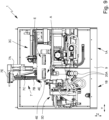
- Fig.1 While the handling devices 6-8, 18 are shown in Fig.1 are only indicated very schematically and in Fig.2 were omitted, is in Fig.4 and 5 the processing system 1 with the handling device 6 is shown in different views.
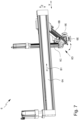
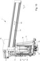
- Fig.6 and 7 show the handling device 6 in different views.
- the handling device 6 is designed for handling spectacle lenses 2, in particular for the simultaneous handling of several spectacle lenses 2, particularly preferably two spectacle lenses 2.
- the handling device 6 is assigned to several processing stations 3, in particular the milling station 3A and the turning station 3B, and/or arranged on the processing side 1A.
- the handling device 6 is designed to transfer spectacle lenses 2 between the transport system 4 and several processing stations 3.
- the handling device 6 is designed to directly transfer spectacle lenses 2 to a workpiece spindle or a chuck 2D of the workpiece spindle of the milling station 3A and/or the turning station 3B.
- the handling device 6 can be moved along or parallel to the transport system 4 and/or parallel to the X-axis.
- the handling device 6 is preferably arranged at least partially above the transport system 4 and/or designed to handle the spectacle lenses 2 from above the transport system 4 or the transport devices 4A. This is conducive to a compact structure.
- the handling device 6 or at least parts thereof are preferably arranged vertically above the transport system 4 or the transport device 4A.
- the handling device 6 preferably has a plurality of movement axes B1, B2, B3 and/or is movable or displaceable along the movement axes B1-B3.
- the movement axis B1, the movement axis B2 and/or the movement axis B3 is a linear movement axis.
- the movement axis B1 preferably runs at least substantially horizontally and/or parallel to the X-axis.
- the movement axis B1 runs parallel to the transport device 4A or transport direction R1, R2.
- the movement axis B1 is preferably arranged vertically above or above the transport system 4.
- the movement axis B2 preferably runs transversely, in particular orthogonally, to the movement axis B1.
- the movement axis B2 preferably runs obliquely to the vertical or Z direction and/or at least partially above the transport system 4.
- the movement axis B3 preferably runs vertically or perpendicularly or in the Z direction.
- the handling device 6 preferably has a rail or guide 6A or is arranged on it.
- the handling device 6 can preferably be moved along the guide 6A or parallel to the guide 6A.
- the guide 6A is designed as a linear guide and/or arranged parallel to the transport device 4A or transport direction R1, R2 and/or X-axis.
- the guide 6A is preferably arranged above, in particular vertically or centrally above, the transport device 4A or the transport system 4.
- the guide 6A has the movement axis B1 or the guide 6A forms the movement axis B1.
- the guide 6A is also referred to as longitudinal guide 6A.
- the handling device 6 preferably has a guide 6B, hereinafter also referred to as transverse guide 6B for better differentiation.
- the longitudinal guide 6A and/or transverse guide 6B are preferably formed by a guide rail and/or a carriage or have these.
- the transverse guide 6B is preferably slidably mounted on the longitudinal guide 6A and/or movable or displaceable along the longitudinal guide 6A.
- the transverse guide 6B is preferably arranged transversely, in particular orthogonally, to the longitudinal guide 6A and/or movement axis B1.
- the transverse guide 6B is arranged at least partially above the transport system 4.
- the transverse guide 6B preferably runs obliquely to the vertical or Z-axis and/or perpendicular to the X-axis.
- the transverse guide 6B has the movement axis B2 or the transverse guide 6B forms the movement axis B2.
- the handling device 6 preferably has an adjusting device 6C.
- the adjusting device 6C is preferably movable or adjustable in the Z direction or along the movement axis B3.
- the adjusting device 6C forms the movement axis B3 or the adjusting device 6C has the movement axis B3.
- the adjusting device 6C is preferably displaceably mounted on the transverse guide 6B and/or movable or displaceable along the transverse guide 6B or movement axis B2.
- the handling device 6 preferably has a swivel head 6D.
- the adjusting device 6C has the swivel head 6D or the swivel head 6D is arranged on the adjusting device 6C, in particular at its lower end.
- the swivel head 6D is preferably pivotable about a pivot axis, as in Fig.7 indicated with an arrow.
- the swivel axis runs perpendicular to the movement axis B3 or Z-direction and/or in the Y-direction.
- the swivel head 6D is preferably pivotable by at least about 90°.
- the holding devices 6E are each designed as suction cups.
- the suction cups or holding devices 6E are preferably arranged at an angle of approximately 90° to one another. In particular, this supports a quick change of spectacle lenses 2.
- the handling device 6 or the swivel head 6D is preferably designed to hold two spectacle lenses 2 simultaneously.
- the following procedure is used to change spectacle lenses 2 or to exchange a processed spectacle lens 2 for a spectacle lens 2 to be processed in a processing station 3, in particular the milling station 3A and/or the turning station 3B.
- the swivel head 6D or one of the holding devices 6E is positioned over a transport container 5 with a second spectacle lens 2 to be processed and this second spectacle lens 2 is gripped by means of the holding device 6E and removed from the transport container 5. Then, preferably, the swivel head 6D with the second spectacle lens 2 to be processed is moved close to the processing station 3, in particular in such a way that the first spectacle lens 2 can be removed from the processing station 3 as quickly as possible using the swivel head 6D or the free holding device 6E when the processing is finished.
- the handling device 6 or the swivel head 6D is preferably moved or displaced to the completely machined spectacle lens 2 and the completely machined first spectacle lens 2 is gripped with the unoccupied holding device 6E and removed from the chuck 2D.
- the swivel head 6D is then preferably swiveled, preferably by approximately 90°, and if necessary the adjusting device 6C is moved before, during and/or after the swiveling of the swivel head 6D, so that the second spectacle lens 2 to be machined can be inserted into the processing station 3, in particular a chuck 2D of a workpiece spindle of the processing station 3.
- the second spectacle lens 2 is inserted into the processing station 3 or the chuck 2D.
- the swivel head 6D with the completely machined spectacle lens 2 is then preferably moved out of the processing station 3 again.
- the finished spectacle lens 2 is then transferred either to a further processing station 3, in particular the turning station 3B, or to the transport container 5 for the spectacle lens 2.
- the handling of spectacle lenses 2 with the handling device 6 preferably takes place during the processing of further spectacle lenses 2 in the processing stations 3, in particular the milling station 3A and/or the turning station 3B.
- one or more further spectacle lenses 2 are removed from transport containers 5, placed in transport containers 5 and/or transferred between the transport containers 5 and/or the processing stations 3.
- the processing times of the processing stations 3 can be used effectively and the throughput of spectacle lenses 2 can be increased or downtimes of the processing stations 3 can be minimized.
- the processing times for a spectacle lens 2 are usually around 10 to 15 seconds in the milling station 3A and around 30 seconds in the turning station 3B. It is therefore particularly advantageous for optimal utilization of the processing system 1 to quickly change the spectacle lenses 2, particularly at the turning station 3B, and/or to use the time in which one or more spectacle lenses 2 are being processed in the turning station 3B for further handling steps.
- Fig.8 and 9 the processing system 1 with the handling device 7 is shown in different views.
- Fig.10 and 11 show the handling device 7 in different representations.
- the handling device 7 is designed for handling spectacle lenses 2, in particular for the simultaneous handling of several spectacle lenses 2, particularly preferably four spectacle lenses 2 or two pairs of spectacle lenses 2.
- the handling device 7 is assigned to several processing stations 3, in particular one or more polishing stations 3D and/or the cleaning station 3E, and/or is arranged on the polishing side 1B.
- the handling device 7 is designed to transfer spectacle lenses 2 between the transport system 4 and several processing stations 3, in particular the polishing station 3D and/or cleaning station 3E.
- the handling device 7 is designed to directly transfer spectacle lenses 2 to one or more workpiece spindles or chucks 2D of the workpiece spindles of the polishing station 3D.
- the handling device 7 can be moved along or parallel to the transport system 4 or at least one of the transport devices 4A, in particular parallel to the X-axis.
- the handling device 7 of the polishing side 1B and the handling device 6 of the processing side 1A are arranged and/or movable parallel to one another.
- the handling device 7 is preferably arranged at least partially above the transport system 4 and/or designed to handle the spectacle lenses 2 from above the transport system 4 or the transport devices 4A. This is conducive to a compact structure.
- the handling device 7 or at least parts thereof are preferably arranged vertically above the transport system 4 or the transport device 4A. In particular, this is beneficial to a compact structure of the processing system 1.
- the handling device 7 preferably has several movement axes B4, B5, B6 and/or is movable or displaceable along the movement axes B4-B6.
- the movement axis B4 preferably runs at least substantially horizontally and/or parallel to the X-axis.
- the movement axis B4 is preferably arranged vertically above the transport system 4 or the transport device 4A.
- the movement axis B4 is preferably a linear movement axis.
- the movement axis B5 preferably runs vertically or perpendicularly or in the Z direction.
- the movement axis B5 is preferably a linear movement axis.
- the handling device 7 preferably has two, in particular parallel, movement axes B5.
- the movement axis B6 preferably runs vertically or perpendicularly or in the Z direction.
- the movement axis B6 is preferably a swivel or rotation axis.
- the handling device 7 has two, in particular parallel, axes of movement B6 or pivot axes or rotation axes.
- the handling device 7 preferably has a guide 7A or is arranged on it.
- the handling device 7 can preferably be moved along the guide 7A or parallel to the guide 7A.
- the guide 7A is designed as a linear guide and/or arranged parallel to the transport device 4A or transport direction R1, R2 and/or to the guide 6A of the handling device 6 of the processing side 1A.
- the guide 7A is preferably arranged above, in particular (vertically) above, the (polishing side) transport device 4A or the transport system 4.
- the guide 7A has the movement axis B4 or the guide 7A forms the movement axis B4.
- the guide 7A is also referred to as longitudinal guide 7A.
- the handling device 7 preferably has a rail or guide 7B, hereinafter also referred to as vertical guide 7B for better differentiation.
- the vertical guide 7B preferably runs vertically or in the Z direction.
- the vertical guide 7B has the movement axis B5 or the vertical guide 7B forms the movement axis B5.
- the longitudinal guide 7A and/or vertical guide 7B are preferably each formed by or comprise a guide rail and/or a carriage.
- the handling device 7 preferably has two vertical guides 7B, in particular of the same type or identical design.
- the vertical guides 7B are preferably arranged parallel to one another and/or next to one another.
- the handling device 7 preferably has an arm 7C.
- the arm 7C is preferably movably mounted on the vertical guide 7B and/or movable or displaceable along the vertical guide 7B.
- the arm 7C preferably protrudes from the vertical guide 7B at an angle to the movement axis B5.
- the handling device 7 preferably has two (at least predominantly) similar or identically designed arms 7C.
- the arms 7C are arranged in particular parallel to one another and/or next to one another.
- each of the arms 7C is mounted on a vertical guide 7B.
- the handling device 7 preferably has a carriage or carrier 7E for the arms 7C and/or vertical guides 7B.
- the arms 7C and/or vertical guides 7B are arranged or mounted on the common carrier 7E or held by it.
- the arms 7C are preferably movable or displaceable independently of one another.
- the arm 7C preferably has, in particular at the end or at the lower end, one or preferably several holding devices 7D for holding or gripping spectacle lenses 2.
- the various holding devices 7D of an arm 7C are predominantly identical, but preferably the holding devices 7D of the first arm 7C are designed differently than the holding devices 7D of the second arm 7C.
- the holding devices 7D of the first arm 7C are designed as suction cups and/or the holding devices 7D of the second arm 7C are designed as grippers with which the spectacle lenses 2 are held at the edge, in particular so that damage to the spectacle lens surfaces is avoided.
- the grippers of the second arm 7C have several fingers that are or can be placed on the edge of the spectacle lens 2 in order to hold it.
- the arm 7C with the holding devices 7D designed as suction cups is referred to as the first arm and the arm 7C with the holding devices 7D designed as grippers is referred to as the second arm.
- spectacle lenses 2 that still need to be processed or polished are gripped or held with the suction cups and/or that spectacle lenses 2 that have already been polished are gripped or held with the grippers.
- the guide 7B has the rotation axis or pivot axis or movement axis B6 or the two guides 7B each have a rotation axis or pivot axis or movement axis B6.
- the arm 7C can be rotated or pivoted about the vertical guide 7B or movement axis B6.
- the holding device 7D or the spectacle lens 2 held thereby can be moved from a position above the transport system 4 or transport container 5 to a position above the polishing station 3D, in particular a workpiece spindle of the polishing station 3D.
- the two arms 7C are rotatable in opposite directions about their respective rotation axis B6, in particular simultaneously.
- the handling of spectacle lenses 2 by means of the handling device 7 is preferably carried out as follows:
- the first arm 7C is moved, in particular by moving along the longitudinal guide 7A or movement axis B4, preferably over a transport container 5 with one or two spectacle lenses 2.
- the spectacle lenses 2 located in the transport container 5 are gripped or sucked by means of the holding devices 7D, wherein for this purpose the arm 7C is moved or can be moved vertically or along the movement axis B5 and/or vertical guide 7B.
- the first arm 7C is then moved upwards along the movement axis B5 and rotated about the movement axis B6, preferably by about 180°.
- the handling device 7 is also moved along the longitudinal guide 7A or along the movement axis B4 for positioning the holding device 7D or spectacle lenses 2 or for changing the spectacle lenses 2 in the polishing station 3D.
- the handling device 7 and/or the second arm 7C are moved in such a way that the grippers of the second arm 7C are in a position in which they can remove fully polished spectacle lenses 2 from the polishing station 3D or the workpiece spindle of the polishing station 3D.
- the second arm 7C is preferably first moved along the movement axis B5, the completely polished spectacle lenses 2 located in the polishing station 3D are gripped and removed from the polishing station 3D by moving the arm 7C back along the movement axis B5 or the vertical guide 7B.
- the handling device 7 is then preferably moved along the movement axis B4 or longitudinal guide 7A so that the first arm 7C with the spectacle lenses 2 stored or to be polished is positioned above the polishing station 3 or its workpiece spindles.
- the first arm 7C is then preferably moved or lowered along the movement axis B5 or vertical guide 7B and the spectacle lenses 2 are inserted into the polishing station 3D.
- the handling device 7 is then preferably moved in such a way that the fully polished spectacle lenses 2 held by the grippers can be cleaned in the cleaning station 3E. After cleaning, the fully polished and cleaned spectacle lenses 2 are preferably placed back in the transport container 5, for which purpose the handling device 7 is moved accordingly.
- Polishing one spectacle lens 2 or simultaneously polishing two spectacle lenses 2 in the polishing station 3D usually takes about 2 to 3 minutes. Therefore, similar to the handling device 6 on the processing side 1A, it is advantageous for optimal utilization of the processing system 1 or the polishing station 3D to change the spectacle lenses 2 as quickly as possible and to carry out further handling of the spectacle lenses 2, such as removal from transport containers 5, transfer from the polishing station 3D to the cleaning station 3E or the like, while processing further spectacle lenses 2 in the polishing station 3D.
- the processing times of the processing stations 3 or polishing stations 3D can be used sensibly, in particular for further handling steps of spectacle lenses 2, and the throughput of spectacle lenses 2 can be increased or downtimes of the processing station(s) 3 or polishing station(s) 3D can be minimized.
- the handling of spectacle lenses 2 with the handling device 7 preferably takes place during the processing of further spectacle lenses 2 in the processing stations 3, in particular the polishing stations 3D.
- one or more further spectacle lenses 2 are removed from a transport container 5, placed in a transport container 5, cleaned in the cleaning station 3E and/or transferred between transport containers 5, the processing stations 3 and/or the cleaning station 3E.
- Fig. 12 and 13 the processing system 1 with the handling device 8 for tools 15, in particular polishing tools, is shown.
- Fig. 14 shows the tool magazine 14 and the cleaning station 3E.
- Fig. 15 the tool magazine 14 and the handling device 8 for tools 15 are shown.
- Fig. 16 shows a perspective view of the handling device 8 for Tools 15.
- properties and features of the handling device 8 are described in particular with reference to Fig. 12-16 explained.
- the handling device 8 is preferably assigned to the polishing station 3D or the polishing stations 3D and/or the tool magazine 14. In particular, the handling device 8 is arranged on the polishing side 1B and/or between the polishing stations 3D. The handling device 8 is preferably movable between the polishing stations 3D and the tool magazine 14.
- the handling device 8 is preferably arranged laterally offset in the Y direction to the transport system 4 or the transport device 4A and/or on the side of the handling device 7 for spectacle lenses 2 facing away from the transport device 4.
- the handling device 8 for the tools 15 is preferably movable independently of the handling device 7 for spectacle lenses 2, in particular in the X-direction.
- the handling device 8 preferably has several movement axes B7, B8.
- the movement axis B7 and/or the movement axis B8 is a linear movement axis.
- the movement axis B7 runs at least substantially horizontally and/or in the X direction.
- the movement axis B7 runs parallel to the transport direction R1, R2, to the transport device 4A and/or to the movement axis B4 of the handling device 7.
- the movement axis B8 preferably runs vertically or perpendicularly or in the Z direction and/or parallel to the movement axis B5 of the handling device 7.
- the movement axis B8 is preferably a linear movement axis.
- the handling device 8 preferably has two axes of movement B8.
- the handling device 8 preferably has a guide 8A or is arranged thereon.
- the guide 8A is preferably arranged above the transport system 4, the polishing station 3D, the tool magazine 14 and/or the cleaning station 3E.
- the guide 8A is designed as a linear guide and/or arranged parallel to the transport device 4A or transport direction R1, R2 and/or to the guide 7A of the handling device 7.
- the handling device 8 can preferably be moved along the guide 8A or parallel to the guide 8A.
- the guide 8A has the movement axis B7 or the guide 8A forms the movement axis B7.
- the guide 8A is also referred to as longitudinal guide 8A.
- the handling device 8 preferably has a (further) guide 8B, hereinafter also referred to as vertical guide 8B for better differentiation.
- the vertical guide 8B preferably runs vertically or in the Z direction.
- the vertical guide 8B has the movement axis B8 or the vertical guide 8B forms the movement axis B8.
- the handling device 8 has two, in particular similar or identically designed, vertical guides 8B.
- the longitudinal guide 8A and/or vertical guide 8B are preferably each formed by or comprise a guide rail and/or a carriage.
- the vertical guide 8B is preferably movably mounted on the longitudinal guide 8A and/or movable or displaceable along the longitudinal guide 8A.
- the handling device 8 preferably has an arm 8C.
- the arm 8C is preferably arranged on the vertical guide 8B and/or can be moved longitudinally to the vertical guide 8B.
- the arm 8C preferably extends in the Z direction or parallel to the vertical guide 8B or movement axis B8.
- the handling device 8 has two arms 8C, in particular of the same type or of identical design.
- the arms 8C are in particular parallel to each other and/or next to each other.
- each of the arms 8C is mounted on a vertical guide 8B.
- the handling device 8 preferably has a carriage or carrier 8E for the arms 8C and/or vertical guides 8B.
- the arms 8C and/or vertical guides 8B are arranged or mounted on the common carrier 8E or held by it.
- the arms 8C are preferably movable or displaceable independently of one another.
- the arm 8C preferably has, in particular at the end or at the lower end, one or preferably several grippers or holding devices 8D for holding or gripping tools 15, in particular polishing tools.
- the handling device 8 particularly preferably has four holding devices 8D and/or each arm 8C has two holding devices 8D.
- the holding devices 8D are preferably arranged on a crossbar of the arm 8C and/or next to one another.
- the tools 15 have a gripping groove, in particular running in the circumferential direction, into which the holding devices 8D can engage.
- the holding devices 8D are preferably arranged at a fixed distance from one another.
- the distance between the holding devices 8D corresponds to the distance between the tools 15 arranged on the tool magazine 14.
- the holding devices 8D are movable or displaceable transversely, in particular perpendicularly, to the arm 8C or the direction of movement B8, preferably in the Y direction. This makes it easier or possible to remove tools 15 from the tool magazine 14.
- the handling device 8 is designed for changing tools 15 in pairs.
- the arm 8C or the holding devices 8D is/are preferably designed for holding or gripping two polishing tools simultaneously or in pairs.
- the handling of tools 15 by means of the handling device 8 is preferably carried out as follows:
- the handling device 8 is preferably positioned relative to the tool magazine 14 with one of the arms 8C by moving along the movement axis B7 and/or the movement axis B8 in such a way that one or two tools 15 or polishing tools can be gripped and/or removed from the tool magazine 14 by means of the holding devices 8D of the arm 8C.
- two tools 15 are gripped, in particular simultaneously, with the holding devices 8D of the arm 8C and/or removed from the tool magazine 14.
- the holding devices 8D engage in a groove provided for this purpose in the tools 15 in order to remove the tools 15.
- the holding devices 8D with the gripped tools 15 are then preferably moved a little way away from the tool magazine 14 in order to release the tools 15 from the tool magazine or corresponding holders.
- the handling device 8 is then preferably moved to the polishing station 3D.
- one or two tools 15 are preferably removed from the polishing station 3D with the unoccupied arm 8C by appropriately moving this arm 8C and gripping the tools 15.
- the arm 8C now preferably moves out of the polishing station 3D again.
- the handling device 8 is preferably moved, preferably in the X direction or along the movement axis B7, so that the tools 15 already stored with the other arm 8C can be inserted into the polishing station 3D.
- the tools 15 held or stored with the other arm 8C are inserted into the polishing station 3D, for which purpose the arm 8C is moved accordingly.
- the arm 8C or the holding devices 8D are then moved out of the polishing station 3D again.
- the handling device 8 is then moved back to the tool magazine 14 and/or the used tools 15 are stored in the tool magazine 14.
- the tools 15 are changed by means of the handling device 8 at the same time as the lenses 2 are changed by means of the handling device 7.
- the handling devices 7 and 8 are preferably arranged or designed such that the arms 7C, 8C or holding devices 7D, 8D can be moved or displaced simultaneously or at least immediately one after the other into a working space of the polishing station 3D.
- the handling device 7 for the spectacle lenses 2 and the handling device 8 for the tools 15 operate independently of one another and/or the handling devices 7, 8 do not have common axes of movement.
- the tools 15 can be cleaned in the cleaning station 3E before being placed in the tool magazine 14.
- the tool magazine 14 is preferably assigned to the polishing station 3D or the polishing stations 3D and/or arranged between two polishing stations 3D.
- a plurality of tools 15, in particular polishing tools, are preferably stored or can be stored in the tool magazine 14.
- the tool magazine 14 preferably has a (at least substantially cylindrical) drum 14B on which the tools 15 are arranged or held in the circumferential direction, or is formed thereby.
- the tools 15 held by the tool magazine are preferably aligned radially on the tool magazine 14.
- a longitudinal axis L of the tool magazine 14 or the drum 14B preferably runs horizontally and/or parallel to the transport system 4 or the conveying direction R1, R2 and/or to the movement axis B7 and/or in the X direction.
- the drum 14B is preferably rotatable about the longitudinal axis L, in particular so that the tools 15 can each be moved into a position in which they can be gripped by the holding devices 8D of the handling device 8 for the tools 15, in particular from above or a position above the tool magazine 14.
- the tools 15 are gripped with the handling device 8 or its holding devices 8D.
- the tool magazine 14 or the drum 14B is exchangeable or removable from the processing system 1. This enables a large number of tools 15 to be exchanged quickly. This minimizes downtime.
- the drum 14B or the tool magazine 14 is preferably arranged on a rotary axis or shaft 14A or is rotatably mounted by means of the shaft 14A.
- the drum 14B or the tool magazine 14 preferably has a particularly radial and/or slot-like recess 14C, preferably so that the drum 14B or the tool magazine 14 can be pushed onto the shaft 14A or arranged on the shaft 14A by a linear movement in the radial direction to the longitudinal axis L of the drum 14B.
- the recess 14C preferably extends approximately over half the diameter of the drum 14B or from the edge to approximately the middle or longitudinal axis L of the drum 14B.
- the recess 14C preferably extends over the entire length of the drum 14B parallel to the longitudinal axis L. This allows the tool magazine 14 to be easily changed.
- the tool magazine 14 or the drum 14B has several, here four, separate segments 14D or is formed by them.
- the segments 14D are preferably ring-shaped and/or circular disk-shaped.
- the segments 14D are rigidly or non-rotatably connected to one another, for example by means of a connecting element such as a rod or similar, and/or form a structural unit.
- a connecting element such as a rod or similar
- the drum 14B can be replaced or exchanged as a whole or the segments 14D can be replaced or exchanged together, which is particularly advantageous for a quick and uncomplicated change.
- the segments 14D it is also possible for the segments 14D not to be connected to one another and in particular to be individually exchangeable or replaceable.
- the cleaning station 3E is preferably designed for cleaning or washing and/or drying spectacle lenses 2 and/or tools 15.
- the cleaning station 3E preferably has a plurality of nozzles 17 for dispensing or spraying a preferably liquid cleaning agent, in particular water.
- a preferably liquid cleaning agent in particular water.
- the cleaning station 3E preferably has a washing container 19, in particular wherein the nozzles 17 are arranged in the washing container 19.
- the washing container 19 is designed to collect and/or drain the cleaning fluid sprayed by the nozzles 17 and/or the dirt rinsed off the tools 15 or spectacle lenses 2.
- the tool magazine 14 is integrated into the cleaning station 3E or into the washing container 19 and/or the washing container 19 or the cleaning station 13E and the tool magazine 14 form a structural unit.
- the cleaning station 3E is preferably designed alternatively or additionally for drying the (cleaned or rinsed) lenses 2 and/or tools 15. Drying can remove residues of the cleaning agent, in particular water.
- the cleaning station 3E preferably has a blower for blowing away residues of the cleaning agent, in particular liquid residues or drops, or other deposits or dirt.
- the cleaning station 3E can also have a device for heating the tools 15 and/or lenses 2 so that drying can take place by evaporation of the cleaning agent or liquid.
- the processing system 1 can alternatively or additionally also have one or more cleaning stations 3E, for example for cleaning the lenses 2 after milling and/or turning.
- corresponding cleaning stations 3E are preferably arranged directly downstream of the milling stations 3A and/or turning station 3B and/or in the vicinity of these stations. If necessary Some of the cleaning stations 3E are also designed only for drying spectacle lenses 2 or blowing away deposits or dirt.
- the cleaning of tools 15 and/or spectacle lenses 2 preferably takes place during processing of further spectacle lenses 2 in the polishing station 3D or the polishing stations 3D or simultaneously therewith.
- the marking or signing station 3C is designed for marking or signing spectacle lenses 2, in particular with a laser 21 or laser beam.
- markings or signatures for later processing which indicate or identify, for example, a position of optical axes, other information or the like, can be introduced into a spectacle lens 2.
- This is particularly important for later edge processing or edging of the spectacle lens 2, in which the spectacle lens 2 is adapted to the shape of an associated spectacle frame so that the spectacle lens 2 or its optical axes are in the correct relative orientation to the spectacle frame.
- the marking station 3C preferably has an integrated handling device 18 for handling spectacle lenses 2.
- the handling device 18 is preferably designed to remove a spectacle lens 2 from a transport container 5 or from the transport system 4 and/or to move it into a marking position in which the marking or signing takes place.
- the handling device 18 is preferably movable transversely, in particular perpendicularly, to the transport system 4, the transport direction R1, R2 and/or the X-axis and/or parallel to the Y-axis.
- the handling device 18 is preferably arranged at least partially above the transport system 4 and/or designed to handle the spectacle lenses 2 from above the transport system 4 or the transport device 4A.
- the handling device 18 or at least parts thereof are preferably arranged vertically above the transport system 4 or the corresponding transport device 4A. In particular, this is conducive to a compact structure of the processing system 1.
- the handling device 18 preferably has a plurality of movement axes B9, B10 and/or is movable or displaceable along the movement axes B9, B10.
- the movement axis B9 and/or the movement axis B10 is a linear movement axis.
- the movement axis B9 preferably runs at least substantially horizontally and/or parallel to the Y-axis. Particularly preferably, the movement axis B9 runs transversely, in particular perpendicularly, to the transport device 4A or transport direction R1, R2 and/or to the X-axis,
- the movement axis B10 preferably runs transversely, in particular orthogonally, to the movement axis B9.
- the movement axis B10 preferably runs vertically or perpendicularly or in the Z direction.
- the movement axis B10 is preferably arranged above or above the transport system 4.
- the handling device 18 preferably has a guide 18A or is arranged on it.
- the handling device 18 can preferably be moved along or parallel to the guide 18A.
- the guide 18A is designed as a linear guide and/or arranged transversely, in particular perpendicularly, to the transport device 4A or transport direction R1, R2 and/or X-axis and/or parallel to the Y-axis.
- the guide 18A is preferably arranged at least partially vertically above the transport device 4A or the transport system 4.
- the guide 18A has the movement axis B9 or the guide 18A forms the movement axis B9.
- the guide 18A is also referred to as transverse guide 18A.
- the handling device 18 preferably has a guide 18B, hereinafter also referred to as vertical guide 18B for better differentiation.
- the transverse guide 18A and/or vertical guide 18B are preferably formed by a guide rail and/or a carriage or have these.
- the vertical guide 18B is preferably displaceably mounted on the transverse guide 18A and/or movable or displaceable along the vertical guide 18A.
- the vertical guide 18B is preferably arranged transversely, in particular orthogonally, to the transverse guide 18A and/or movement axis B9.
- the vertical guide 18B has the movement axis B10 or the vertical guide 18B forms the movement axis B10.
- the handling device 18 preferably has a holding device 18C.
- the holding device 18C is preferably movable in the Z direction or along the movement axis B10.
- the holding device 18C is preferably displaceably mounted on the vertical guide 18B and/or movable or displaceable along the vertical guide 18B or movement axis B10.
- the holding device 18C preferably has a suction cup for holding or gripping a spectacle lens 2 or is formed thereby.
- the marking station 3C preferably has a laser 21 for marking or signing the spectacle lenses 2.
- the laser 21 can be designed to generate different laser beams, in particular to generate laser beams for marking the spectacle lenses 2 and to generate laser beams for measuring the spectacle lenses 2. These laser beams can differ, for example, in wavelength, intensity and/or power.
- the laser 21 is preferably arranged transversely, in particular perpendicularly, to the transport system 4 or the transport direction R1, R2 and/or to the X-axis.
- the laser 21 is arranged horizontally and/or above the transport system 4 or at least partially or sectionally above the transport system 4.
- the laser 21 is arranged parallel to the transverse guide 18 and/or the movement axis B9.
- the laser 21 is arranged in particular immediately adjacent to the transverse guide 18.
- the laser beam generated by the laser 21 is deflected for marking or signing the spectacle lenses 2, in particular by at least substantially 90° and/or from a horizontal direction into a vertical direction.
- the spectacle lens 2 or the transport container 5 with the spectacle lens 2 is preferably initially positioned such that the spectacle lens 2 can be grasped with the holding device 18C.
- the spectacle lens 2 is positioned vertically or perpendicularly below the holding device 18C.
- the holding device 18C is then preferably moved along the movement axes B9 and/or B10, so that the holding device 18C is preferably positioned directly above the spectacle lens 2 and can preferably grip the spectacle lens 2, in particular by suction.
- the spectacle lens 2 is preferably gripped with the holding device 18C.
- the spectacle lens 2 is then preferably moved into a marking position or signing position by appropriate movement along the movement axes B9 and/or B10 and placed or positioned in the signing position or the chuck 2D.
- the holding device 18C is preferably moved away from the spectacle lens 2 after the spectacle lens 2 has been placed or positioned, in particular in order to enable or not hinder the signing of the spectacle lens 2.
- the spectacle lens 2 is correctly aligned in the marking position, for example rotated and/or tilted, and/or a laser beam is directed onto the position or alignment of the spectacle lens 2 in the marking position is adjusted, moved and/or focused.
- the alignment of the spectacle lens 2 in the marking position can also be measured or determined, in particular by means of the laser 21. This is particularly advantageous when working with blockless or non-blocked spectacle lenses 2.
- the lens 2 is preferably signed or marked with the laser 21 or laser beam.
- the signing usually only takes a few seconds, preferably less than 5 seconds. However, the signing can also take more time, for example if special characters or a logo are incorporated into the lens 2.
- the holding device 18C is preferably moved back to the spectacle lens 2, the spectacle lens 2 is gripped with the holding device 18C, the holding device 18C with the spectacle lens 2 is moved back to the transport container 5 and/or the spectacle lens 2 is placed back in the transport container 5.
- a quality control of the processed spectacle lenses 2 is carried out, in particular after polishing and/or before edge processing or edging and/or coating of the spectacle lenses 2.
- the processed surface of the spectacle lens 2 is measured and/or checked to see whether the shape or surface of the processed spectacle lens 2 corresponds to a desired or predetermined shape or surface.
- the quality control is carried out contactless and/or by an optical measurement of the processed spectacle lens 2, in particular by means of phase-measuring deflectometry (PMD) and/or by reflection measurements.
- PMD phase-measuring deflectometry
- the quality control can also be carried out in or by the marking station 3C.
- the spectacle lens 2 is preferably measured or checked using the laser 21.
- control preferably has one or more control devices 11 and/or the control of the processing system 1 is accommodated in one or more control cabinets 11A.
- the processing system has a plurality of control devices 11, which are designed for the separate or independent control of various components of the processing system 1, for example one or more processing stations 3, one or more handling devices 6-8 and/or the transport system 4 or the transport devices 4A and/or the changing device 4B.
- control devices 11 which are designed for the separate or independent control of various components of the processing system 1, for example one or more processing stations 3, one or more handling devices 6-8 and/or the transport system 4 or the transport devices 4A and/or the changing device 4B.
- control cabinets 11A are each assigned to one of the parts 1A, 1B.
- one of the control cabinets 11A is assigned to the processing side 1A and the other control cabinet 11A or its control device 11 is assigned to the polishing side 1B or is designed to control the components of the respective part 1A, 1B, in particular the processing stations 3, the handling devices 6-8 and/or the transport device 4A.
- the controller is designed to manage the processing status of the spectacle lenses 2.
- the control preferably forms a lens management system.
- the processing status of a spectacle lens 2 is particularly important in the event of malfunctions and/or a restart of the processing system 1 and/or individual processing stations 3. In such a case, it is advantageous if the processing status of a spectacle lens 2 that has not yet been completely or only partially processed or in only some processing stations 3 can be called up and the processing can be continued after the malfunction has been rectified or after a restart immediately after the processing status has been called up.
- a processing status is or can be stored in the controller and/or can be retrieved by the controller.
- the processing status of a spectacle lens is stored in the identifier of the transport container 5 mentioned above in which the spectacle lens 2 is located or to which the spectacle lens 2 is assigned, or can be retrieved by means of the identifier.
- the processing status is stored externally, for example on a server or a database.
- it is also possible to store the processing status in the identifier for example if the identifier is designed as a writable RFID chip or the like, or to store the processing status in a storage device of the processing system 1, for example in the control cabinet 11A.
- the processing status is preferably retrieved by the controller in such a way that the identifier is first read in using the detection device 4E and then the controller retrieves the processing status using the identifier or information contained in the identifier.
- the processing status can have or contain information about which processing operations (for example milling, turning, polishing and/or marking) have to be carried out on the spectacle lens 2 and/or have already been carried out. Furthermore, the processing status can have information about an (expected) processing time in one or more of the processing stations 3.
- the processing status of a spectacle lens 2 is changed or updated when or after the spectacle lens 2 has been completely processed in one of the processing stations 3.
- the processing stations 3 are designed to change the processing status or to transmit information that the spectacle lens 2 has been completely processed in the respective processing station 3.
- the information that the spectacle lens 2 has been processed can be transmitted, for example, to a control or system control, a computing unit, a database, a server, the control device 11 or another device, wherein after Upon receipt of the information, the stored processing status is changed or updated.
- the spectacle lenses 2 are processed in the processing system 1 in the order in which they or the corresponding transport containers 5 enter the processing system 1 or pass through the processing system 1.
- the order of the transport containers 5 in the transport system 4 is maintained while passing through the processing system 1.
- the spectacle lenses 2 of the second transport container 5 can first be transferred to one or more processing stations 3 and only after the spectacle lenses 2 of the second transport container 5 have been processed can the spectacle lenses 2 of the first transport container 5 be transferred to one or more processing stations 3.
- This can be expedient in order to achieve the highest possible utilization or the lowest possible dead times or downtimes of individual processing stations 3, for example if the processing of the spectacle lenses 2 of the second transport container 5 takes less time than the processing of the spectacle lenses 2 of the first transport container 5.
- one or more additional transport devices 4A and/or a storage and/or waiting area can also be provided for overhauling spectacle lenses 2 or transport containers 5.
- the actual processing sequence of the spectacle lenses 2 in the processing stations 3 can depend in particular on the processing status of the spectacle lenses 2 or can be changed taking into account the processing status of the spectacle lenses 2. It is also possible that the processing sequence depends on the utilization of the processing stations 3 or can be changed taking into account the utilization of the processing stations 3.
- a "reconditioning" of the lenses 2 or a processing of the lenses 2 in a different order than the order of the lenses 2 assigned Transport containers 5 can be particularly useful when several similar processing stations 3 or processing stations 3 are provided for the same processing, in the example shown in particular with the two polishing stations 3D.
- a failure of a processing station 3 or incorrect processing of one or more spectacle lenses 2 in a processing station 3 can also lead to a change in the processing sequence.
- spectacle lenses 2 or transport containers 5 with spectacle lenses 2 are temporarily removed from the processing system 1 or transport system 4 and later returned to it so that only selected processing operations need to be carried out.
- the operating device 12 is preferably designed to operate or control the processing system 1 and/or individual components of the processing system 1, such as the processing stations 3, the transport system 4 and/or the handling devices 6-8.
- the processing system 1 can preferably be operated via the input device 12B of the operating device 12.
- the input device 12B can have a keyboard, one or more levers, keys, buttons, switches and/or other operating elements and/or a touchscreen or a touch-sensitive display or can be formed thereby.
- the display device 12A is preferably formed by an electronic screen, in particular a touchscreen or a touch-sensitive display.
- the operating device 12 or display device 12A is designed to provide a control menu for one or more processing stations 3, in particular to display different control menus for different processing stations 3.
- different processing stations 3 of the processing system 1 can be controlled or operated individually or independently of one another by means of the operating device 12.
- the operating device 12 is arranged on the arm 13, in particular at its end.
- the arm 13 is preferably pivotable about a pivot axis S.
- the arm 13 is preferably a pivot arm.
- the arm 13 is preferably arranged outside the housing or casing 10.
- the arm 13 has a plurality of sections 13A, 13B, in particular a first section 13A and a second section 13B.
- the sections 13A, 13B are preferably connected to one another in an articulated manner.
- the first section 13A is preferably arranged above the panel 10. Preferably, the first section 13A extends at least substantially horizontally.
- the second section 13B preferably extends at least substantially vertically or in the Z direction and/or is arranged laterally or outside the panel 10.
- the second portion 13B is preferably arranged at right angles to the first portion 13A.
- the operating device 12 is preferably arranged on the second section 13B or its end.
- the second section 13B is rotatable relative to the first section 13A and/or the operating device 12 is pivotable or rotatable relative to the second section 13B, in particular about the Z-axis or vertical.
- the position or swivel position or swivel angle of the arm 13 and/or the relative orientation of the first section 13A, the second section 13B and/or the operating device 12A to one another can be used to determine in front of which processing station 3 the operating device 12 is located and/or in which direction or towards which processing station 3D the operating device 12 is aligned.
- a corresponding control menu can be displayed for the nearest processing station 3 or the processing station 3 in whose direction the operating device 12 is aligned.
- the arm 13 and/or the operating device 12 have one or more sensors for detecting or determining the pivoting position or the pivoting angle.
- the arm 13, in particular the second section 13B, or the operating device 12 can preferably be moved or pivoted to different sides of the processing system 1.
- the arm 13, in particular the second section 13B, or the operating device 12 can be moved or positioned in front of each of the processing stations 3 and/or in front of the control cabinet 11A. This allows the operating device to be positioned and operated as required and conveniently for operating the processing system 1 or the processing stations 3.
- the operating device 12 can be freely movable and/or not to be arranged on an arm 13.
- the operating device 12 can be formed by a smartphone, a tablet, a laptop or the like.
- the relative position and/or orientation of the operating device with respect to the processing stations 3 can preferably be determined and a corresponding control menu can be displayed.
- the operating device 12 preferably has an emergency stop switch 12C.
- an emergency stop switch 12C Preferably, one or more processing stations 3 and/or the transport system 4 or the processing system 1 as a whole can be halted or stopped using the emergency stop switch 12C. This increases the operating safety of the processing system 1.
- the operating device 12 or the control menu can be used to guide the user.
- the operating device 12 or Display device 12A issues or displays instructions to an operator, for example when a tool 15 needs to be replaced, when maintenance, inspection, repair and/or servicing needs to be carried out for the respective processing station 3 and/or the transport system 4, when a part or tool needs to be replaced, when an error has occurred, when an operating medium such as coolant, polishing agent or cleaning agent needs to be refilled or the like.
- the operating device 12 can alternatively or additionally be designed to display the processing status of one or more spectacle lenses 2, to display a utilization of one or more processing stations 3, to display operating parameters of the processing system 1 or the processing stations 3, or the like.
- the processing system 1 may have an additional operating device 11B, as shown for example in the Fig.4 , 8th and 13 is recognizable.
- the operating device 11B is preferably permanently installed or - in contrast to the operating device 12 - not movable.
- the operating device 11B is preferably arranged on the control cabinet 11A, on a transverse side or front side of the processing system 1 and/or opposite the input E and/or output A.
- the operating device 11B preferably has a display device and/or an input device.
- the statements regarding the display device 12A and/or input device 12B of the operating device 12 also apply accordingly to the operating device 11.
- the operating device 11B is preferably designed to operate or control the (entire) processing system 1.
- the operating device 11B can be arranged inside or outside the casing 10 (cf. Fig.4 and 8th ).
- a higher-level aspect or a fundamental idea of the present invention which can also form the basis of an independent claim, consists in particular in specifying a processing system or a method for processing spectacle lenses, wherein the processing system has several processing stations and a transport system for the spectacle lenses and several spectacle lenses can be processed or are processed simultaneously in different or different processing stations.
- all other features described above are not mandatory, but merely represent preferred embodiments and can be used in any combination. The scope of the invention is defined by the claims.
Landscapes
- Engineering & Computer Science (AREA)
- Mechanical Engineering (AREA)
- Health & Medical Sciences (AREA)
- Manufacturing & Machinery (AREA)
- Ophthalmology & Optometry (AREA)
- Grinding And Polishing Of Tertiary Curved Surfaces And Surfaces With Complex Shapes (AREA)
Claims (15)
- Système de traitement (1) destiné au traitement de verres de lunettes (2),avec plusieurs postes de traitement (3), en particulier un poste de fraisage (3A), un poste de rotation (3D), un poste de polissage (3D), un poste de nettoyage (3E) et/ou un poste de signature (3C),avec un système de transport (4) destiné au transport des verres de lunettes (2) ou de contenants de transport (5) pour les verres de lunettes (2) à l'intérieur du système de traitement (1), etavec un châssis de base (9) commun et/ou un habillage (10) commun pour les postes de traitement (3),caractérisé en ceque le système de traitement (1) présente au moins un dispositif de manipulation (6 - 8) pour les verres de lunettes (2) et/ou pour des outils (15) de traitement des verres de lunettes (2), qui peuvent être déplacés de manière parallèle au système de transport (4), et est associé à plusieurs postes de traitement (3).
- Système de traitement selon la revendication 1, caractérisé en ce que le système de traitement (1) est réalisé pour traiter différents verres de lunettes (2) simultanément dans différents postes de traitement (3) choisis parmi le groupe constitué du poste de fraisage (3A), du poste de rotation (3B) et du poste de polissage (3D), et/ou le châssis de base (9) présente plusieurs châssis partiels (9A) pouvant être reliés les uns aux autres sur site, qui forment respectivement un châssis de base (9) pour un ou plusieurs postes de traitement (3).
- Système de traitement selon la revendication 1 ou 2, caractérisé en ce que le système de transport (4) présente des tronçons de transport ou des dispositifs de transport (4A) s'étendant de manière parallèle les uns par rapport aux autres et de préférence directement adjacents, de préférence dans lequel les tronçons de transport ou les dispositifs de transport (4A) du système de transport (4) présentent des directions de transport (R1, R2) opposées.
- Système de traitement selon la revendication 3, caractérisé en ce qu'une entrée (E) et une sortie (A) du système de transport (4) sont disposées de manière directement adjacente l'une par rapport à l'autre et/ou sur le même côté du système de traitement (1), et/ou que les postes de traitement (3) sont disposés au moins en partie sur le côté, en particulier sur des côtés opposés les uns aux autres, du système de transport (4).
- Système de traitement selon l'une quelconque des revendications précédentes, caractérisé en ce que le système de traitement (1) présente un dispositif de manipulation (6), qui sert au maintien de verres de lunettes (2) et présente un axe de déplacement (B2) linéaire s'étendant au moins en partie au-dessus du système de transport (4) et/ou de manière oblique par rapport à la verticale.
- Système de traitement selon l'une quelconque des revendications précédentes, caractérisé en ce que le système de traitement (1) présente plusieurs dispositifs de manipulation (6 - 8) indépendants, qui sont disposés en particulier au-dessus du système de transport (4).
- Système de traitement selon l'une quelconque des revendications précédentes, caractérisé en ce que le système de traitement (1) présente un dispositif de manipulation (6) avec deux dispositifs de maintien (6E) sur une tête de pivotement (6D) pour remplacer un verre de lunettes (2) sur un poste de traitement (3).
- Système de traitement selon l'une quelconque des revendications précédentes, caractérisé en ce que le système de traitement (1) présente un dispositif de manipulation (6, 7), qui est réalisé pour transférer des verres de lunettes (2) entre le système de transport (4) et deux postes de traitement (3).
- Système de traitement selon l'une quelconque des revendications précédentes, caractérisé en ce que le système de traitement (1) présente un dispositif de manipulation (6, 7), qui est réalisé pour remplacer simultanément des verres de lunettes (2) sur deux fixations de verre de lunettes ou mandrins de serrage (2D) d'un poste de traitement (3), en particulier du poste de polissage (3D).
- Système de traitement selon l'une quelconque des revendications précédentes, caractérisé en ce que le système de traitement (1) présente un dispositif de manipulation (7) avec plusieurs dispositifs de maintien (7D) destinés au maintien de verres de lunettes (2), dans lequel les dispositifs de maintien (7D) sont disposés sur différents bras (7C) et/ou peuvent être déplacés indépendamment les uns des autres.
- Système de traitement selon l'une quelconque des revendications précédentes, caractérisé en ce que le système de traitement (1) présente un dispositif de manipulation (7) avec deux ventouses et deux grappins destinés au maintien de verres de lunettes (2).
- Procédé de traitement de verres de lunettes (2) dans un système de traitement (1) réalisé selon l'une quelconque des revendications précédentes avec plusieurs postes de traitement (3) et un châssis de base (9) commun et/ou un habillage (10) commun pour les postes de traitement (3), dans lequel un verre de lunettes (2) est traité dans différents postes de traitement (3) l'un après l'autre du système de traitement (1),
caractérisé en ce
qu'un dispositif de manipulation (6) transfère le verre de lunettes (2) après le fraisage dans un poste de fraisage (3A) du poste de fraisage (3A) directement à un poste de rotation (3B) disposé en aval pour le traitement par rotation. - Procédé selon la revendication 12, caractérisé en ce qu'un autre verre de lunettes (2) déjà stocké par le dispositif de manipulation (6, 7) est transféré, directement après le retrait du verre de lunettes (2) hors d'un poste de traitement (3) avec un dispositif de manipulation (6, 7) à ce même poste de traitement (3).
- Procédé selon la revendication 12 ou 13, caractérisé en ce que différents verres de lunettes (2) sont traités simultanément dans différents postes de traitement (3), tandis qu'au moins un autre verre de lunettes (2) est transporté par la suite et/ou est déplacé vers un poste de traitement (3), et/ouque différents verres de lunettes (2) sont fraisés et sont traités par rotation simultanément dans différents postes de traitement (3), et/ouque différents verres de lunettes (2) sont traités par façonnage à plat et sont polis simultanément dans différents postes de traitement (3).
- Procédé selon l'une quelconque des revendications 12 à 14, caractérisé en ce que le verre de lunettes (2) est retiré d'un contenant de transport (5) pour le traitement, est traité dans différents postes de traitement (3) puis est déposé à nouveau dans le contenant de transport (5), dans lequel le contenant de transport (5) est transporté ultérieurement entre le retrait et le dépôt du verre de lunettes (2) le long des postes de traitement (3), de préférence dans lequel le verre de lunettes (2) est retiré hors du contenant de transport (5) avec le même dispositif de manipulation (6, 7), est transféré à un des postes de traitement (3) et entre les postes de traitement (3), est retiré d'un des postes de traitement (3) et est déposé à nouveau dans le contenant de transport (5).
Priority Applications (1)
| Application Number | Priority Date | Filing Date | Title |
|---|---|---|---|
| EP24166768.2A EP4378624A1 (fr) | 2018-09-04 | 2019-08-14 | Système d'usinage pour l'usinage de verres de lunettes |
Applications Claiming Priority (4)
| Application Number | Priority Date | Filing Date | Title |
|---|---|---|---|
| DE102018006983 | 2018-09-04 | ||
| DE102018007254 | 2018-09-14 | ||
| DE102018007494.4A DE102018007494A1 (de) | 2018-09-04 | 2018-09-24 | Bearbeitungssystem zur Bearbeitung von Brillengläsern |
| PCT/EP2019/071778 WO2020048748A1 (fr) | 2018-09-04 | 2019-08-14 | Système de traitement destiné à traiter des verres de lunettes |
Related Child Applications (2)
| Application Number | Title | Priority Date | Filing Date |
|---|---|---|---|
| EP24166768.2A Division EP4378624A1 (fr) | 2018-09-04 | 2019-08-14 | Système d'usinage pour l'usinage de verres de lunettes |
| EP24166768.2A Division-Into EP4378624A1 (fr) | 2018-09-04 | 2019-08-14 | Système d'usinage pour l'usinage de verres de lunettes |
Publications (2)
| Publication Number | Publication Date |
|---|---|
| EP3846964A1 EP3846964A1 (fr) | 2021-07-14 |
| EP3846964B1 true EP3846964B1 (fr) | 2024-05-08 |
Family
ID=69526527
Family Applications (2)
| Application Number | Title | Priority Date | Filing Date |
|---|---|---|---|
| EP19758881.7A Active EP3846964B1 (fr) | 2018-09-04 | 2019-08-14 | Système de traitement destiné à traiter des verres de lunettes |
| EP24166768.2A Pending EP4378624A1 (fr) | 2018-09-04 | 2019-08-14 | Système d'usinage pour l'usinage de verres de lunettes |
Family Applications After (1)
| Application Number | Title | Priority Date | Filing Date |
|---|---|---|---|
| EP24166768.2A Pending EP4378624A1 (fr) | 2018-09-04 | 2019-08-14 | Système d'usinage pour l'usinage de verres de lunettes |
Country Status (6)
| Country | Link |
|---|---|
| US (1) | US20210170540A1 (fr) |
| EP (2) | EP3846964B1 (fr) |
| CN (2) | CN112638584A (fr) |
| DE (1) | DE102018007494A1 (fr) |
| HU (1) | HUE067653T2 (fr) |
| WO (1) | WO2020048748A1 (fr) |
Families Citing this family (11)
| Publication number | Priority date | Publication date | Assignee | Title |
|---|---|---|---|---|
| US11650126B2 (en) * | 2020-09-22 | 2023-05-16 | Indizen Optical Technologies S.L. | Systems and methods for automatic visual inspection of defects in ophthalmic lenses |
| DE102020006895A1 (de) * | 2020-11-10 | 2022-05-12 | Schneider Gmbh & Co. Kg | Anlage zum Bearbeiten ophthalmischer Linsen |
| EP4275874B1 (fr) | 2022-05-10 | 2026-04-29 | Schneider GmbH & Co. KG | Installation et procédé permettant de traiter des lentilles ophtalmiques, ainsi qu'utilisation d'un dispositif de poussée |
| US12370644B2 (en) | 2020-11-10 | 2025-07-29 | Schneider Gmbh & Co. Kg | Installation and method for processing ophthalmic lenses |
| US20230150078A1 (en) * | 2021-11-12 | 2023-05-18 | Schneider Gmbh & Co. Kg | Processing apparatus for optical workpieces as well as use of a double gripper |
| CN114952547B (zh) * | 2022-04-28 | 2023-06-23 | 杭州智感科技有限公司 | 一种带有维修功能的外观缺陷检测设备 |
| PT4286095T (pt) * | 2022-05-31 | 2024-07-04 | OptoTech AG | Máquina de tratamento para lentes óticas e instalação de produção associada |
| CN115464493B (zh) * | 2022-09-15 | 2024-05-07 | 重庆荆江汽车半轴股份有限公司 | 一种数控机床打磨加工装置 |
| IT202300001107A1 (it) * | 2023-01-25 | 2024-07-25 | Costruzioni Mecc E Tecnologiche S R L | Macchina per la lavorazione di lenti, preferibilmente in materiale plastico |
| CN117161891B (zh) * | 2023-10-09 | 2025-12-16 | 深圳市鼎鑫盛光学科技有限公司 | 一种光学镜片研磨加工装置 |
| DE202025100946U1 (de) * | 2025-02-21 | 2026-02-24 | Otec Präzisionsfinish GmbH | Vorrichtung zum Schleifen oder Polieren von Werkstücken mit einem Behälter zur Aufnahme eines Schleif- oder Poliermediums |
Family Cites Families (15)
| Publication number | Priority date | Publication date | Assignee | Title |
|---|---|---|---|---|
| DE29823464U1 (de) * | 1998-04-08 | 1999-06-10 | Wernicke & Co GmbH, 40231 Düsseldorf | Anlage zum Formbearbeiten der Ränder von Brillengläsern |
| DE10250856A1 (de) | 2002-10-25 | 2004-05-13 | Carl Zeiss | Verfahren und Vorrichtung zum Herstellen von optischen Gläsern |
| DE102005057725B4 (de) | 2005-12-01 | 2019-06-13 | Schneider Gmbh & Co. Kg | Vorrichtung und Verfahren zum Bearbeiten einer Linse |
| KR100844090B1 (ko) * | 2006-12-21 | 2008-07-04 | 주식회사 동구기업 | 글라스 렌즈의 회전식 자동 연마장치 |
| CN201448381U (zh) * | 2009-06-26 | 2010-05-05 | 江苏省徐州锻压机床厂集团有限公司 | 过扭矩保护联轴器 |
| BR112013008209B1 (pt) * | 2010-10-04 | 2022-03-15 | Schneider Gmbh & Co. Kg | Dispositivo para trabalhar uma lente óptica, lente óptica e processo para trabalhar uma lente óptica |
| EP2495072A1 (fr) | 2011-03-01 | 2012-09-05 | Schneider GmbH & Co. KG | Dispositif et procédé de traitement d'une lentille optique |
| DE202012011690U1 (de) * | 2012-03-09 | 2013-03-13 | Schneider Gmbh & Co. Kg | Anlage zum Bearbeiten optischer Linsen |
| CN102653069A (zh) * | 2012-05-15 | 2012-09-05 | 马丁路德机器人(上海)有限公司 | 盘类零件换装机械手 |
| JP6225430B2 (ja) * | 2013-02-09 | 2017-11-08 | 株式会社ニデック | 眼鏡レンズ周縁加工システム、および眼鏡レンズ周縁加工プログラム |
| WO2016095939A1 (fr) * | 2014-12-19 | 2016-06-23 | Schneider Gmbh & Co. Kg | Procédé et dispositif d'usinage d'une lentille optique |
| DE102015102900A1 (de) * | 2015-02-27 | 2016-09-01 | Optotech Optikmaschinen Gmbh | Simultan-Drehmaschine für die Brillenglasfertigung |
| DE102017001794A1 (de) * | 2017-02-24 | 2018-08-30 | Schneider Gmbh & Co. Kg | Blocken von Linsen |
| CN207289588U (zh) * | 2017-10-10 | 2018-05-01 | 广东精锐机械有限公司 | 一种精密双工位装夹输送装置 |
| CN207668645U (zh) * | 2017-12-28 | 2018-07-31 | 常州宝隆冶金设备制造有限公司 | 一种攻丝钻保险装置 |
-
2018
- 2018-09-24 DE DE102018007494.4A patent/DE102018007494A1/de not_active Withdrawn
-
2019
- 2019-08-14 CN CN201980057444.XA patent/CN112638584A/zh active Pending
- 2019-08-14 WO PCT/EP2019/071778 patent/WO2020048748A1/fr not_active Ceased
- 2019-08-14 EP EP19758881.7A patent/EP3846964B1/fr active Active
- 2019-08-14 CN CN202510039728.3A patent/CN119567035A/zh active Pending
- 2019-08-14 US US17/267,246 patent/US20210170540A1/en active Pending
- 2019-08-14 EP EP24166768.2A patent/EP4378624A1/fr active Pending
- 2019-08-14 HU HUE19758881A patent/HUE067653T2/hu unknown
Also Published As
| Publication number | Publication date |
|---|---|
| WO2020048748A1 (fr) | 2020-03-12 |
| EP4378624A1 (fr) | 2024-06-05 |
| DE102018007494A1 (de) | 2020-03-05 |
| US20210170540A1 (en) | 2021-06-10 |
| EP3846964A1 (fr) | 2021-07-14 |
| CN119567035A (zh) | 2025-03-07 |
| CN112638584A (zh) | 2021-04-09 |
| HUE067653T2 (hu) | 2024-11-28 |
Similar Documents
| Publication | Publication Date | Title |
|---|---|---|
| EP3846964B1 (fr) | Système de traitement destiné à traiter des verres de lunettes | |
| EP3789511B1 (fr) | Dispositif de revêtement et procédé de revêtement métallique de pièces | |
| EP2308644B1 (fr) | Dispositif de traitement précis de surfaces optiquement actif sur des lentilles ophtalmiques | |
| EP1871570B1 (fr) | Châine de production servant à usiner des pièces avec souplesse | |
| EP2655013B1 (fr) | Dispositif pour bloquer des verres de lunettes | |
| DE102008013112A1 (de) | Bearbeitungszentrum mit einem Wekzeugregal und einem Werkzeugwechselsystem | |
| EP3847416B1 (fr) | Appareil de traitement de lentille | |
| EP1718435B1 (fr) | Machine d'usinage pour usiner des pieces | |
| DE102008055795A1 (de) | Schleifmaschine mit verfahrbarer Schleifeinheit | |
| DE102016125002A1 (de) | Verfahren zur Bearbeitung von Werkstücken in einer Werkzeugmaschine sowie eine Werkzeugmaschine hierfür | |
| DE29902127U1 (de) | System zum Wechseln und Einlegen bzw. Vorlegen von Werkzeugen an Werkzeugmaschinen | |
| DE10020801B4 (de) | Werkzeughandhabungssystem für eine Werkzeugmaschine | |
| DE102018104199B4 (de) | Werkzeugmaschine mit Arbeitsraum, Rüstplatz und Roboterarm und Verfahren zu deren Betrieb | |
| DE102016121200A1 (de) | Bearbeitungszentrum zum Bearbeiten von Werkstücken | |
| EP3159102B1 (fr) | Machine-outil avec dispositif de commande et procédé pour machine-outil | |
| EP3492252A1 (fr) | Procédé de fabrication de verres de lunettes individuelles selon une ordonnance médicale | |
| DE102015111468A1 (de) | Bearbeitungsmaschine mit neuartiger Werkstückbeladeeinrichtung | |
| EP1647358B1 (fr) | Machine de traitement plusieurs faces de la pièce et dispositif pour le positionnement de la pièce | |
| DE3329539A1 (de) | Verfahren zum wechseln eines werkzeugtraegers an einer bearbeitungseinheit zum bearbeiten von werkstuecken und vorrichtung zum durchfuehren des verfahrens | |
| DE102004004019A1 (de) | Drehmaschine | |
| EP2108479B1 (fr) | Machine-outil et procédé de chargement et de déchargement de pièces à usiner dans une telle machine-outil | |
| DE10246150A1 (de) | Schleifvorrichtung und Maschinenanordnung | |
| EP4523897A2 (fr) | Dispositif d'usinage de lentilles | |
| DE102012009861A1 (de) | Maschine zum Bearbeiten von langgestreckten Komponenten aus Holz oder dergleichen,insbesondere Komponenten zum Einfassen | |
| DE20022567U1 (de) | Werkzeughandhabungssystem für eine Werkzeugmaschine |
Legal Events
| Date | Code | Title | Description |
|---|---|---|---|
| STAA | Information on the status of an ep patent application or granted ep patent |
Free format text: STATUS: UNKNOWN |
|
| STAA | Information on the status of an ep patent application or granted ep patent |
Free format text: STATUS: THE INTERNATIONAL PUBLICATION HAS BEEN MADE |
|
| PUAI | Public reference made under article 153(3) epc to a published international application that has entered the european phase |
Free format text: ORIGINAL CODE: 0009012 |
|
| STAA | Information on the status of an ep patent application or granted ep patent |
Free format text: STATUS: REQUEST FOR EXAMINATION WAS MADE |
|
| 17P | Request for examination filed |
Effective date: 20201217 |
|
| AK | Designated contracting states |
Kind code of ref document: A1 Designated state(s): AL AT BE BG CH CY CZ DE DK EE ES FI FR GB GR HR HU IE IS IT LI LT LU LV MC MK MT NL NO PL PT RO RS SE SI SK SM TR |
|
| DAV | Request for validation of the european patent (deleted) | ||
| DAX | Request for extension of the european patent (deleted) | ||
| REG | Reference to a national code |
Ref country code: DE Ref legal event code: R079 Free format text: PREVIOUS MAIN CLASS: B24B0013000000 Ipc: B23Q0007140000 Ref country code: DE Ref legal event code: R079 Ref document number: 502019011242 Country of ref document: DE Free format text: PREVIOUS MAIN CLASS: B24B0013000000 Ipc: B23Q0007140000 |
|
| GRAP | Despatch of communication of intention to grant a patent |
Free format text: ORIGINAL CODE: EPIDOSNIGR1 |
|
| STAA | Information on the status of an ep patent application or granted ep patent |
Free format text: STATUS: GRANT OF PATENT IS INTENDED |
|
| RIC1 | Information provided on ipc code assigned before grant |
Ipc: B24B 27/00 20060101ALI20231107BHEP Ipc: B24B 13/00 20060101ALI20231107BHEP Ipc: B29D 11/00 20060101ALI20231107BHEP Ipc: B24B 49/00 20120101ALI20231107BHEP Ipc: B23Q 41/02 20060101ALI20231107BHEP Ipc: B23Q 7/14 20060101AFI20231107BHEP |
|
| INTG | Intention to grant announced |
Effective date: 20231212 |
|
| GRAS | Grant fee paid |
Free format text: ORIGINAL CODE: EPIDOSNIGR3 |
|
| GRAA | (expected) grant |
Free format text: ORIGINAL CODE: 0009210 |
|
| STAA | Information on the status of an ep patent application or granted ep patent |
Free format text: STATUS: THE PATENT HAS BEEN GRANTED |
|
| AK | Designated contracting states |
Kind code of ref document: B1 Designated state(s): AL AT BE BG CH CY CZ DE DK EE ES FI FR GB GR HR HU IE IS IT LI LT LU LV MC MK MT NL NO PL PT RO RS SE SI SK SM TR |
|
| REG | Reference to a national code |
Ref country code: GB Ref legal event code: FG4D Free format text: NOT ENGLISH |
|
| REG | Reference to a national code |
Ref country code: CH Ref legal event code: EP |
|
| REG | Reference to a national code |
Ref country code: DE Ref legal event code: R096 Ref document number: 502019011242 Country of ref document: DE |
|
| REG | Reference to a national code |
Ref country code: IE Ref legal event code: FG4D Free format text: LANGUAGE OF EP DOCUMENT: GERMAN |
|
| REG | Reference to a national code |
Ref country code: LT Ref legal event code: MG9D |
|
| P01 | Opt-out of the competence of the unified patent court (upc) registered |
Free format text: CASE NUMBER: APP_43464/2024 Effective date: 20240726 |
|
| REG | Reference to a national code |
Ref country code: NL Ref legal event code: MP Effective date: 20240508 |
|
| PG25 | Lapsed in a contracting state [announced via postgrant information from national office to epo] |
Ref country code: IS Free format text: LAPSE BECAUSE OF FAILURE TO SUBMIT A TRANSLATION OF THE DESCRIPTION OR TO PAY THE FEE WITHIN THE PRESCRIBED TIME-LIMIT Effective date: 20240908 |
|
| PG25 | Lapsed in a contracting state [announced via postgrant information from national office to epo] |
Ref country code: BG Free format text: LAPSE BECAUSE OF FAILURE TO SUBMIT A TRANSLATION OF THE DESCRIPTION OR TO PAY THE FEE WITHIN THE PRESCRIBED TIME-LIMIT Effective date: 20240508 |
|
| PG25 | Lapsed in a contracting state [announced via postgrant information from national office to epo] |
Ref country code: FI Free format text: LAPSE BECAUSE OF FAILURE TO SUBMIT A TRANSLATION OF THE DESCRIPTION OR TO PAY THE FEE WITHIN THE PRESCRIBED TIME-LIMIT Effective date: 20240508 Ref country code: HR Free format text: LAPSE BECAUSE OF FAILURE TO SUBMIT A TRANSLATION OF THE DESCRIPTION OR TO PAY THE FEE WITHIN THE PRESCRIBED TIME-LIMIT Effective date: 20240508 |
|
| PG25 | Lapsed in a contracting state [announced via postgrant information from national office to epo] |
Ref country code: GR Free format text: LAPSE BECAUSE OF FAILURE TO SUBMIT A TRANSLATION OF THE DESCRIPTION OR TO PAY THE FEE WITHIN THE PRESCRIBED TIME-LIMIT Effective date: 20240809 |
|
| PG25 | Lapsed in a contracting state [announced via postgrant information from national office to epo] |
Ref country code: PT Free format text: LAPSE BECAUSE OF FAILURE TO SUBMIT A TRANSLATION OF THE DESCRIPTION OR TO PAY THE FEE WITHIN THE PRESCRIBED TIME-LIMIT Effective date: 20240909 |
|
| PG25 | Lapsed in a contracting state [announced via postgrant information from national office to epo] |
Ref country code: NL Free format text: LAPSE BECAUSE OF FAILURE TO SUBMIT A TRANSLATION OF THE DESCRIPTION OR TO PAY THE FEE WITHIN THE PRESCRIBED TIME-LIMIT Effective date: 20240508 |
|
| PG25 | Lapsed in a contracting state [announced via postgrant information from national office to epo] |
Ref country code: ES Free format text: LAPSE BECAUSE OF FAILURE TO SUBMIT A TRANSLATION OF THE DESCRIPTION OR TO PAY THE FEE WITHIN THE PRESCRIBED TIME-LIMIT Effective date: 20240508 |
|
| PG25 | Lapsed in a contracting state [announced via postgrant information from national office to epo] |
Ref country code: PL Free format text: LAPSE BECAUSE OF FAILURE TO SUBMIT A TRANSLATION OF THE DESCRIPTION OR TO PAY THE FEE WITHIN THE PRESCRIBED TIME-LIMIT Effective date: 20240508 |
|
| PG25 | Lapsed in a contracting state [announced via postgrant information from national office to epo] |
Ref country code: LV Free format text: LAPSE BECAUSE OF FAILURE TO SUBMIT A TRANSLATION OF THE DESCRIPTION OR TO PAY THE FEE WITHIN THE PRESCRIBED TIME-LIMIT Effective date: 20240508 |
|
| PG25 | Lapsed in a contracting state [announced via postgrant information from national office to epo] |
Ref country code: PT Free format text: LAPSE BECAUSE OF FAILURE TO SUBMIT A TRANSLATION OF THE DESCRIPTION OR TO PAY THE FEE WITHIN THE PRESCRIBED TIME-LIMIT Effective date: 20240909 Ref country code: PL Free format text: LAPSE BECAUSE OF FAILURE TO SUBMIT A TRANSLATION OF THE DESCRIPTION OR TO PAY THE FEE WITHIN THE PRESCRIBED TIME-LIMIT Effective date: 20240508 Ref country code: NO Free format text: LAPSE BECAUSE OF FAILURE TO SUBMIT A TRANSLATION OF THE DESCRIPTION OR TO PAY THE FEE WITHIN THE PRESCRIBED TIME-LIMIT Effective date: 20240808 Ref country code: NL Free format text: LAPSE BECAUSE OF FAILURE TO SUBMIT A TRANSLATION OF THE DESCRIPTION OR TO PAY THE FEE WITHIN THE PRESCRIBED TIME-LIMIT Effective date: 20240508 Ref country code: LV Free format text: LAPSE BECAUSE OF FAILURE TO SUBMIT A TRANSLATION OF THE DESCRIPTION OR TO PAY THE FEE WITHIN THE PRESCRIBED TIME-LIMIT Effective date: 20240508 Ref country code: IS Free format text: LAPSE BECAUSE OF FAILURE TO SUBMIT A TRANSLATION OF THE DESCRIPTION OR TO PAY THE FEE WITHIN THE PRESCRIBED TIME-LIMIT Effective date: 20240908 Ref country code: HR Free format text: LAPSE BECAUSE OF FAILURE TO SUBMIT A TRANSLATION OF THE DESCRIPTION OR TO PAY THE FEE WITHIN THE PRESCRIBED TIME-LIMIT Effective date: 20240508 Ref country code: GR Free format text: LAPSE BECAUSE OF FAILURE TO SUBMIT A TRANSLATION OF THE DESCRIPTION OR TO PAY THE FEE WITHIN THE PRESCRIBED TIME-LIMIT Effective date: 20240809 Ref country code: FI Free format text: LAPSE BECAUSE OF FAILURE TO SUBMIT A TRANSLATION OF THE DESCRIPTION OR TO PAY THE FEE WITHIN THE PRESCRIBED TIME-LIMIT Effective date: 20240508 Ref country code: ES Free format text: LAPSE BECAUSE OF FAILURE TO SUBMIT A TRANSLATION OF THE DESCRIPTION OR TO PAY THE FEE WITHIN THE PRESCRIBED TIME-LIMIT Effective date: 20240508 Ref country code: BG Free format text: LAPSE BECAUSE OF FAILURE TO SUBMIT A TRANSLATION OF THE DESCRIPTION OR TO PAY THE FEE WITHIN THE PRESCRIBED TIME-LIMIT Effective date: 20240508 Ref country code: RS Free format text: LAPSE BECAUSE OF FAILURE TO SUBMIT A TRANSLATION OF THE DESCRIPTION OR TO PAY THE FEE WITHIN THE PRESCRIBED TIME-LIMIT Effective date: 20240808 |
|
| REG | Reference to a national code |
Ref country code: HU Ref legal event code: AG4A Ref document number: E067653 Country of ref document: HU |
|
| PG25 | Lapsed in a contracting state [announced via postgrant information from national office to epo] |
Ref country code: DK Free format text: LAPSE BECAUSE OF FAILURE TO SUBMIT A TRANSLATION OF THE DESCRIPTION OR TO PAY THE FEE WITHIN THE PRESCRIBED TIME-LIMIT Effective date: 20240508 |
|
| PG25 | Lapsed in a contracting state [announced via postgrant information from national office to epo] |
Ref country code: EE Free format text: LAPSE BECAUSE OF FAILURE TO SUBMIT A TRANSLATION OF THE DESCRIPTION OR TO PAY THE FEE WITHIN THE PRESCRIBED TIME-LIMIT Effective date: 20240508 |
|
| PG25 | Lapsed in a contracting state [announced via postgrant information from national office to epo] |
Ref country code: CZ Free format text: LAPSE BECAUSE OF FAILURE TO SUBMIT A TRANSLATION OF THE DESCRIPTION OR TO PAY THE FEE WITHIN THE PRESCRIBED TIME-LIMIT Effective date: 20240508 |
|
| PG25 | Lapsed in a contracting state [announced via postgrant information from national office to epo] |
Ref country code: RO Free format text: LAPSE BECAUSE OF FAILURE TO SUBMIT A TRANSLATION OF THE DESCRIPTION OR TO PAY THE FEE WITHIN THE PRESCRIBED TIME-LIMIT Effective date: 20240508 Ref country code: SK Free format text: LAPSE BECAUSE OF FAILURE TO SUBMIT A TRANSLATION OF THE DESCRIPTION OR TO PAY THE FEE WITHIN THE PRESCRIBED TIME-LIMIT Effective date: 20240508 |
|
| PG25 | Lapsed in a contracting state [announced via postgrant information from national office to epo] |
Ref country code: SM Free format text: LAPSE BECAUSE OF FAILURE TO SUBMIT A TRANSLATION OF THE DESCRIPTION OR TO PAY THE FEE WITHIN THE PRESCRIBED TIME-LIMIT Effective date: 20240508 |
|
| PG25 | Lapsed in a contracting state [announced via postgrant information from national office to epo] |
Ref country code: SM Free format text: LAPSE BECAUSE OF FAILURE TO SUBMIT A TRANSLATION OF THE DESCRIPTION OR TO PAY THE FEE WITHIN THE PRESCRIBED TIME-LIMIT Effective date: 20240508 Ref country code: SK Free format text: LAPSE BECAUSE OF FAILURE TO SUBMIT A TRANSLATION OF THE DESCRIPTION OR TO PAY THE FEE WITHIN THE PRESCRIBED TIME-LIMIT Effective date: 20240508 Ref country code: RO Free format text: LAPSE BECAUSE OF FAILURE TO SUBMIT A TRANSLATION OF THE DESCRIPTION OR TO PAY THE FEE WITHIN THE PRESCRIBED TIME-LIMIT Effective date: 20240508 Ref country code: EE Free format text: LAPSE BECAUSE OF FAILURE TO SUBMIT A TRANSLATION OF THE DESCRIPTION OR TO PAY THE FEE WITHIN THE PRESCRIBED TIME-LIMIT Effective date: 20240508 Ref country code: DK Free format text: LAPSE BECAUSE OF FAILURE TO SUBMIT A TRANSLATION OF THE DESCRIPTION OR TO PAY THE FEE WITHIN THE PRESCRIBED TIME-LIMIT Effective date: 20240508 Ref country code: CZ Free format text: LAPSE BECAUSE OF FAILURE TO SUBMIT A TRANSLATION OF THE DESCRIPTION OR TO PAY THE FEE WITHIN THE PRESCRIBED TIME-LIMIT Effective date: 20240508 |
|
| REG | Reference to a national code |
Ref country code: DE Ref legal event code: R097 Ref document number: 502019011242 Country of ref document: DE |
|
| PLBE | No opposition filed within time limit |
Free format text: ORIGINAL CODE: 0009261 |
|
| STAA | Information on the status of an ep patent application or granted ep patent |
Free format text: STATUS: NO OPPOSITION FILED WITHIN TIME LIMIT |
|
| 26N | No opposition filed |
Effective date: 20250211 |
|
| PG25 | Lapsed in a contracting state [announced via postgrant information from national office to epo] |
Ref country code: LU Free format text: LAPSE BECAUSE OF NON-PAYMENT OF DUE FEES Effective date: 20240814 |
|
| GBPC | Gb: european patent ceased through non-payment of renewal fee |
Effective date: 20240814 |
|
| PG25 | Lapsed in a contracting state [announced via postgrant information from national office to epo] |
Ref country code: MC Free format text: LAPSE BECAUSE OF FAILURE TO SUBMIT A TRANSLATION OF THE DESCRIPTION OR TO PAY THE FEE WITHIN THE PRESCRIBED TIME-LIMIT Effective date: 20240508 Ref country code: SI Free format text: LAPSE BECAUSE OF FAILURE TO SUBMIT A TRANSLATION OF THE DESCRIPTION OR TO PAY THE FEE WITHIN THE PRESCRIBED TIME-LIMIT Effective date: 20240508 |
|
| REG | Reference to a national code |
Ref country code: BE Ref legal event code: MM Effective date: 20240831 |
|
| PG25 | Lapsed in a contracting state [announced via postgrant information from national office to epo] |
Ref country code: GB Free format text: LAPSE BECAUSE OF NON-PAYMENT OF DUE FEES Effective date: 20240814 |
|
| PG25 | Lapsed in a contracting state [announced via postgrant information from national office to epo] |
Ref country code: BE Free format text: LAPSE BECAUSE OF NON-PAYMENT OF DUE FEES Effective date: 20240831 |
|
| PG25 | Lapsed in a contracting state [announced via postgrant information from national office to epo] |
Ref country code: IE Free format text: LAPSE BECAUSE OF NON-PAYMENT OF DUE FEES Effective date: 20240814 |
|
| PG25 | Lapsed in a contracting state [announced via postgrant information from national office to epo] |
Ref country code: SE Free format text: LAPSE BECAUSE OF FAILURE TO SUBMIT A TRANSLATION OF THE DESCRIPTION OR TO PAY THE FEE WITHIN THE PRESCRIBED TIME-LIMIT Effective date: 20240508 |
|
| PGFP | Annual fee paid to national office [announced via postgrant information from national office to epo] |
Ref country code: HU Payment date: 20250807 Year of fee payment: 7 |
|
| PGFP | Annual fee paid to national office [announced via postgrant information from national office to epo] |
Ref country code: DE Payment date: 20250819 Year of fee payment: 7 |
|
| PGFP | Annual fee paid to national office [announced via postgrant information from national office to epo] |
Ref country code: IT Payment date: 20250829 Year of fee payment: 7 |
|
| REG | Reference to a national code |
Ref country code: AT Ref legal event code: MM01 Ref document number: 1684602 Country of ref document: AT Kind code of ref document: T Effective date: 20240814 |
|
| PG25 | Lapsed in a contracting state [announced via postgrant information from national office to epo] |
Ref country code: AT Free format text: LAPSE BECAUSE OF NON-PAYMENT OF DUE FEES Effective date: 20240814 |
|
| PGFP | Annual fee paid to national office [announced via postgrant information from national office to epo] |
Ref country code: FR Payment date: 20250821 Year of fee payment: 7 |
|
| PGFP | Annual fee paid to national office [announced via postgrant information from national office to epo] |
Ref country code: CH Payment date: 20250901 Year of fee payment: 7 |
|
| PG25 | Lapsed in a contracting state [announced via postgrant information from national office to epo] |
Ref country code: CY Free format text: LAPSE BECAUSE OF FAILURE TO SUBMIT A TRANSLATION OF THE DESCRIPTION OR TO PAY THE FEE WITHIN THE PRESCRIBED TIME-LIMIT; INVALID AB INITIO Effective date: 20190814 |