EP4523897A2 - Dispositif d'usinage de lentilles - Google Patents
Dispositif d'usinage de lentilles Download PDFInfo
- Publication number
- EP4523897A2 EP4523897A2 EP24209492.8A EP24209492A EP4523897A2 EP 4523897 A2 EP4523897 A2 EP 4523897A2 EP 24209492 A EP24209492 A EP 24209492A EP 4523897 A2 EP4523897 A2 EP 4523897A2
- Authority
- EP
- European Patent Office
- Prior art keywords
- processing
- lens
- lenses
- measuring
- area
- Prior art date
- Legal status (The legal status is an assumption and is not a legal conclusion. Google has not performed a legal analysis and makes no representation as to the accuracy of the status listed.)
- Pending
Links
Images





Classifications
-
- B—PERFORMING OPERATIONS; TRANSPORTING
- B24—GRINDING; POLISHING
- B24B—MACHINES, DEVICES, OR PROCESSES FOR GRINDING OR POLISHING; DRESSING OR CONDITIONING OF ABRADING SURFACES; FEEDING OF GRINDING, POLISHING, OR LAPPING AGENTS
- B24B9/00—Machines or devices designed for grinding edges or bevels on work or for removing burrs; Accessories therefor
- B24B9/02—Machines or devices designed for grinding edges or bevels on work or for removing burrs; Accessories therefor characterised by a special design with respect to properties of materials specific to articles to be ground
- B24B9/06—Machines or devices designed for grinding edges or bevels on work or for removing burrs; Accessories therefor characterised by a special design with respect to properties of materials specific to articles to be ground of non-metallic inorganic material, e.g. stone, ceramics, porcelain
- B24B9/08—Machines or devices designed for grinding edges or bevels on work or for removing burrs; Accessories therefor characterised by a special design with respect to properties of materials specific to articles to be ground of non-metallic inorganic material, e.g. stone, ceramics, porcelain of glass
- B24B9/14—Machines or devices designed for grinding edges or bevels on work or for removing burrs; Accessories therefor characterised by a special design with respect to properties of materials specific to articles to be ground of non-metallic inorganic material, e.g. stone, ceramics, porcelain of glass of optical work, e.g. lenses, prisms
- B24B9/146—Accessories, e.g. lens mounting devices
-
- B—PERFORMING OPERATIONS; TRANSPORTING
- B24—GRINDING; POLISHING
- B24B—MACHINES, DEVICES, OR PROCESSES FOR GRINDING OR POLISHING; DRESSING OR CONDITIONING OF ABRADING SURFACES; FEEDING OF GRINDING, POLISHING, OR LAPPING AGENTS
- B24B9/00—Machines or devices designed for grinding edges or bevels on work or for removing burrs; Accessories therefor
- B24B9/02—Machines or devices designed for grinding edges or bevels on work or for removing burrs; Accessories therefor characterised by a special design with respect to properties of materials specific to articles to be ground
- B24B9/06—Machines or devices designed for grinding edges or bevels on work or for removing burrs; Accessories therefor characterised by a special design with respect to properties of materials specific to articles to be ground of non-metallic inorganic material, e.g. stone, ceramics, porcelain
- B24B9/08—Machines or devices designed for grinding edges or bevels on work or for removing burrs; Accessories therefor characterised by a special design with respect to properties of materials specific to articles to be ground of non-metallic inorganic material, e.g. stone, ceramics, porcelain of glass
- B24B9/14—Machines or devices designed for grinding edges or bevels on work or for removing burrs; Accessories therefor characterised by a special design with respect to properties of materials specific to articles to be ground of non-metallic inorganic material, e.g. stone, ceramics, porcelain of glass of optical work, e.g. lenses, prisms
-
- B—PERFORMING OPERATIONS; TRANSPORTING
- B24—GRINDING; POLISHING
- B24B—MACHINES, DEVICES, OR PROCESSES FOR GRINDING OR POLISHING; DRESSING OR CONDITIONING OF ABRADING SURFACES; FEEDING OF GRINDING, POLISHING, OR LAPPING AGENTS
- B24B13/00—Machines or devices designed for grinding or polishing optical surfaces on lenses or surfaces of similar shape on other work; Accessories therefor
- B24B13/005—Blocking means, chucks or the like; Alignment devices
- B24B13/0055—Positioning of lenses; Marking of lenses
-
- B—PERFORMING OPERATIONS; TRANSPORTING
- B24—GRINDING; POLISHING
- B24B—MACHINES, DEVICES, OR PROCESSES FOR GRINDING OR POLISHING; DRESSING OR CONDITIONING OF ABRADING SURFACES; FEEDING OF GRINDING, POLISHING, OR LAPPING AGENTS
- B24B41/00—Component parts such as frames, beds, carriages, headstocks
- B24B41/005—Feeding or manipulating devices specially adapted to grinding machines
-
- B—PERFORMING OPERATIONS; TRANSPORTING
- B24—GRINDING; POLISHING
- B24B—MACHINES, DEVICES, OR PROCESSES FOR GRINDING OR POLISHING; DRESSING OR CONDITIONING OF ABRADING SURFACES; FEEDING OF GRINDING, POLISHING, OR LAPPING AGENTS
- B24B49/00—Measuring or gauging equipment for controlling the feed movement of the grinding tool or work; Arrangements of indicating or measuring equipment, e.g. for indicating the start of the grinding operation
- B24B49/12—Measuring or gauging equipment for controlling the feed movement of the grinding tool or work; Arrangements of indicating or measuring equipment, e.g. for indicating the start of the grinding operation involving optical means
-
- B—PERFORMING OPERATIONS; TRANSPORTING
- B24—GRINDING; POLISHING
- B24B—MACHINES, DEVICES, OR PROCESSES FOR GRINDING OR POLISHING; DRESSING OR CONDITIONING OF ABRADING SURFACES; FEEDING OF GRINDING, POLISHING, OR LAPPING AGENTS
- B24B51/00—Arrangements for automatic control of a series of individual steps in grinding a workpiece
-
- B—PERFORMING OPERATIONS; TRANSPORTING
- B29—WORKING OF PLASTICS; WORKING OF SUBSTANCES IN A PLASTIC STATE IN GENERAL
- B29D—PRODUCING PARTICULAR ARTICLES FROM PLASTICS OR FROM SUBSTANCES IN A PLASTIC STATE
- B29D11/00—Producing optical elements, e.g. lenses or prisms
- B29D11/00009—Production of simple or compound lenses
- B29D11/00423—Plants for the production of simple or compound lenses
-
- B—PERFORMING OPERATIONS; TRANSPORTING
- B29—WORKING OF PLASTICS; WORKING OF SUBSTANCES IN A PLASTIC STATE IN GENERAL
- B29D—PRODUCING PARTICULAR ARTICLES FROM PLASTICS OR FROM SUBSTANCES IN A PLASTIC STATE
- B29D11/00—Producing optical elements, e.g. lenses or prisms
- B29D11/00932—Combined cutting and grinding thereof
-
- B—PERFORMING OPERATIONS; TRANSPORTING
- B29—WORKING OF PLASTICS; WORKING OF SUBSTANCES IN A PLASTIC STATE IN GENERAL
- B29D—PRODUCING PARTICULAR ARTICLES FROM PLASTICS OR FROM SUBSTANCES IN A PLASTIC STATE
- B29D11/00—Producing optical elements, e.g. lenses or prisms
- B29D11/00951—Measuring, controlling or regulating
-
- B—PERFORMING OPERATIONS; TRANSPORTING
- B65—CONVEYING; PACKING; STORING; HANDLING THIN OR FILAMENTARY MATERIAL
- B65G—TRANSPORT OR STORAGE DEVICES, e.g. CONVEYORS FOR LOADING OR TIPPING, SHOP CONVEYOR SYSTEMS OR PNEUMATIC TUBE CONVEYORS
- B65G37/00—Combinations of mechanical conveyors of the same kind, or of different kinds, of interest apart from their application in particular machines or use in particular manufacturing processes
-
- G—PHYSICS
- G01—MEASURING; TESTING
- G01M—TESTING STATIC OR DYNAMIC BALANCE OF MACHINES OR STRUCTURES; TESTING OF STRUCTURES OR APPARATUS, NOT OTHERWISE PROVIDED FOR
- G01M11/00—Testing of optical apparatus; Testing structures by optical methods not otherwise provided for
- G01M11/02—Testing optical properties
- G01M11/0207—Details of measuring devices
-
- G—PHYSICS
- G01—MEASURING; TESTING
- G01M—TESTING STATIC OR DYNAMIC BALANCE OF MACHINES OR STRUCTURES; TESTING OF STRUCTURES OR APPARATUS, NOT OTHERWISE PROVIDED FOR
- G01M11/00—Testing of optical apparatus; Testing structures by optical methods not otherwise provided for
- G01M11/02—Testing optical properties
- G01M11/0207—Details of measuring devices
- G01M11/0214—Details of devices holding the object to be tested
-
- G—PHYSICS
- G01—MEASURING; TESTING
- G01M—TESTING STATIC OR DYNAMIC BALANCE OF MACHINES OR STRUCTURES; TESTING OF STRUCTURES OR APPARATUS, NOT OTHERWISE PROVIDED FOR
- G01M11/00—Testing of optical apparatus; Testing structures by optical methods not otherwise provided for
- G01M11/02—Testing optical properties
- G01M11/0228—Testing optical properties by measuring refractive power
- G01M11/0235—Testing optical properties by measuring refractive power by measuring multiple properties of lenses, automatic lens meters
-
- G—PHYSICS
- G01—MEASURING; TESTING
- G01M—TESTING STATIC OR DYNAMIC BALANCE OF MACHINES OR STRUCTURES; TESTING OF STRUCTURES OR APPARATUS, NOT OTHERWISE PROVIDED FOR
- G01M11/00—Testing of optical apparatus; Testing structures by optical methods not otherwise provided for
- G01M11/02—Testing optical properties
- G01M11/0242—Testing optical properties by measuring geometrical properties or aberrations
-
- G—PHYSICS
- G01—MEASURING; TESTING
- G01M—TESTING STATIC OR DYNAMIC BALANCE OF MACHINES OR STRUCTURES; TESTING OF STRUCTURES OR APPARATUS, NOT OTHERWISE PROVIDED FOR
- G01M11/00—Testing of optical apparatus; Testing structures by optical methods not otherwise provided for
- G01M11/02—Testing optical properties
- G01M11/0242—Testing optical properties by measuring geometrical properties or aberrations
- G01M11/025—Testing optical properties by measuring geometrical properties or aberrations by determining the shape of the object to be tested
-
- G—PHYSICS
- G01—MEASURING; TESTING
- G01M—TESTING STATIC OR DYNAMIC BALANCE OF MACHINES OR STRUCTURES; TESTING OF STRUCTURES OR APPARATUS, NOT OTHERWISE PROVIDED FOR
- G01M11/00—Testing of optical apparatus; Testing structures by optical methods not otherwise provided for
- G01M11/02—Testing optical properties
- G01M11/0242—Testing optical properties by measuring geometrical properties or aberrations
- G01M11/0257—Testing optical properties by measuring geometrical properties or aberrations by analyzing the image formed by the object to be tested
- G01M11/0264—Testing optical properties by measuring geometrical properties or aberrations by analyzing the image formed by the object to be tested by using targets or reference patterns
Definitions
- the present invention relates to methods for lens processing according to the preamble of claim 1 or 2 and processing devices for processing or edge processing of lenses, in particular according to the preamble of claim 8.
- a generic device and a generic method are known from the DE 41 27 094 A1
- This document discloses a processing station for edge processing of lenses with a handling device in the form of a gripper arm, three edge processing devices and at least two sensors for measuring and/or aligning the lenses to be processed.
- the handling device removes a lens to be processed from a storage container and conveys this lens first to a device for aligning the lens and then to an edge processing device. This process is repeated until all edge processing devices are equipped. After edge processing is complete, the finished lens is removed from the edge processing device and placed back in the magazine.
- the disadvantage here is the comparatively long processing time for the lenses, starting from their measurement until the end of edge processing.
- the WO 2001/070460 A1 discloses a device and a method for measuring and edge processing of lenses, wherein the lenses to be processed are distributed between two processing units, each consisting of a measuring device and an edge processing device.
- the US 2007/0264915 A1 describes a device for edge processing of spectacle lenses, in which a measuring device coupled to a loading table and an edge processing device for a spectacle lens are linked by means of a loading arm.
- the object of the present invention is to provide a device, a processing device, a measuring device and/or a method, each of which enables a flexible measurement and/or alignment and/or processing, in particular edge processing of lenses, with the shortest possible processing time or the highest possible throughput of lenses starting from from the removal of the lenses from a transport box up to and including the placement of the finished lenses in a transport box.
- At least one conveying device is provided between the at least one measuring device and the at least one processing device, that at least one handling device or device is provided between the at least one receiving device, the at least one measuring device and the at least one conveying device, in particular such that the at least one measuring device, the at least one conveying device and the at least one processing device are or can be arranged in any number and/or orientation to one another.
- the device according to the invention is therefore preferably of modular construction.
- At least one measuring device and at least one processing device are operatively connected to one another via at least one conveying device.
- measuring device(s), processing device(s), and conveyor devices relative to one another can be variably implemented according to the invention.
- any number of measuring devices can be linked to any number of processing devices.
- a single measuring device can be linked to two or more processing devices, or two or more measuring devices can be linked to a single processing device, or, in particular, two or more measuring devices can be linked to two or more processing devices.
- the measuring device(s), conveyor device(s) and/or processing device(s) can be freely selected with regard to their technical and/or structural design and/or their mode of operation.
- the device according to the invention can be adapted to a wide variety of requirements for the measurement and/or processing of lenses (e.g., with regard to Measurement time and/or processing time and/or size and/or shape).
- the result is flexible measurement and processing of the lenses with the shortest possible processing time and/or the least possible time loss, starting from the measurement of the lenses to the completion of the processing.
- a further aspect of the invention is that the device according to the invention enables a particularly high throughput of finished, in particular edge-processed lenses (e.g., number of finished lenses per hour). This can generally be achieved either by means of the selected number of measuring device(s) and/or processing device(s), or due to the selected technical design and/or mode of operation, or due to the selected throughput of the measuring device(s) and/or processing device(s) as such, or by means of a combination of two or more of these measures.
- edge-processed lenses e.g., number of finished lenses per hour
- the spindle device is preferably rotatable, in particular by 180°, about a preferably vertical axis of rotation and/or by means of a rotating device in order to change the workpiece spindles between the rough machining area and the fine machining area.
- the rough machining area has exactly one tool spindle and/or the fine machining area has several, in particular five, tool spindles.
- the lenses to be processed can be transported in any order to a freely selectable measuring device and then, using a freely selectable conveyor system, to a processing device and back again.
- This allows for particularly flexible measurement and edge processing of the lenses, since the measuring device and/or conveyor system or processing device that is available for measurement or edge processing of the respective lens can always be selected.
- the spindle device After machining in the fine machining area, the spindle device is rotated, in particular by 180°, so that the workpiece spindle located in the fine machining area in the rough machining area and the lens located in the rough machining area is pivoted into the fine machining area. This contributes to high throughput.
- a lens is loaded into the workpiece spindle located in the rough machining area, unloaded from the workpiece spindle located in the rough machining area, and/or machined in the rough machining area. This promotes high throughput.
- a conveyor device removes a finished lens from the workpiece spindle in the rough machining area and subsequently transfers a lens to be machined to this workpiece spindle. This promotes high throughput.
- the device according to the invention and the method according to the invention are particularly advantageous when a lens enters the device according to the invention with an above-average processing time, for example because its measurement and/or processing is above-averagely complex due to special circumstances (such as unusual optical properties with regard to measurement, numerous and/or complex processing steps, for example due to a complex desired edge shape).
- the device according to the invention and the method according to the invention it is possible, for example, to feed such a lens for its measurement and processing at a time when the waiting time for the subsequent lenses to be processed can be minimized.
- a lens to be processed with a shorter processing time can "overtake" another lens to be processed with a longer processing time, in particular by means of appropriate control of the at least one handling device or device and/or the at least one conveying device. This prevents such a lens from determining the operating speed of the entire device.
- the device and the method according to the invention are particularly suitable for edge processing of spectacle lenses.
- Edge processing of a lens within the meaning of the present invention is, in particular, processing (exclusively) the edge of the lens to adapt the lens to a spectacle frame.
- the geometric shape of the edge is (exclusively) changed or adapted to a spectacle frame.
- the processing device according to the invention preferably has a rough processing area and a fine processing area. Particularly preferably, the rough processing area is arranged in a loading area of the processing device.
- the processing device according to the invention allows the edge processing of two lenses simultaneously and/or in an overlapping manner, namely the rough processing of a first lens and the fine processing of a second lens. This results in considerable time savings in the edge processing of lenses.
- At least two processing devices and/or at least two measuring devices are provided.
- the number of lenses that can be processed per hour increases with the number of processing devices and measuring devices selected.
- a combination of two measuring devices and two to four processing devices has proven particularly suitable.
- the at least one measuring device can advantageously be configured for non-contact measurement using deflectometry, transmission radiation, and/or luminescence radiation. This allows lenses with different optical properties to be measured as quickly as possible.
- the at least one measuring device can, of course, also be equipped in a conventional manner, for example, with measuring probes for tactile measurement.
- the at least one receiving device forms a buffer area for the lenses to be processed or their transport crates.
- the buffer device can have at least two, preferably at least three conveyor belts, which are expediently arranged parallel to one another.
- the middle belt serves to circulate transport crates, which can each be guided from the outer conveyor belts to the middle belt and back to the outer conveyor belts.
- the recording area or the recording device can advantageously be provided in a measuring area in order to ensure easy transport of the lenses into the at least one measuring device then provided in spatial proximity.
- the at least one conveying device advantageously extends over the at least one measuring area and the at least one processing area in order to bridge the spatial separation between the at least one measuring area and the at least one processing area.
- the at least one measuring area and the at least one processing area can also be separated from each other by a partition wall.
- the at least one conveying device can advantageously pass through at least one opening provided in the partition wall.
- the method according to the invention is preferably designed such that the respective measuring device and/or the respective processing device can be selected depending on the measuring and/or processing effort of the respective lens to be processed and/or depending on the free capacity of the measuring device and/or processing device. In particular, it can be selected whether one or more measuring devices or one or more processing devices are selected and/or whether identical or different measuring devices or identical and/or different processing devices are used to carry out the method according to the invention. This enables fast and flexible measurement and processing of the lenses. Downtimes at the at least one measuring device or at the at least one processing device can be minimized. Lenses with above-average measurement and/or processing times can be selected for measurement and processing in such a way that the waiting times for subsequent lenses with, for example, shorter measurement and/or processing times can be minimized or even completely avoided.
- An advantageous development of the method according to the invention is that at least two lenses can be measured and/or processed simultaneously. Simultaneous processing of at least four lenses is particularly preferred, since processing the lenses generally takes longer than measuring them.
- the machining device according to the invention preferably has two workpiece spindles, each arranged in a spindle housing, preferably wherein the two spindle housings are pivotable relative to one another, in particular such that they can be pivoted alternately into the rough machining area and the fine machining area of the device according to the invention.
- the lens to be machined can thus be fed to different machining steps with various, freely selectable tools in a particularly simple manner.
- the "circle of flight" i.e. the radius that must be kept free for the movement of the two housings, is advantageously reduced.
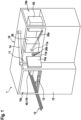
- Fig. 1 shows, by way of example, the basic structure of a first exemplary embodiment of the device 1 according to the invention for lens processing.
- the device 1 according to the invention serves for measuring and machining the edges of lenses to be processed, in particular in such a way that, according to predetermined production data and/or frame data, finished edge-machined lenses result, in particular for inclusion in spectacle frames (not shown).
- the device 1 preferably has a housing 10, which is preferably essentially divided into a measuring area 10a and a processing area 10b.
- the housing 10 serves in particular for occupational safety, e.g. with regard to tool or spindle breakage, sound insulation and protection against chip waste.
- the device 1 can be constructed in one piece or in multiple parts, in particular divided into a housing part for the measuring area 10a and a housing part for the processing area 10b (not shown). Accordingly, the device 1 according to the invention can be constructed on a single base frame or on a multi-part base frame, in particular a base frame part for the measuring area 10a and a base frame part for the processing area 10b (not shown).
- At least one measuring device 40, 110 is provided for measuring and/or aligning the lenses to be processed, while in the processing area 10b at least one processing device 50 is arranged for, in particular, machining the edges of the lenses.
- the measuring area 10a and the processing area 10b of the device 1 according to the invention are preferably separated from each other by a partition wall 11.
- the partition wall 11 is intended to at least minimize contamination of the measuring area 10a with the chip waste generated during the machining of the lenses.
- At least one conveyor device 30a, 30b passes through an opening 11a, 11b in the partition wall 11.
- the openings 11a, 11b are preferably provided with doors (not shown) that open the openings 11a, 11b before the passage of a lens transported by a conveyor device 30a, 30b and close them again after the passage.
- the at least one conveyor device 30a, 30b serves to transport the lenses to be processed from the at least one measuring device 40, 110, i.e. out of the measuring area 10a, to the at least one processing device 50 and to transport the finished processed lenses from the at least one processing device 50 back into the measuring area 10a of the device 1 according to the invention.
- an external conveyor belt 12 is arranged adjacent to the measuring area 10a on the housing 10, which serves to feed the lenses to be processed to the device 1 according to the invention or to transport the finished edge-processed lenses away from the device 1 according to the invention.
- the lenses are preferably placed in transport boxes 13.
- the external conveyor belt 12 can preferably form part of a larger and/or more complex conveyor system, in particular a linear or annular conveyor system, for transporting lens blanks as well as partially and fully processed lenses to and from various processing devices (not shown).
- a linear or annular conveyor system for transporting lens blanks as well as partially and fully processed lenses to and from various processing devices (not shown).
- other transport devices for the lenses are also conceivable instead of the external conveyor belt 12.
- an operating unit 14a attached to a pivot arm 14 is preferably arranged on the housing 10.
- the operating unit 14a preferably has a display device, in particular for displaying control menus and/or processing statuses of the lenses, and an input device, in particular for the preferably central input of control commands and/or display requests.
- the at least one conveyor device 30, the at least one measuring device 40, 110, and the at least one processing device 50 can be monitored by an operator and/or controlled via data input. Furthermore, the processing statuses of the lenses can be monitored.
- the pivot arm 14 serves to pivot the operating unit 14a in any direction to any side of the housing 10 of the device 1 according to the invention.
- the operating unit 14a can be designed to display different display and/or control menus, for example for the at least one measuring device 40 and/or the at least one processing device 50.
- the operation of the device 1 according to the invention can of course also be realized by means of differently constructed or designed operating devices, in particular by means of wireless operating devices such as tablets, laptops, etc., which can preferably also display different display and/or control menus, for example for the at least one measuring device 40 and/or the at least one processing device 50, depending on their location in relation to the housing 10 or to the at least one measuring device 40 and/or the at least one processing device 50.
- wireless operating devices such as tablets, laptops, etc.
- a control cabinet 15 accommodates, in a manner known per se, the components necessary for the power supply, operation and control of the device 1 according to the invention.
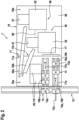
- Fig. 2 shows a top view of a second embodiment of the device 1' according to the invention.
- the housing 10 and the partition wall 11 between the measuring area 10a and the processing area 10b are only indicated for reasons of clarity.
- the external conveyor belt 12 serves to convey transport boxes 13 with lenses 16a, 16b to be processed for transport to the device 1' according to the invention as well as to convey transport boxes 13 with finished lenses 16b for transport away from the device 1' according to the invention.
- the transport crates 13 are provided with data carriers 13a, e.g., barcodes, RFID chips, or similar.
- the data carriers 13a can themselves contain production and/or frame data for the lenses 16a, 160 assigned to them to be processed. However, the data carriers 13a can also, for example, only contain identification data for the lenses 16a, 160 assigned to them, such as order numbers or the like.
- the production and frame data are stored, for example, in a control unit or a control center (see below) and linked to the respective identification data assigned to them.
- the conveyor belt 12 is preferably operatively connected to two buffer belts 17a, 17b arranged in the measuring area 10a of the device according to the invention, which form a buffer area 17.
- the buffer belts 17a, 17b can be designed, for example, as a roller conveyor or as a conveyor belt and, in the exemplary embodiment, offer space for up to eight transport crates 13.
- the buffer belt 17a preferably transports the transport boxes 13 away from the conveyor belt 12 and in the direction of arrow E into the measuring area 10a, while the buffer belt 17b transports the transport boxes 13 in the direction of arrow R out of the measuring area 10a in the direction of the conveyor belt 12.
- the transport crates 13 are pushed from the conveyor belt 12 onto the buffer belt 17a in a manner known per se, for example by means of a pusher 12a.
- the transport crates 13 are also advanced along the buffer belts 17a, 17b in a manner known per se, for example by means of stop devices 18 (see Figs. 6a, 6b).
- the stop devices 18 can, for example, also be designed as sliders which can be moved in a manner known per se transversely to the transport direction of the transport boxes 13 (i.e. transversely to the arrows E or R).
- a reading device 19 for example a laser scanner, is preferably provided (cf. Fig. 6a, 6b ), which reads out the manufacturing data and/or frame data stored on the data carriers 13a for the lenses 16a, 160 to be processed therein and transmits them to the control of the device 1' according to the invention.
- a slider (not shown) can also be provided to push the transport boxes 13 in a manner known per se transversely to the transport direction of the transport boxes 13 (i.e. transversely to the arrows E or R) from the buffer belt 17a to the buffer belt 17b.
- the buffer area 17 or the buffer belts 17a, 17b preferably serve as buffer storage for the transport boxes 13.
- lenses 16a, 160 to be processed are not necessarily fed for measurement and processing in the same order in which they enter the buffer belt 17a. Rather, lenses 16a, 160 arriving later can be measured and processed first, while lenses 16a, 160 arriving earlier are conveyed further in their transport boxes 13 along the arrows E and/or R until they are selected for measurement and processing by the control system of the device 1' according to the invention. Thus, lenses 16a, 160 arriving later can, so to speak, "overtake" lenses 16a, 160 already located in the buffer area 17 with regard to the order of their measurement and processing.
- This has the advantage, for example, that lenses 16a, 160 with an above-average measurement and/or processing time, e.g. lenses that are complex to measure and/or process, are only selected for measurement and processing when they slow down the overall process of lens measurement and lens processing within the device 1' according to the invention to the least extent possible.
- subsequent lenses 16a, 160 can be conveyed to a free measuring device 40, 110 and/or to a free processing device 50 after the shortest possible "waiting time” and thus be sent for measurement and processing.
- "dead times" at the at least one measuring device 40, 110 and the at least one processing device 50 are reduced as much as possible and, in the best case, completely avoided.
- a third conveyor belt (not shown) between the two buffer belts 17a, 17b, which is arranged parallel to the buffer belts 17a, 17b and basically consists, for example, of the WO 2013/131656 A2 is known.
- Such a third conveyor belt makes it possible, for example, to push transport crates 13 preferably from the buffer belt 17b onto the third conveyor belt, in particular by means of a known slider (not shown), if the lenses 16a, 160 accommodated in the transport crates 13 are not yet intended for measurement or processing.
- the third conveyor belt like the buffer belt 17a, would transport the transport crates 13 in the direction of arrow E.
- the transport crates 13 would then ultimately circulate on the third conveyor belt and the buffer belt 17b. Such circulation of the transport crates 13 is of course conceivable on the third transport and the buffer belt 17a. In this case, the third conveyor belt would transport the transport crates 13 in the direction of arrow R.
- two measuring devices 40, 110 are provided in the measuring area 10a, which are preferably of identical construction.
- Each of the measuring devices 40, 110 can measure a lens 16a, 160 to be processed, in particular so that the measured lenses 16a to be processed can be transferred in a conventional manner to the at least one processing device 50 in the correct spatial orientation in order to obtain finished edge-machined lenses 16b according to their respective production data and/or frame data.
- the two measuring devices 40, 110 are connected to two conveyor devices 30a, 30b.
- the transfer of the lenses 16a, 160 to be processed from their transport boxes 13 into a freely selectable measuring device 40, 110 from the measuring device 40 to a freely selectable conveyor device 30a, 30b as well as the transfer of the finished edge-processed lenses 16b from the conveyor devices 30a, 30b back into their transport boxes 13 is carried out via a handling device or device 20, as is shown by way of example in the Fig. 6a, 6b and 12 shown (see below).
- the conveyor devices 30a, 30b transport the measured and aligned lenses 16a to be processed, preferably while maintaining their spatial orientation, from the measuring area 10a into the processing area 10b of the device 1' according to the invention.
- the conveyor devices 30a, 30b preferably pass through openings 11a, 11b in the partition wall 11 between the measuring area 10a and the processing area 10b.
- the partition wall 11 is intended to at least minimize the contamination of the measuring area 10a with the chip waste generated during the machining of the edges of the lenses 16a.
- the openings 11a, 11b through which the conveyor devices 30a, 30b pass are preferably provided with doors (not shown) that open the openings 11a, 11b before a lens 16a, 16b transported by a conveyor device 30a, 30b passes through and close them again after the passage.
- two preferably identical processing devices 50 are provided in the processing area 10b, which are connected to the conveyor devices 30a, 30b.
- the lens 16a to be machined is first subjected to a first machining edge machining in the rough machining area 51, during which the desired contour of the lens 16a is approximately created.
- the thus pre-machined lens 16a is then preferably transferred to the finishing area 52, where the desired contour is completed.
- the now completely edge-machined lens 16b is then preferably transferred to a conveyor device 30a, 30b, transported back to the measuring area 10a of the device 1' according to the invention, and there deposited again in the associated transport box 13.
- a suction opening 69 can be provided, for example, in the bottom of the machining area 10b, to which a suction system with a pipe for conveying away the chip waste is connected in a manner known per se.
- the conveyor devices 30a, 30b and the processing devices 50 are attached to a support frame (not shown) spanning the processing area 10b in order to minimize contamination and enable trouble-free extraction of the chip waste.
- the floor of the processing area 10b can then also be designed, for example, in the form of a tray 68, in particular to simplify the collection of the chip waste in the area of the extraction opening 69. If necessary, the extraction process itself can also be designed to be discontinuous, thus saving energy and reducing noise.
- each processing device 50 preferably two lenses 16a can be processed at the same time, with one lens 16a in each case being located in the rough processing area 51 and one lens 16a in each case being located in the fine processing area 52. Therefore, in this exemplary embodiment of the device 1' according to the invention, two lenses 16a can preferably be measured and four lenses 16a can be edge-machined at the same time and/or in a time-overlapping manner.
- the housing 10 surrounds the measuring devices 40, 110, the conveying devices 30a, 30b, the handling device 20, the processing devices 50 and/or the buffer area 17, in particular laterally and/or completely.
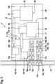
- Fig. 3 shows a plan view of a third embodiment of the device 1" according to the invention.
- the device 1" essentially corresponds to the device 1' according to Fig. 2 and has essentially the same components. Therefore, the same reference numerals have been used in this regard and reference is made to the above description.
- the essential difference between the device 1' according to the invention according to Fig. 2 and the device 1" according to the invention according to Fig. 3 is that the measuring devices 40, 110 are not arranged side by side, but offset from one another. Consequently, the conveyor devices 30a, 30b are arranged parallel to one another and each connect the measuring devices 40, 110 to a processing device 50.
- the transfer of the lenses 16a, 160 to be processed from their transport boxes 13 into a freely selectable measuring device 40, 110, from the measuring device 40, 110 to a freely selectable conveyor device 30a, 30b as well as the transfer of the finished lenses 16b from the respective conveyor device 30a, 30b back into their transport boxes 13 is carried out via a handling device or device 20, as shown by way of example in the Fig. 6a, 6b and 11 shown (see below).
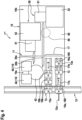
- Fig. 4 shows a plan view of a fourth embodiment of the device 1′′′ according to the invention.
- the device 1′′′ essentially corresponds to the device 1' according to Fig. 2 and has essentially the same components. Therefore, the same reference numerals have been used in this regard and reference is made to the above description.
- the essential difference between the device 1' according to the invention according to Fig. 2 and the device 1′′′ according to the invention according to Fig. 4 consists in the fact that several measuring devices 40, 110 are provided, two in the exemplary embodiment, to which a measuring table 42 is assigned for receiving the lenses 16a, 160 to be processed.
- the conveyor devices 30a, 30b are arranged parallel to one another and each connect the measuring table 42 to a processing device 50.
- the lenses 16a, 160 to be processed are removed from their transport boxes 13, placed on the measuring table 42 for measurement, and fed to the respective measuring devices 40, 110 by rotating the measuring table 42.
- the measured lenses 16a still to be processed are transferred to the conveyor devices 30a, 30b while maintaining their orientation; conversely, the finished lenses 16b are transported back to the measuring area 10a by the conveyor devices 30a, 30b and transferred to their assigned transport boxes 13.
- the transfer of the lenses 16a to be processed from their transport boxes 13 to the measuring table 42, from the measuring table 42 to a freely selectable conveyor device 30a, 30b as well as the transfer of the finished lenses 16b from the respective conveyor device 30a, 30b back to their transport boxes 13 is carried out via a handling device or device 20, as shown by way of example in the Figures 6a, 6b and 11 shown (see below).
- Fig. 5 shows a plan view of a fifth embodiment of the device 1 ⁇ according to the invention.
- the device 1 ⁇ essentially corresponds to the device 1' according to Fig. 2 and has essentially the same components. Therefore, the same reference numerals have been used in this regard and reference is made to the above description.
- the essential difference between the device 1' according to the invention according to Fig. 2 and the device 1 ⁇ according to the invention according to Fig. 5 consists in the fact that the measuring devices 40, 110 and the processing devices 50 are arranged rotated by 90°. This allows the housing to be shortened by 10', as indicated by the dot-dash line.
- the transfer of the lenses 16a, 160 to be processed from their transport boxes 13 into a freely selectable measuring device 40, 110, from the measuring device 40, 110 to a freely selectable conveyor device 30a, 30b as well as the transfer of the finished lenses 16b from the respective conveyor device 30a, 30b back into their transport boxes 13 takes place via a handling device or device 20, as is shown by way of example in the Fig. 6a, 6b and 11 shown (see below).
- FIG. 2 to 5 thus show by way of example the construction principle by which the device 1, 1', 1", 1′′′, 1 ⁇ according to the invention is characterized.
- This construction principle comprises the arrangement of at least one measuring device 40, 110 with at least one processing device 50 and their connection by means of at least one conveying device 30a, 30b.
- lenses 16a, 160 to be processed in the exemplary embodiment are measured and edge-machined in order to obtain finished lenses 16b according to defined production data and/or frame data, which can then be used in spectacle frames.
- the number of measuring devices 40, 110 and processing devices 50 to be combined can be selected arbitrarily, depending, for example, on the choice of design and/or function of the respective measuring devices 40, 110 and processing devices 50, their measuring or processing speed per lens 16a, 160, etc.
- the measuring devices 40, 110 and processing devices 50 can be arranged or oriented in any way relative to one another in the device 1, 1', 1", 1′′′, 1 ⁇ , for example depending on their size and/or their design.
- the design and number of conveyor devices 30a, 30b can then be selected depending on the number and, if applicable, also on the arrangement of the measuring devices 40, 110 and processing devices 50 in the respective device 1, 1', 1", 1′′′, 1 ⁇ .
- Two measuring devices 40, 110 and two processing devices 50 each with a rough machining area 51 and a fine machining area 52, were selected.
- this selection can be changed, varied, and/or expanded as desired. Therefore, the establishment of a buffer area 17 with buffer belts 17a, 17b is advantageous in order to keep sufficient lenses 16a to be machined and to quickly transport finished lenses 16b away in order to avoid delays in measuring and/or machining the lenses 16a, 160 to be machined.
- Fig. 6a, 6b and 12 show an embodiment of a handling device or apparatus 20 for lenses 16a, 160 16b.
- the handling device or apparatus 20 is assigned to the measuring area 10a of the device 1, 1', 1", 1 "', 1"" according to the invention.
- Fig. 6a shows the handling device or device 20 in a plan view or in the direction of the arrows VIa, VIa in Fig. 6b .
- Fig. 6b the handling device or device 20 in a side view or in the direction of the arrows VIb, VIb in Fig. 6a .
- the Fig. 6a, 6b further show the stop devices 18 arranged between the buffer belts 17a, 17b for controlling the advance of the transport boxes 13 for the lenses 16a, 16b, 16b on the buffer belts 17a, 17b.
- Fig. 6a, 6b Finally, they also show a reading device 19 for reading the production data and/or frame data stored on the data carriers 13' for the lenses 16a, 160 to be processed, which are located in the associated transport boxes 13.
- the handling device or apparatus 20 comprises a first handling unit 20a.
- the first handling unit 20a preferably serves, on the one hand, for transferring lenses 16a, 160 to be processed from their associated transport boxes 13, which are located in particular on the buffer belts 17a, 17b, to lens holders 41, 134 assigned to the respective measuring devices 40, 110.
- the first handling device or handling unit 20a also preferably serves to transfer finished lenses 16b from the conveyor devices 30a, 30b back to their respective transport boxes 13 assigned to them (see below).
- the first handling unit 20a in the exemplary embodiment preferably has a first rail 21 with two guides 21a, 21b, on which a second rail 22 is arranged at right angles and guided in the guides 21a, 21b in a manner known per se.
- the second rail 22 is movable in a direction indicated by the arrow L (in the direction of the x-coordinate) along the first rail 21 - in the exemplary embodiment electrically driven by a motor 29a.
- a gripping device 23 movable in a direction indicated by the arrow M (in the direction of a y-coordinate) - in the exemplary embodiment electrically driven by a motor 29b - is arranged and guided on the second rail 22.
- the gripping device 23 has a gripper or suction device 24 - pneumatically driven in the exemplary embodiment - movable in a direction indicated by the arrow N (in the direction of a coordinate z) for gripping or sucking the lenses 16a, 16b.
- the handling device or apparatus 20 further preferably comprises a second handling unit 20b.
- the second handling unit 20b serves in particular for transferring measured lenses 16a, which are still to be processed, from the lens holders 41, 134 assigned to the respective measuring devices 40, 110 to the freely selectable conveyor devices 30a, 30b (see also Fig. 11 ).
- the second handling unit 20b in the exemplary embodiment preferably has a first rail 25, on which a second rail 26 is arranged and guided in a manner known per se.
- the second rail 26 is movable in a direction indicated by the arrow O (in the direction of a coordinate y) along the first rail 25, in the exemplary embodiment by means of an electric drive motor 29c.
- a gripping device 27 is arranged on the second rail 26 in a direction indicated by the arrow P (in the direction of a coordinate x) - in the exemplary embodiment electrically movable by means of a motor 29d. and guided in a manner known per se.
- the gripping device 27 has a gripper or suction device 28—pneumatically driven in the exemplary embodiment—movable in a direction indicated by the arrow Q (in the direction of a coordinate z) for gripping or sucking the lenses 16a.
- the handling units 20a, 20b of the handling device or apparatus 20 are preferably attached to a support frame (not shown) of the device 1, 1', 1", 1′′′, 1 ⁇ according to the invention.
- the at least one measuring device 40, 110 can be of any design and operate, for example, by mechanical scanning or non-contact scanning.
- the at least one measuring device is designed for non-contact measurement of the lenses to be processed using deflectometry and/or transmission measurement and/or luminescence radiation.
- each lens 16a to be processed is accommodated in a lens holder 41.
- the device 110 comprises at least a first radiation source 140, optionally a further radiation source 140' with an upstream slit diaphragm or mask 143' for generating a radiation pattern, a second radiation source 150 and/or a measuring and/or detection device 120.
- the orientation of a measuring and/or detection unit e.g. the camera lens 123 of a camera 122 of the measuring and/or detection device (see below) defines a measuring axis M'.
- An opening 124 in the holder 121 and a recess 114 in the holding table provide a free measuring path in the vertical direction for the camera lens 123, thereby defining a vertically extending measuring axis M'.
- the two groups 140a, 140b of laser diodes 141 are again arranged at right angles to each other.
- the laser diodes 141 are connected to a power supply device (not shown) via lines 142 in such a way that they can be switched independently of each other and in any combination.
- a mounting plate 151 for accommodating a second radiation source 150 is preferably arranged below the drive unit 116 for the rack and pinion gear.
- a TFT-based liquid crystal flat screen is provided as the second radiation source 150.
- the second radiation source 150 is preferably arranged above the gripping device 134 and arranged in a plane oriented perpendicular to the z'-axis or the measuring axis M'.
- the measuring device 110 can also consist of two parts, each with a camera 122, a first radiation source 140, and a second radiation source 150, as described above.
- a gripping and centering arrangement 144 can then be provided, as shown, for example, in Fig. 10 is shown.
- the pairs 145 of gripping devices 134 are each rotatable about a preferably vertical axis, in particular by 180°, particularly preferably such that upon rotation by 180°, the gripping devices 134 of a pair exchange their positions.
- the rotating device 146 forms the rotation axis for the pair 145.
- the rotating device 146 is preferably arranged below the gripping devices 134 and/or between two of the two gripping devices 134 of the pair 145.
- Each pair 145 of gripping devices 134 is preferably assigned a respective storage table 137, as described above.
- each storage table 137 is designed to be height-adjustable by means of an adjusting device 147 and/or is arranged or can be arranged such that it is in a loading position according to Fig. 8 (right half of Fig. 10 ) or in a measuring position according to Fig. 9 (left half of Fig. 10 ) is located.
- the gripping device 134 which is arranged in the background of the image, is preferably positioned with respect to the elements associated with it, camera 122, first radiation source 140 and/or second radiation source 150, in such a way that a measurement (described in more detail below) can take place.
- the front gripping device 134 can be loaded or unloaded with a lens 160 to be measured, as described below, while a lens (not shown) is held and measured in the rear gripping device 134.
- a lens 160 to be measured can be held in the front gripping device 134 and a fully measured lens 160 can be held in the rear gripping device 134 (not shown), so that this pair 145 can be rotated 180°. Then, the lens 160 to be measured can be measured as described below, while the fully measured lens 160 can be unloaded as described below.
- the gripping device 134 of the device 110 is preferably in its loading position (cf. Fig. 8 , Fig. 10 right).
- the storage table 137 is preferably arranged directly below the gripping device 134.
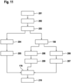
- the device 110 is operated in a manner known per se (cf. WO 2016/095939 A1 ) in method step 201 with an optically active element to be measured, in the exemplary embodiment a lens 160, possibly provided with a coating 160', for example for a spectacle lens, by placing the lens on the support table 137.
- the lens 160 is preferably oriented such that its underside 162, which is concave in the exemplary embodiment, is directed towards the camera lens 123 and its upper side 161, which is convex in the exemplary embodiment, is directed towards the second radiation source 150.
- the gripping elements 135 are first actuated such that the lens 160 is centered along its circumference within the gripping device 134 with respect to the latter.
- the gripping elements 135 of the gripping device 134 are actuated such that the lens 160 is held in a clamping manner by means of the gripping elements 135, wherein the centering of the lens 160 is substantially maintained.
- the gripping device 134 is first moved upwards along the z'-axis so far that the support table 137 can be pivoted out of the measuring range of the camera lens 123 of the camera 122 in order to clear the measuring axis M' for the camera lens 123.
- the gripping device 134 together with the lens 160 clamped therein, is displaced further upwards along the z'-axis in the direction of the second radiation source 150 by means of the rack and pinion gear.
- the gripping device 134 of the device 110 according to the invention is now in a defined measuring position (cf. Fig. 9 , Fig. 10 (left). This measuring position can remain unchanged regardless of the properties of the optically active element to be measured in order to contribute to the standardization of the method according to the invention.
- the linking of these measurement data allows the determination of a planar evaluation of the refractive power of lens 160 (so-called "power map") in method step 210.
- This makes it possible, among other things, to distinguish between prisms incorporated into lens 160 as ordered and prism errors. This applies both to prism errors that arose during the shaping of the underside 162 of lens 160 and to prism errors that are detected due to incorrect positioning of lens 160 in device 110.
- the methods described above for determining the spatial position of lens 160 (point 1) and for determining its parameters (point 2) can also be performed deflectometrically.
- radiation emitted by a radiation source is used, to which lens 160 is opaque.
- the radiation source is positioned such that lens 160 reflects the radiation emitted by the radiation source in the direction of the measurement axis M', i.e., in the direction of camera lens 123, so that the resulting reflected radiation can be captured by camera lens 123 and detected by the CCD sensor of camera 122.
- the resulting measurement data is then evaluated in a conventional manner.
- Fig. 12 and 13 show in a plan view an embodiment of conveying devices 30a, 30b, which preferably interact with the handling device or device 20 in the measuring area 10a and/or the two processing devices 50 in the processing area 10b of the device 1, 1', 1", 1′′′, 1 ⁇ according to the invention.
- the conveying devices 30a, 30b are designed as linear conveyors 31a, 31b and are preferably fastened to a support frame (not shown) of the device 1, 1', 1", 1′′′, 1 ⁇ according to the invention.
- each linear conveyor 31a, 31b has, in a manner known per se, a guide rail 32a, 32b for guiding a carriage 33.
- the carriage 33 is pneumatically driven and movable on the guide rail 32a, 32b in the direction of arrow S (conveyor device 30a) or in the direction of arrow T (conveyor device 30b).
- the carriage 33 can also be electrically driven.
- a rigid holder 34 with a first gripper or suction cup 34a and/or a holder 35 pivotable about a pivot axis D with a second gripper or suction cup 35a are arranged on the carriage 33.
- the first gripper or suction cup 34a preferably serves to hold the lens 16a that has been measured and aligned for edge processing, while the second gripper or suction cup 35a preferably serves to hold the finished edge-processed lens 16b.
- the first gripper or suction cup 34a is preferably designed in a manner known per se such that it can receive the lens 16a, which has been completely measured and aligned for edge processing, in its respective orientation and that this orientation is maintained during the transport of the lens 16a to the processing device 50.
- the second gripper or suction cup 35a can be designed simply so that it can pick up the finished edge-machined lens 16b in any orientation.
- the axes x, y and z mentioned below are oriented orthogonally to each other in the exemplary embodiment, preferably with the x-axis and the y-axis running horizontally and the z-axis running vertically (see also Fig. 6a, 6b ).
- Fig. 13 to 14b show an embodiment of a processing device 50 according to the invention, which is preferably suitable for use in the device 1, 1', 1", 1′′′, 1 ⁇ according to the invention and/or for carrying out the method according to the invention.
- a processing device 50 according to the invention which is preferably suitable for use in the device 1, 1', 1", 1′′′, 1 ⁇ according to the invention and/or for carrying out the method according to the invention.
- two identical processing devices 50 according to the invention are provided.
- the two processing devices 50 are fastened to a support frame (not shown), in particular at a distance from the tub 68 or the suction opening 69, in order to ensure trouble-free drainage of the chip waste.
- Each processing device 50 preferably has a rough processing area 51 and a fine processing area 52, so that two lenses 16a can be edge-processed simultaneously and/or in an overlapping manner.
- the processing device 50 is preferably designed for the simultaneous processing of lenses in the rough processing area 51 and the fine processing area 52.
- the rough machining area 51 also serves as a loading area for lenses 16a to be machined or as an unloading area for finished edge-machined lenses 16b.
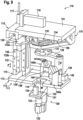
- two workpiece spindles or one-piece spindle housings 53 are provided in each machining device 50.
- the two workpiece spindles or one-piece spindle housings 53 are arranged in the exemplary embodiment such that they can be rotated by 180° about a rotation axis Tr in the exemplary embodiment.
- the workpiece spindles 53 or one-piece spindle housings 53 are arranged on a rotating device 54, in particular offset from one another.
- each workpiece spindle or one-piece spindle housing 53 is arranged to be transferable from the rough machining area 51 to the fine machining area 52 and back.
- the preferred offset arrangement of the two workpiece spindles or one-piece spindle housing 53 results in the radius ("flight circle") defined by the rotation of 180° being minimized.
- the machining device 50 has a spindle device with two workpiece spindles 53, which are connected in particular by the one-piece spindle housings 53 are formed.
- the workpiece spindles or one-piece spindle housings 53 are preferably each designed to hold a lens during machining.
- the spindle device with the workpiece spindles 53 is preferably rotatable, so that the workpiece spindles 53 can be moved from the rough machining area 51 to the fine machining area 52 and vice versa.
- the workpiece spindles or one-piece spindle housings 53 are arranged at a fixed distance from one another.
- the spindle device with the workpiece spindles or the one-piece spindle housing 53 is preferably rotatable about a particularly vertical axis of rotation and/or by means of the rotating device 54, in particular by 180°.
- Each workpiece spindle or one-piece spindle housing 53 preferably has a workpiece spindle, in particular in the form of two half-spindles, namely an upper half-spindle 55 and a lower half-spindle 56.
- both half-spindles 55, 56 are designed to be driven in the same direction of rotation in a conventional manner by an electric motor via a synchronous shaft with two belts (not shown) operatively connected to the synchronous shaft.
- the two half-spindles 55, 56 can also be designed to be driven in the same direction of rotation, for example, by means of respective associated electric motors (not shown).
- the lower half-spindle 56 in contrast to the upper half-spindle 55, is designed to be vertically displaceable in the direction of the z-axis, so that a lens 16a to be machined can be clamped between the upper half-spindle 55 and the lower half-spindle 56 on both surfaces (not shown).
- an adhesive force transmitted by the upper half-spindle 55 and the lower half-spindle 56 acts on both surfaces of the lens 16a to be machined.
- each half-spindle 55, 56 further comprises an adhesive element (not shown) such that the surfaces of the lens 16a to be machined are held clamped between the adhesive elements.
- the adhesive elements are preferably made of an elastic plastic material that adapts to the respective surface contours of the lens 16a. It is advantageous if the half-spindles 55, 56, as provided in the exemplary embodiment, are designed to rotate in the same direction about the rotation axis C and are separately drivable. This adds up the torques transmitted by the electric motor(s), ensuring particularly secure grip of the lens 16a to be machined during edge machining.
- the rough machining area 51 further preferably has exactly one tool spindle or tool spindle device 57 for receiving exactly one tool 58 for machining the edge of the lens 16a to be machined, in particular held by the associated half-spindles 55, 56.
- the tool spindle device 57 is mounted on an x-slide 59a and/or a z-slide 59b such that it is movable along a vertical z-axis and/or a horizontal x-axis. This allows the tool 58 to be advanced toward the lens 16a to be machined in the x-direction and/or the z-direction.
- the tool spindle device 57 preferably does not have a pivot axis.
- additional axes of movement including pivot axes, can be provided for advancing the tool 58.
- the tool 58 can be designed with a comparatively small length dimension in order to minimize machining errors, for example due to natural vibrations or bending of the tool 58, as well as the risk of damage to the tool 58.
- a measuring device 60 with known measuring probes 61 is preferably also provided.
- the measuring device 60 is preferably held together with the tool spindle device 57 on the x-slide 59a and/or the z-slide 59b in such a way that, as described above for the tool spindle device, it is also movable in the x-direction and/or in the z-direction, so that the infeed of the measuring probe 61 to the lens 16a can take place accordingly.
- the measuring device 60 is used to measure the approximately edge-machined lens 16a before transfer to the fine machining area 52 of the machining device 50.
- the position of the upper and lower surfaces of the edge region of the approximately edge-machined lens 16a remaining after the rough machining is determined in space.
- the measuring probes 61 move on the surfaces between the obtained contour of the approximately edge-machined lens 16a and the calculated contour of the desired finished lens 16b. On this basis, the specific manufacturing data for the fine machining of the approximately edge-machined lens 16a can be determined.
- the fine machining area 52 preferably has several, in the exemplary embodiment five, preferably different tools 62 for machining a lens 16a to be machined.
- Each tool 62 is fixedly mounted on a tool spindle 63 and is preferably intended for a single, defined machining task. However, combination tools may also be provided, which may be intended for two or more machining tasks.
- the tools 62 are preferably selected such that all lens rim types (particularly for spectacles with full frames, half frames, and/or rimless spectacles) can be produced.
- different tools 62 are provided for different processing tasks.
- the tool spindles 63 are accommodated in a holding device 64 in any order.
- the tool spindles 63 are accommodated in such a way that that they can be easily replaced and/or their order can be changed.
- the holding device 64 is preferably pivotably mounted in an x-carriage 65a about a horizontally extending axis, thereby defining a pivot axis B.
- the x-carriage 65a is in turn designed to be movable along an x-axis.
- the x-carriage 65a is in turn preferably held on a y-carriage 65b, which is designed to be movable along a y-axis extending at a right angle to the x-axis.
- the y-carriage 65b is preferably held on a z-carriage 66 which is designed to be movable along a z-axis arranged perpendicular to the plane formed by the x-axis and the y-axis.
- the tool spindles 63 with their tools 62 are preferably movable in all three spatial directions x, y, z and additionally around the pivot axis B and are thus designed to be adjustable to the respective lens 16a to be machined held by the associated half-spindles 55, 56.
- the tools 62 can be selected independently of one another for fine machining of the lens 16a to be machined and can be individually advanced to the already roughly machined lens 16a held in the associated one-piece spindle housing 53 by means of a linear movement in the y-direction and then brought into engagement with the lens 16a by means of a pivoting movement about the pivot axis B. This enables complete edge machining of the lens 16a to be machined, producing finished edge-machined lenses 16b of all sizes and/or with a wide variety of edge shapes.
- This construction according to the invention allows edge machining of the lens 16a to be machined with different tools 62, wherein according to the invention there is preferably no time-consuming tool change, but the respectively required tool 62 is advanced by means of a linear displacement and a subsequent pivoting movement of the holding device 64 of the lens 16a to be machined.
- the delivery paths for the tools 62 are very short, so that the delivery movements themselves can also be carried out very quickly.
- the tools 62 can be activated, i.e. set in rotational movement, before the completion of the previous edge processing step, i.e. before they are advanced to the lens 16a to be processed.
- the device 1, 1', 1", 1′′′, 1 ⁇ according to the invention has an integrated control system, specifically for all controllable components of the device 1, 1', 1", 1′′′, 1 ⁇ according to the invention, in particular for the buffer system 17, the handling device or device 20, the at least one conveying device 30, the at least one measuring device 40 and/or the at least one processing device 50.
- An embodiment of the method according to the invention can be carried out with the exemplary device according to the invention just described and preferably has the following method steps.
- transport crates 13 are transported into the area of the device 1, 1', 1", 1"', 1"" according to the invention by means of the conveyor belt 12.
- Each transport box 13 contains at least one, expediently two lenses 16a, 16b to be processed, which are assigned to it, preferably wherein each transport box is provided, for example, with identification data or with the manufacturing data and/or frame data 13a of the lenses to be processed which are assigned to it.
- the lenses 16a, 16b and/or transport boxes 13 can also be transported to the device 1, 1', 1", 1′′′, 1 ⁇ and away from the device 1, 1', 1", 1′′′, 1 ⁇ in other ways.
- the transport boxes 13 are preferably pushed one after the other from the conveyor belt onto the buffer belt 17a by means of the slider 12a.
- Each transport box 13 then preferably first passes through a reader 19, which reads the identification data or the production data and/or frame data 19 and forwards them to the control of the device 1, 1', 1", 1"', 1 ⁇ .
- the further transport of each transport box 13 on the buffer belt 17a into the measuring area 10a of the device 1, 1', 1", 1′′′, 1"" according to the invention is preferably controlled by stop devices 18 which, in a manner known per se, allow the further transport of each transport box 13 in sections depending on the control of the device 1, 1', 1", 1′′′, 1 ⁇ .
- a transport box 13 When a transport box 13 has reached the end of the buffer belt 17a, it can be pushed onto the buffer belt 17b extending parallel to the buffer belt 17a, for example in a manner known per se by means of a slider.
- each transport box 13 on the buffer belt 17b out of the measuring area 10a of the device 1, 1', 1", 1"', 1"" according to the invention is preferably controlled by stop devices 18 which are provided with a locking device in a manner known per se and allow the further transport of each transport box 13 in sections depending on the control of the device 1, 1', 1", 1′′′, 1 ⁇ .
- the lenses 16a to be processed assigned to them are removed from the transport boxes 13, in particular by means of the handling device or apparatus 20, and fed to the further processes within the device 1, 1', 1", 1"', 1 ⁇ according to the invention.
- the finished edge-processed lenses 16b are returned to the transport boxes 13 assigned to them and placed therein, in particular by means of the handling device or apparatus 20.
- a transport box 13 At the latest when a transport box 13 has reached the end of the buffer belt 17b in the area of the conveyor belt 12, it is equipped with the finished edge-machined lenses 16b assigned to it and is pushed back onto the conveyor belt 12 by means of the following transport boxes 13 and/or transported out of the area of the device 1, 1', 1", 1"', 1"" according to the invention.
- the lenses 16a it is preferably not necessary for the lenses 16a to be processed to be removed in the order of the transport crates 13 arriving on the buffer belt 17a.
- the control of the device 1, 1', 1", 1′′′, 1 ⁇ preferably calculates the sequence of removal of the lenses 16a to be processed from their transport boxes 13 in such a way that the lenses 16a to be processed are removed from their respective transport boxes 13 depending on the capacity utilization of the at least one measuring device 40 and/or the at least one processing device 50.
- This means that the lenses 16a to be processed can be measured, aligned, and edge-machined at an optimal speed, in particular without waiting times, for example caused by a leading lens 16a with a long measuring and/or processing time.
- Both the lenses 16a to be processed and the finished, edge-processed lenses 16b can preferably be removed from their transport boxes 13 or placed in their transport boxes, regardless of the position of their respective assigned transport boxes 13 on the buffer belts 17a, 17b. At the latest when a transport box 13 has reached the end of the buffer belt 17b in the area of the conveyor belt 12, it must be reloaded with the finished, edge-processed lenses 16b assigned to it.
- additional circulation of the transport boxes can be enabled by means of a third conveyor belt (not shown) in order to optimize the buffering effect of the buffer belts 17a, 17b.
- a lens 16a to be processed from its transport box 13 After removing a lens 16a to be processed from its transport box 13, it is transported by the handling unit 20a to the measuring system 40 or the respective measuring device 40 that is available at that time.
- the lens 16a is placed on a support table assigned to the respective lens holder 41 with its convex surface facing upwards, so that the lens 16a can be fixed in a conventional manner by the clamping devices of the lens holder 41 and transferred to the measuring device 40, as is the case, for example, in the WO 2016/095939 A1 described.
- the lens 16a to be machined is measured in a conventional manner.
- the measured lens 16a is preferably picked up by the handling unit 20b at its convex surface at the calculated block point and released from the clamping devices of the lens holder 41.
- the lens 16a to be processed is then aligned in a manner known per se, for example as shown in the WO 2016/095939 A1 described.
- the controller then preferably decides to which conveyor device 30a, 30b the measured and preferably aligned lens 16a will be transferred, particularly while maintaining its alignment. This preferably depends on which processing device 50 assigned to the respective conveyor device 30a, 30b can be reloaded at this time.
- the aligned lens 16a is accordingly transferred from the handling unit 20b to the suction cup/gripper 34a of the selected conveyor device, while maintaining its alignment, which now preferably grips it on its concave surface.
- the handling unit 20a grips a finished lens 16b held by the suction cup/gripper 35a of the selected conveyor device 30a, 30b on its concave surface, removes it from the suction cup/gripper 35a and places it in the transport box 13 assigned to it.
- the carriage 33 of the selected conveyor device 30a, 30b moves along the guide rail 32a, 32b from the measuring area 10a of the device 1, 1', 1", 1′′′, 1"", 1 ⁇ according to the invention into its processing area 10b and in doing so preferably passes the partition wall 11 through the opening 11a, 11b.
- the door assigned to the respective opening 11a, 11b preferably opens so that the carriage 33 can pass through the opening 11a, 11b.
- the opening 11a, 11b is then preferably closed again by the door assigned to it.
- a finished lens 16b transferred from a workpiece spindle or a one-piece spindle housing 53 to the conveyor device 30a, 30b.
- the suction cup/gripper 35a moves under the upper half-spindle 55 of the workpiece spindle or the one-piece spindle housing 53 and picks up the finished lens 16b held on the upper half-spindle 55 by its concave surface.
- the pivotable holder 35 then folds away in the direction of rotation D, allowing the suction cup/gripper 34a to move under the upper half-spindle 35 of the workpiece spindle or the one-piece spindle housing 53.
- the lens 16a to be machined is picked up by the upper half-spindle 55 while maintaining its alignment and is then released from the suction cup/gripper 34a.
- the carriage 33 now moves away and transports the finished lens 16b back into the measuring area 10a of the device 1, 1', 1", 1 "', 1"", according to the invention, wherein it preferably again passes through the opening 11a, 11b in the partition wall 11 as described above.
- the lower half spindle 56 of the one-piece spindle housing 53 moves up so that the lens 16a to be machined is fixed in its predetermined orientation and the edge machining can begin.
- another lens 16a is held in the spindle housing 53 located on the fine machining area 52 of the edge machining device 50 and is subjected to final edge machining.
- the tool spindles 63 can be raised before the lens 16a is transferred to the fine machining area 52 in order to keep the machining time as short as possible.
- the fine machining of the lens 16a to be machined generally takes longer than its rough machining.
- the number and/or design and/or sequence of the tools 62 are expediently selected so that the edge machining of the lenses 16a to be machined can be carried out as time-efficiently as possible. Since the tools 62 have different feed paths along the y-axis, a corresponding sequence or arrangement in the holder 64 can result in an overall minimal travel path of the holder 64, which in turn can shorten the machining time.
- the handling unit 20a grasps the finished lens 16b held on the concave side by the suction cup/gripper 35a, removes it from the suction cup/gripper 35a, and places it in the transport box 13 assigned to it.
- another measured and aligned lens 16a to be processed is transferred to the suction cup/gripper 34a, maintaining its alignment, which then grasps it on the concave side.
- This further lens 16a is now transferred into the processing area 10b of the device 1, 1', 1", 1"', 1 ⁇ according to the invention as described above.
- the lens 16b which is currently located in the fine machining area 52 of the machining device 50, has been completely edge-machined.
- the finished lens 16b is transferred to the rough machining area 51 of the machining device 50 and the lens 16a, which has been pre-machined as described above, is transferred to the fine machining area 52.
- the finished lens 16b waits for its pickup by the carriage 33 as described above. The described cycle begins again.
- all measuring devices 40, 110 can be equipped in any order with lenses 160 to be measured or lenses 16a to be processed.
- each conveyor device 30a, 30b can be equipped in any order with a measured and aligned lens 16a to be processed.
- the control Based on the production data and/or frame data of the lenses 16a to be processed, which may have been read out by the reading device 19 and transmitted to the control of the device 1, 1', 1", 1", 1 ⁇ according to the invention or stored there, the control preferably calculates both the sequence in which the lenses 16a are processed and the selection of the respective measuring device 40, 110 and the respective conveyor device 30a, 30b and the respective processing device 50 for each individual lens 16a to be processed. This calculation is carried out in particular in such a way that an optimal temporal sequence of the Measurement, conveying and edge processing of the respective lens to be processed, in particular with as little waiting time as possible.
- a control or monitoring device suitable for the method according to the invention is in particular capable of managing processing statuses for the lenses 16a to be processed.
- the specific measuring device 40, 110 and/or processing device 50 to be used is preferably freely selected for each lens 16a, i.e. independently of any other existing measuring device 40, 110 and/or processing device 50.
- the actual processing status of each lens 16a is reflected in the processing status.
- the processing status indicates, for example, which measurement or processing has already been performed or is to be performed next, whereby this is particularly preferably done with reference to the corresponding processing plan for each lens 16a.
- a control or monitoring device suitable for the method according to the invention is further preferably suitable for managing, for each lens 16a, its individual measuring time in a measuring device 40, 110 as well as its individual processing time in a processing device 50 and/or for determining the occupancy time for each measuring device 40, 110 and processing device 50, i.e. the period of time during which the respective measuring device 40, 110 and the respective processing device 50 is blocked by the respective lens 16a.
- the control or monitoring device can determine the sequence of measuring and processing of the lenses 16a.
- the determination is preferably made in such a way that the measuring device(s) 40, 110 and the Processing device(s) 50 can be operated as far as possible without downtime.
- the determination is particularly preferably made such that the sequence of measuring and processing the lenses 16a is determined independently of the order in which their respective transport boxes are arranged on the buffer belts 17a, 17b.
- the two processing devices 50 can be controlled independently of one another, loaded with a lens 16a to be processed or unloaded from a finished edge-processed lens 16b.
- the measurement and edge processing of lenses 16a to be processed can thus be carried out according to the invention in such a way that lenses 16a to be processed easily and complexly can be optimally distributed between the measuring devices 40 and processing devices 50, respectively, so that they can be measured or edge-processed with the least possible expenditure of time or loss of time.
- control of the device according to the invention has the respective production or frame data of the lenses 16a to be processed.
- the handling device or device 20 and/or the conveyor devices 30a, 30b can thus be controlled in such a way that the lenses 16a to be processed are distributed in an optimal manner among free measuring devices 40 and/or conveyor devices 30a, 30b and/or processing devices 50 in order to achieve the most time-saving measurement and/or edge processing possible.
- the lens data required for this purpose e.g. processing data, processing plans, processing sequences, processing steps, optical data and/or geometric data, are either stored in the control or monitoring device by means of a storage medium and/or are read out from the data carriers 13a when the respective transport box 13 enters, as described above.
- the detection of the respective processing statuses of the individual lenses 16a, 16b located in the device according to the invention thus serves to control, coordinate and organize the sequence of the individual measuring and processing processes in the respective measuring device(s) 40, 110 and processing device(s) 50.
- processing statuses can alternatively or additionally be transmitted to an external monitoring system or control center, stored by the system, and/or displayed to an operator.
- This allows, for example, the measuring device 40, 110 used to measure each individual lens 16a, 16b and the processing device 50 used to process it to be recorded and stored.
- Such data acquisition can be particularly useful for troubleshooting and/or error correction if a finished lens 16b does not correspond to the assigned manufacturing and/or frame data.
- Fig. 15 represents in particular a graphical representation or reproduction of the processes 1a-6g listed in Table 1.
- Fig. 15 The simultaneous processing in two stations is shown, whereby the Fig. 15 as “Station 1" and “Station 2" correspond to two processing devices 50 of identical construction.
- the device 1, 1', 1", 1′′′, 1"" according to the invention and the method according to the invention therefore preferably allow the edge processing of lenses with a throughput of at least 100 lenses per hour.
- a throughput of up to 250 lenses per hour can be achieved.
Landscapes
- Engineering & Computer Science (AREA)
- Mechanical Engineering (AREA)
- Physics & Mathematics (AREA)
- Chemical & Material Sciences (AREA)
- Analytical Chemistry (AREA)
- General Physics & Mathematics (AREA)
- Geometry (AREA)
- Ophthalmology & Optometry (AREA)
- Manufacturing & Machinery (AREA)
- Health & Medical Sciences (AREA)
- Ceramic Engineering (AREA)
- Inorganic Chemistry (AREA)
- Grinding And Polishing Of Tertiary Curved Surfaces And Surfaces With Complex Shapes (AREA)
- Length Measuring Devices By Optical Means (AREA)
- Eyeglasses (AREA)
Applications Claiming Priority (4)
| Application Number | Priority Date | Filing Date | Title |
|---|---|---|---|
| DE102018006980 | 2018-09-04 | ||
| DE102018007463.4A DE102018007463B4 (de) | 2018-09-04 | 2018-09-21 | Vorrichtung und Verfahren zur Linsenbearbeitung sowie Bearbeitungseinrichtung für Linsen |
| EP19765232.4A EP3847416B1 (fr) | 2018-09-04 | 2019-09-04 | Appareil de traitement de lentille |
| PCT/EP2019/073599 WO2020049052A2 (fr) | 2018-09-04 | 2019-09-04 | Dispositif et procédé pour l'usinage de lentilles ainsi que moyen d'usinage et dispositif de mesure pour lentilles |
Related Parent Applications (1)
| Application Number | Title | Priority Date | Filing Date |
|---|---|---|---|
| EP19765232.4A Division EP3847416B1 (fr) | 2018-09-04 | 2019-09-04 | Appareil de traitement de lentille |
Publications (2)
| Publication Number | Publication Date |
|---|---|
| EP4523897A2 true EP4523897A2 (fr) | 2025-03-19 |
| EP4523897A3 EP4523897A3 (fr) | 2025-10-01 |
Family
ID=93395721
Family Applications (1)
| Application Number | Title | Priority Date | Filing Date |
|---|---|---|---|
| EP24209492.8A Pending EP4523897A3 (fr) | 2018-09-04 | 2019-09-04 | Dispositif d'usinage de lentilles |
Country Status (5)
| Country | Link |
|---|---|
| US (1) | US20260034632A1 (fr) |
| EP (1) | EP4523897A3 (fr) |
| CN (1) | CN118951952A (fr) |
| HU (1) | HUE069843T2 (fr) |
| SM (1) | SMP201900014B1 (fr) |
Citations (5)
| Publication number | Priority date | Publication date | Assignee | Title |
|---|---|---|---|---|
| DE4127094A1 (de) | 1991-08-16 | 1993-02-18 | Wernicke & Co Gmbh | Brillenglasschleifmaschine |
| WO2001070460A1 (fr) | 2000-03-18 | 2001-09-27 | Wernicke & Co. Gmbh | Systeme d'usinage des bords de verres de lunettes |
| US20070264915A1 (en) | 2004-12-03 | 2007-11-15 | Essilor International | Device for Automatically Preparing Ophthalmic Lenses for Mounting, Enabling a Plurality of Lenses to be Taken in Charge Simultaneously |
| WO2013131656A2 (fr) | 2012-03-09 | 2013-09-12 | Schneider Gmbh & Co. Kg | Installation et procédé permettant d'usiner des lentilles optiques |
| WO2016095939A1 (fr) | 2014-12-19 | 2016-06-23 | Schneider Gmbh & Co. Kg | Procédé et dispositif d'usinage d'une lentille optique |
Family Cites Families (1)
| Publication number | Priority date | Publication date | Assignee | Title |
|---|---|---|---|---|
| DE102008023093A1 (de) * | 2008-05-09 | 2009-11-12 | Satisloh Ag | Vorrichtung zum Blocken von Werkstücken, insbesondere Brillengläsern, für deren Bearbeitung und/oder Beschichtung |
-
2019
- 2019-01-14 SM SM20190014A patent/SMP201900014B1/it unknown
- 2019-09-04 HU HUE19765232A patent/HUE069843T2/hu unknown
- 2019-09-04 CN CN202411011353.1A patent/CN118951952A/zh active Pending
- 2019-09-04 EP EP24209492.8A patent/EP4523897A3/fr active Pending
-
2025
- 2025-10-10 US US19/355,107 patent/US20260034632A1/en active Pending
Patent Citations (5)
| Publication number | Priority date | Publication date | Assignee | Title |
|---|---|---|---|---|
| DE4127094A1 (de) | 1991-08-16 | 1993-02-18 | Wernicke & Co Gmbh | Brillenglasschleifmaschine |
| WO2001070460A1 (fr) | 2000-03-18 | 2001-09-27 | Wernicke & Co. Gmbh | Systeme d'usinage des bords de verres de lunettes |
| US20070264915A1 (en) | 2004-12-03 | 2007-11-15 | Essilor International | Device for Automatically Preparing Ophthalmic Lenses for Mounting, Enabling a Plurality of Lenses to be Taken in Charge Simultaneously |
| WO2013131656A2 (fr) | 2012-03-09 | 2013-09-12 | Schneider Gmbh & Co. Kg | Installation et procédé permettant d'usiner des lentilles optiques |
| WO2016095939A1 (fr) | 2014-12-19 | 2016-06-23 | Schneider Gmbh & Co. Kg | Procédé et dispositif d'usinage d'une lentille optique |
Also Published As
| Publication number | Publication date |
|---|---|
| SMP201900014B1 (it) | 2021-05-07 |
| US20260034632A1 (en) | 2026-02-05 |
| EP4523897A3 (fr) | 2025-10-01 |
| CN118951952A (zh) | 2024-11-15 |
| HUE069843T2 (hu) | 2025-04-28 |
| SMP201900014A1 (it) | 2020-05-08 |
Similar Documents
| Publication | Publication Date | Title |
|---|---|---|
| EP3847416B1 (fr) | Appareil de traitement de lentille | |
| EP3846964B1 (fr) | Système de traitement destiné à traiter des verres de lunettes | |
| EP1223000B1 (fr) | Cellule d'automatisation pour manipuler des pièces | |
| WO2022122443A2 (fr) | Changeur d'outil | |
| DE602005006225T2 (de) | Vorrichtung zum Bearbeiten von Brillengläsern | |
| EP2812152A1 (fr) | Machine de rodage à plusieurs postes de travail et table ronde | |
| EP3269468A1 (fr) | Machine-outil de décharge des pièces d'ouvrage | |
| DE60219267T2 (de) | Greifeinheit für die automatisierte Bearbeitung von Werkstücken, und Vorrichtung und Verfahren mit einer solchen Einheit | |
| DE102016002492A1 (de) | Plattenbearbeitungssystem und Plattenbearbeitungsverfahren | |
| DE202016008624U1 (de) | Werkzeugmaschine für die Bearbeitung von Werkstücken | |
| WO2017063836A1 (fr) | Capteur d'imagerie pour un dispositif de manipulation d'élément | |
| EP1743736B1 (fr) | Machine-outil et procédé avec au moins une unité d'usinage et deux dispositifs de transport de pièces | |
| DE10228441B4 (de) | Verfahren und Vorrichtung zum automatischen Beladen einer Doppelseiten-Poliermaschine mit Halbleiterscheiben | |
| EP3740344B1 (fr) | Machine-outil pour usinage de pièces par enlèvement de copeaux et procédé de changement de palette sur une machine-outil | |
| WO2018153837A1 (fr) | Blocage de lentilles | |
| EP3210719B1 (fr) | Procédé d'usinage de surface de pièces à usiner | |
| WO2016151121A2 (fr) | Unité de traitement | |
| EP4523897A2 (fr) | Dispositif d'usinage de lentilles | |
| EP3492252A1 (fr) | Procédé de fabrication de verres de lunettes individuelles selon une ordonnance médicale | |
| DE202014104881U1 (de) | Schleifmaschine mit einem Schleifwerkzeug zum gleichzeitigen Wälzschleifen zweier Werkstücke | |
| EP2497065B1 (fr) | Procédé pour déterminer l'orientation de la partie supérieure d'une pile de charges isolées | |
| EP3124153A1 (fr) | Dispositif d'usinage de pieces a usiner, notamment des lames de scie | |
| EP1097387B1 (fr) | Dispositif sans ensemble d'adaptation pour deplacer de maniere ciblee des composants electroniques | |
| EP4534457A1 (fr) | Système de manipulation pour l'assemblage automatisé de pneus de véhicule à un ensemble palier | |
| DE202013105316U1 (de) | Schleifmaschine mit zwei Werkstückspindeln |
Legal Events
| Date | Code | Title | Description |
|---|---|---|---|
| PUAI | Public reference made under article 153(3) epc to a published international application that has entered the european phase |
Free format text: ORIGINAL CODE: 0009012 |
|
| STAA | Information on the status of an ep patent application or granted ep patent |
Free format text: STATUS: THE APPLICATION HAS BEEN PUBLISHED |
|
| AC | Divisional application: reference to earlier application |
Ref document number: 3847416 Country of ref document: EP Kind code of ref document: P |
|
| AK | Designated contracting states |
Kind code of ref document: A2 Designated state(s): AL AT BE BG CH CY CZ DE DK EE ES FI FR GB GR HR HU IE IS IT LI LT LU LV MC MK MT NL NO PL PT RO RS SE SI SK SM TR |
|
| REG | Reference to a national code |
Ref country code: DE Ref legal event code: R079 Free format text: PREVIOUS MAIN CLASS: B29D0011000000 Ipc: G01B0011250000 |
|
| PUAL | Search report despatched |
Free format text: ORIGINAL CODE: 0009013 |
|
| AK | Designated contracting states |
Kind code of ref document: A3 Designated state(s): AL AT BE BG CH CY CZ DE DK EE ES FI FR GB GR HR HU IE IS IT LI LT LU LV MC MK MT NL NO PL PT RO RS SE SI SK SM TR |
|
| RIC1 | Information provided on ipc code assigned before grant |
Ipc: G01B 11/25 20060101AFI20250828BHEP Ipc: G01M 11/02 20060101ALI20250828BHEP Ipc: B24B 9/14 20060101ALI20250828BHEP Ipc: B65G 37/00 20060101ALI20250828BHEP Ipc: B23Q 7/00 20060101ALI20250828BHEP Ipc: B23Q 39/04 20060101ALI20250828BHEP Ipc: B23Q 7/04 20060101ALI20250828BHEP Ipc: B29D 11/00 20060101ALI20250828BHEP |
|
| STAA | Information on the status of an ep patent application or granted ep patent |
Free format text: STATUS: REQUEST FOR EXAMINATION WAS MADE |
|
| 17P | Request for examination filed |
Effective date: 20260320 |