EP3848691B1 - Système d'imagerie pour détection de fuites - Google Patents
Système d'imagerie pour détection de fuites Download PDFInfo
- Publication number
- EP3848691B1 EP3848691B1 EP21150082.2A EP21150082A EP3848691B1 EP 3848691 B1 EP3848691 B1 EP 3848691B1 EP 21150082 A EP21150082 A EP 21150082A EP 3848691 B1 EP3848691 B1 EP 3848691B1
- Authority
- EP
- European Patent Office
- Prior art keywords
- light signal
- image
- under test
- device under
- leak
- Prior art date
- Legal status (The legal status is an assumption and is not a legal conclusion. Google has not performed a legal analysis and makes no representation as to the accuracy of the status listed.)
- Active
Links
Images








Classifications
-
- G—PHYSICS
- G01—MEASURING; TESTING
- G01M—TESTING STATIC OR DYNAMIC BALANCE OF MACHINES OR STRUCTURES; TESTING OF STRUCTURES OR APPARATUS, NOT OTHERWISE PROVIDED FOR
- G01M3/00—Investigating fluid-tightness of structures
- G01M3/02—Investigating fluid-tightness of structures by using fluid or vacuum
- G01M3/26—Investigating fluid-tightness of structures by using fluid or vacuum by measuring rate of loss or gain of fluid, e.g. by pressure-responsive devices, by flow detectors
- G01M3/28—Investigating fluid-tightness of structures by using fluid or vacuum by measuring rate of loss or gain of fluid, e.g. by pressure-responsive devices, by flow detectors for pipes, cables or tubes; for pipe joints or seals; for valves ; for welds
- G01M3/30—Investigating fluid-tightness of structures by using fluid or vacuum by measuring rate of loss or gain of fluid, e.g. by pressure-responsive devices, by flow detectors for pipes, cables or tubes; for pipe joints or seals; for valves ; for welds using progressive displacement of one fluid by another
-
- G—PHYSICS
- G01—MEASURING; TESTING
- G01M—TESTING STATIC OR DYNAMIC BALANCE OF MACHINES OR STRUCTURES; TESTING OF STRUCTURES OR APPARATUS, NOT OTHERWISE PROVIDED FOR
- G01M3/00—Investigating fluid-tightness of structures
- G01M3/02—Investigating fluid-tightness of structures by using fluid or vacuum
- G01M3/04—Investigating fluid-tightness of structures by using fluid or vacuum by detecting the presence of fluid at the leakage point
-
- G—PHYSICS
- G02—OPTICS
- G02B—OPTICAL ELEMENTS, SYSTEMS OR APPARATUS
- G02B23/00—Telescopes, e.g. binoculars; Periscopes; Instruments for viewing the inside of hollow bodies; Viewfinders; Optical aiming or sighting devices
- G02B23/12—Telescopes, e.g. binoculars; Periscopes; Instruments for viewing the inside of hollow bodies; Viewfinders; Optical aiming or sighting devices with means for image conversion or intensification
-
- G—PHYSICS
- G01—MEASURING; TESTING
- G01M—TESTING STATIC OR DYNAMIC BALANCE OF MACHINES OR STRUCTURES; TESTING OF STRUCTURES OR APPARATUS, NOT OTHERWISE PROVIDED FOR
- G01M3/00—Investigating fluid-tightness of structures
- G01M3/02—Investigating fluid-tightness of structures by using fluid or vacuum
- G01M3/04—Investigating fluid-tightness of structures by using fluid or vacuum by detecting the presence of fluid at the leakage point
- G01M3/20—Investigating fluid-tightness of structures by using fluid or vacuum by detecting the presence of fluid at the leakage point using special tracer materials, e.g. dye, fluorescent material, radioactive material
- G01M3/22—Investigating fluid-tightness of structures by using fluid or vacuum by detecting the presence of fluid at the leakage point using special tracer materials, e.g. dye, fluorescent material, radioactive material for pipes, cables or tubes; for pipe joints or seals; for valves; for welds; for containers, e.g. radiators
- G01M3/226—Investigating fluid-tightness of structures by using fluid or vacuum by detecting the presence of fluid at the leakage point using special tracer materials, e.g. dye, fluorescent material, radioactive material for pipes, cables or tubes; for pipe joints or seals; for valves; for welds; for containers, e.g. radiators for containers, e.g. radiators
-
- G—PHYSICS
- G01—MEASURING; TESTING
- G01M—TESTING STATIC OR DYNAMIC BALANCE OF MACHINES OR STRUCTURES; TESTING OF STRUCTURES OR APPARATUS, NOT OTHERWISE PROVIDED FOR
- G01M3/00—Investigating fluid-tightness of structures
- G01M3/38—Investigating fluid-tightness of structures by using light
-
- G—PHYSICS
- G01—MEASURING; TESTING
- G01M—TESTING STATIC OR DYNAMIC BALANCE OF MACHINES OR STRUCTURES; TESTING OF STRUCTURES OR APPARATUS, NOT OTHERWISE PROVIDED FOR
- G01M9/00—Aerodynamic testing; Arrangements in or on wind tunnels
- G01M9/06—Measuring arrangements specially adapted for aerodynamic testing
- G01M9/065—Measuring arrangements specially adapted for aerodynamic testing dealing with flow
- G01M9/067—Measuring arrangements specially adapted for aerodynamic testing dealing with flow visualisation
-
- G—PHYSICS
- G01—MEASURING; TESTING
- G01N—INVESTIGATING OR ANALYSING MATERIALS BY DETERMINING THEIR CHEMICAL OR PHYSICAL PROPERTIES
- G01N21/00—Investigating or analysing materials by the use of optical means, i.e. using sub-millimetre waves, infrared, visible or ultraviolet light
- G01N21/84—Systems specially adapted for particular applications
- G01N21/88—Investigating the presence of flaws or contamination
- G01N21/8851—Scan or image signal processing specially adapted therefor, e.g. for scan signal adjustment, for detecting different kinds of defects, for compensating for structures, markings, edges
-
- G—PHYSICS
- G02—OPTICS
- G02B—OPTICAL ELEMENTS, SYSTEMS OR APPARATUS
- G02B27/00—Optical systems or apparatus not provided for by any of the groups G02B1/00 - G02B26/00, G02B30/00
- G02B27/30—Collimators
-
- G—PHYSICS
- G02—OPTICS
- G02B—OPTICAL ELEMENTS, SYSTEMS OR APPARATUS
- G02B27/00—Optical systems or apparatus not provided for by any of the groups G02B1/00 - G02B26/00, G02B30/00
- G02B27/50—Optics for phase object visualisation
- G02B27/54—Schlieren-optical systems
-
- G—PHYSICS
- G06—COMPUTING OR CALCULATING; COUNTING
- G06F—ELECTRIC DIGITAL DATA PROCESSING
- G06F18/00—Pattern recognition
- G06F18/20—Analysing
- G06F18/24—Classification techniques
-
- G—PHYSICS
- G06—COMPUTING OR CALCULATING; COUNTING
- G06T—IMAGE DATA PROCESSING OR GENERATION, IN GENERAL
- G06T5/00—Image enhancement or restoration
- G06T5/70—Denoising; Smoothing
-
- G—PHYSICS
- G06—COMPUTING OR CALCULATING; COUNTING
- G06T—IMAGE DATA PROCESSING OR GENERATION, IN GENERAL
- G06T7/00—Image analysis
- G06T7/0002—Inspection of images, e.g. flaw detection
- G06T7/0004—Industrial image inspection
-
- G—PHYSICS
- G06—COMPUTING OR CALCULATING; COUNTING
- G06T—IMAGE DATA PROCESSING OR GENERATION, IN GENERAL
- G06T7/00—Image analysis
- G06T7/10—Segmentation; Edge detection
- G06T7/11—Region-based segmentation
-
- G—PHYSICS
- G06—COMPUTING OR CALCULATING; COUNTING
- G06T—IMAGE DATA PROCESSING OR GENERATION, IN GENERAL
- G06T7/00—Image analysis
- G06T7/10—Segmentation; Edge detection
- G06T7/194—Segmentation; Edge detection involving foreground-background segmentation
-
- G—PHYSICS
- G06—COMPUTING OR CALCULATING; COUNTING
- G06T—IMAGE DATA PROCESSING OR GENERATION, IN GENERAL
- G06T7/00—Image analysis
- G06T7/60—Analysis of geometric attributes
- G06T7/62—Analysis of geometric attributes of area, perimeter, diameter or volume
-
- G—PHYSICS
- G06—COMPUTING OR CALCULATING; COUNTING
- G06T—IMAGE DATA PROCESSING OR GENERATION, IN GENERAL
- G06T7/00—Image analysis
- G06T7/90—Determination of colour characteristics
-
- H—ELECTRICITY
- H04—ELECTRIC COMMUNICATION TECHNIQUE
- H04N—PICTORIAL COMMUNICATION, e.g. TELEVISION
- H04N23/00—Cameras or camera modules comprising electronic image sensors; Control thereof
- H04N23/57—Mechanical or electrical details of cameras or camera modules specially adapted for being embedded in other devices
-
- G—PHYSICS
- G01—MEASURING; TESTING
- G01N—INVESTIGATING OR ANALYSING MATERIALS BY DETERMINING THEIR CHEMICAL OR PHYSICAL PROPERTIES
- G01N21/00—Investigating or analysing materials by the use of optical means, i.e. using sub-millimetre waves, infrared, visible or ultraviolet light
- G01N21/84—Systems specially adapted for particular applications
- G01N21/88—Investigating the presence of flaws or contamination
- G01N21/8851—Scan or image signal processing specially adapted therefor, e.g. for scan signal adjustment, for detecting different kinds of defects, for compensating for structures, markings, edges
- G01N2021/8887—Scan or image signal processing specially adapted therefor, e.g. for scan signal adjustment, for detecting different kinds of defects, for compensating for structures, markings, edges based on image processing techniques
-
- G—PHYSICS
- G06—COMPUTING OR CALCULATING; COUNTING
- G06T—IMAGE DATA PROCESSING OR GENERATION, IN GENERAL
- G06T2207/00—Indexing scheme for image analysis or image enhancement
- G06T2207/10—Image acquisition modality
- G06T2207/10004—Still image; Photographic image
-
- G—PHYSICS
- G06—COMPUTING OR CALCULATING; COUNTING
- G06T—IMAGE DATA PROCESSING OR GENERATION, IN GENERAL
- G06T2207/00—Indexing scheme for image analysis or image enhancement
- G06T2207/20—Special algorithmic details
- G06T2207/20081—Training; Learning
-
- G—PHYSICS
- G06—COMPUTING OR CALCULATING; COUNTING
- G06T—IMAGE DATA PROCESSING OR GENERATION, IN GENERAL
- G06T2207/00—Indexing scheme for image analysis or image enhancement
- G06T2207/20—Special algorithmic details
- G06T2207/20212—Image combination
- G06T2207/20224—Image subtraction
-
- G—PHYSICS
- G06—COMPUTING OR CALCULATING; COUNTING
- G06T—IMAGE DATA PROCESSING OR GENERATION, IN GENERAL
- G06T2207/00—Indexing scheme for image analysis or image enhancement
- G06T2207/30—Subject of image; Context of image processing
- G06T2207/30108—Industrial image inspection
Definitions
- the invention relates to an imaging system according to the preamble of claim 1.
- the invention further relates to a method for evaluating leaks in a device according to the preamble of claim 9.
- the present application relates to testing for and detecting leakage in hermetically sealed devices, and more specifically to evaluation of the water- and air-tightness of leakproof device modules or assemblies.
- Mobile devices such as cellular phones and tablets, are often protected from water damage and/or contamination by leakproof cases. In some instances, such cases may be integrated into the mobile device by the device manufacturer. However, damage to casing components, misapplication of sealant or adhesive, or other manufacturing irregularities can cause otherwise “waterproof” or “leakproof” outer or inner casings to fail.
- the cover glass, display module and frames are usually adhered together. Detection of leakage in assembled casings is important to guarantee the performance and integrity of the final product, and also for detecting and correcting errors in the manufacturing process (e.g., by determining which layer or component is creating the leak).
- Efforts at leakage detection have included micro-scale mechanical structures to develop a gas "sniffing" method of detection, in which a leak is detected by detecting the presence and concentration of a particular gas.
- the gas may diffuse and/or dilute or present in small, undetectable flows, thereby impeding the precise location and character of the leak.
- "sniffer" devices are generally too large for use in detecting leaks on a small scale, such as in mobile devices.
- the imaging system comprises a point light source configured to emit a light signal and a collimation lens positioned to receive the light signal, the collimation lens configured to emit a collimated light signal.
- An imaging telescope is positioned to receive the collimated light signal, and a spatial filter positioned at a plane of the imaging telescope is configured to pass a filtered light signal.
- An image sensor is positioned at an output site of the imaging telescope such that the image sensor is positioned to receive the filtered light signal.
- a device under test is arranged within a chamber outside the optical path of the imaging system.
- a source of pressurized gas is provided and configured to pressurize an interior volume of the device under test.
- the imaging system is configured to detect a leak of the pressurized gas from the device under test, whereby the imaging system is configured to provide optical leak detection for the device under test.
- an optical system having a point light source configured to emit a light signal, a collimation lens positioned to receive the light signal, the collimation lens configured to emit a collimated light signal, a nozzle for emitting test media in beam direction after the collimation lens, a decollimating lens located in beam direction after the nozzle, a rainbow filter located in beam direction after the decollimating lens and a camera system located in beam direction after the rainbow filter for acquiring a rainbow Schlieren image.
- US 4 188 117 A discloses a method and an apparatus for detecting leaks in hollow fibre membrane modules.
- Hollow fibre membrane modules comprise a housing having one or more hollow fibre bundles positioned therein with at least one end of each bundle being sealed by a cementing layer.
- a pressurized gas is applied to the external surfaces of the hollow fibres.
- the gas which is used must have a refractive index different from the refractive index of the ambient atmosphere.
- the atmospheric volume adjacent the sealed end of the module is optically monitored for refraction patterns caused by gas leaking through the sealed end into the volume.
- the optical system includes a light source and components for directing light from the source along a mixed divergent/convergent optical path including the monitored volume. Light which is passed through the monitored volume is directed to an optical display where the refraction patterns of the leaking gas will be visible.
- the method and apparatus permit leaks to be located without the use of liquids.
- CN 203 432 964 U discloses a test unit for investigating the spontaneous combustion of a kind of a high pressure combustible gas leak and shockwaves in use by igniting leaked gas.
- Light originating from a point light source is collimated by a concave mirror, whereas the leaked gas is directed towards the collimated beam portion downstream of said concave mirror.
- the light is directed towards a mirror within which the edge of a knife is positioned for filtering the light having traversed leaked gas whereas a high-speed camera serves for analysing the flow of the leaked gas.
- JP H06 221955 A discloses an inspection method capable for optically inspecting defects of a weld miss, pin hole or the like of a vessel by utilizing the Schlieren phenomenon.
- a vessel to be inspected is closed up tight and positioned in a beam converged by a condenser lens of an optical system capable of observing the Schlieren phenomenon.
- Compressed gas of a refractive index of light or a temperature differing from them of an ambient atmosphere of the vessel is supplied into the vessel.
- the turbulence phenomenon of the atmosphere generated by gas leaked from the vessel is detected by a light-reception part after having passed a knife-edge blade, and the defect existence of the vessel is inspected.
- a schlieren imaging system includes a collimated light, a knife-edge spatial filter and a 4F telescopic imaging system to create an image of a device under test (DUT).
- the DUT is pressurized and monitored for leaks.
- contrast variation illustrates the presence, location and character of the leak.
- a waterproof/leakproof mobile device may be evaluated for leakage between layers of modules, such as leaks in the housing of a waterproof electronics case. This detection can allow identification and characterization of the leak point via visual identification.
- the present disclosure provides an imaging system including a point light source configured to emit a light signal, a parabolic collimation mirror positioned to receive the light signal the parabolic collimation mirror configured to emit a collimated light signal, a parabolic collection mirror positioned to receive the collimated light signal, a spatial filter positioned at a Fourier plane of the parabolic collection mirror, the spatial filter configured to pass a filtered light signal, an image sensor positioned at an output side of the parabolic collection mirror, such that the image sensor is positioned to receive the filtered light signal, a device under test positioned at an object plane between the parabolic collimation mirror and the parabolic collection mirror, and a source of pressurized gas configured to pressurize an interior volume of the device under test, whereby the imaging system is configured to optically detect a leak of the pressurized gas from the device under test.
- the imaging system may include a gas with a refractive index different than ambient air.
- the device under test may be configured as a hermetically sealed device.
- the light signal is an incoherent light signal, such as a signal emitted by a light-emitting diode.
- the light may be a coherent light signal, such as a light signal is emitted by a laser.
- the image sensor may be an imaging device operably connected to a controller programmed to evaluate a detected image to determine the presence of a leak by assessing the presence or absence of contrast variation in the detected image.
- the controller may evaluate a detected image utilizing machine learning methods, such as evaluating a detected image as a machine learning regression problem.
- the controller may evaluate a detected image utilizing deep learning methods, such as evaluating a detected image as a deep learning classification problem.
- the controller may evaluate a detected image as a deep learning detector problem, such as evaluating a detected image as a deep learning segmentation problem.
- the present disclosure provides a method for evaluating leaks in a device, including emitting a light signal, modifying the light signal to create a collimated light signal, filtering the light signal to create a filtered light signal, sensing the filtered light signal to create a sensed image, placing a device under test in an object plane along the collimated light signal such that an image of the device under test appears in the sensed image, directing a pressurized gas into an interior volume of the device under test, evaluating contrast in the sensed image, and based on the step of evaluating contrast, determining whether the pressurized gas is leaking from the interior volume of the device under test.
- the method may include pressurized gas having a refractive index different than ambient air.
- the method may further include determining the magnitude and character of the leak in the device under test based on the contrast in the sensed image.
- the device under test may be configured to be a hermetically sealed device.
- the step of emitting the light signal may include emitting an incoherent light signal.
- the step of emitting the light signal may include emitting a coherent light signal.
- the step of sensing the filtered light signal to create the sensed image may include capturing the sensed image with an image sensor.
- the step of evaluating contrast in the sensed image may be performed by a controller operably connected to the image sensor.
- the present disclosure provides an imaging system including a point light source configured to emit a light signal, a collimation lens positioned to receive the light signal.
- the collimation lens configured to emit a collimated light signal.
- the system also includes a 4F imaging telescope positioned to receive the collimated light signal and a spatial filter positioned at a Fourier plane of the 4F imaging telescope, the spatial filter configured to pass a filtered light signal.
- the system further includes an image sensor positioned at an output side of the 4F imaging telescope, such that the image sensor is positioned to receive the filtered light signal.
- the gas may have a refractive index different than ambient air.
- the device under test may be configured as a hermetically sealed device.
- the spatial filter may be a knife-edge filter.
- the light signal may be an incoherent light signal, such as a light signal emitted by a light-emitting diode.
- the light signal may be a coherent light signal, such as a light signal emitted by a laser.
- the image sensor may be a camera.
- the present disclosure provides a method for evaluating leaks in a device, including emitting a light signal, passing the light signal through a collimation lens to create a collimated light signal, passing the collimated light signal through a 4F imaging telescope and a spatial filter positioned at a Fourier plane of the 4F imaging telescope to create a filtered light signal, sensing the filtered light signal to create a sensed image, placing a device under test in an object plane between the collimation lens and the 4F imaging telescope such that an image of the device under test appears in the sensed image, and evaluating contrast in the sensed image to determine whether the device under test has a leak.
- the method can further include evaluating contrast in the sensed image to determine the magnitude and character of the leak in the device under test.
- the device under test may be configured as a hermetically sealed device.
- the step of emitting the light signal may include emitting an incoherent light signal.
- the step of emitting the light signal may include emitting a coherent light signal.
- the step of sensing the filtered light signal to create the sensed image may include capturing the sensed image with an image sensor.
- the step of evaluating contrast in the sensed image may be performed by a controller operably connected to the image sensor.
- system 10 is a schlieren imaging system configured to generate an image of a plane in which a leak, which is a disruptive flow of gas through an otherwise uniform ambient atmosphere such as air, has a refractive index differential due to density variation arising from the composition, pressure, speed, and/or temperature of the leak flow.
- This refractive index differential causes the light rays projected by system 10 to change direction or phase. After proper spatial filtering, this difference can be observed as contrast variation which shows an optical "image" of a gas leak.
- System 10 can be used to create an image which enables leak detection in two dimensions, showing leak position and character. Compared to conventional "sniffing" leak detection systems, the present system 10 and its method of use gives an evaluator precise leakage location information at the micron scale, which can in turn be used to check the seal quality of water/leak proof devices such as DUT 50 ( Fig. 6 ).
- system 10' is an alternative imaging device which may be used interchangeably with system 10 to achieve the same overall result of leak detection and characterization. Descriptions herein pertaining to system 10 also apply to system 10', except as otherwise explicitly stated.
- leak detection system 10 includes a point light source 12 which issues a light signal 14 toward and through collimation lens 16.
- the signal 14 from light source 12 may be either coherent, such as a laser light signal, or incoherent, such as an incandescent or LED light signal.
- light source 12 acts as a point source of light.
- Collimation lens 16 issues collimated light signal 18 to 4F imaging telescope 20 via object plane OP, which is the plane of examination for a device under test (DUT) such as DUT 50 shown in Fig. 6 and further described below.
- 4F imaging telescope 20 includes telescope-type lenses 22 and 24 defining Fourier plane FP, and a filter 26 is placed coincident with plane FP.
- Filter 26 is knife-edge or spatial filter which selectively blocks and passes spatial frequency information from the DUT, such that any index variation caused by a leak flow at object plane OP is detected as contrast variation in image plane IP.
- filter 26 passes filtered signal 28 which is received at image plane IP, which is at a location on an output side of telescope 20 (relative to light source 12).
- Image plane IP may include an imaging device 29, such as a camera or other imaging sensor.
- Signal 28 filters out some spatial frequency information from the incoming collimated light signal 18, thereby maximizing the contrast of the schlieren image received at image plane IP.
- 4F imaging telescope 20 provides varying magnification depending on a combination of focal lengths of lenses 22, 24, such that the area of inspection at object plane OP can be altered to view more or less surface area of the DUT.
- Collimation lens 16 collects and collimates light signal 14 from light source 12, which is incident on the DUT as back side illumination.
- 4F imaging system 20 images the DUT on image plane IP with filter 26, being a knife-edge filter as described above, at Fourier plane FP, which gives contrast variation in the image when the DUT has refractive index variation due to gas leakage.
- a device or module to be evaluated (the DUT) for leaks gas can be placed at the object plane OP and imaged by a camera or other imaging sensor placed at the image plane IP.
- the DUT may be a mobile phone or tablet having a thickness defined between its top (e.g., user-facing) and bottom layers.
- the DUT may be placed into object plane OP such that its thickness is in the viewing area, and leaks from the top layer, bottom layer or an intermediate layer may be detected.
- a photograph image shows simulation results of imaging when a gas leak is modelled by an object plane OP in a DUT with small refractive index changes, in which leak detection system 10 of Fig. 2 is used, as described above.
- spatial filtering clearly creates contrast variation in the image at the center of the image.
- a photograph image shows experimental results of imaging a gas flow with leak detection system 10, in which light source 12 is a coherent laser light source generating a coherent signal 14 with a 633 nm wavelength.
- Filter 26 was a knife-edge spatial filter at the Fourier plane FP of the 4F imaging telescope 20, as described above.
- Tip 30 is the outlet end of an air dust blower conduit, with the inlet end (not shown) connected to a source of difluoroethane gas.
- image plane IP the air dust blower was not activated and no difluoroethane gas was observed emanating from the tip 30.
- image plane IP the air dust blower was activated such that difluoroethane gas was flowing from the tip 30.
- This flow of difluoroethane gas was clearly observed as a contrast variation CV1 in object plane OP, which was recorded at the image plane IP. From this experiment, it is shown that the location and extent of a leak of comparable magnitude from a device under test (DUT) would be similarly detectable by leak detection system 10.
- Fig. 5 shows another pair of photograph images taken at image plane IP.
- a gas flow was imaged with leak detection system 10, using an incoherent light source 12.
- light source 12 was a white LED emitting incoherent light signal 14.
- Filter 26 was a knife-edge spatial filter at the Fourier plane FP of the 4F imaging system 20, as described above.
- Tip 40 is the outlet end of a helium distribution conduit, with the inlet end (not shown) connected to a source of helium gas.
- At left is a captured image taken at image plane IP, in which the helium was not activated and no helium gas was observed emanating from the tip 40.
- At right is another captured image taken at image plane IP, in which the helium distribution conduit was opened such that helium gas was flowing from the tip 40.
- the resulting dual flows of helium gas were clearly observed as a contrast variation CV2 in object plant OP, which was recorded at the image plane IP. From this experiment, it is shown that the location and extent of a leak of comparable magnitude from a device under test (DUT) would be similarly detectable by leak detection system 10.
- DUT 50 shows one exemplary device under test (DUT) 50 which can be evaluated by leak detection system 10.
- DUT 50 includes top module 52, which may be a layer of glass for example, and bottom module 54, which may be a metal or plastic casing for example.
- Frame 56 may be disposed between the top module 52 and the bottom module 54, such that a sealed interior space (i.e., volume) is created within DUT 50.
- beads of sealant/adhesive 58A and 58B may be placed between frame 56 and top and bottom modules 52, 54 respectively. Beads 58A and 58B may extend around the entire periphery of the abutting contact between frame 56 and top and bottom modules 52, 54, respectively, such that no air or water can flow into or out of the hermetically sealed space. However, beads 58A and/or 58B may not be uniform or continuous, such as in the case of manufacturing or automation defects. As noted above, leak detection system 10 can be utilized to identify, assess and characterize any leaks which may occur in DUT 50.
- a motive flow 60 of pressurized gas may be induced within the sealed interior chamber of DUT 50.
- the interior chamber may be pressurized, such as via an incoming flow of gas through a port formed in top module 52, bottom module 54 or frame 56.
- the interior pressure induces a flow F1 outwardly, via one or more leaks L1, L2 if leak paths are present.
- leaks L1 and/or L2 may be detected using leak detection system 10, as described in detail above.
- system 10 allows an evaluator to identify the location, magnitude, and character of leaks L1 and/or L2, which in turn allows the evaluator to more easily identify the root cause of leaks L1 and/or L2, such as the composition, application or location of adhesive beads 58A and/or 58B, for example.
- the source of pressurized gas may provide a motive flow 60 of a gas having a refractive index different than ambient air.
- a refractive index sufficiently larger or smaller ensures that the gas is visually distinguished from the surrounding air when imaged as described herein.
- Exemplary gasses having a suitably high or low refractive index include carbon dioxide, helium, and difluoroethane.
- Leak detection system 10' operates similarly to leak detection 10, and has similar structures and configuration as leak detection system 10 except otherwise indicated. Structures of leak detection system 10 have the same reference numbers as corresponding structures in leak detection system 10', except with a prime added to the number as shown.
- leak detection system 10' does not include 4F imaging system 20, and instead utilizes parabolic collection mirror 22' and parabolic collimation mirror 16'.
- Parabolic collection mirror 22' and parabolic collimation mirror 16' are larger than lenses 22 and 24, and collimation lens 16, allowing mirrors 16', 22' to have shorter focal length with minimized spherical aberration compared to the single element spherical lenses 16, 22, and 24 ( Fig. 1 ) with the same size.
- This substitution allows leak detection 10' to cover a larger area of a DUT 50' (which may be identical to DUT 50), with larger diameter lens and a smaller overall spatial footprint.
- leak detection system 10' utilizes a conventional high numerical aperture imaging lens 29' to directly image the DUT 50' in combination with having two parabolic mirrors 16' and 22' without satisfying the spatial requirements needed to utilize the 4F imaging system 20.
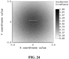
- Fig. 24 shows a photograph image illustrating simulation results of imaging when a gas leak is modelled by an object plane OP' in a DUT 50' with small refractive index changes.
- leak detection system 10' of Figs. 22 and 23 was used as described above to examine the intentional leak created in the DUT 50'. Similar to the results shown in Fig. 3 , spatial filtering clearly creates contrast variation in the image at the center of the image.
- Fig. 7 illustrates an exemplary method for detecting and evaluating leaks in a device under test, such as DUT 50 ( Fig. 6 ).
- This method 300 may be performed by a human user of a system made in accordance with the present disclosure, or may be automated through the use of a computer or controller as further described below.
- Fig. 7 shows a method of generating and evaluating a sensed image using a system, such as system 10, in accordance with the present disclosure.
- a coherent or incoherent light signal is emitted, such as by applying electrical power to a light source to generate light signal 14.
- the light signal is a laser or LED signal coming from light source 12.
- step 320 at least a portion of the light signal is passed through a collimation lens, such as lens 16, to create a collimated light signal, such as signal 18.
- step 330 at least a portion of the collimated light signal is passed through a 4F imaging telescope, such as telescope 20.
- a 4F imaging telescope such as telescope 20.
- the signal is filtered by a spatial filter, such as spatial filter 26 described above.
- system 10 is ready to be used for evaluation of a device under test (DUT), such as DUT 50 shown in Fig. 6 .
- DUT device under test
- a DUT is placed into an object plane between the collimation lens and the 4F imaging telescope, illustratively object plane OP shown in Fig. 1 .
- the DUT may be rotated, translated or otherwise reoriented to view different surfaces and areas of the DUT.
- the DUT may be moved systematically along a series of motions to establish a "grid" or other systematic series of evaluated areas, such that the entirety of the surface of interest in the DUT are subjected to leak evaluation.
- step 350 an image is generated at an image plane positioned at an output side of the 4F imaging telescope, such as image plane IP shown in Fig. 1 .
- step 360 the contrast in this sensed image may then be evaluated to determine the presence and magnitude of leaks in the DUT.
- the controller may be microprocessor-based and includes a non-transitory computer readable medium which includes processing instructions stored therein that are executable by the microprocessor of controller to evaluate the detected image to evaluate the presence and/or extent of a leak L1, L2 by assessing the presence or absence of contrast variation CV1 and/or CV2 ( Figs. 4 and 5 ).
- a non-transitory computer-readable medium, or memory may include random access memory (RAM), read-only memory (ROM), erasable programmable read-only memory (e.g., EPROM, EEPROM, or Flash memory), or any other tangible medium capable of storing information.
- the image generated by the present system may be processed by software designed to detect and evaluate contrast variation and determine the defect size and generate scores corresponding to the presence, magnitude and character of any leaks L1, L2 ( Fig. 6 ). Both conventional image processing and machine learning techniques can be used to implement this software, including using the methods described in detail below.
- Exemplary images which may be generated by systems 10 or 10' are depicted in Figs. 9 and 10 .
- spatial filtering may be applied to the raw image sensed by an imaging device (such as device 29 or 29') to more clearly show the size, location and characteristics of leaks in images sensed by, e.g., the images developed by system 10 at step 360 of Fig. 7 .
- optical leaks detected by system 10 would not be expected to present as isolated pixels in the image.
- the leaky regions, such as leaky region LR shown in Figs. 9 and 10 will instead present as a cluster of pixels that connect to the DUT 50.
- the leaky region LR will have high intensity variation in the resulting background-subtracted image ( Fig. 9 ).
- a spatial filtering software using the method disclosed in Fig. 8 can eliminate the impact of optical noise on the background-subtracted image to arrive at an optical noise filtered image, as shown in Fig. 10 .
- the present optical noise filtering allows for leaky region LR to be highlighted and easily discerned, as shown in Fig. 10 .
- the impact of optical noise ON is eliminated though the optical noise filtering software. Further details of noise filtering software and systems are further described herein.
- a method of image modification and interpretation may be used to identify and characterize leaks.
- input images are first subject to background subtraction as described herein (e.g., with reference to the image of Fig. 9 ).
- the resulting background subtracted image then undergoes optical noise filtering, with the optical noise filtering system optionally further including user-modifiable parameters which can be tuned and optimized to detect large leaks and/or small leaks in the DUT 50 as further discussed below.
- an image such as shown in Fig. 10 may be generated.
- the method may utilize image metrics measurement for specific leaky regions or types of leaky regions, if multiple. These regions can be segmented out for separate classification. For each of the leaky regions, image metrices representing the severity of each leak can be computed. Thus, within one DUT 50 ( Fig. 6 ), the spots with large leaks and the spots with small leaks can be independently located and classified.
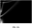
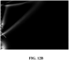
- Some of the image metrices representing the optical leaks include size of the leak in terms of number of pixels, and average pixel-intensity of the leak. Furthermore, a single leaky region can be further analyzed by splitting it into two. This would allow the software to quantify the leaky regions through image metrices such as number of leaks ( Fig. 12A ), width of leaks ( Fig. 12B ), length of leaks ( Fig. 12C ), leakage travel area ( Fig. 12D ), and various gradient-based metrics.
- Fig. 12A indicates number of leaks by placing an indicator, such as dots on the points of origination of the leak and totaling the number of indicators present in the after-analyzed image.
- Fig. 12B indicates the width of leaks by placing indicators, such as arrows, on the outer perimeter of the leakage trail and measuring the distance between indicators.
- Fig. 12C indicates length of leaks by placing indicators, such as arrows, along the entire length of the leak and measuring the length of the indicator.
- Fig. 12D indicates area of leak by drawing a line around the perimeters of the leak and calculating the area of the indicator shape.
- the optical noise filtered image can be divided into "grids" and the image metrices on each grid can be computed. Inferences based on the relative difference between the grid values is also contemplated for use in connection with the present system and method.
- a user may define a particular Region-of-Interest (ROI) in the DUT 50, as shown in Fig. 11 .
- ROI Region-of-Interest
- one or more Regions-of-Non-Interest can also be defined in the DUT 50 as shown in Fig. 11 .
- the region closer to the DUT boundary can be expected to have higher pixel intensities due to high pressure. But these cannot be inferred as leak regions since the high pressure normally associated with a leak are also present at non-leaking boundary areas. So, the boundary area may be designated as a Region-of-Non-Interest (RONI), and the contributions from such RONI can be suppressed through imaging operations designed to exclude the RONI from the overall analysis of the DUT 50.
- RONI Region-of-Non-Interest
- the leak detection and optical noise filtering software can further employ a machine learning (ML) based estimation designed to determine leak location and a volumetric leak rate in Standard Cubic Centimeters per Minute (SCCM).
- ML machine learning
- SCCM Standard Cubic Centimeters per Minute
- DL deep learning
- fps corresponds to the frames per second of the camera and SCCM i,j corresponds to the SCCM at the i th second and j th frame.
- the background subtracted images and the corresponding ground truth cubic centimeters are provided for training.
- the optical noise filtering software described herein, can also be applied on the background subtracted image prior to training.
- the features are extracted and using the ML/DL regression model, the system is trained.
- Fig. 14 in the testing phase, from the given background subtracted image, the same features are extracted and fed to the trained ML/DL regression model.
- the model predicts the cubic centimeters value for each frame.
- the disclosed ML/DL model is trained to predict the leakage on each video frame. Then the predicted values are agglomerated to compute the corresponding SCCM value at an instant of time.
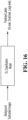
- the optical noise filtering software can also be modeled as a classification problem.
- the training phase would include the background subtracted images and the corresponding ground truth labels, such as "no leak,” "small leak” or “large leak.”
- a test DUT is provided with the designated leak characteristics, such as a "No Leak DUT,” a “Small Leak DUT” or a “Large Leak DUT” and its ground truth label is associated with its leak characteristics.
- the resulting data is developed into the output DL Classification Model.
- the optical noise filtering software can also be applied on the background subtracted image as described herein.
- the trained deep learning classification model output from the method of Fig. 15 is used as the processing model for a background subtracted image for a DUT 50.
- the image is uploaded to the DL Classification Model and a Predicted Label is output showing whether the DUT 50 is a no-leak, small-leak or large-leak device.
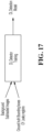
- the optical noise filtering software can also be modeled as a detection problem.
- the background subtracted images and corresponding ground truth bounding boxes of known leaky regions are provided for training.
- the optical noise filtering software can also be applied to the background subtracted image as described herein.
- the bounding boxes represent the leaky regions known to exist in the image.
- the output of the training system is the DL Detection Model.
- the trained deep learning detection model output from the method of Fig. 17 is used as the processing model for a background subtracted image for a DUT 50.
- the image is uploaded to the Detection Model and one or more Predicted Bounding Boxes is showing the leaky regions of the DUT 50.
- the optical noise filtering software could be modeled as a segmentation problem.
- the background subtracted images and corresponding ground truth binary mask images e.g., as shown in Figs. 9 and 10
- customized optical noise filtering can also be applied on the background subtracted image, such as the filtering shown and described in connection with the method of Fig. 11 .
- the binary mask images represent the known leaky regions in the image as white pixels and the other regions as black pixels.
- the output of this DL Segmentation Training is the DL Segmentation Model.
- the trained Segmentation Model output from the method of Fig. 19 is used as the processing model for an image from a DUT 50.
- Predicted Leaky regions of the DUT 50 are output, with associated exact (i.e., binary) boundaries are obtained as the output of the DL Segmentation Model.
- the leakage width, leakage length and the leakage travel area can be computed as described above with respect to Figs. 12A-12D , for example.
- DUT 50 may be a mobile phone, tablet, or other handheld display device, and system 10 is used to evaluate a hermetically sealed casing around the mobile phone or tablet.
- Fig. 6 schematically illustrates a portion of a mobile phone.
- the mobile phone is configured in a convenient package suitable for handling by human hands.
- a tablet may be configured similarly to the phone, except with larger overall dimensions.
- an exemplary mobile phone 400 includes a back cover 410.
- a bottom shell 420 is interfaced with a face shell 430 to protect the circuit board 425 that is configured to provide functionality to the mobile phone 400.
- the bottom shell 420 is configured to support a battery 415, and is further configured to interface with the back cover 410.
- the face shell 430 is configured to interface with and support a display module 440.
- the display module 440 includes a display layer 470 and cover glass/touch panel 450a.
- the cover glass/touch panel 450a is configured as a transparent material or transparent optical material.
- DUT 50 may be any device that is configured to be hermetically sealed, such that an understanding of the presence and character of leaks can be used to determine whether the hermetically sealed configuration has been achieved in fact with any given device sample.
- Devices configured to be hermetically sealed may include mobile phones and tablets, ad discussed above, as well as other devices such as smart watches and ear phones, or any other types of electrical components that require tight sealing.
- the display module 440 includes a display layer 470, such as a liquid crystal display (LCD), a circular polarizer 460, and optically transparent cover glass/touch panel 450a.
- the circular polarizer 460 may be integrated within the display layer 470 as is shown by the dotted outline surrounding both the display layer 470 and circular polarizer 460.
- the display layer 470 is configured to provide a visual interface with a corresponding user, such as by displaying images that are viewable by the user.
- the display layer 470 may include one or more additional layers, as required or desired for a particular application.
- Various technologies are used to build the display layer 470 typically configured as pixels providing colored light that are viewable by a user.
- the cover glass/touch panel 450a is located adjacent to the display layer 470 or the circular polarizer 460 that is associated with the display layer 470.
- Cover glass/touch panel 450a is configured as a user interface, wherein the user may interact with the mobile phone 400 and/or provide input control through touching the glass or panel 450a using a stylus or one or more fingers.
- display module 440 and/or transparent optical material 450a are contemplated, such as any mobile devices with display screens, television screens, computer monitors, tablet devices, integrated display screens (e.g., integrated into dash of vehicle, desk surface, panel, etc.), portable communication devices, etc.
- bottom shell 420, face shell 430, back cover 410, and/or cover glass 450a may cooperate to form a hermetically sealed interior space to contain and protect internal components, including battery 415, circuit board 425, polarizer 460 and display layer 470, for example.
- Embodiments of the present disclosure, including leak detection system 10 described in detail above, are configured to detect and/or measure any leaks from this hermetically sealed interior space.
Landscapes
- Physics & Mathematics (AREA)
- Engineering & Computer Science (AREA)
- General Physics & Mathematics (AREA)
- Theoretical Computer Science (AREA)
- Computer Vision & Pattern Recognition (AREA)
- Optics & Photonics (AREA)
- Signal Processing (AREA)
- Life Sciences & Earth Sciences (AREA)
- Data Mining & Analysis (AREA)
- Astronomy & Astrophysics (AREA)
- Biochemistry (AREA)
- Immunology (AREA)
- Multimedia (AREA)
- Pathology (AREA)
- General Health & Medical Sciences (AREA)
- Analytical Chemistry (AREA)
- Chemical & Material Sciences (AREA)
- Health & Medical Sciences (AREA)
- Bioinformatics & Cheminformatics (AREA)
- Quality & Reliability (AREA)
- Geometry (AREA)
- Artificial Intelligence (AREA)
- Bioinformatics & Computational Biology (AREA)
- Evolutionary Computation (AREA)
- Evolutionary Biology (AREA)
- General Engineering & Computer Science (AREA)
- Fluid Mechanics (AREA)
- Examining Or Testing Airtightness (AREA)
- Investigating Or Analysing Materials By Optical Means (AREA)
Claims (16)
- Un système d'imagerie comprenantune source de lumière ponctuelle (12) configurée pour émettre un signal lumineux (14),une lentille de collimation (16) positionnée pour recevoir le signal lumineux (14), la lentille de collimation (16) étant configurée pour émettre un signal lumineux collimaté (18),un télescope d'imagerie (20) positionné pour recevoir le signal lumineux collimaté (18),un filtre spatial (26) positionné sur un plan du télescope d'imagerie (20), le filtre spatial (26) étant configuré pour laisser passer un signal lumineux filtré (28),un capteur d'image (29) positionné du côté de la sortie du télescope d'imagerie (20) de manière à ce que le capteur d'image (29) soit positionné pour recevoir le signal lumineux filtré (28),un dispositif à tester (50) etune source de gaz sous pression configurée pour pressuriser un volume intérieur du dispositif à tester (50), le système d'imagerie (20) étant configuré pour détecter une fuite du gaz sous pression du dispositif à tester (50), le système d'imagerie (20) étant configuré pour fournir une détection de fuite optique pour le dispositif à tester (50),caractérisé en ce quele télescope d'imagerie est un télescope d'imagerie 4F (20),le dispositif à tester (50) est positionné sur un plan objet (OP) entre la lentille de collimation (16) et le télescope d'imagerie 4F (20), etle filtre spatial (26) est positionné sur un plan de Fourier du télescope d'imagerie 4F (20).
- Le système d'imagerie selon la revendication 1, où le gaz a un indice de réfraction différent de celui de l'air ambiant.
- Le système d'imagerie selon la revendication 1, où le dispositif à tester (50) est configuré comme un dispositif hermétiquement scellé.
- Le système d'imagerie selon la revendication 1, où le signal lumineux est un signal lumineux incohérent (14).
- Le système d'imagerie selon la revendication 4, où le signal lumineux incohérent (14) est émis par une diode luminescente.
- Le système d'imagerie selon la revendication 1, où le signal lumineux (14) est un signal lumineux cohérent.
- Le système d'imagerie selon la revendication 6, où le signal lumineux cohérent est émis par un laser.
- Le système d'imagerie selon la revendication 1, où le capteur d'image (29) est un dispositif d'imagerie connecté de manière opérative à une commande, la commande étant programmée avec des instructions de traitement pour évaluer une image détectée afin de déterminer la présence d'une fuite en analysant la présence ou l'absence de variation de contraste dans l'image détectée.
- Un procédé pour évaluer des fuites dans un dispositif, le procédé comprenantémettre un signal lumineux (14),modifier le signal lumineux (14) pour créer un signal lumineux collimaté (18),filtrer le signal lumineux (14) pour créer un signal lumineux filtré (28),détecter le signal lumineux filtré (28) pour créer une image détectée,diriger un gaz sous pression dans un volume intérieur d'un dispositif à tester (50),évaluer le contraste dans l'image détectée eten se basant sur l'étape d'évaluation du contraste, déterminer si le gaz sous pression fuit du volume intérieur du dispositif à tester, caractérisé en ce que le procédé comprend en outre de placer un dispositif à tester (50) sur un plan objet (OP) le long du signal lumineux collimaté (18) de manière à ce qu'une image du dispositif à tester (50) apparaisse dans l'image détectée, et de filtrer le signal lumineux avec un filtre spatial (26) positionné sur un plan de Fourier d'un télescope d'imagerie 4F (20).
- Le procédé selon la revendication 9, où le gaz sous pression a un indice de réfraction différent de celui de l'air.
- Le procédé selon la revendication 10, comprenant en outre la détermination de la magnitude et du caractère de la fuite dans le dispositif à tester (50) en se basant sur le contraste dans l'image détectée.
- Le procédé selon la revendication 9, où le dispositif à tester (50) est configuré comme un dispositif hermétiquement scellé.
- Le procédé selon la revendication 9, où l'étape d'émission du signal lumineux comprend l'émission d'un signal lumineux incohérent (14).
- Le procédé selon la revendication 9, où l'étape d'émission du signal lumineux (14) comprend l'émission d'un signal lumineux cohérent.
- Le procédé selon la revendication 9, où l'étape de détection du signal lumineux filtré (28) pour créer l'image détectée comprend la capture de l'image détectée avec un capteur d'image (29).
- Le procédé selon la revendication 15, où l'étape d'évaluation du contraste dans l'image détectée est effectuée par une commande connectée de manière opérative au capteur d'image (29).
Applications Claiming Priority (1)
| Application Number | Priority Date | Filing Date | Title |
|---|---|---|---|
| US202062958764P | 2020-01-09 | 2020-01-09 |
Publications (4)
| Publication Number | Publication Date |
|---|---|
| EP3848691A2 EP3848691A2 (fr) | 2021-07-14 |
| EP3848691A3 EP3848691A3 (fr) | 2021-10-06 |
| EP3848691B1 true EP3848691B1 (fr) | 2024-10-09 |
| EP3848691C0 EP3848691C0 (fr) | 2024-10-09 |
Family
ID=74141331
Family Applications (1)
| Application Number | Title | Priority Date | Filing Date |
|---|---|---|---|
| EP21150082.2A Active EP3848691B1 (fr) | 2020-01-09 | 2021-01-04 | Système d'imagerie pour détection de fuites |
Country Status (6)
| Country | Link |
|---|---|
| US (1) | US12196944B2 (fr) |
| EP (1) | EP3848691B1 (fr) |
| JP (1) | JP7362987B2 (fr) |
| KR (1) | KR20210090116A (fr) |
| CN (1) | CN113108996A (fr) |
| TW (1) | TWI833060B (fr) |
Families Citing this family (30)
| Publication number | Priority date | Publication date | Assignee | Title |
|---|---|---|---|---|
| US11607654B2 (en) | 2019-12-30 | 2023-03-21 | Marathon Petroleum Company Lp | Methods and systems for in-line mixing of hydrocarbon liquids |
| CA3104319C (fr) | 2019-12-30 | 2023-01-24 | Marathon Petroleum Company Lp | Procedes et systemes de gestion du refoulement dans le melange en conduite de liquides d'hydrocarbures |
| US11655940B2 (en) | 2021-03-16 | 2023-05-23 | Marathon Petroleum Company Lp | Systems and methods for transporting fuel and carbon dioxide in a dual fluid vessel |
| US11578638B2 (en) | 2021-03-16 | 2023-02-14 | Marathon Petroleum Company Lp | Scalable greenhouse gas capture systems and methods |
| US12012883B2 (en) | 2021-03-16 | 2024-06-18 | Marathon Petroleum Company Lp | Systems and methods for backhaul transportation of liquefied gas and CO2 using liquefied gas carriers |
| US11578836B2 (en) | 2021-03-16 | 2023-02-14 | Marathon Petroleum Company Lp | Scalable greenhouse gas capture systems and methods |
| US12129559B2 (en) | 2021-08-26 | 2024-10-29 | Marathon Petroleum Company Lp | Test station assemblies for monitoring cathodic protection of structures and related methods |
| US11447877B1 (en) | 2021-08-26 | 2022-09-20 | Marathon Petroleum Company Lp | Assemblies and methods for monitoring cathodic protection of structures |
| US12180597B2 (en) | 2021-08-26 | 2024-12-31 | Marathon Petroleum Company Lp | Test station assemblies for monitoring cathodic protection of structures and related methods |
| US12043905B2 (en) | 2021-08-26 | 2024-07-23 | Marathon Petroleum Company Lp | Electrode watering assemblies and methods for maintaining cathodic monitoring of structures |
| CN115308208A (zh) * | 2021-12-09 | 2022-11-08 | 苏州大学 | 一种气体泄漏检测系统及方法 |
| CN114815281B (zh) * | 2022-04-12 | 2023-03-24 | 哈尔滨工程大学 | 一种高精度纹影系统光路调节装置及其使用方法 |
| US11686070B1 (en) | 2022-05-04 | 2023-06-27 | Marathon Petroleum Company Lp | Systems, methods, and controllers to enhance heavy equipment warning |
| US20230400714A1 (en) * | 2022-06-08 | 2023-12-14 | Johnson & Johnson Vision Care, Inc. | Methods for quality control of contact lenses |
| CN115290267A (zh) * | 2022-07-11 | 2022-11-04 | 奇力士(武汉)智慧水务科技有限公司 | 一种静音防淹二次供水设备的密封测试方法及装置 |
| CN116202957B (zh) * | 2022-09-07 | 2025-10-17 | 核工业西南物理研究院 | 一种测量混合透明介质的快扫多色纹影系统及其测量方法 |
| CN115752948B (zh) * | 2022-12-01 | 2025-08-01 | 重庆赛迪奇智人工智能科技有限公司 | 一种设备内水路密封性检测方法及装置 |
| US12012082B1 (en) | 2022-12-30 | 2024-06-18 | Marathon Petroleum Company Lp | Systems and methods for a hydraulic vent interlock |
| CN116008232B (zh) * | 2023-01-06 | 2026-04-10 | 大连理工大学 | 用于观测激波管内涡旋结构的单镜共轴纹影成像方法 |
| CN116222925A (zh) * | 2023-01-09 | 2023-06-06 | 安徽道纪量子科技有限公司 | 一种基于量子成像油气折射率的油气泄露探测系统及方法 |
| JP7792359B2 (ja) * | 2023-01-23 | 2025-12-25 | 国立大学法人 新潟大学 | 3次元画像解析による漏洩現象の同定方法及び同定システム |
| US12043361B1 (en) | 2023-02-18 | 2024-07-23 | Marathon Petroleum Company Lp | Exhaust handling systems for marine vessels and related methods |
| US12006014B1 (en) | 2023-02-18 | 2024-06-11 | Marathon Petroleum Company Lp | Exhaust vent hoods for marine vessels and related methods |
| US12602758B1 (en) * | 2023-03-17 | 2026-04-14 | Ut-Battelle, Llc | Building leakage detector using reference-free background oriented schlieren photography |
| CN117782312A (zh) * | 2023-04-10 | 2024-03-29 | 立讯智造(浙江)有限公司 | 屏下光传感器的测试方法、系统、电子设备、存储介质和程序产品 |
| CN116878748A (zh) * | 2023-06-06 | 2023-10-13 | 浙江省计量科学研究院 | 一种激光与图像融合的智能气体泄漏定位方法及装置 |
| US12297965B2 (en) | 2023-08-09 | 2025-05-13 | Marathon Petroleum Company Lp | Systems and methods for mixing hydrogen with natural gas |
| US12597151B2 (en) | 2023-09-18 | 2026-04-07 | Marathon Petroleum Company Lp | Systems and methods to determine vegetation encroachment along a right-of-way |
| CN117635610B (zh) * | 2024-01-25 | 2024-04-09 | 青岛正大正电力环保设备有限公司 | 一种液压张紧机构油管漏油视觉检测方法 |
| CN118424587A (zh) * | 2024-05-07 | 2024-08-02 | 深圳市希立仪器设备有限公司 | 一种可视化气密性漏点侦测方法 |
Family Cites Families (55)
| Publication number | Priority date | Publication date | Assignee | Title |
|---|---|---|---|---|
| JPS53134776A (en) * | 1977-04-28 | 1978-11-24 | Kuraray Co Ltd | Method and apparatus for detecting leak portions in hollow fiber modules employed for liquid treatments |
| JPS63273031A (ja) * | 1987-04-30 | 1988-11-10 | Osaka Hoki Seisakusho:Kk | 密封容器等の不良検査方法 |
| JPH02138845A (ja) | 1987-09-08 | 1990-05-28 | Erumetsukusu:Kk | 密封容器等からの漏洩検査方法 |
| FR2643149B1 (fr) | 1989-02-16 | 1994-10-21 | Elmetherm | Procede et dispositif de controle de l'etancheite de produits enveloppants tels que des gants en latex |
| JPH02242103A (ja) | 1989-03-06 | 1990-09-26 | Rotorex Opt Ltd | 多種の用途に独立かつ選択的に操作可能な光学的検査装置 |
| JPH0351737A (ja) | 1989-07-19 | 1991-03-06 | Erumetsukusu:Kk | 高感度シュリーレン装置 |
| US5309222A (en) | 1991-07-16 | 1994-05-03 | Mitsubishi Denki Kabushiki Kaisha | Surface undulation inspection apparatus |
| JP3237309B2 (ja) | 1992-06-17 | 2001-12-10 | キヤノン株式会社 | システムエラー測定方法及びそれを用いた形状測定装置 |
| JPH063625A (ja) | 1992-06-23 | 1994-01-14 | Kazumi Haga | 検査装置 |
| JPH06221955A (ja) | 1993-01-22 | 1994-08-12 | Katsuya Yamada | 容器の欠陥検査方法 |
| US6181416B1 (en) | 1998-04-14 | 2001-01-30 | Optometrix, Inc. | Schlieren method for imaging semiconductor device properties |
| GB9903638D0 (en) | 1999-02-17 | 1999-04-07 | European Community | A measurement method and measurement apparatus |
| DE60130968T2 (de) | 2000-01-10 | 2008-07-10 | Massachusetts Institute of Technology Inc., Cambridge | Apparat und verfahren zur oberflächenkonturmessung |
| US6744522B2 (en) | 2001-02-01 | 2004-06-01 | Zygo Corporation | Interferometer for measuring the thickness profile of thin transparent substrates |
| JP4921644B2 (ja) | 2001-02-27 | 2012-04-25 | オリンパス株式会社 | 波面測定装置および波面測定方法 |
| JP2002340538A (ja) | 2001-05-14 | 2002-11-27 | Matsushita Electric Ind Co Ltd | 薄板材の平坦度測定装置および方法 |
| US6812846B2 (en) * | 2001-09-28 | 2004-11-02 | Koninklijke Philips Electronics N.V. | Spill detector based on machine-imaging |
| AU2002347227A1 (en) * | 2001-12-05 | 2003-06-17 | Universite Libre De Bruxelles | Apparatus and process for characterising samples |
| US6847458B2 (en) | 2003-03-20 | 2005-01-25 | Phase Shift Technology, Inc. | Method and apparatus for measuring the shape and thickness variation of polished opaque plates |
| KR100955486B1 (ko) | 2004-01-30 | 2010-04-30 | 삼성전자주식회사 | 디스플레이 패널의 검사장치 및 검사방법 |
| JP2005315649A (ja) | 2004-04-27 | 2005-11-10 | Sumitomo Heavy Ind Ltd | 検出装置及びステージ装置 |
| US7268887B2 (en) | 2004-12-23 | 2007-09-11 | Corning Incorporated | Overlapping common-path interferometers for two-sided measurement |
| JP4625716B2 (ja) | 2005-05-23 | 2011-02-02 | 株式会社日立ハイテクノロジーズ | 欠陥検査装置及び欠陥検査方法 |
| US8567980B2 (en) | 2006-06-30 | 2013-10-29 | Todd Eisenberg | Incapacitating high intensity incoherent light beam |
| CN200944170Y (zh) | 2006-07-20 | 2007-09-05 | 维钛光电科技股份有限公司 | 圆偏光型触控液晶模组 |
| JP2008076962A (ja) | 2006-09-25 | 2008-04-03 | Okano Denki Kk | 光学検査装置 |
| AR064643A1 (es) | 2006-12-21 | 2009-04-15 | Univ Arizona | Cubeta para lente oftalmica |
| US7570366B2 (en) | 2007-02-21 | 2009-08-04 | Corning Incorporated | Apparatus for measuring defects in a glass sheet |
| CN100552376C (zh) | 2007-04-13 | 2009-10-21 | 南京师范大学 | 光学干涉测量中分光、成像及同步移相的方法和装置 |
| KR101338995B1 (ko) | 2008-06-10 | 2013-12-09 | 엘지디스플레이 주식회사 | 액정표시장치 |
| US7796275B2 (en) | 2008-11-12 | 2010-09-14 | Zygo Corporation | Phase-shifting interferometry in the presence of vibration using phase bias |
| JP5301405B2 (ja) | 2009-09-30 | 2013-09-25 | 株式会社日立ハイテクノロジーズ | 表面欠陥検査装置 |
| US8269157B2 (en) | 2009-10-23 | 2012-09-18 | Academia Sinica | Optical imaging system |
| JP2012021781A (ja) | 2010-07-12 | 2012-02-02 | Asahi Glass Co Ltd | 表面形状の評価方法および評価装置 |
| US8982355B2 (en) | 2010-12-09 | 2015-03-17 | The United States Of America As Represented By The Administrator Of The National Aeronautics And Space Administration | Smart optical material characterization system and method |
| JP2012208181A (ja) | 2011-03-29 | 2012-10-25 | Seiko Epson Corp | コントラスト検査装置 |
| US9212901B2 (en) | 2013-04-17 | 2015-12-15 | Corning Incorporated | Apparatus and methods for performing wavefront-based and profile-based measurements of an aspheric surface |
| US9726617B2 (en) | 2013-06-04 | 2017-08-08 | Kla-Tencor Corporation | Apparatus and methods for finding a best aperture and mode to enhance defect detection |
| JP6273703B2 (ja) | 2013-07-17 | 2018-02-07 | 東洋製罐グループホールディングス株式会社 | 被検査物の検査方法及びその検査装置 |
| CN203432964U (zh) | 2013-09-06 | 2014-02-12 | 中国科学技术大学 | 一种高压可燃性气体泄漏自燃及激波诱导点火的试验装置 |
| CN103712573B (zh) | 2013-12-27 | 2016-04-20 | 华南师范大学 | 双通道干涉测量中面阵图像传感器的空间匹配校正方法 |
| WO2015105980A1 (fr) | 2014-01-09 | 2015-07-16 | Zygo Corporation | Mesurer la topographie de surfaces asphériques et autres surfaces non plates |
| CN103884486B (zh) | 2014-02-27 | 2017-01-11 | 中国科学院力学研究所 | 纹影测量成像系统及方法 |
| US10455137B2 (en) | 2014-07-28 | 2019-10-22 | Orbotech Ltd. | Auto-focus system |
| CN104155071A (zh) | 2014-08-12 | 2014-11-19 | 中国科学院合肥物质科学研究院 | 一种基于背景纹影技术的气体泄漏监测装置与方法 |
| CN105468185A (zh) | 2014-09-12 | 2016-04-06 | 南昌欧菲光学技术有限公司 | 一种触控显示屏及移动终端 |
| TWI596448B (zh) | 2016-05-12 | 2017-08-21 | 國立中山大學 | 平坦化干涉微影裝置 |
| JP2018031716A (ja) | 2016-08-26 | 2018-03-01 | 東洋製罐グループホールディングス株式会社 | 欠陥検査装置及び欠陥検査方法 |
| WO2018094277A1 (fr) | 2016-11-18 | 2018-05-24 | The Arizona Board Of Regents On Behalf Of The University Of Arizona | Déflectométrie de cartographie de phase instantanée |
| JP2019070751A (ja) * | 2017-10-10 | 2019-05-09 | オリンパス株式会社 | 観察装置および焦点調節方法 |
| JP7000197B2 (ja) * | 2018-02-16 | 2022-01-19 | 浜松ホトニクス株式会社 | 濃度測定方法及び濃度測定装置 |
| CN113330346B (zh) * | 2018-06-13 | 2023-06-23 | 奇跃公司 | 光学器件边缘密封剂的光泄露检测 |
| US11143503B2 (en) | 2018-08-07 | 2021-10-12 | Kimball Electronics Indiana, Inc. | Interferometric waviness detection systems |
| CN109141835B (zh) | 2018-09-28 | 2019-12-24 | 中国兵器工业标准化研究所 | 投影及纹影二合一光学测试系统 |
| US20210042909A1 (en) | 2019-08-07 | 2021-02-11 | Kimball Electronics Indiana, Inc. | Imaging system for surface inspection |
-
2020
- 2020-12-28 US US17/134,918 patent/US12196944B2/en active Active
-
2021
- 2021-01-04 EP EP21150082.2A patent/EP3848691B1/fr active Active
- 2021-01-06 TW TW110100385A patent/TWI833060B/zh active
- 2021-01-08 CN CN202110023466.3A patent/CN113108996A/zh active Pending
- 2021-01-08 JP JP2021001820A patent/JP7362987B2/ja active Active
- 2021-01-11 KR KR1020210003012A patent/KR20210090116A/ko active Pending
Also Published As
| Publication number | Publication date |
|---|---|
| US20210215925A1 (en) | 2021-07-15 |
| TW202134620A (zh) | 2021-09-16 |
| KR20210090116A (ko) | 2021-07-19 |
| EP3848691A2 (fr) | 2021-07-14 |
| JP2021110752A (ja) | 2021-08-02 |
| EP3848691A3 (fr) | 2021-10-06 |
| TWI833060B (zh) | 2024-02-21 |
| CN113108996A (zh) | 2021-07-13 |
| US12196944B2 (en) | 2025-01-14 |
| EP3848691C0 (fr) | 2024-10-09 |
| JP7362987B2 (ja) | 2023-10-18 |
Similar Documents
| Publication | Publication Date | Title |
|---|---|---|
| EP3848691B1 (fr) | Système d'imagerie pour détection de fuites | |
| US4772789A (en) | Leak imaging using differential absorption | |
| US10809148B2 (en) | Combined gas leakage detection and quantification | |
| US5082366A (en) | Apparatus and method for detecting leaks in packages | |
| US10942086B2 (en) | Light leakage detection in edge sealants of optical devices | |
| CA2568260A1 (fr) | Systeme d'inspection de materiau transparent | |
| JP2019095431A (ja) | トレーサガスによる被検査物の密封性検査用漏洩検知モジュール、および漏洩検知方法 | |
| CN116735158A (zh) | 透镜图像产生系统及屈光能力和厚度确定与缺陷检测方法 | |
| JP4371157B2 (ja) | 液量測定装置及び液量測定方法 | |
| KR102951633B1 (ko) | 표면 검사를 위한 이미징 시스템 | |
| KR20210018141A (ko) | 표면 검사를 위한 이미징 시스템 | |
| CN114486128B (zh) | 融合超声波和被动式红外成像的气体泄漏检测装置及方法 | |
| CN103424412B (zh) | 基于红外热成像的复合气瓶检测系统 | |
| CN217303862U (zh) | 油封轮廓检测设备 | |
| HK40056895A (en) | Imaging system for leak detection | |
| JP2004347478A (ja) | 漏洩検査方法および漏洩検査装置 | |
| WO2021203651A1 (fr) | Appareil d'inspection de bord latéral de coque et procédé d'inspection de bord latéral de coque pour produit électronique | |
| KR100552233B1 (ko) | Ccd카메라와 열영상의 매핑을 이용한 열영상 관측화면의 방사율 보정기법 | |
| CN117629534A (zh) | 气体泄漏检测方法、装置及气体泄漏样本采集系统 | |
| JP2015021778A (ja) | 被検査物の検査方法及びその検査装置 | |
| Kmec et al. | Optical noncontact method to detect amplitude defects of polymeric objects | |
| Kim et al. | Imaging system for leak detection using collimated white/color LED light | |
| JPH06235676A (ja) | 密封容器の圧洩れ検査装置 | |
| CN121323877A (zh) | 飞机整体驱动发电机静态测试方法及系统、介质、设备 | |
| CN121933207A (zh) | 气体泄漏检测装置、气体泄漏检测方法、设备及介质 |
Legal Events
| Date | Code | Title | Description |
|---|---|---|---|
| PUAI | Public reference made under article 153(3) epc to a published international application that has entered the european phase |
Free format text: ORIGINAL CODE: 0009012 |
|
| STAA | Information on the status of an ep patent application or granted ep patent |
Free format text: STATUS: THE APPLICATION HAS BEEN PUBLISHED |
|
| AK | Designated contracting states |
Kind code of ref document: A2 Designated state(s): AL AT BE BG CH CY CZ DE DK EE ES FI FR GB GR HR HU IE IS IT LI LT LU LV MC MK MT NL NO PL PT RO RS SE SI SK SM TR |
|
| PUAL | Search report despatched |
Free format text: ORIGINAL CODE: 0009013 |
|
| AK | Designated contracting states |
Kind code of ref document: A3 Designated state(s): AL AT BE BG CH CY CZ DE DK EE ES FI FR GB GR HR HU IE IS IT LI LT LU LV MC MK MT NL NO PL PT RO RS SE SI SK SM TR |
|
| RIC1 | Information provided on ipc code assigned before grant |
Ipc: G01M 3/22 20060101ALI20210827BHEP Ipc: G01M 9/06 20060101ALI20210827BHEP Ipc: G01M 3/38 20060101AFI20210827BHEP |
|
| STAA | Information on the status of an ep patent application or granted ep patent |
Free format text: STATUS: REQUEST FOR EXAMINATION WAS MADE |
|
| REG | Reference to a national code |
Ref country code: HK Ref legal event code: DE Ref document number: 40056895 Country of ref document: HK |
|
| 17P | Request for examination filed |
Effective date: 20220321 |
|
| RBV | Designated contracting states (corrected) |
Designated state(s): AL AT BE BG CH CY CZ DE DK EE ES FI FR GB GR HR HU IE IS IT LI LT LU LV MC MK MT NL NO PL PT RO RS SE SI SK SM TR |
|
| STAA | Information on the status of an ep patent application or granted ep patent |
Free format text: STATUS: EXAMINATION IS IN PROGRESS |
|
| 17Q | First examination report despatched |
Effective date: 20240102 |
|
| GRAP | Despatch of communication of intention to grant a patent |
Free format text: ORIGINAL CODE: EPIDOSNIGR1 |
|
| STAA | Information on the status of an ep patent application or granted ep patent |
Free format text: STATUS: GRANT OF PATENT IS INTENDED |
|
| RIC1 | Information provided on ipc code assigned before grant |
Ipc: G02B 27/54 20060101ALI20240527BHEP Ipc: G01M 3/22 20060101ALI20240527BHEP Ipc: G01M 9/06 20060101ALI20240527BHEP Ipc: G01M 3/38 20060101AFI20240527BHEP |
|
| INTG | Intention to grant announced |
Effective date: 20240617 |
|
| GRAS | Grant fee paid |
Free format text: ORIGINAL CODE: EPIDOSNIGR3 |
|
| GRAA | (expected) grant |
Free format text: ORIGINAL CODE: 0009210 |
|
| STAA | Information on the status of an ep patent application or granted ep patent |
Free format text: STATUS: THE PATENT HAS BEEN GRANTED |
|
| AK | Designated contracting states |
Kind code of ref document: B1 Designated state(s): AL AT BE BG CH CY CZ DE DK EE ES FI FR GB GR HR HU IE IS IT LI LT LU LV MC MK MT NL NO PL PT RO RS SE SI SK SM TR |
|
| REG | Reference to a national code |
Ref country code: CH Ref legal event code: EP |
|
| REG | Reference to a national code |
Ref country code: DE Ref legal event code: R096 Ref document number: 602021019747 Country of ref document: DE |
|
| REG | Reference to a national code |
Ref country code: IE Ref legal event code: FG4D |
|
| U01 | Request for unitary effect filed |
Effective date: 20241107 |
|
| U07 | Unitary effect registered |
Designated state(s): AT BE BG DE DK EE FI FR IT LT LU LV MT NL PT RO SE SI Effective date: 20241114 |
|
| U20 | Renewal fee for the european patent with unitary effect paid |
Year of fee payment: 5 Effective date: 20250107 |
|
| PG25 | Lapsed in a contracting state [announced via postgrant information from national office to epo] |
Ref country code: HR Free format text: LAPSE BECAUSE OF FAILURE TO SUBMIT A TRANSLATION OF THE DESCRIPTION OR TO PAY THE FEE WITHIN THE PRESCRIBED TIME-LIMIT Effective date: 20241009 Ref country code: IS Free format text: LAPSE BECAUSE OF FAILURE TO SUBMIT A TRANSLATION OF THE DESCRIPTION OR TO PAY THE FEE WITHIN THE PRESCRIBED TIME-LIMIT Effective date: 20250209 |
|
| PG25 | Lapsed in a contracting state [announced via postgrant information from national office to epo] |
Ref country code: ES Free format text: LAPSE BECAUSE OF FAILURE TO SUBMIT A TRANSLATION OF THE DESCRIPTION OR TO PAY THE FEE WITHIN THE PRESCRIBED TIME-LIMIT Effective date: 20241009 |
|
| PG25 | Lapsed in a contracting state [announced via postgrant information from national office to epo] |
Ref country code: NO Free format text: LAPSE BECAUSE OF FAILURE TO SUBMIT A TRANSLATION OF THE DESCRIPTION OR TO PAY THE FEE WITHIN THE PRESCRIBED TIME-LIMIT Effective date: 20250109 |
|
| PG25 | Lapsed in a contracting state [announced via postgrant information from national office to epo] |
Ref country code: GR Free format text: LAPSE BECAUSE OF FAILURE TO SUBMIT A TRANSLATION OF THE DESCRIPTION OR TO PAY THE FEE WITHIN THE PRESCRIBED TIME-LIMIT Effective date: 20250110 |
|
| PG25 | Lapsed in a contracting state [announced via postgrant information from national office to epo] |
Ref country code: PL Free format text: LAPSE BECAUSE OF FAILURE TO SUBMIT A TRANSLATION OF THE DESCRIPTION OR TO PAY THE FEE WITHIN THE PRESCRIBED TIME-LIMIT Effective date: 20241009 |
|
| PG25 | Lapsed in a contracting state [announced via postgrant information from national office to epo] |
Ref country code: RS Free format text: LAPSE BECAUSE OF FAILURE TO SUBMIT A TRANSLATION OF THE DESCRIPTION OR TO PAY THE FEE WITHIN THE PRESCRIBED TIME-LIMIT Effective date: 20250109 |
|
| PG25 | Lapsed in a contracting state [announced via postgrant information from national office to epo] |
Ref country code: SM Free format text: LAPSE BECAUSE OF FAILURE TO SUBMIT A TRANSLATION OF THE DESCRIPTION OR TO PAY THE FEE WITHIN THE PRESCRIBED TIME-LIMIT Effective date: 20241009 |
|
| PG25 | Lapsed in a contracting state [announced via postgrant information from national office to epo] |
Ref country code: SK Free format text: LAPSE BECAUSE OF FAILURE TO SUBMIT A TRANSLATION OF THE DESCRIPTION OR TO PAY THE FEE WITHIN THE PRESCRIBED TIME-LIMIT Effective date: 20241009 |
|
| PG25 | Lapsed in a contracting state [announced via postgrant information from national office to epo] |
Ref country code: CZ Free format text: LAPSE BECAUSE OF FAILURE TO SUBMIT A TRANSLATION OF THE DESCRIPTION OR TO PAY THE FEE WITHIN THE PRESCRIBED TIME-LIMIT Effective date: 20241009 |
|
| PLBE | No opposition filed within time limit |
Free format text: ORIGINAL CODE: 0009261 |
|
| STAA | Information on the status of an ep patent application or granted ep patent |
Free format text: STATUS: NO OPPOSITION FILED WITHIN TIME LIMIT |
|
| REG | Reference to a national code |
Ref country code: CH Ref legal event code: PL |
|
| PG25 | Lapsed in a contracting state [announced via postgrant information from national office to epo] |
Ref country code: MC Free format text: LAPSE BECAUSE OF FAILURE TO SUBMIT A TRANSLATION OF THE DESCRIPTION OR TO PAY THE FEE WITHIN THE PRESCRIBED TIME-LIMIT Effective date: 20241009 |
|
| 26N | No opposition filed |
Effective date: 20250710 |
|
| GBPC | Gb: european patent ceased through non-payment of renewal fee |
Effective date: 20250109 |
|
| PG25 | Lapsed in a contracting state [announced via postgrant information from national office to epo] |
Ref country code: GB Free format text: LAPSE BECAUSE OF NON-PAYMENT OF DUE FEES Effective date: 20250109 |
|
| PG25 | Lapsed in a contracting state [announced via postgrant information from national office to epo] |
Ref country code: CH Free format text: LAPSE BECAUSE OF NON-PAYMENT OF DUE FEES Effective date: 20250131 |
|
| U20 | Renewal fee for the european patent with unitary effect paid |
Year of fee payment: 6 Effective date: 20251205 |
|
| PG25 | Lapsed in a contracting state [announced via postgrant information from national office to epo] |
Ref country code: IE Free format text: LAPSE BECAUSE OF NON-PAYMENT OF DUE FEES Effective date: 20250104 |
|
| U1N | Appointed representative for the unitary patent procedure changed after the registration of the unitary effect |
Representative=s name: MAUCHER JENKINSPATENT- UND RECHTSANWAELTE; DE |