EP3850175B1 - Einrichtung zur justierung eines türantriebs - Google Patents
Einrichtung zur justierung eines türantriebs Download PDFInfo
- Publication number
- EP3850175B1 EP3850175B1 EP19778856.5A EP19778856A EP3850175B1 EP 3850175 B1 EP3850175 B1 EP 3850175B1 EP 19778856 A EP19778856 A EP 19778856A EP 3850175 B1 EP3850175 B1 EP 3850175B1
- Authority
- EP
- European Patent Office
- Prior art keywords
- door drive
- car body
- adjusting
- side console
- door
- Prior art date
- Legal status (The legal status is an assumption and is not a legal conclusion. Google has not performed a legal analysis and makes no representation as to the accuracy of the status listed.)
- Active
Links
Images


Classifications
-
- B—PERFORMING OPERATIONS; TRANSPORTING
- B61—RAILWAYS
- B61D—BODY DETAILS OR KINDS OF RAILWAY VEHICLES
- B61D19/00—Door arrangements specially adapted for rail vehicles
-
- E—FIXED CONSTRUCTIONS
- E05—LOCKS; KEYS; WINDOW OR DOOR FITTINGS; SAFES
- E05F—DEVICES FOR MOVING WINGS INTO OPEN OR CLOSED POSITION; CHECKS FOR WINGS; WING FITTINGS NOT OTHERWISE PROVIDED FOR, CONCERNED WITH THE FUNCTIONING OF THE WING
- E05F15/00—Power-operated mechanisms for wings
- E05F15/60—Power-operated mechanisms for wings using electrical actuators
- E05F15/603—Power-operated mechanisms for wings using electrical actuators using rotary electromotors
- E05F15/632—Power-operated mechanisms for wings using electrical actuators using rotary electromotors for horizontally-sliding wings
- E05F15/635—Power-operated mechanisms for wings using electrical actuators using rotary electromotors for horizontally-sliding wings operated by push-pull mechanisms, e.g. flexible or rigid rack-and-pinion arrangements
- E05F15/638—Power-operated mechanisms for wings using electrical actuators using rotary electromotors for horizontally-sliding wings operated by push-pull mechanisms, e.g. flexible or rigid rack-and-pinion arrangements allowing or involving a secondary movement of the wing, e.g. rotational or transversal
-
- B—PERFORMING OPERATIONS; TRANSPORTING
- B61—RAILWAYS
- B61D—BODY DETAILS OR KINDS OF RAILWAY VEHICLES
- B61D19/00—Door arrangements specially adapted for rail vehicles
- B61D19/02—Door arrangements specially adapted for rail vehicles for carriages
-
- E—FIXED CONSTRUCTIONS
- E05—LOCKS; KEYS; WINDOW OR DOOR FITTINGS; SAFES
- E05D—HINGES OR SUSPENSION DEVICES FOR DOORS, WINDOWS OR WINGS
- E05D15/00—Suspension arrangements for wings
- E05D15/06—Suspension arrangements for wings for wings sliding horizontally more or less in their own plane
- E05D15/0621—Details, e.g. suspension or supporting guides
- E05D15/0626—Details, e.g. suspension or supporting guides for wings suspended at the top
-
- E—FIXED CONSTRUCTIONS
- E05—LOCKS; KEYS; WINDOW OR DOOR FITTINGS; SAFES
- E05D—HINGES OR SUSPENSION DEVICES FOR DOORS, WINDOWS OR WINGS
- E05D15/00—Suspension arrangements for wings
- E05D15/06—Suspension arrangements for wings for wings sliding horizontally more or less in their own plane
- E05D15/10—Suspension arrangements for wings for wings sliding horizontally more or less in their own plane movable out of one plane into a second parallel plane
- E05D15/1002—Suspension arrangements for wings for wings sliding horizontally more or less in their own plane movable out of one plane into a second parallel plane specially adapted for use in railway-cars or mass transit vehicles
-
- E—FIXED CONSTRUCTIONS
- E05—LOCKS; KEYS; WINDOW OR DOOR FITTINGS; SAFES
- E05Y—INDEXING SCHEME ASSOCIATED WITH SUBCLASSES E05D AND E05F, RELATING TO CONSTRUCTION ELEMENTS, ELECTRIC CONTROL, POWER SUPPLY, POWER SIGNAL OR TRANSMISSION, USER INTERFACES, MOUNTING OR COUPLING, DETAILS, ACCESSORIES, AUXILIARY OPERATIONS NOT OTHERWISE PROVIDED FOR, APPLICATION THEREOF
- E05Y2201/00—Constructional elements; Accessories therefor
- E05Y2201/60—Suspension or transmission members; Accessories therefor
-
- E—FIXED CONSTRUCTIONS
- E05—LOCKS; KEYS; WINDOW OR DOOR FITTINGS; SAFES
- E05Y—INDEXING SCHEME ASSOCIATED WITH SUBCLASSES E05D AND E05F, RELATING TO CONSTRUCTION ELEMENTS, ELECTRIC CONTROL, POWER SUPPLY, POWER SIGNAL OR TRANSMISSION, USER INTERFACES, MOUNTING OR COUPLING, DETAILS, ACCESSORIES, AUXILIARY OPERATIONS NOT OTHERWISE PROVIDED FOR, APPLICATION THEREOF
- E05Y2600/00—Mounting or coupling arrangements for elements provided for in this subclass
- E05Y2600/10—Adjustable
- E05Y2600/30—Adjustment motion
- E05Y2600/31—Linear motion
- E05Y2600/314—Vertical motion
-
- E—FIXED CONSTRUCTIONS
- E05—LOCKS; KEYS; WINDOW OR DOOR FITTINGS; SAFES
- E05Y—INDEXING SCHEME ASSOCIATED WITH SUBCLASSES E05D AND E05F, RELATING TO CONSTRUCTION ELEMENTS, ELECTRIC CONTROL, POWER SUPPLY, POWER SIGNAL OR TRANSMISSION, USER INTERFACES, MOUNTING OR COUPLING, DETAILS, ACCESSORIES, AUXILIARY OPERATIONS NOT OTHERWISE PROVIDED FOR, APPLICATION THEREOF
- E05Y2600/00—Mounting or coupling arrangements for elements provided for in this subclass
- E05Y2600/10—Adjustable
- E05Y2600/30—Adjustment motion
- E05Y2600/32—Rotary motion
- E05Y2600/324—Rotary motion around a vertical axis
-
- E—FIXED CONSTRUCTIONS
- E05—LOCKS; KEYS; WINDOW OR DOOR FITTINGS; SAFES
- E05Y—INDEXING SCHEME ASSOCIATED WITH SUBCLASSES E05D AND E05F, RELATING TO CONSTRUCTION ELEMENTS, ELECTRIC CONTROL, POWER SUPPLY, POWER SIGNAL OR TRANSMISSION, USER INTERFACES, MOUNTING OR COUPLING, DETAILS, ACCESSORIES, AUXILIARY OPERATIONS NOT OTHERWISE PROVIDED FOR, APPLICATION THEREOF
- E05Y2600/00—Mounting or coupling arrangements for elements provided for in this subclass
- E05Y2600/50—Mounting methods; Positioning
- E05Y2600/51—Screwing or bolting
-
- E—FIXED CONSTRUCTIONS
- E05—LOCKS; KEYS; WINDOW OR DOOR FITTINGS; SAFES
- E05Y—INDEXING SCHEME ASSOCIATED WITH SUBCLASSES E05D AND E05F, RELATING TO CONSTRUCTION ELEMENTS, ELECTRIC CONTROL, POWER SUPPLY, POWER SIGNAL OR TRANSMISSION, USER INTERFACES, MOUNTING OR COUPLING, DETAILS, ACCESSORIES, AUXILIARY OPERATIONS NOT OTHERWISE PROVIDED FOR, APPLICATION THEREOF
- E05Y2600/00—Mounting or coupling arrangements for elements provided for in this subclass
- E05Y2600/60—Mounting or coupling members; Accessories therefor
- E05Y2600/626—Plates or brackets
-
- E—FIXED CONSTRUCTIONS
- E05—LOCKS; KEYS; WINDOW OR DOOR FITTINGS; SAFES
- E05Y—INDEXING SCHEME ASSOCIATED WITH SUBCLASSES E05D AND E05F, RELATING TO CONSTRUCTION ELEMENTS, ELECTRIC CONTROL, POWER SUPPLY, POWER SIGNAL OR TRANSMISSION, USER INTERFACES, MOUNTING OR COUPLING, DETAILS, ACCESSORIES, AUXILIARY OPERATIONS NOT OTHERWISE PROVIDED FOR, APPLICATION THEREOF
- E05Y2900/00—Application of doors, windows, wings or fittings thereof
- E05Y2900/50—Application of doors, windows, wings or fittings thereof for vehicles
- E05Y2900/506—Application of doors, windows, wings or fittings thereof for vehicles for buses
-
- E—FIXED CONSTRUCTIONS
- E05—LOCKS; KEYS; WINDOW OR DOOR FITTINGS; SAFES
- E05Y—INDEXING SCHEME ASSOCIATED WITH SUBCLASSES E05D AND E05F, RELATING TO CONSTRUCTION ELEMENTS, ELECTRIC CONTROL, POWER SUPPLY, POWER SIGNAL OR TRANSMISSION, USER INTERFACES, MOUNTING OR COUPLING, DETAILS, ACCESSORIES, AUXILIARY OPERATIONS NOT OTHERWISE PROVIDED FOR, APPLICATION THEREOF
- E05Y2900/00—Application of doors, windows, wings or fittings thereof
- E05Y2900/50—Application of doors, windows, wings or fittings thereof for vehicles
- E05Y2900/51—Application of doors, windows, wings or fittings thereof for vehicles for railway cars or mass transit vehicles
Definitions
- the invention relates to a device for adjusting a door drive with respect to a car body of a vehicle.
- the door drive must be precisely mounted in all spatial directions and at all angular positions, otherwise the door panels will be misaligned, which not only creates a visually detrimental impression of the vehicle but can also lead to malfunctions during door operation.
- the door drive is mounted at specific fixed points on the car body, for which C-rails on the light metal profiles of integral car bodies are very suitable.
- the position of these fixed points is subject to tolerances. as they occur during the manufacturing process of the car body, especially during welding. Therefore, the adjustment of the door drive is a complex and time-consuming process, in which spacers of different thicknesses must be arranged between the fixed points and the door drive and the car body.
- the technical environment please refer to the EP 1 767 389 A2 and the DE 20 2014 102405 U1 referred to.
- the invention is therefore based on the object of specifying a device for adjusting a door drive with respect to a body of a vehicle, by means of which this adjustment can be carried out quickly and easily and in particular without further components such as intermediate layers.
- a device for adjusting a door drive in relation to a car body of a vehicle wherein at least one door drive-side bracket is provided, which is designed for detachable arrangement on a door drive and at least one car body-side bracket is provided, which is designed for detachable arrangement in a car body, wherein the position of the door drive-side bracket relative to the car body-side bracket is adjustable by means of at least one threaded rod and wherein the door drive-side bracket is fixable to the car body-side bracket by means of a screw connection.
- the door drive can be securely and detachably connected to the car body using a screw connection provided on the device. This can also be done with door leaves already attached to the door drive (door module). The latter is particularly advantageous because it also allows the position of the door leaves relative to the car body to be adjusted in the same operation.
- the adjustment device allows the door drive to be linearly adjusted in two spatial directions (perpendicular to the longitudinal axis of the car body), and the angle of the door drive relative to the car body can be adjusted around any rotational axis. This significantly reduces the labor required for door assembly and adjustment.
- a device which comprises two brackets, one of which is provided for attachment to the car body and another bracket is provided for attachment to the door drive.
- the brackets are designed in such a way that they can be firmly and detachably connected to one another by means of a screw connection.
- the door drive-side bracket is equipped with a receptacle for a threaded spindle, which allows the screw connection for connecting the two brackets to be adjusted in one spatial direction with respect to the door drive-side bracket.
- the threaded spindle is equipped with a formation which comprises a bore through which the A screw connection is used to connect the two brackets. The threaded spindle can be moved along its longitudinal axis using a nut, allowing the position of the screw connection to be adjusted.
- the screw connection connecting the two brackets is routed through elongated holes in both the door drive-side bracket and the car body-side bracket, allowing a certain amount of displacement in two spatial directions. These spatial directions should preferably be arranged so that the threaded spindle allows the door drive to be adjusted in its relative height to the car body and transversely to the car body's longitudinal axis. The equally necessary adjustment along the car body's longitudinal axis can typically be accomplished very easily by simply attaching the car body-side brackets to the car body's C-rails.
- a door drive mounted in this way can be operated by simply operating the threaded rods via The corresponding nuts are adjusted in all required spatial directions and angles and then secured in their optimal position by tightening the screw connections.
- a particular advantage is that during the adjustment work, an entire door module (door drive with door leaves) is already loosely mounted on the car body, eliminating the need for supporting equipment such as cranes.
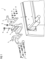
- Fig.1 shows an exemplary and schematic illustration of an adjustment device in an exploded view. It shows an adjustment device 1, as it can be used in practical applications and which is constructed according to the first embodiment, in which a threaded spindle is arranged in a recess of a door drive-side bracket.
- the adjustment device 1 comprises a door drive-side bracket 4, which is manufactured, for example, in two pieces from a milled part and a plate welded thereto, and two car body-side brackets 5. It is advantageous to provide two car body-side brackets 5 for each door drive-side bracket 4, as this better distributes the force introduced into the car body.
- the car body-side brackets 5 are designed for mounting on a car body, typically on C-rails, and have corresponding holes for screw connections.
- the threaded rods 6 can be adjusted separately in their position relative to the door drive-side bracket 4.
- both a height adjustment of the door drive 2 is possible by simultaneously adjusting the threaded rods 6, and an adjustment of the angular position by unilaterally adjusting one of the threaded rods 6.
- the angular position of the door drive 2 can also be adjusted about a transverse axis of the car body, for which purpose both threaded rods 6 of one device 1 are adjusted simultaneously and the threaded rods 6 of the second device 1 are not adjusted or are adjusted in the opposite direction.
Landscapes
- Engineering & Computer Science (AREA)
- Mechanical Engineering (AREA)
- Vehicle Step Arrangements And Article Storage (AREA)
- Power-Operated Mechanisms For Wings (AREA)
- Lock And Its Accessories (AREA)
Description
- Einrichtung zur Justierung eines Türantriebs.
- Die Erfindung betrifft eine Einrichtung zur Justierung eines Türantriebs in Bezug auf einen Wagenkasten eines Fahrzeugs.
- Türen von Passagierfahrzeugen, beispielsweise Schienenfahrzeugen für den Nahverkehr wie U-Bahnen oder S-Bahnen sind meist mit ein oder zweiflügeligen Schiebetüren oder Schwenk-Schiebetüren ausgestattet. Diese sind praktisch immer mit einem Türantrieb ausgestattet, welcher auf die Türblätter wirkt und sie zwischen einer offenen und einer geschlossenen Position bewegt. Dabei ist der Türantrieb meist als vormontierte Funktionseinheit aufgebaut, welche im Dachbereich des Fahrzeugs oberhalb der Türöffnung angeordnet ist. Die Montage dieser Baugruppe muß sehr exakt erfolgen, da die Lage der Türblätter in Bezug auf den Wagenkasten des Fahrzeugs durch die Montage des Türantriebs bestimmt ist. Somit ist der Türantrieb in allen Raumrichtungen und allen Winkellagen exakt zu befestigen, da sonst eine Fehllage der Türblätter eintritt, was einerseits einen optisch nachteiligen Eindruck des Fahrzeugs bewirkt als auch zu Funktionsstörungen bei der Türbetätigung führen kann. Der Türantrieb wird an bestimmten Festpunkten des Wagenkastens angeordnet, wozu sich beispielsweise C-Schienen an den Leichtmetallprofilen von Wagenkästen in Integralbauweise sehr gut eignen. Jedoch ist die Lage dieser Festpunkte Toleranzen unterworfen, wie sie während des Fertigungsprozesses des Wagenkastens, insbesondere beim Schweißen, auftreten. Somit ist die Justierung des Türantriebs ein aufwendiger und zeitraubender Prozess, bei welchem unterschiedlich dicke Zwischenlagen zwischen den Festpunkten und dem Türantrieb und dem Wagenkasten angeordnet werden müssen. Zum technischen Umfeld wird auf die
EP 1 767 389 A2 und dieDE 20 2014 102405 U1 verwiesen. - Der Erfindung liegt daher die Aufgabe zugrunde, eine Einrichtung zur Justierung eines Türantriebs in Bezug auf einen Wagenkasten eines Fahrzeugs anzugeben, mittels welcher es gelingt, diese Justierung rasch und einfach und insbesondere ohne weitere Bauteile wie Zwischenlagen durchführen zu können.
- Die Aufgabe wird durch eine Einrichtung zur Justierung eines Türantriebs in Bezug auf einen Wagenkasten eines Fahrzeugs für ein Schienenfahrzeug mit den Merkmalen des Anspruchs 1 gelöst. Vorteilhafte Ausgestaltungen sind Gegenstand untergeordneter Ansprüche.
- Dem Grundgedanken der Erfindung nach wird eine Einrichtung zur Justierung eines Türantriebs in Bezug auf einen Wagenkasten eines Fahrzeugs beschrieben, wobei mindestens eine türantriebsseitige Konsole vorgesehen ist, welche zur lösbaren Anordnung an einem Türantrieb ausgebildet ist und mindestens eine wagenkastenseitige Konsole vorgesehen ist, welche zur lösbaren Anordnung ein einem Wagenkasten ausgebildet ist, wobei die Lage der türantriebsseitige Konsole zu der wagenkastenseitige Konsole mittels mindestens einer Gewindestange verstellbar ist und wobei die türantriebsseitige Konsole mit der wagenkastenseitigen Konsole mittels einer Schraubverbindung fixierbar ist. Dadurch ist der Vorteil erzielbar, einen Türantrieb gegenüber einem Wagenkasten rasch, einfach und exakt positionieren zu können und nach erfolgter Justierung der relativen Lage mittels einer an der Einrichtung vorgesehenen Schraubverbindung den Türantrieb fest und lösbar mit dem Wagenkasten verbinden zu können. Dies kann auch mit bereits an dem Türantrieb befestigten Türblättern (Türmodul) erfolgen. Letzteres ist insbesondere vorteilhaft, da dadurch auch in demselben Arbeitsgang auch die Lage der Türblätter zu dem Wagenkasten justiert werden kann.
- Ein weiterer wesentlicher Vorteil gegenständlicher Erfindung liegt darin, dass mit der Justiereinrichtung der Türantrieb in zwei Raumrichtungen (jeweils normal zur Wagenkastenlängsachse) linear justierbar ist und der Winkel des Türantriebs in Bezug auf den Wagenkasten um jede Drehachse justierbar ist. Solcherart kann der Arbeitsaufwand der Türmontage und Justierung extrem verkürzt werden.
- Erfindungsgemäß ist eine Einrichtung vorgesehen, welche zwei Konsolen umfasst, wobei eine der Konsolen zur Befestigung an dem Wagenkasten vorgesehen ist und eine weitere Konsole zur Befestigung an dem Türantrieb vorgesehen ist. Dabei sind die Konsolen so gestaltet, dass sie mittels einer Schraubverbindung miteinander fest und lösbar verbindbar sind. Die türantriebsseitige Konsole ist mit einer Aufnahme für eine Gewindespindel ausgestattet, welche es erlaubt, die Schraubverbindung zur Verbindung der beiden Konsolen in einer Raumrichtung in Bezug auf die türantriebsseitige Konsole zu justieren. Dazu ist die Gewindespindel mit einer Ausformung ausgestattet, welche eine Bohrung umfasst durch welche die Schraubverbindung zur Verbindung der beiden Konsolen durchgeführt ist. Die Gewindespindel ist mittels einer Mutter entlang ihrer Längsachse verschiebbar, wodurch sich die Verstellung der Lage der Schraubverbindung ergibt.
- Die Schraubverbindung zur Verbindung der beiden Konsolen ist sowohl in der türantriebsseitigen Konsole als auch in der wagenkastenseitigen Konsole durch Langlöcher geführt, sodass ein bestimmter Verschiebeweg in zwei Raumrichtungen verbleibt. Diese Raumrichtungen sind vorzugsweise so anzuordnen, dass mittels der Gewindespindel der Türantrieb in Bezug auf den Wagenkasten in seiner relativen Höhe und quer zur Wagenkastenlängsachse justierbar ist. Die ebenso erforderliche Justierung entlang der Wagenkastenlängsachse kann typischerweise bereits durch die Befestigung der wagenkastenseitigen Konsolen an C-Schienen des Wagenkastens sehr einfach vorgenommen werden.
- Besonders vorteilhaft ist es, je türantriebsseitiger Konsole zwei, entlang der Querachse des Wagenkastens versetze Gewindestangen vorzusehen und je Türantrieb zwei entlang der Längsachse des Wagenkastens versetze türantriebsseitige Konsolen vorzusehen. Ein solcherart montierter Türantrieb kann durch einfaches Betätigen der Gewindestangen über zugehörige Muttern in allen erforderlichen Raumrichtungen und Winkeln justiert und anschließend durch Spannen der Schraubverbindungen in seiner optimalen Lage fixiert werden. Insbesondere ist dabei vorteilhaft, dass während der Justierarbeiten ein gesamtes Türmodul (Türantrieb mit Türblätter) bereits lose an dem Wagenkasten angeordnet ist und während der Justierung keine Trageinrichtungen wie Kräne mehr erforderlich sind.
- Es zeigen beispielhaft:
-
Fig.1 Justiereinrichtung Explosionsdarstellung. -
Fig.2 Justiereinrichtung Schnittdarstellung. -
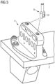
Fig.3 Justiereinrichtung 1. Montageschritt. -
Fig.4 Justiereinrichtung 2. Montageschritt. -
Fig.5 Justiereinrichtung 3. Montageschritt. -
Fig.1 zeigt beispielhaft und schematisch eine Justiereinrichtung in einer Explosionsdarstellung. Es ist eine Justiereinrichtung 1 gezeigt, wie sie in praktischen Anwendungen zum Einsatz kommen kann und welche nach der ersten Ausführungsform, bei welcher eine Gewindespindel in einer Ausnehmung einer türantriebsseitigen Konsole angeordnet ist, aufgebaut ist. Die Justiereinrichtung 1 umfasst eine türantriebsseitige Konsole 4, welche beispielshaft zweistückig aus einem Frästeil und einer daran angeschweißten Platte hergestellt ist und zwei wagenkastenseitige Konsolen 5. Es ist vorteilhaft je türantriebsseitiger Konsole 4 zwei wagenkastenseitige Konsolen 5 vorzusehen, da solcherart die Krafteinleitung in den Wagenkasten besser verteilt ist. Die wagenkastenseitigen Konsolen 5 sind zur Montage an einem Wagenkasten, typsicherweise an C-Schienen, ausgebildet und weist entsprechende Bohrungen für Schraubverbindungen auf. In Einbaulage ist die türantriebsseitige Konsole 4 von jeweils einer wagenkastenseitigen Konsole 5 benachbart und kann mittels der Schrauben 7 und der zugehörigen Muttern 8 fest und lösbar mit diesen wagenkastenseitigen Konsolen 5 verbunden werden. Somit ist auch eine feste Verbindung des Türantriebs 2 mit dem Wagenkasten hergestellt. Die türantriebsseitige Konsole 4 umfasst Ausnehmungen in welche Gewindestangen 6 einbringbar sind. Gezeigtes Ausführungsbeispiel stellt zwei Gewindestangen 6 dar, jedoch kann unter Verzicht auf die Einstellbarkeit der Winkellage des Türantriebs 2 auch nur eine Gewindestange 6 vorgesehen werden. Die Gewindestangen 6 weisen einen Abschnitt mit einem Außengewinde auf und eine Ausformung, welche einen von der Kreisform des Querschnitts des Gewindeabschnitts abweicht. Somit sind die Gewindestangen 6 in der Ausnehmung der türantriebsseitigen Konsole 4 längsverschiebbar und gegen Verdrehen gesichert. In dieser Ausformung der Gewindestangen 6 ist eine Bohrung angeordnet, durch welche die Schrauben 7 geführt sind. In der folgendenFig. 2 ist diese Anordnung deutlich erkennbar. Es sind zwei der drei Schrauben 7 durch die Gewindestangen 6 geführt, die dritte durchdringt nur die türantriebsseitige Konsole 4. Dadurch ist die Lage des Türantriebs 2 verspannungsfrei einstellbar. Die Längsverschiebung der Gewindestangen 6 erfolgt mittels je einer Justiermutter 9, welche in das Gewinde der zugehörigen Gewindestange 6 eingreift und welche ihrerseits in einer Ausnehmung der türantriebsseitigen Konsole 4 drehbeweglich aber axial fixiert angeordnet ist. Somit können den Gewindestangen 6 getrennt voneinander in ihrer Lage zu der türantriebsseitigen Konsole 4 eingestellt werden. Dabei ist sowohl eine Höheneinstellung des Türantriebs 2 durch gleichzeitiges Verstellen der Gewindestangen 6 möglich, als auch eine Einstellung der Winkellage durch einseitiges Verstellen einer der Gewindestangen 6. Da in praktischen Anwendungsfällen zwei erfindungsgemäße Einrichtungen 1 an je einem Ende eines Türantriebs 2 vorgesehen werden, kann auch die Winkellage des Türantriebs 2 um eine Querachse des Wagenkastens justiert werden, wozu beide Gewindestangen 6 einer Einrichtung 1 gleichzeitig verstellt werden und die Gewindestangen 6 der zweiten Einrichtung 1 nicht oder entgegengesetzt verstellt werden. -
Fig.2 zeigt beispielhaft und schematisch eine Justiereinrichtung 1 in einer Schnittdarstellung. Es ist ein Schnitt durch eine türantriebsseitige Konsole 4 in Montageposition dargestellt. Der Schnitt ist dabei quer zur Längsrichtung eines Wagenkastens 3 ausgerichtet. Der Wagenkasten 3 ist in Integralbauweise aus einer Mehrzahl von Leichtmetallstrangpreßprofilen dargestellt und weist C-Schienen auf an welchen die wagenkastenseitigen Konsolen 5 mittels Schraubverbindungen lösbar befestigt sind. An der türantriebsseitigen Konsole 4 ist ein Türantrieb 2 angeordnet, welcher gegenüber dem Wagenkasten 3 justierbar ist. In dieser Schnittdarstellung ist die Anordnung der Gewindestangen 6 und der Justiermuttern 9 gut erkennbar. Zwei der drei Schrauben 7 durchdringen die Ausformungen der Gewindestangen 6, welche dazu je eine Bohrung 10 aufweisen. Die dritte Schraube 7 durchdringt die türantriebsseitige Konsole 4 durch ein vertikal ausgerichtetes Langloch und kann somit dem Verstellen der Gewindestangen 6 folgen. Die Justiermuttern 9 sind ein Ausnehmungen der türantriebsseitigen Konsole 4 geführt und sind drehbar, nicht jedoch axial verschiebbar. -
Fig.3 zeigt beispielhaft und schematisch eine Justiereinrichtung 1 bei einem 1. Montageschritt. Bei diesem ersten Montageschritt wird die türantriebsseitige Konsole 4 mittels Schraubverbindungen an einem Türantrieb 2 befestigt. Die Gewindestangen 6 sind dabei in den zugehörigen Ausnehmungen der türantriebsseitigen Konsole 4 eingelegt. -
Fig.4 zeigt beispielhaft und schematisch eine Justiereinrichtung 1 bei einem 2. Montageschritt. Bei diesem weiteren Montagschritt sind die Justiermuttern 9 in ihre Ausnehmungen eingelegt und ihre Innengewinde sind mit dem Außengewinde der Gewindestangen 6 im Eingriff. Die türantriebsseitige Konsole 4 ist gemeinsam mit dem Türantrieb 2 in ihre Montageposition gebracht, aber noch nicht mit den wagenkastenseitigen Konsolen 5 verbunden. Der Wagenkasten selbst ist inFig.4 zur Verdeutlichung des Montageprinzips nicht dargestellt. -
Fig.5 zeigt beispielhaft und schematisch eine Justiereinrichtung 1 bei einem 3. Montageschritt. In diesem darauffolgenden Montageschritt sind die Schrauben 7 in ihrer Montageposition und mit Muttern 8 im Eingriff. Dabei ist der Türantrieb 2 lose mit dem Wagenkasten verbunden, kann jedoch nicht mehr abfallen und die vorher erforderlichen Hebemittel können entfernt werden. In diesem Montageschritt kann die Lage des Türantriebs 2 durch Verstellen den Justiermuttern 9 justiert werden. Ist diese Lage korrekt, so können die Schraubverbindungen 7, 8 angezogen werden. -
- 1
- Justiereinrichtung
- 2
- Türantrieb
- 3
- Wagenkasten
- 4
- Türantriebsseitige Konsole
- 5
- Wagenkastenseitige Konsole
- 6
- Gewindestange
- 7
- Schraube
- 8
- Mutter
- 9
- Justiermutter
- 10
- Bohrung
Claims (6)
- Einrichtung (1) zur Justierung eines Türantriebs (2) in Bezug auf einen Wagenkasten (3) eines Fahrzeugs, wobei mindestens eine türantriebsseitige Konsole (4) vorgesehen ist, welche zur lösbaren Anordnung an einem Türantrieb (2) ausgebildet ist und mindestens eine wagenkastenseitige Konsole (5) vorgesehen ist, welche zur lösbaren Anordnung ein einem Wagenkasten (3) ausgebildet ist und wobei die türantriebsseitige Konsole (4) mit der wagenkastenseitigen Konsole (5) mittels einer Schraubverbindung (7, 8) fixierbar ist, und wobei die Lage der türantriebsseitigen Konsole (4) zu der wagenkastenseitigen Konsole (5) mittels mindestens einer Gewindestange (6) verstellbar ist dadurch gekennzeichnet, dass die Gewindestange (6) in einer Ausnehmung der türantriebsseitigen Konsole (4) geführt ist, wobei die Lage der Gewindestange (6) in Bezug auf die türantriebsseitige Konsole (4) mittels einer Justiermutter (9) einstellbar ist und wobei die Gewindestange (6) eine Ausformung aufweist, welche mit einer Bohrung (10) ausgestattet ist, wobei in Gebrauchslage der Einrichtung (1) die Schraubverbindung (7, 8) zur Fixierung der türantriebsseitige Konsole (4) mit der wagenkastenseitigen Konsole (5) durch diese Bohrung (10) geführt ist.
- Einrichtung (1) zur Justierung eines Türantriebs (2) in Bezug auf einen Wagenkasten (3) nach dem Anspruch 1,
dadurch gekennzeichnet, dass die Schraube (7), zur Fixierung der türantriebsseitige Konsole (4) mit der wagenkastenseitigen Konsole (5) an der wagenkastenseitigen Konsole (5) in einem horizontal ausgerichteten Langloch schiebbar angeordnet ist. - Einrichtung (1) zur Justierung eines Türantriebs (2) in Bezug auf einen Wagenkasten (3) nach einem der Ansprüche 1 bis 2,
dadurch gekennzeichnet, dass die Schraube (7) zur Fixierung der türantriebsseitige Konsole (4) mit der wagenkastenseitigen Konsole (5) an der türantriebsseitigen Konsole (4) in einem vertikal ausgerichteten Langloch schiebbar angeordnet ist. - Einrichtung (1) zur Justierung eines Türantriebs (2) in Bezug auf einen Wagenkasten (3) nach einem der Ansprüche 1 bis 3,
dadurch gekennzeichnet, dass je Türantrieb (2) zwei türantriebsseitige Konsolen (4) mit jeweils zwei wagenkastenseitigen Konsolen (5) vorgesehen sind. - Einrichtung (1) zur Justierung eines Türantriebs (2) in Bezug auf einen Wagenkasten (3) nach einem der Ansprüche 1 bis 4,
dadurch gekennzeichnet, dass die türantriebsseitigen Konsolen (4) und die wagenkastenseitigen Konsolen (5) jeweils zur lösbaren Anordnung an C-Schienen des Türantriebs (2) bzw. C-Schienen des Wagenkastens (3) ausgebildet sind. - Einrichtung (1) zur Justierung eines Türantriebs (2) in Bezug auf einen Wagenkasten (3) nach einem der Ansprüche 1 bis 5,
dadurch gekennzeichnet, dass in einer Einrichtung (1) zwei Gewindestangen (6) vorgesehen sind.
Applications Claiming Priority (2)
| Application Number | Priority Date | Filing Date | Title |
|---|---|---|---|
| ATA50899/2018A AT521876B1 (de) | 2018-10-17 | 2018-10-17 | Einrichtung zur Justierung eines Türantriebs |
| PCT/EP2019/074720 WO2020078638A1 (de) | 2018-10-17 | 2019-09-16 | Einrichtung zur justierung eines türantriebs |
Publications (2)
| Publication Number | Publication Date |
|---|---|
| EP3850175A1 EP3850175A1 (de) | 2021-07-21 |
| EP3850175B1 true EP3850175B1 (de) | 2025-07-09 |
Family
ID=68072327
Family Applications (1)
| Application Number | Title | Priority Date | Filing Date |
|---|---|---|---|
| EP19778856.5A Active EP3850175B1 (de) | 2018-10-17 | 2019-09-16 | Einrichtung zur justierung eines türantriebs |
Country Status (4)
| Country | Link |
|---|---|
| EP (1) | EP3850175B1 (de) |
| AT (1) | AT521876B1 (de) |
| ES (1) | ES3046882T3 (de) |
| WO (1) | WO2020078638A1 (de) |
Family Cites Families (7)
| Publication number | Priority date | Publication date | Assignee | Title |
|---|---|---|---|---|
| DE8322167U1 (de) * | 1983-08-01 | 1983-12-08 | Kiekert GmbH & Co KG, 5628 Heiligenhaus | Schwenkschiebetueraufhaengung fuer fahrzeuge |
| DE20316764U1 (de) * | 2003-10-31 | 2005-03-17 | Bode Gmbh & Co Kg | Schwenkschiebetür für Fahrzeuge, insbesondere Fahrgasttür für Fahrzeuge des öffentlichen Personennahverkehrs |
| DE202005015168U1 (de) * | 2005-09-27 | 2007-02-15 | Gebr. Bode Gmbh & Co. Kg | Schwenkschiebetür für Fahrzeuge, insbesondere Fahrgasttür für Fahrzeuge des öffentlichen Personennahverkehrs |
| JP4925952B2 (ja) * | 2007-07-18 | 2012-05-09 | 川崎重工業株式会社 | 鉄道車両用側引き戸装置 |
| KR20110130326A (ko) * | 2010-05-27 | 2011-12-05 | 임창선 | 도어 회전장치 |
| DE202014102405U1 (de) * | 2014-05-22 | 2015-08-28 | Gebr. Bode Gmbh & Co. Kg | Verriegelungsvorrichtung für Schwenkschiebetüren von Fahrzeugen des öffentlichen Personenverkehrs; Schwenkschiebetür mit Verriegelungsvorrichtung |
| AT516488B1 (de) * | 2014-10-27 | 2016-09-15 | Siemens Ag Oesterreich | Einrichtung zur vertikalen Einstellung einer Schienenfahrzeugtür |
-
2018
- 2018-10-17 AT ATA50899/2018A patent/AT521876B1/de active
-
2019
- 2019-09-16 ES ES19778856T patent/ES3046882T3/es active Active
- 2019-09-16 WO PCT/EP2019/074720 patent/WO2020078638A1/de not_active Ceased
- 2019-09-16 EP EP19778856.5A patent/EP3850175B1/de active Active
Also Published As
| Publication number | Publication date |
|---|---|
| ES3046882T3 (en) | 2025-12-02 |
| EP3850175A1 (de) | 2021-07-21 |
| WO2020078638A1 (de) | 2020-04-23 |
| AT521876B1 (de) | 2022-10-15 |
| AT521876A1 (de) | 2020-05-15 |
Similar Documents
| Publication | Publication Date | Title |
|---|---|---|
| EP3271538B1 (de) | Tür- oder fensterscharnier | |
| EP2742199B1 (de) | Befestigungsanordnung zur befestigung eines bauteils an einer nut eines fensters, einer tür oder dergleichen | |
| EP3445935B1 (de) | Schiebetüranlage | |
| EP3486420B1 (de) | Vorrichtung zum positionieren eines fensters oder einer tür | |
| DE102012105575B4 (de) | Lagerungseinheit | |
| EP2591192A1 (de) | Vorrichtung zum einstellen und arretieren der lage einer führungsschiene für eine verstellbare fensterscheibe in einer fahrzeugtür | |
| EP3656960B1 (de) | Stellglied und lagerungseinrichtung für eine klappe | |
| EP2430276B1 (de) | Schiebetürsystem für schienenfahrzeuge | |
| EP3150786A1 (de) | Gelenkverbindung | |
| EP1582675A1 (de) | Vorrichtung zur Aufnahme eines Türblattes für Futterzargen | |
| EP3850175B1 (de) | Einrichtung zur justierung eines türantriebs | |
| EP2149664B1 (de) | Unterkonstruktion für ein Scharnierband und Scharnierband mit einer solchen Unterkonstruktion zur Befestigung an einem Türblatt | |
| DE102015012641B3 (de) | Gelenkverbindung | |
| DE102018105959B4 (de) | Montageanordnung eines Luftleitelements | |
| EP2470735B1 (de) | Türbeschlag | |
| EP3523160B1 (de) | Getriebeanordnung für einen spindelantrieb, spindelantrieb und fahrzeugsitz | |
| EP3786405B1 (de) | Möbelantrieb zum bewegen eines bewegbar gelagerten möbelteiles | |
| EP2740872B1 (de) | Zur verdeckten anordnung vorgesehenes ecklager | |
| DE202004004407U1 (de) | Zug-Druck-Stange | |
| AT524324B1 (de) | Lagerungsvorrichtung zur Lagerung wenigstens eines Türflügels | |
| DE10021898C2 (de) | Vorrichtung zum Verstellen von relativ zueinander beweglichen Teilen | |
| DE202015003728U1 (de) | Drehflügeltür mit Torsionsstab | |
| DE10319955B4 (de) | Verstelleinrichtung | |
| EP1724427A2 (de) | Vorrichtung zur Einstellung der Lage einer Führungsschiene eines Fensterhebers | |
| DE10243496A1 (de) | Vorrichtung zum Verbinden von Seitenscheiben eines Kraftfahrzeugs mit einem zugeordneten Fensterheber |
Legal Events
| Date | Code | Title | Description |
|---|---|---|---|
| STAA | Information on the status of an ep patent application or granted ep patent |
Free format text: STATUS: UNKNOWN |
|
| STAA | Information on the status of an ep patent application or granted ep patent |
Free format text: STATUS: THE INTERNATIONAL PUBLICATION HAS BEEN MADE |
|
| PUAI | Public reference made under article 153(3) epc to a published international application that has entered the european phase |
Free format text: ORIGINAL CODE: 0009012 |
|
| STAA | Information on the status of an ep patent application or granted ep patent |
Free format text: STATUS: REQUEST FOR EXAMINATION WAS MADE |
|
| 17P | Request for examination filed |
Effective date: 20210412 |
|
| AK | Designated contracting states |
Kind code of ref document: A1 Designated state(s): AL AT BE BG CH CY CZ DE DK EE ES FI FR GB GR HR HU IE IS IT LI LT LU LV MC MK MT NL NO PL PT RO RS SE SI SK SM TR |
|
| DAV | Request for validation of the european patent (deleted) | ||
| DAX | Request for extension of the european patent (deleted) | ||
| STAA | Information on the status of an ep patent application or granted ep patent |
Free format text: STATUS: EXAMINATION IS IN PROGRESS |
|
| 17Q | First examination report despatched |
Effective date: 20231102 |
|
| GRAP | Despatch of communication of intention to grant a patent |
Free format text: ORIGINAL CODE: EPIDOSNIGR1 |
|
| STAA | Information on the status of an ep patent application or granted ep patent |
Free format text: STATUS: GRANT OF PATENT IS INTENDED |
|
| INTG | Intention to grant announced |
Effective date: 20250321 |
|
| GRAS | Grant fee paid |
Free format text: ORIGINAL CODE: EPIDOSNIGR3 |
|
| GRAA | (expected) grant |
Free format text: ORIGINAL CODE: 0009210 |
|
| STAA | Information on the status of an ep patent application or granted ep patent |
Free format text: STATUS: THE PATENT HAS BEEN GRANTED |
|
| AK | Designated contracting states |
Kind code of ref document: B1 Designated state(s): AL AT BE BG CH CY CZ DE DK EE ES FI FR GB GR HR HU IE IS IT LI LT LU LV MC MK MT NL NO PL PT RO RS SE SI SK SM TR |
|
| REG | Reference to a national code |
Ref country code: GB Ref legal event code: FG4D Free format text: NOT ENGLISH |
|
| REG | Reference to a national code |
Ref country code: CH Ref legal event code: EP |
|
| REG | Reference to a national code |
Ref country code: IE Ref legal event code: FG4D Free format text: LANGUAGE OF EP DOCUMENT: GERMAN |
|
| REG | Reference to a national code |
Ref country code: DE Ref legal event code: R096 Ref document number: 502019013593 Country of ref document: DE |
|
| PGFP | Annual fee paid to national office [announced via postgrant information from national office to epo] |
Ref country code: FR Payment date: 20250915 Year of fee payment: 7 |
|
| REG | Reference to a national code |
Ref country code: NL Ref legal event code: MP Effective date: 20250709 |
|
| REG | Reference to a national code |
Ref country code: ES Ref legal event code: FG2A Ref document number: 3046882 Country of ref document: ES Kind code of ref document: T3 Effective date: 20251202 |
|
| PG25 | Lapsed in a contracting state [announced via postgrant information from national office to epo] |
Ref country code: PT Free format text: LAPSE BECAUSE OF FAILURE TO SUBMIT A TRANSLATION OF THE DESCRIPTION OR TO PAY THE FEE WITHIN THE PRESCRIBED TIME-LIMIT Effective date: 20251110 |
|
| REG | Reference to a national code |
Ref country code: CH Ref legal event code: U11 Free format text: ST27 STATUS EVENT CODE: U-0-0-U10-U11 (AS PROVIDED BY THE NATIONAL OFFICE) Effective date: 20251210 |
|
| PG25 | Lapsed in a contracting state [announced via postgrant information from national office to epo] |
Ref country code: NL Free format text: LAPSE BECAUSE OF FAILURE TO SUBMIT A TRANSLATION OF THE DESCRIPTION OR TO PAY THE FEE WITHIN THE PRESCRIBED TIME-LIMIT Effective date: 20250709 |
|
| PG25 | Lapsed in a contracting state [announced via postgrant information from national office to epo] |
Ref country code: IS Free format text: LAPSE BECAUSE OF FAILURE TO SUBMIT A TRANSLATION OF THE DESCRIPTION OR TO PAY THE FEE WITHIN THE PRESCRIBED TIME-LIMIT Effective date: 20251109 |
|
| PGFP | Annual fee paid to national office [announced via postgrant information from national office to epo] |
Ref country code: DE Payment date: 20251120 Year of fee payment: 7 |
|
| PGFP | Annual fee paid to national office [announced via postgrant information from national office to epo] |
Ref country code: GB Payment date: 20251002 Year of fee payment: 7 |
|
| PG25 | Lapsed in a contracting state [announced via postgrant information from national office to epo] |
Ref country code: NO Free format text: LAPSE BECAUSE OF FAILURE TO SUBMIT A TRANSLATION OF THE DESCRIPTION OR TO PAY THE FEE WITHIN THE PRESCRIBED TIME-LIMIT Effective date: 20251009 |
|
| REG | Reference to a national code |
Ref country code: LT Ref legal event code: MG9D |
|
| PG25 | Lapsed in a contracting state [announced via postgrant information from national office to epo] |
Ref country code: FI Free format text: LAPSE BECAUSE OF FAILURE TO SUBMIT A TRANSLATION OF THE DESCRIPTION OR TO PAY THE FEE WITHIN THE PRESCRIBED TIME-LIMIT Effective date: 20250709 |
|
| PG25 | Lapsed in a contracting state [announced via postgrant information from national office to epo] |
Ref country code: HR Free format text: LAPSE BECAUSE OF FAILURE TO SUBMIT A TRANSLATION OF THE DESCRIPTION OR TO PAY THE FEE WITHIN THE PRESCRIBED TIME-LIMIT Effective date: 20250709 |
|
| PG25 | Lapsed in a contracting state [announced via postgrant information from national office to epo] |
Ref country code: GR Free format text: LAPSE BECAUSE OF FAILURE TO SUBMIT A TRANSLATION OF THE DESCRIPTION OR TO PAY THE FEE WITHIN THE PRESCRIBED TIME-LIMIT Effective date: 20251010 |
|
| PGFP | Annual fee paid to national office [announced via postgrant information from national office to epo] |
Ref country code: CH Payment date: 20251210 Year of fee payment: 7 |
|
| PG25 | Lapsed in a contracting state [announced via postgrant information from national office to epo] |
Ref country code: SE Free format text: LAPSE BECAUSE OF FAILURE TO SUBMIT A TRANSLATION OF THE DESCRIPTION OR TO PAY THE FEE WITHIN THE PRESCRIBED TIME-LIMIT Effective date: 20250709 |
|
| PG25 | Lapsed in a contracting state [announced via postgrant information from national office to epo] |
Ref country code: LV Free format text: LAPSE BECAUSE OF FAILURE TO SUBMIT A TRANSLATION OF THE DESCRIPTION OR TO PAY THE FEE WITHIN THE PRESCRIBED TIME-LIMIT Effective date: 20250709 |
|
| PG25 | Lapsed in a contracting state [announced via postgrant information from national office to epo] |
Ref country code: PL Free format text: LAPSE BECAUSE OF FAILURE TO SUBMIT A TRANSLATION OF THE DESCRIPTION OR TO PAY THE FEE WITHIN THE PRESCRIBED TIME-LIMIT Effective date: 20250709 Ref country code: BG Free format text: LAPSE BECAUSE OF FAILURE TO SUBMIT A TRANSLATION OF THE DESCRIPTION OR TO PAY THE FEE WITHIN THE PRESCRIBED TIME-LIMIT Effective date: 20250709 |
|
| PG25 | Lapsed in a contracting state [announced via postgrant information from national office to epo] |
Ref country code: RS Free format text: LAPSE BECAUSE OF FAILURE TO SUBMIT A TRANSLATION OF THE DESCRIPTION OR TO PAY THE FEE WITHIN THE PRESCRIBED TIME-LIMIT Effective date: 20251009 |
|
| PGFP | Annual fee paid to national office [announced via postgrant information from national office to epo] |
Ref country code: ES Payment date: 20251219 Year of fee payment: 7 |
|
| PG25 | Lapsed in a contracting state [announced via postgrant information from national office to epo] |
Ref country code: RO Free format text: LAPSE BECAUSE OF FAILURE TO SUBMIT A TRANSLATION OF THE DESCRIPTION OR TO PAY THE FEE WITHIN THE PRESCRIBED TIME-LIMIT Effective date: 20250709 |
|
| PG25 | Lapsed in a contracting state [announced via postgrant information from national office to epo] |
Ref country code: SM Free format text: LAPSE BECAUSE OF FAILURE TO SUBMIT A TRANSLATION OF THE DESCRIPTION OR TO PAY THE FEE WITHIN THE PRESCRIBED TIME-LIMIT Effective date: 20250709 |
|
| PG25 | Lapsed in a contracting state [announced via postgrant information from national office to epo] |
Ref country code: DK Free format text: LAPSE BECAUSE OF FAILURE TO SUBMIT A TRANSLATION OF THE DESCRIPTION OR TO PAY THE FEE WITHIN THE PRESCRIBED TIME-LIMIT Effective date: 20250709 |
|
| PG25 | Lapsed in a contracting state [announced via postgrant information from national office to epo] |
Ref country code: IT Free format text: LAPSE BECAUSE OF FAILURE TO SUBMIT A TRANSLATION OF THE DESCRIPTION OR TO PAY THE FEE WITHIN THE PRESCRIBED TIME-LIMIT Effective date: 20250709 |