EP3851280A1 - Dispositif de manipulation de plaques d'impression sur une machine d'impression - Google Patents
Dispositif de manipulation de plaques d'impression sur une machine d'impression Download PDFInfo
- Publication number
- EP3851280A1 EP3851280A1 EP20180239.4A EP20180239A EP3851280A1 EP 3851280 A1 EP3851280 A1 EP 3851280A1 EP 20180239 A EP20180239 A EP 20180239A EP 3851280 A1 EP3851280 A1 EP 3851280A1
- Authority
- EP
- European Patent Office
- Prior art keywords
- pallet
- printing
- bolt
- plates
- actuator
- Prior art date
- Legal status (The legal status is an assumption and is not a legal conclusion. Google has not performed a legal analysis and makes no representation as to the accuracy of the status listed.)
- Granted
Links
Images


Classifications
-
- B—PERFORMING OPERATIONS; TRANSPORTING
- B41—PRINTING; LINING MACHINES; TYPEWRITERS; STAMPS
- B41F—PRINTING MACHINES OR PRESSES
- B41F27/00—Devices for attaching printing elements or formes to supports
- B41F27/12—Devices for attaching printing elements or formes to supports for attaching flexible printing formes
- B41F27/1206—Feeding to or removing from the forme cylinder
-
- B—PERFORMING OPERATIONS; TRANSPORTING
- B41—PRINTING; LINING MACHINES; TYPEWRITERS; STAMPS
- B41F—PRINTING MACHINES OR PRESSES
- B41F27/00—Devices for attaching printing elements or formes to supports
- B41F27/12—Devices for attaching printing elements or formes to supports for attaching flexible printing formes
-
- B—PERFORMING OPERATIONS; TRANSPORTING
- B41—PRINTING; LINING MACHINES; TYPEWRITERS; STAMPS
- B41P—INDEXING SCHEME RELATING TO PRINTING, LINING MACHINES, TYPEWRITERS, AND TO STAMPS
- B41P2227/00—Mounting or handling printing plates; Forming printing surfaces in situ
- B41P2227/50—Devices for storing printing plates
-
- B—PERFORMING OPERATIONS; TRANSPORTING
- B41—PRINTING; LINING MACHINES; TYPEWRITERS; STAMPS
- B41P—INDEXING SCHEME RELATING TO PRINTING, LINING MACHINES, TYPEWRITERS, AND TO STAMPS
- B41P2227/00—Mounting or handling printing plates; Forming printing surfaces in situ
- B41P2227/60—Devices for transferring printing plates
- B41P2227/62—Devices for introducing printing plates
-
- B—PERFORMING OPERATIONS; TRANSPORTING
- B41—PRINTING; LINING MACHINES; TYPEWRITERS; STAMPS
- B41P—INDEXING SCHEME RELATING TO PRINTING, LINING MACHINES, TYPEWRITERS, AND TO STAMPS
- B41P2227/00—Mounting or handling printing plates; Forming printing surfaces in situ
- B41P2227/60—Devices for transferring printing plates
- B41P2227/63—Devices for removing printing plates
Definitions
- the present invention relates to a device for handling printing plates on a printing press, comprising at least one pallet for receiving the printing plates.
- a device for handling printing plates on a printing machine comprising at least one pallet for receiving the printing plates, characterized in that a latch for securing the printing plates is present in the pallet, the latch being part of the pallet on this is attached, and an actuator for actuating the bolt is arranged on a component of the device which is separate from the pallet.
- a pallet is also understood to mean a tray or tray or a bowl.
- the latch prevents the pressure plates from falling off the pallet, even with abrupt pallet movements and critical pallet positions.
- An additional advantage is that the arrangement of the actuator makes it possible to use it for actuating the bolts of several pallets, preferably one after the other.
- the printing machine can be an in-line sheet-fed printing machine, e.g. B. a perfector for perfecting.
- the printing press can have a sheet feeder and a sheet delivery.
- the printing units mentioned can be offset printing units, the printing plates being offset printing plates.
- the printing press can have one or more additional printing units, e.g. B. Flexographic printing units for painting.
- the latch can be adjustable in a plane that extends parallel to the front and rear edges of the pressure plates located in the pallet. The plane can extend parallel to a bottom of the pallet. The bottom can form a closed surface or a perforated surface, e.g. B.
- the pallet can have side walls that border the floor.
- the bottom can be rectangular, the border of the bottom can be closed all around by the side walls, the pallet forming a shell, or it can not be present or open on one or more of the four sides.
- the bolt can be a sliding bolt that is linearly adjustable.
- a design of the bolt as a swivel bolt is preferred, the bolt being arranged so as to be pivotable about an axis. This geometric axis is oriented orthogonally relative to said plane in which the bolt is adjustable.
- the actuator can be an electric motor, combined, e.g. B. in the case of the slide latch, with a screw gear or combined, e.g. B. in the case of the swivel bolt, with a worm gear.
- a working cylinder e.g. B. as a hydraulic cylinder or preferably as a pneumatic cylinder.
- the coupling can be a coupling via which the bolt can be coupled to the actuator.
- the coupling comprises a first coupling half and a second coupling half, which is arranged on the actuator or the downstream gear (e.g. said screw or worm gear).
- the first coupling half is arranged on the pallet, especially on the bolt.
- a first coupling half can be arranged on each pallet, especially on each latch, it being possible for the first coupling halves to be structurally identical to one another.
- the coupling can be a plug-in coupling. With the plug-in coupling, the first coupling half and the second coupling half can be plugged together during coupling.
- the coupling can inevitably take place when the pallet and the component on which the actuator is arranged are brought into contact with one another.
- the plug-in coupling can have a pin, e.g. B. a pen or roller, and a recess, e.g. B. a slot, a groove or a bore, whereby the two coupling halves can be formed. As the pin enters the recess, the actuator and the bolt can be coupled to one another so that the actuator can drive the bolt via the closed coupling.
- clamp for securing the pressure plates in the pallet, wherein the clamp can be arranged on a component of the device that is separate from the pallet.
- This component can either be identical to that component or together form a structural unit on which the actuator is arranged.
- the clamp can be moved relative to the component to which it is attached to clamp the pressure plates in the pallet.
- the clamp can be adjustable in one plane, e.g. B. pivotable, which extends orthogonally to the leading and trailing edges of the printing plates in the pallet.
- the clamp can be pivotable about an axis. This geometric axis can extend parallel to the front and rear edges of the printing plates in the pallet.
- z. B. there can be several and z. B. there may be two such terminals that can work synchronously with each other and both on one and the same edge, z. b. can attack the rear edge with the rear edge or the front edge with the front edge, the top pressure plate of the plate stack in the pallet.
- the clamps can be arranged on different components which together form a structural unit, e.g. B. a pallet carrier.
- the latch can be in a release position for releasing the pressure plates and at the same time the clamp can be in a clamping position for securing the pressure plates.
- This operating situation can occur regularly, e.g. B. when removing the printing plates from the pallet.
- the clamp can clamp and release the printing plates in the pallet in a periodic change, e.g. B. in a conveying cycle of the printing plates with an automated removal of the printing plates (here: new plates) one after the other from the pallet and / or with an automated storage of the printing plates (here: old plates) one after the other in the pallet.
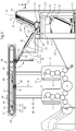
- a printing press 1 comprises printing units 2, 3 arranged in series for offset printing on sheets, which form a stack 5 in a feeder 4.
- Each printing unit 2, 3 is equipped with a plate changer 6, 7 for printing plates 8, which has a shaft 9 for fresh printing plates 8 - so-called new plates - and a shaft 10 for used printing plates 8 - so-called old plates.
- the printing machine 1 is combined with a plate logistics system which conveys the printing plates 8 to the plate changers 6, 7 and back again after use. The operator removes a pallet 12 with the pressure plates 8 therein from a floor conveyor 11 and transfers the pallet 12 to a pallet lift 13.
- the orthogonal coordinate system in the drawing includes the vertical direction z and horizontal directions x, y, where x corresponds to the longitudinal direction and y to the transverse direction of the printing press 1.
- the pallet lift 13 is arranged in front of the feeder 4 in the x direction and transports the pallet 12 along the z and y directions to a loading station 14, which is arranged above the stack 5 and a suction head 15 of the feeder 4.
- the loading station 14 serves to unload the new panels from the pallet 12 and to load them with old panels and has a first pallet carrier 16 and a second pallet carrier 17, which are arranged one behind the other in the y direction.
- the pallet lift 13 has a third pallet carrier 18.
- the first pallet carrier 16 and the second pallet carrier 17 are fastened via a plurality of coupling gears 19 to a slide 20 which, guided by a rail 21, is adjustable in the y direction.
- the third pallet carrier 18 reaches through that pallet carrier 16 or 17 which has previously been moved along the rail 21 in an opposite position aligned with the third pallet carrier 18 in the direction x. With this reaching through, the third pallet carrier 18 transfers or takes over the pallet to or from the other pallet carrier 16 or 17.
- a swivel arm 23 belonging to the loading station 14 and having a transport side 25 for the printing plates 8 can be swiveled about an axis 24 running in the y direction at its lower end.
- the pivot arm 23 is related to his Figure 1 left end position (drawn with full line) to its right end position (drawn with phantom line) and swiveled back again, and each time folded beyond its vertical alignment.
- the transport side 25 rises obliquely to the top right and extends parallel to the first pallet carrier 16 or second pallet carrier 17 and the respective pallet 12 or 26 therein.
- the transport side 25 rises obliquely to the top left and extends parallel or flush with a transport strand of a first conveyor belt 27 of a belt conveyor 28, which is arranged above a sheet feed table 29 of the feeder 4.
- the swivel arm 23 has lifting suction cups 30 which extend out of the transport side 25 and grip the respective uppermost pressure plate 8 of the plate stack on the pallet 12.
- the swivel arm 23 swivels with the pressure plate 8 sucked in by the lifting suckers 30 from the right to the left end position, where the lifting sucker 30 retracts into the swivel arm 23 in order to place the gripped pressure plate 8 on the first conveyor belt 27. Then the working cycle of the swivel arm 23 is repeated, which removes the pressure plates 8 one after the other from the pallet 12 and places them on the belt conveyor 28.
- the belt conveyor 28 comprises a second conveyor belt 31, which is alternately pivoted about a geometric axis 32 into a first operating position (drawn with a solid line) and a second operating position (drawn with a phantom line) by an actuator 52.
- the second conveyor belt 31 is vertically aligned in the first operating position and forms a common conveyor plane 33 with the first conveyor belt 27 in the second operating position.
- the two conveyor belts 27, 31 each consist of several endless belts that are of equal length and run parallel to one another around pulleys.
- deflection rollers over which the endless belts of the first conveyor belt 27 run, are arranged alternately with deflection rollers, over which the endless belts of the second conveyor belt 31 run. In other words: the endless belts of the second conveyor belt 31 run in a gap between the endless belts of the second conveyor belt 27.
- the swivel arm 23 has a row of prongs running in the y direction, which are aligned with the gaps between the endless belts of the first conveyor belt 27 and mesh with these gaps in the left end position of the swivel arm 23.
- the first and second conveyor belts 27, 31 are designed as suction belts, on which the printing plate 8 is held by vacuum during its transport, and each comprise a vacuum box.
- the vacuum box sucks in the pressure plate 8 through the gaps between the endless belts or perforations in the endless belts, so that it is pneumatically held on the endless belts.
- the belt conveyor 28 transfers the new panels to a panel conveyor 34, which is arranged above the printing units 2, 3, and later takes over the old panels from the panel conveyor 34.
- the plate conveyor 34 comprises carriages 35, the number of which corresponds to that of the printing units 2, 3 to be supplied with the printing plates 8.
- the carriages 35 are attached to or in engagement with an endless traction means 36, specifically a toothed belt, and are driven jointly via the traction means 36 by a drive wheel 37.
- the traction means 36 runs with respect to the conveying of the new plates from the loading station 14 to the printing units 6, 7 Figure 1 clockwise around and when conveying the old plates from the printing units 2, 3 to the loading station 14 counterclockwise.
- An electric motor connected to the drive wheel 37 as a direct drive is reversed accordingly in order to bring about the change in direction of the traction mechanism 36.
- a rail system 38 for guiding the carriages 35 comprises an upper rail section 39 and a lower rail section which is formed by a horizontal rail 40 which runs in the x direction.
- the entire rail system 38 has an oval or elongated ring shape, along which the carriages 35 circulate.
- the upper and lower rail pieces which are straight and run parallel to one another, are connected to one another at their ends by curved rail pieces.
- Self-supporting beams 41 with grippers 42 for holding the pressure plates 8 by clamping are arranged on the carriage 35.
- the beams 41 extend in the direction y over their length, wherein in the direction y each beam 41 is at least as long as the printing plate 8 is wide.
- the number of grippers 42 arranged in series on a shaft 49 per bar 41 is two in the example and can also be three. When they are transported synchronously with one another along the horizontal rail 40, the pressure plates 8 hang vertically on the beam 41.
- Control cams 44 for actuating the grippers 42, the carriages 35 with the bars 41, the rail system 38 for guiding the carriages 35 and the traction means 36 for driving the carriages 35 are arranged on a plate 43.
- the plate 43 is carried by stands 45, each of which is assigned to a different printing unit 2, 3.
- the stands 45 can be designed as telescopic rail guides 50.
- Each stand 45 forms or has a vertical rail 46 for guiding the plate 43.
- the plate 43 together with the said elements arranged thereon is adjusted upwards and downwards in the uprights 45 by one or more actuators (not shown in the drawing).
- the actuators can be arranged in the interior of the stand 45.
- the downward adjustment of the rail system 38 is used to insert the new plates into the plate changers 6, 7, especially the slots 9, synchronously with one another. Said adjustment upwards is used to pull the old plates out of the plate changers 6, 7, especially the slots 10, also synchronously with one another.
- the control cams 44 are arranged on a rod 47 on which an actuator 48 engages, which moves the rod 47 in the x direction to move the rod 47 into the required position, e.g. B. to open the gripper 42 to switch.
- Each control cam 44 has a slope inclined to the x direction which, when the control cam 44 is adjusted in the x direction, presses on a cam roller 51 on the plate 43, as a result of which the rod 47 is displaced in the y direction to move the grippers via levers connected to the grippers 42 42 to operate.
- the second conveyor belt 31 When the respective pressure plate 8 is transferred from the second conveyor belt 31 to the corresponding bar 41, the second conveyor belt 31 is folded down, that is to say it is in its said first operating position. In this case, the pressure plate 8 to be transferred and located in the vertical position is held on the latter pneumatically, that is to say by the suction box of the second conveyor belt 31. The end of the The pressure plate 8 protrudes beyond the second conveyor belt 31 and the conveying plane 33 and can therefore be easily gripped by the grippers 42. A hook-shaped fold of said protruding end of the printing plate 8 is used to securely fasten the printing plate 8 on the plate cylinder of the printing unit and has the additional effect of securing the printing plate 8 against slipping out of the subsequently closed grippers 42.
- the carriage 20 with the first and second pallet carriers 16, 17 is moved along the rail 21 in direction y.
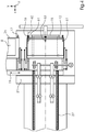
- the first pallet carrier 16 with the pallet 12 still filled with the new panels is brought into an active position with the first pallet carrier 16 facing the pivot arm 23 in alignment with respect to direction x, and the second pallet carrier 17 moves into a passive position on the drive side of the printing machine 1, such as this in Figure 2 is shown.
- the swivel arm 23 takes over the new panels one after the other from the pallet 12 and places them on the belt conveyor 28.
- the carriage 20 with the first and second pallet carriers 16, 17 is moved along the rail 21 in the opposite direction.
- the second pallet carrier 17 with the still empty pallet 26 for the old panels is brought into the active position with the opposite position aligned with the pivot arm 23 with respect to direction x, and the first pallet carrier 16 moves into a passive position on the operating side of the printing machine 1.
- the pivot arm 23 takes over Load the old panels one after the other from the belt conveyor 28 and deposit them on the pallet 26.
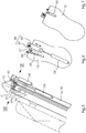
- each pallet 12, 26 has a bolt 53 fastened to it, which can be pivoted about a geometric axis 57 into a locking position and a release position.
- the bolt 53 does not overlap the pressure plates 8.
- the pivoting angle of the bolt 53 to be measured in a plane 56 between the locking position and the release position can be approximately 90 °.
- the bolt 53 engages over the stack of pressure plates 8 in the pallet 12 in order to secure the pressure plates 8 against falling out of this.
- a z. B. on train resilient spring 65 holds the bolt 53 in the locking position.
- the spring 65 acts on a lever 64 which is firmly connected to the bolt 53 and can be pivoted about the axis 57 together with the latter.
- a z. B. pneumatic working cylinder serves as an actuator 54 for pivoting the bolt 53 from the locking position into the release position against the restoring effect of the spring 65.
- the actuator 54 is not attached to the pallet 12, but to another component 55, namely the pallet carrier 16.
- the actuator 54 is coupled to the bolt 54 via a coupling 58.
- the coupling 58 comprises a pin 59 arranged on the lever 64 and a recess 60 arranged on the actuator 54 as coupling halves.
- the pin 59 is inserted into the recess 60.
- the pin 59 is located on a first arm of the lever 64 and the spring 65 engages a second arm of the lever 64.
- the preferably U-shaped recess 60 is made in the piston rod or a piston rod extension of the actuating drive 54 and is open in the coupling direction - transversely to the actuating direction of the actuating drive 54 indicated by a double arrow.
- An interchanged arrangement of pin 59 and recess 60 is also possible.
- the spring 65 always holds the bolt 53 in the locking position when the pallet 12 is not inserted into the pallet carrier 16 and z. B. is transported by the floor conveyor 11 or the pallet lift 13, so that the pressure plates 8 are secured in the pallet 12 during this transport.
- the bolt 53 When the pallet 12 is in the pallet carrier 16 in order to unload the pressure plates 8 from the pallet 12 (new plates) or load them onto the pallet 12 (old plates), the bolt 53, in cooperation with clamps 61, secures the pressure plates 8 in the pallet 12.
- the bolt 53 is periodically pivoted back and forth between the release position and the locking position in the working cycle of the pivot arm 23 (loading or unloading cycle).
- the terminals 61 are temporarily or periodically in their in Figure 5 with the clamping position shown in full line when the bolt 53 is in its release position.
- a release position of the terminals 61 is in Figure 5 shown with phantom line.
- Each terminal 61 is connected to an actuator 66, e.g. B. a pneumatic working cylinder.
- the actuators 66 pivot the clamps 61 about a geometric axis 63 and thereby in a plane 62 which is the image plane of Figure 5 is.
Landscapes
- Sheets, Magazines, And Separation Thereof (AREA)
- Discharge By Other Means (AREA)
- Feeding Of Articles By Means Other Than Belts Or Rollers (AREA)
- Inking, Control Or Cleaning Of Printing Machines (AREA)
- Separation, Sorting, Adjustment, Or Bending Of Sheets To Be Conveyed (AREA)
- Delivering By Means Of Belts And Rollers (AREA)
- Supply, Installation And Extraction Of Printed Sheets Or Plates (AREA)
Priority Applications (1)
| Application Number | Priority Date | Filing Date | Title |
|---|---|---|---|
| CN202110011205.XA CN113147173B (zh) | 2020-01-20 | 2021-01-06 | 用于在印刷机上操纵印刷版的设备 |
Applications Claiming Priority (1)
| Application Number | Priority Date | Filing Date | Title |
|---|---|---|---|
| DE102020101160 | 2020-01-20 |
Publications (2)
| Publication Number | Publication Date |
|---|---|
| EP3851280A1 true EP3851280A1 (fr) | 2021-07-21 |
| EP3851280B1 EP3851280B1 (fr) | 2023-08-09 |
Family
ID=71103289
Family Applications (3)
| Application Number | Title | Priority Date | Filing Date |
|---|---|---|---|
| EP20180239.4A Active EP3851280B1 (fr) | 2020-01-20 | 2020-06-16 | Dispositif de manipulation de plaques d'impression sur une machine d'impression |
| EP20180236.0A Active EP3851279B1 (fr) | 2020-01-20 | 2020-06-16 | Dispositif de manipulation des plaques d'impression sur une machine d'impression |
| EP20180242.8A Active EP3851281B1 (fr) | 2020-01-20 | 2020-06-16 | Dispositif de manipulation de plaques d'impression sur une machine d'impression |
Family Applications After (2)
| Application Number | Title | Priority Date | Filing Date |
|---|---|---|---|
| EP20180236.0A Active EP3851279B1 (fr) | 2020-01-20 | 2020-06-16 | Dispositif de manipulation des plaques d'impression sur une machine d'impression |
| EP20180242.8A Active EP3851281B1 (fr) | 2020-01-20 | 2020-06-16 | Dispositif de manipulation de plaques d'impression sur une machine d'impression |
Country Status (3)
| Country | Link |
|---|---|
| EP (3) | EP3851280B1 (fr) |
| CN (8) | CN113135034B (fr) |
| DE (5) | DE102020207420A1 (fr) |
Families Citing this family (2)
| Publication number | Priority date | Publication date | Assignee | Title |
|---|---|---|---|---|
| DE102021122827A1 (de) | 2021-09-03 | 2023-03-09 | Koenig & Bauer Ag | Vorrichtung und Verfahren zum Zuführen von Druckplatten zu einem Plattenzylinder |
| DE102022109489A1 (de) | 2022-04-20 | 2023-10-26 | Koenig & Bauer Ag | Bogenoffsetrotationsdruckmaschine in Aggregatbauweise |
Citations (5)
| Publication number | Priority date | Publication date | Assignee | Title |
|---|---|---|---|---|
| DE29822104U1 (de) * | 1998-12-14 | 1999-02-18 | AGRAMA Logistik+Materialfluß-Technik GmbH & Co. KG, 86167 Augsburg | Transportvorrichtung für eine Druckmaschine |
| DE202009016761U1 (de) * | 2009-12-11 | 2010-04-08 | Agrama Materialflusstechnik Gmbh & Co. Kg | Transporteinrichtung für Druckplatten |
| DE102008043844A1 (de) * | 2008-11-19 | 2010-05-27 | Koenig & Bauer Aktiengesellschaft | Vorrichtung zum Transport von Druckformen |
| DE102009039050A1 (de) | 2009-08-28 | 2011-03-10 | Manroland Ag | Rollenrotationsdruckmaschine |
| DE102012202533B3 (de) * | 2012-02-20 | 2013-06-20 | Koenig & Bauer Aktiengesellschaft | Verfahren, Vorrichtung und System zur Bereitstellung eines Satzes von in einer Druckmaschine neu aufzulegender Druckformen |
Family Cites Families (48)
| Publication number | Priority date | Publication date | Assignee | Title |
|---|---|---|---|---|
| CH412943A (de) * | 1962-04-28 | 1966-05-15 | Josef Mueller | Vorrichtung zur vollautomatischen Einzelblattabnahme von Papierstapeln mittels Saug- und Blasluft an Druck- und Papierverarbeitungsmaschinen |
| CH677100A5 (fr) | 1988-04-08 | 1991-04-15 | Daverio Ag | |
| DE4130359C2 (de) * | 1991-09-12 | 1997-04-17 | Heidelberger Druckmasch Ag | Vorrichtung zum Ab- und/oder Zuführen von Druckplatten einer Druckmaschine |
| DE4140413C2 (de) * | 1991-12-07 | 1995-03-16 | Roland Man Druckmasch | Vorrichtung zum Wechseln von Druckplatten bei Offsetdruckmaschinen |
| DE4309658C1 (de) * | 1993-03-25 | 1994-10-27 | Roland Man Druckmasch | Vorrichtung zum automatischen Wechseln von Druckplatten bei Bogenoffsetdruckmaschinen mit mehreren Druckwerken |
| DE4442265A1 (de) * | 1994-11-28 | 1996-05-30 | Roland Man Druckmasch | Transportsystem zum Transport von Druckformen |
| IT240384Y1 (it) * | 1996-01-17 | 2001-04-02 | Viero Srl | Carro porta-quadro per macchine di stampa a quadro mobile, consensore di rilevamento della presenza di ostacoli |
| DE19617503A1 (de) * | 1996-05-03 | 1997-11-06 | Ltg Lufttechnische Gmbh | Druckgutfördervorrichtung für Druckwerke von Druckmaschinen |
| US5735384A (en) * | 1996-08-29 | 1998-04-07 | Western Atlas, Inc. | Endless accumulating conveyor |
| ES2218302T3 (es) * | 2000-05-16 | 2004-11-16 | Komori Corporation | Aparato de seguridad para imprenta rotativa. |
| DE10104078A1 (de) * | 2001-01-29 | 2002-08-01 | Heidelberger Druckmasch Ag | Verfahren und Einrichtung zur Vereinzelung von Druckplatten |
| JP2002321840A (ja) * | 2001-04-25 | 2002-11-08 | Fuji Photo Film Co Ltd | 印刷版の枚葉装置 |
| US6776097B2 (en) * | 2002-10-02 | 2004-08-17 | Dainippon Screen Mfg. Co., Ltd. | Plate supplying apparatus |
| US6801302B2 (en) * | 2003-01-06 | 2004-10-05 | Agfa Corporation | Plate registering system and method of operation |
| DE502004004131D1 (de) * | 2003-06-27 | 2007-08-02 | Wolf Verwaltungs Gmbh & Co Kg | Vorrichtung zum Fördern von Stückgut |
| DE10338373A1 (de) * | 2003-08-21 | 2005-03-17 | Koenig & Bauer Ag | Vorrichtung zum Wechseln von Druckplatten |
| EP1571108B1 (fr) * | 2004-03-04 | 2011-05-11 | FUJIFILM Corporation | Dispositif d'alimentation de plaque d'impression planographiques |
| JP4236186B2 (ja) * | 2004-04-28 | 2009-03-11 | 大日本スクリーン製造株式会社 | 画像記録材料供給装置およびその方法 |
| DE102004022086A1 (de) * | 2004-05-05 | 2005-12-01 | Man Roland Druckmaschinen Ag | Druckmaschine |
| FR2884591B1 (fr) * | 2005-04-15 | 2010-10-08 | Goss Int Montataire Sa | Systeme de securite et presse correspondante |
| US20080295722A1 (en) * | 2007-05-31 | 2008-12-04 | Andrew Gordon D | Method and apparatus for pre-staging printing plates |
| DE102008005798A1 (de) * | 2008-01-24 | 2009-07-30 | Koenig & Bauer Aktiengesellschaft | Druckmaschine mit einer Vorrichtung zum Wechseln von Druckplatten |
| DE102008041846B4 (de) * | 2008-09-05 | 2011-11-17 | Koenig & Bauer Aktiengesellschaft | Druckeinheit einer Druckmaschine mit mindestens zwei relativ zueinander positionsveränderbaren Gestellteilen |
| DE102008044111A1 (de) * | 2008-11-27 | 2010-06-02 | Koenig & Bauer Aktiengesellschaft | Bogenanleger mit mindestens einem Tragluftbläser |
| US8322283B2 (en) * | 2009-01-14 | 2012-12-04 | Koenig & Bauer Aktiengesellschaft | Method for providing printing formes at installation positions on one of a plurality of forme cylinders disposed in a printing press |
| US8316767B2 (en) * | 2009-01-20 | 2012-11-27 | Koenig & Bauer Aktiengesellschaft | Transport system for providing printing formes to a printing unit |
| EP2253566B1 (fr) * | 2009-05-22 | 2013-07-31 | Müller Martini Holding AG | Dispositif de chargement d'une trajectoire de traitement dotée de produits d'impression |
| KR200453602Y1 (ko) * | 2009-09-04 | 2011-05-17 | 씨 선 엠에프지 리미티드 | 인쇄회로기판용 예비부착기의 패널출력장치 |
| DE102009046069A1 (de) * | 2009-10-28 | 2011-05-12 | Manroland Ag | Fördersystem für eine Rotationsdruckmaschine |
| EP2338683B1 (fr) | 2009-12-23 | 2012-12-05 | WIFAG Maschinenfabrik AG | Revolver à plaques |
| DE102010011195A1 (de) * | 2010-03-11 | 2011-09-15 | Heidelberger Druckmaschinen Ag | Verfahren und Vorrichtung zur Bereitstellung und Übergabe von Druckplatten |
| DE102010042094B4 (de) * | 2010-10-07 | 2015-11-19 | Koenig & Bauer Ag | Trägerelement zur manuellen und/oder automatischen Beförderung mehrerer Druckformen, Transportsystem in einer Druckerei mit einem Trägerelement sowie Verwendung eines Trägerelementes in einem Transportsystem einer Druckerei |
| DE102010042100A1 (de) * | 2010-10-07 | 2012-04-12 | Koenig & Bauer Aktiengesellschaft | Transportsystem in einer Druckeinheit für den Transport mindestens einer neu auf einem Formzylinder der Druckeinheit aufzubringenden Druckform sowie Druckeinheit mit einem Transportsystem |
| DE102011115777B4 (de) * | 2010-11-12 | 2021-04-22 | Heidelberger Druckmaschinen Ag | Vorrichtung zum Zuführen einer Druckplatte zu einer Bebilderungseinrichtung |
| DE102011116214A1 (de) * | 2010-11-12 | 2012-05-16 | Heidelberger Druckmaschinen Ag | Vorrichtung zum Zuführen einer Druckplatte zu einer Bebilderungseinrichtung |
| DE102010051198A1 (de) * | 2010-11-12 | 2011-03-03 | Heidelberger Druckmaschinen Ag | Vorrichtung zum Zuführen einer Druckplatte zu einer Bebilderungseinrichtung |
| DE102013216664B4 (de) * | 2013-08-22 | 2017-05-18 | Koenig & Bauer Ag | Verfahren zur Durchführung eines Druckformwechsels sowie Druckmaschinen mit einem Druckturm und einer vertikalbeweglichen Speichereinrichtung |
| DE102013216662B4 (de) * | 2013-08-22 | 2017-06-14 | Koenig & Bauer Ag | Verfahren zum Fördern von Druckformen beim Druckformwechsel sowie Druckmaschinen mit einem Druckturm und einer vertikalbeweglichen Speichereinrichtung |
| US9701107B2 (en) * | 2013-08-22 | 2017-07-11 | Koenig & Bauer Ag | Method for changing printing forms and printing machines having a printing tower and a vertically movable storage device |
| US9701105B2 (en) * | 2013-08-22 | 2017-07-11 | Koenig & Bauer Ag | Method for conveying printing forms during the changeover of printing forms and printing machine having a printing tower and a vertically movable storage device |
| CN105564885A (zh) * | 2014-10-08 | 2016-05-11 | 芯发威达电子(上海)有限公司 | 可变角度的输送带装置 |
| US9604787B1 (en) * | 2015-12-09 | 2017-03-28 | Caljan Rite-Hite Aps | Adjustable conveyor systems |
| CN205221752U (zh) * | 2015-12-25 | 2016-05-11 | 安徽银阳光伏科技有限公司 | 一种用于多种规格太阳能电池片的丝网印刷输送装置 |
| ITUB20161142A1 (it) * | 2016-02-29 | 2017-08-29 | Vismunda Srl | Metodo e impianto produttivo automatico per la stampa su celle fotovoltaiche. |
| CN105931364B (zh) * | 2016-04-19 | 2019-02-26 | 广州广电运通金融电子股份有限公司 | 一种分体式票据发放设备及自助金融设备 |
| DE102017210247B4 (de) * | 2017-06-20 | 2023-06-15 | Koenig & Bauer Ag | Bogenanleger für eine Druckmaschine |
| CN109334218B (zh) * | 2018-10-09 | 2024-06-21 | 青州蒙特机械有限公司 | 用于卫星式柔版印刷机的版辊自动更换设备 |
| DE102018220805A1 (de) * | 2018-12-03 | 2019-09-05 | Heidelberger Druckmaschinen Ag | Vorrichtung zum Wechseln von Druckplatten in Druckwerken |
-
2020
- 2020-06-16 DE DE102020207420.8A patent/DE102020207420A1/de active Pending
- 2020-06-16 EP EP20180239.4A patent/EP3851280B1/fr active Active
- 2020-06-16 DE DE102020207418.6A patent/DE102020207418A1/de active Pending
- 2020-06-16 EP EP20180236.0A patent/EP3851279B1/fr active Active
- 2020-06-16 DE DE102020207415.1A patent/DE102020207415A1/de active Pending
- 2020-06-16 DE DE102020207421.6A patent/DE102020207421A1/de active Pending
- 2020-06-16 DE DE102020207419.4A patent/DE102020207419A1/de active Pending
- 2020-06-16 EP EP20180242.8A patent/EP3851281B1/fr active Active
-
2021
- 2021-01-06 CN CN202110011235.0A patent/CN113135034B/zh active Active
- 2021-01-06 CN CN202110011261.3A patent/CN113135035B/zh active Active
- 2021-01-06 CN CN202110011224.2A patent/CN113135033B/zh active Active
- 2021-01-06 CN CN202110011223.8A patent/CN113135032B/zh active Active
- 2021-01-06 CN CN202110011205.XA patent/CN113147173B/zh active Active
- 2021-01-06 CN CN202110011254.3A patent/CN113147174B/zh active Active
- 2021-01-06 CN CN202110011262.8A patent/CN113135036B/zh active Active
- 2021-01-06 CN CN202110011201.1A patent/CN113135031B/zh active Active
Patent Citations (5)
| Publication number | Priority date | Publication date | Assignee | Title |
|---|---|---|---|---|
| DE29822104U1 (de) * | 1998-12-14 | 1999-02-18 | AGRAMA Logistik+Materialfluß-Technik GmbH & Co. KG, 86167 Augsburg | Transportvorrichtung für eine Druckmaschine |
| DE102008043844A1 (de) * | 2008-11-19 | 2010-05-27 | Koenig & Bauer Aktiengesellschaft | Vorrichtung zum Transport von Druckformen |
| DE102009039050A1 (de) | 2009-08-28 | 2011-03-10 | Manroland Ag | Rollenrotationsdruckmaschine |
| DE202009016761U1 (de) * | 2009-12-11 | 2010-04-08 | Agrama Materialflusstechnik Gmbh & Co. Kg | Transporteinrichtung für Druckplatten |
| DE102012202533B3 (de) * | 2012-02-20 | 2013-06-20 | Koenig & Bauer Aktiengesellschaft | Verfahren, Vorrichtung und System zur Bereitstellung eines Satzes von in einer Druckmaschine neu aufzulegender Druckformen |
Also Published As
| Publication number | Publication date |
|---|---|
| CN113135036A (zh) | 2021-07-20 |
| CN113135034A (zh) | 2021-07-20 |
| EP3851280B1 (fr) | 2023-08-09 |
| CN113147173A (zh) | 2021-07-23 |
| CN113135031B (zh) | 2024-07-23 |
| CN113135034B (zh) | 2024-09-17 |
| DE102020207415A1 (de) | 2021-07-22 |
| CN113135035A (zh) | 2021-07-20 |
| CN113147174B (zh) | 2024-07-30 |
| CN113135031A (zh) | 2021-07-20 |
| EP3851281A1 (fr) | 2021-07-21 |
| CN113135036B (zh) | 2024-07-23 |
| CN113135032A (zh) | 2021-07-20 |
| EP3851281B1 (fr) | 2023-08-09 |
| EP3851279B1 (fr) | 2023-08-09 |
| DE102020207419A1 (de) | 2021-07-22 |
| CN113135033A (zh) | 2021-07-20 |
| DE102020207421A1 (de) | 2021-07-22 |
| CN113147173B (zh) | 2024-07-23 |
| DE102020207420A1 (de) | 2021-07-22 |
| CN113147174A (zh) | 2021-07-23 |
| CN113135035B (zh) | 2024-07-23 |
| DE102020207418A1 (de) | 2021-07-22 |
| CN113135033B (zh) | 2025-03-11 |
| EP3851279A1 (fr) | 2021-07-21 |
| CN113135032B (zh) | 2024-07-23 |
Similar Documents
| Publication | Publication Date | Title |
|---|---|---|
| DE102006032204B3 (de) | Verfahren zur Bereitstellung mindestens einer Druckform an ihrem Montageort auf einem Formzylinder einer Rotationsdruckmaschine | |
| EP2072430B1 (fr) | Dispositif de saisie de paquet pour un dispositif de palettisation et procédé de palettisation de paquets | |
| EP0626331B1 (fr) | Procédé et dispositif pour la séparation exacte de la pile principale et de la pile auxiliaire dans les empileurs continus de machines à imprimer les feuilles | |
| DE2547149C3 (de) | Stapelvorrichtung zur Beschickung einer Etagenpresse | |
| EP0470362B1 (fr) | Machine pour traiter des feuilles et dispositif, associé à cette machine, pour transporter des piles de feuilles | |
| DE3613462C2 (fr) | ||
| EP3851280B1 (fr) | Dispositif de manipulation de plaques d'impression sur une machine d'impression | |
| DE102015112625A1 (de) | Verfahren zum Abstapeln von Furnierblättern | |
| DE102022118978A1 (de) | Auslage und Verfahren zum Betreiben einer Auslage mit einem von einem Stapelhubantrieb vertikal verlagerbaren Stapelträger | |
| EP0755784B1 (fr) | Machine d'impression de feuilles | |
| DE102022118979A1 (de) | Auslage und Verfahren zum Betreiben einer Auslage mit einem von einem Stapelhubantrieb vertikal verlagerbaren Stapelträger | |
| DE10049181B4 (de) | Vorrichtung zum Ausschleusen von Probe-und Fehlerbogen aus einer Bogen verarbeitenden Maschine | |
| CH618939A5 (fr) | ||
| EP0511528A1 (fr) | Dispositif pour décharger une machine d'impression de feuilles | |
| DE102006001581B4 (de) | Stapelbrettvorhaltevorrichtung | |
| DE4405586C1 (de) | Vorrichtung zur exakten Trennung eines Hilfsstapels von einem Hauptstapel bei einem Non-Stop-Ausleger in einer bogenverarbeitenden Druckmaschine | |
| DE102020125357B4 (de) | Anleger und Verfahren zum Betrieb eines Anlegers einer bogenverarbeitenden Maschine | |
| DE102009046987B4 (de) | Auslage einer bogenverarbeitenden Maschine mit einem Bogen aufnehmenden Auslagestapel und ein Verfahren zum Stapelwechsel | |
| DE102019133352B4 (de) | Druckplattenlogistiksystem mit einer Plattenbereitstellung | |
| DE10322546A1 (de) | Hilfsstapeleinrichtung im Ausleger einer bogenverarbeitenden Maschine, insbesondere Druckmaschine | |
| DE102007057737A1 (de) | Auslegevorrichtung für bogenverarbeitende Maschinen, insbesondere Druckmaschinen | |
| DE102023119463A1 (de) | Auslage für eine bogenverarbeitende Maschine mit einem von einem Stapelhubantrieb vertikal verlagerbaren Stapelträger | |
| DE102022118980A1 (de) | Auslage und Verfahren zum Betreiben einer Auslage mit einem von einem Stapelhubantrieb vertikal verlagerbaren Stapelträger | |
| DE102009022249B4 (de) | Übergabevorrichtung zur Übergabe eines durch mehrere Blattlagen gebildeten Stapels | |
| DE102020116074A1 (de) | Vorrichtung und Verfahren zum Ablegen und Positionieren eines Stapelbildungshilfsmittels |
Legal Events
| Date | Code | Title | Description |
|---|---|---|---|
| PUAI | Public reference made under article 153(3) epc to a published international application that has entered the european phase |
Free format text: ORIGINAL CODE: 0009012 |
|
| STAA | Information on the status of an ep patent application or granted ep patent |
Free format text: STATUS: THE APPLICATION HAS BEEN PUBLISHED |
|
| AK | Designated contracting states |
Kind code of ref document: A1 Designated state(s): AL AT BE BG CH CY CZ DE DK EE ES FI FR GB GR HR HU IE IS IT LI LT LU LV MC MK MT NL NO PL PT RO RS SE SI SK SM TR |
|
| STAA | Information on the status of an ep patent application or granted ep patent |
Free format text: STATUS: REQUEST FOR EXAMINATION WAS MADE |
|
| 17P | Request for examination filed |
Effective date: 20220121 |
|
| RBV | Designated contracting states (corrected) |
Designated state(s): AL AT BE BG CH CY CZ DE DK EE ES FI FR GB GR HR HU IE IS IT LI LT LU LV MC MK MT NL NO PL PT RO RS SE SI SK SM TR |
|
| GRAP | Despatch of communication of intention to grant a patent |
Free format text: ORIGINAL CODE: EPIDOSNIGR1 |
|
| STAA | Information on the status of an ep patent application or granted ep patent |
Free format text: STATUS: GRANT OF PATENT IS INTENDED |
|
| INTG | Intention to grant announced |
Effective date: 20230413 |
|
| P01 | Opt-out of the competence of the unified patent court (upc) registered |
Effective date: 20230517 |
|
| GRAS | Grant fee paid |
Free format text: ORIGINAL CODE: EPIDOSNIGR3 |
|
| GRAA | (expected) grant |
Free format text: ORIGINAL CODE: 0009210 |
|
| STAA | Information on the status of an ep patent application or granted ep patent |
Free format text: STATUS: THE PATENT HAS BEEN GRANTED |
|
| AK | Designated contracting states |
Kind code of ref document: B1 Designated state(s): AL AT BE BG CH CY CZ DE DK EE ES FI FR GB GR HR HU IE IS IT LI LT LU LV MC MK MT NL NO PL PT RO RS SE SI SK SM TR |
|
| REG | Reference to a national code |
Ref country code: GB Ref legal event code: FG4D Free format text: NOT ENGLISH |
|
| REG | Reference to a national code |
Ref country code: CH Ref legal event code: EP |
|
| REG | Reference to a national code |
Ref country code: DE Ref legal event code: R096 Ref document number: 502020004583 Country of ref document: DE |
|
| REG | Reference to a national code |
Ref country code: IE Ref legal event code: FG4D Free format text: LANGUAGE OF EP DOCUMENT: GERMAN |
|
| REG | Reference to a national code |
Ref country code: LT Ref legal event code: MG9D |
|
| REG | Reference to a national code |
Ref country code: NL Ref legal event code: MP Effective date: 20230809 |
|
| PG25 | Lapsed in a contracting state [announced via postgrant information from national office to epo] |
Ref country code: GR Free format text: LAPSE BECAUSE OF FAILURE TO SUBMIT A TRANSLATION OF THE DESCRIPTION OR TO PAY THE FEE WITHIN THE PRESCRIBED TIME-LIMIT Effective date: 20231110 |
|
| PG25 | Lapsed in a contracting state [announced via postgrant information from national office to epo] |
Ref country code: IS Free format text: LAPSE BECAUSE OF FAILURE TO SUBMIT A TRANSLATION OF THE DESCRIPTION OR TO PAY THE FEE WITHIN THE PRESCRIBED TIME-LIMIT Effective date: 20231209 |
|
| PG25 | Lapsed in a contracting state [announced via postgrant information from national office to epo] |
Ref country code: SE Free format text: LAPSE BECAUSE OF FAILURE TO SUBMIT A TRANSLATION OF THE DESCRIPTION OR TO PAY THE FEE WITHIN THE PRESCRIBED TIME-LIMIT Effective date: 20230809 Ref country code: RS Free format text: LAPSE BECAUSE OF FAILURE TO SUBMIT A TRANSLATION OF THE DESCRIPTION OR TO PAY THE FEE WITHIN THE PRESCRIBED TIME-LIMIT Effective date: 20230809 Ref country code: PT Free format text: LAPSE BECAUSE OF FAILURE TO SUBMIT A TRANSLATION OF THE DESCRIPTION OR TO PAY THE FEE WITHIN THE PRESCRIBED TIME-LIMIT Effective date: 20231211 Ref country code: NO Free format text: LAPSE BECAUSE OF FAILURE TO SUBMIT A TRANSLATION OF THE DESCRIPTION OR TO PAY THE FEE WITHIN THE PRESCRIBED TIME-LIMIT Effective date: 20231109 Ref country code: NL Free format text: LAPSE BECAUSE OF FAILURE TO SUBMIT A TRANSLATION OF THE DESCRIPTION OR TO PAY THE FEE WITHIN THE PRESCRIBED TIME-LIMIT Effective date: 20230809 Ref country code: LV Free format text: LAPSE BECAUSE OF FAILURE TO SUBMIT A TRANSLATION OF THE DESCRIPTION OR TO PAY THE FEE WITHIN THE PRESCRIBED TIME-LIMIT Effective date: 20230809 Ref country code: LT Free format text: LAPSE BECAUSE OF FAILURE TO SUBMIT A TRANSLATION OF THE DESCRIPTION OR TO PAY THE FEE WITHIN THE PRESCRIBED TIME-LIMIT Effective date: 20230809 Ref country code: IS Free format text: LAPSE BECAUSE OF FAILURE TO SUBMIT A TRANSLATION OF THE DESCRIPTION OR TO PAY THE FEE WITHIN THE PRESCRIBED TIME-LIMIT Effective date: 20231209 Ref country code: HR Free format text: LAPSE BECAUSE OF FAILURE TO SUBMIT A TRANSLATION OF THE DESCRIPTION OR TO PAY THE FEE WITHIN THE PRESCRIBED TIME-LIMIT Effective date: 20230809 Ref country code: GR Free format text: LAPSE BECAUSE OF FAILURE TO SUBMIT A TRANSLATION OF THE DESCRIPTION OR TO PAY THE FEE WITHIN THE PRESCRIBED TIME-LIMIT Effective date: 20231110 Ref country code: FI Free format text: LAPSE BECAUSE OF FAILURE TO SUBMIT A TRANSLATION OF THE DESCRIPTION OR TO PAY THE FEE WITHIN THE PRESCRIBED TIME-LIMIT Effective date: 20230809 |
|
| PG25 | Lapsed in a contracting state [announced via postgrant information from national office to epo] |
Ref country code: PL Free format text: LAPSE BECAUSE OF FAILURE TO SUBMIT A TRANSLATION OF THE DESCRIPTION OR TO PAY THE FEE WITHIN THE PRESCRIBED TIME-LIMIT Effective date: 20230809 |
|
| PG25 | Lapsed in a contracting state [announced via postgrant information from national office to epo] |
Ref country code: ES Free format text: LAPSE BECAUSE OF FAILURE TO SUBMIT A TRANSLATION OF THE DESCRIPTION OR TO PAY THE FEE WITHIN THE PRESCRIBED TIME-LIMIT Effective date: 20230809 |
|
| PG25 | Lapsed in a contracting state [announced via postgrant information from national office to epo] |
Ref country code: SM Free format text: LAPSE BECAUSE OF FAILURE TO SUBMIT A TRANSLATION OF THE DESCRIPTION OR TO PAY THE FEE WITHIN THE PRESCRIBED TIME-LIMIT Effective date: 20230809 Ref country code: RO Free format text: LAPSE BECAUSE OF FAILURE TO SUBMIT A TRANSLATION OF THE DESCRIPTION OR TO PAY THE FEE WITHIN THE PRESCRIBED TIME-LIMIT Effective date: 20230809 Ref country code: ES Free format text: LAPSE BECAUSE OF FAILURE TO SUBMIT A TRANSLATION OF THE DESCRIPTION OR TO PAY THE FEE WITHIN THE PRESCRIBED TIME-LIMIT Effective date: 20230809 Ref country code: EE Free format text: LAPSE BECAUSE OF FAILURE TO SUBMIT A TRANSLATION OF THE DESCRIPTION OR TO PAY THE FEE WITHIN THE PRESCRIBED TIME-LIMIT Effective date: 20230809 Ref country code: DK Free format text: LAPSE BECAUSE OF FAILURE TO SUBMIT A TRANSLATION OF THE DESCRIPTION OR TO PAY THE FEE WITHIN THE PRESCRIBED TIME-LIMIT Effective date: 20230809 Ref country code: CZ Free format text: LAPSE BECAUSE OF FAILURE TO SUBMIT A TRANSLATION OF THE DESCRIPTION OR TO PAY THE FEE WITHIN THE PRESCRIBED TIME-LIMIT Effective date: 20230809 Ref country code: SK Free format text: LAPSE BECAUSE OF FAILURE TO SUBMIT A TRANSLATION OF THE DESCRIPTION OR TO PAY THE FEE WITHIN THE PRESCRIBED TIME-LIMIT Effective date: 20230809 |
|
| REG | Reference to a national code |
Ref country code: DE Ref legal event code: R097 Ref document number: 502020004583 Country of ref document: DE |
|
| PG25 | Lapsed in a contracting state [announced via postgrant information from national office to epo] |
Ref country code: IT Free format text: LAPSE BECAUSE OF FAILURE TO SUBMIT A TRANSLATION OF THE DESCRIPTION OR TO PAY THE FEE WITHIN THE PRESCRIBED TIME-LIMIT Effective date: 20230809 |
|
| PLBE | No opposition filed within time limit |
Free format text: ORIGINAL CODE: 0009261 |
|
| STAA | Information on the status of an ep patent application or granted ep patent |
Free format text: STATUS: NO OPPOSITION FILED WITHIN TIME LIMIT |
|
| 26N | No opposition filed |
Effective date: 20240513 |
|
| PG25 | Lapsed in a contracting state [announced via postgrant information from national office to epo] |
Ref country code: SI Free format text: LAPSE BECAUSE OF FAILURE TO SUBMIT A TRANSLATION OF THE DESCRIPTION OR TO PAY THE FEE WITHIN THE PRESCRIBED TIME-LIMIT Effective date: 20230809 |
|
| PG25 | Lapsed in a contracting state [announced via postgrant information from national office to epo] |
Ref country code: BG Free format text: LAPSE BECAUSE OF FAILURE TO SUBMIT A TRANSLATION OF THE DESCRIPTION OR TO PAY THE FEE WITHIN THE PRESCRIBED TIME-LIMIT Effective date: 20230809 |
|
| PG25 | Lapsed in a contracting state [announced via postgrant information from national office to epo] |
Ref country code: BG Free format text: LAPSE BECAUSE OF FAILURE TO SUBMIT A TRANSLATION OF THE DESCRIPTION OR TO PAY THE FEE WITHIN THE PRESCRIBED TIME-LIMIT Effective date: 20230809 |
|
| PG25 | Lapsed in a contracting state [announced via postgrant information from national office to epo] |
Ref country code: MC Free format text: LAPSE BECAUSE OF FAILURE TO SUBMIT A TRANSLATION OF THE DESCRIPTION OR TO PAY THE FEE WITHIN THE PRESCRIBED TIME-LIMIT Effective date: 20230809 |
|
| REG | Reference to a national code |
Ref country code: CH Ref legal event code: PL |
|
| PG25 | Lapsed in a contracting state [announced via postgrant information from national office to epo] |
Ref country code: LU Free format text: LAPSE BECAUSE OF NON-PAYMENT OF DUE FEES Effective date: 20240616 |
|
| PG25 | Lapsed in a contracting state [announced via postgrant information from national office to epo] |
Ref country code: IE Free format text: LAPSE BECAUSE OF NON-PAYMENT OF DUE FEES Effective date: 20240616 |
|
| PG25 | Lapsed in a contracting state [announced via postgrant information from national office to epo] |
Ref country code: BE Free format text: LAPSE BECAUSE OF NON-PAYMENT OF DUE FEES Effective date: 20240630 Ref country code: CH Free format text: LAPSE BECAUSE OF NON-PAYMENT OF DUE FEES Effective date: 20240630 |
|
| REG | Reference to a national code |
Ref country code: BE Ref legal event code: MM Effective date: 20240630 |
|
| PGFP | Annual fee paid to national office [announced via postgrant information from national office to epo] |
Ref country code: DE Payment date: 20250630 Year of fee payment: 6 |
|
| PGFP | Annual fee paid to national office [announced via postgrant information from national office to epo] |
Ref country code: GB Payment date: 20250621 Year of fee payment: 6 |
|
| PGFP | Annual fee paid to national office [announced via postgrant information from national office to epo] |
Ref country code: FR Payment date: 20250617 Year of fee payment: 6 |
|
| PGFP | Annual fee paid to national office [announced via postgrant information from national office to epo] |
Ref country code: AT Payment date: 20250721 Year of fee payment: 5 |
|
| PG25 | Lapsed in a contracting state [announced via postgrant information from national office to epo] |
Ref country code: CY Free format text: LAPSE BECAUSE OF FAILURE TO SUBMIT A TRANSLATION OF THE DESCRIPTION OR TO PAY THE FEE WITHIN THE PRESCRIBED TIME-LIMIT; INVALID AB INITIO Effective date: 20200616 |
|
| PG25 | Lapsed in a contracting state [announced via postgrant information from national office to epo] |
Ref country code: HU Free format text: LAPSE BECAUSE OF FAILURE TO SUBMIT A TRANSLATION OF THE DESCRIPTION OR TO PAY THE FEE WITHIN THE PRESCRIBED TIME-LIMIT; INVALID AB INITIO Effective date: 20200616 |