EP3851608B1 - Verfahren zur erstelllung einer dachabdeckung eines gebäudes - Google Patents
Verfahren zur erstelllung einer dachabdeckung eines gebäudes Download PDFInfo
- Publication number
- EP3851608B1 EP3851608B1 EP21151187.8A EP21151187A EP3851608B1 EP 3851608 B1 EP3851608 B1 EP 3851608B1 EP 21151187 A EP21151187 A EP 21151187A EP 3851608 B1 EP3851608 B1 EP 3851608B1
- Authority
- EP
- European Patent Office
- Prior art keywords
- insulating material
- anchoring
- corrugated plates
- screws
- corrugation
- Prior art date
- Legal status (The legal status is an assumption and is not a legal conclusion. Google has not performed a legal analysis and makes no representation as to the accuracy of the status listed.)
- Active
Links
Images


Classifications
-
- E—FIXED CONSTRUCTIONS
- E04—BUILDING
- E04D—ROOF COVERINGS; SKY-LIGHTS; GUTTERS; ROOF-WORKING TOOLS
- E04D3/00—Roof covering by making use of flat or curved slabs or stiff sheets
- E04D3/36—Connecting; Fastening
- E04D3/3608—Connecting; Fastening for double roof covering or overroofing
-
- E—FIXED CONSTRUCTIONS
- E04—BUILDING
- E04D—ROOF COVERINGS; SKY-LIGHTS; GUTTERS; ROOF-WORKING TOOLS
- E04D12/00—Non-structural supports for roofing materials, e.g. battens, boards
- E04D12/004—Battens
- E04D12/006—Batten-supporting means
-
- E—FIXED CONSTRUCTIONS
- E04—BUILDING
- E04D—ROOF COVERINGS; SKY-LIGHTS; GUTTERS; ROOF-WORKING TOOLS
- E04D13/00—Special arrangements or devices in connection with roof coverings; Protection against birds; Roof drainage ; Sky-lights
- E04D13/16—Insulating devices or arrangements in so far as the roof covering is concerned, e.g. characterised by the material or composition of the roof insulating material or its integration in the roof structure
- E04D13/1606—Insulation of the roof covering characterised by its integration in the roof structure
- E04D13/1643—Insulation of the roof covering characterised by its integration in the roof structure the roof structure being formed by load bearing corrugated sheets, e.g. profiled sheet metal roofs
- E04D13/165—Double skin roofs
-
- E—FIXED CONSTRUCTIONS
- E04—BUILDING
- E04D—ROOF COVERINGS; SKY-LIGHTS; GUTTERS; ROOF-WORKING TOOLS
- E04D3/00—Roof covering by making use of flat or curved slabs or stiff sheets
- E04D3/36—Connecting; Fastening
- E04D3/3601—Connecting; Fastening of roof covering supported by the roof structure with interposition of a insulating layer
- E04D3/3603—Connecting; Fastening of roof covering supported by the roof structure with interposition of a insulating layer the fastening means being screws or nails
Definitions
- the present invention generally relates to the field of building construction and it relates more particularly to a method for producing a roof covering for a building.
- the means of covering are fixed to resistant elements of the building such as a framework or a structural work, which requires being able to insert therein fixing devices of the type of screw, nail, or equivalent. This results in the tedious work of locating the location of the element, drilling the element, installing dowels if necessary and/or other actions.
- a method of production of a roof covering of a building comprising a roof support, in which method a layer of determined thickness of an insulating material having a compressive strength ⁇ 10 ⁇ 50 is fixed to the roof support kPa so as to form an upper face of insulating material, the upper face of the insulating material is covered with bituminous corrugated plates made of cellulose fibers arranged with their respective adjacent edges superimposed, the corrugated plates comprising crests of corrugations separated by corrugation hollows, the corrugated plates are fixed to the insulating material by anchor screws, the anchor screws being positioned to pass through the crests of the corrugations, the anchor screws comprising a shaft with a helical thread, the shaft being surmounted by a head with a diameter greater than the diameter of the barrel excluding the net, and cover elements are installed on the corrugated plates in order to form an external face to
- the corrugated plates and the slats are fixed to an insulating material by special anchoring screws.
- the screws pass through the insulation to attach themselves to more resistant "hard” construction materials, such as those of a frame or another construction structure (wood, metal, masonry, brick, sheet metal, etc.).
- the insulating material which can be in plates or in rolls which are unrolled, is at least a thermal insulator.
- the insulating material may optionally include other functions such as a vapor barrier, for example.
- This insulating material is light, not very compact and has mechanical properties, in particular tear or tensile strength, which are much lower than those of other “hard” building materials.
- the insulating material has a compressive strength at 10% deformation, ⁇ 10, as defined by standard EN 826, of at least 50 kPa.
- the resistance properties of these insulating materials are more specifically described in standard EN 826: 2013 "Thermal insulating products intended for building applications - Determination of behavior in compression”.
- the insulating material typically consists of plates of rock wool, expanded polystyrene (EPS), extruded expanded polystyrene foam (XPS), or polyurethane.
- EPS expanded polystyrene
- XPS extruded expanded polystyrene foam
- polyurethane polyurethane
- the usable insulators have sufficient weight and crushing strength and are therefore of suitable compactness which can possibly be differentiated according to the location on the roof, the geographical area of location of the building as well as the geometric conformation. slopes that make up the roof.
- normal class buildings with little exposure to gusts of wind, urban buildings
- median class buildings that can be exposed to gusts of wind, tall buildings that stand out in the urban context or buildings beyond/outside the urban context
- high class buildings often exposed to gusts of wind, coastal areas, non-urban context, very tall buildings, etc.
- the invention can be implemented with several types of insulation.
- This material can be chosen with a high density p > 140 kg/m 3 and at single density, with a compressive strength ⁇ 10 ⁇ 50 kPa.
- Stone wool for the middle class This material can be chosen with a high density p > 150 kg/m 3 and double density (210/145), with a compressive strength ⁇ 10 ⁇ 50 kPa.
- EPS Extruded polystyrene
- Extruded expanded polystyrene which, for all classes, has a compressive strength o10 > 150 kPa.
- thermal insulation is used whose minimum resistance required for crushing at 10 years is ⁇ 10 ⁇ 50 kPa.
- the anchor screws used here for fixing to the insulating material are specific and are similar to augers or "auger” and they therefore have a diameter of their thread or helix (these two terms being equivalent) very large compared to their diameter. shaft in order to have a large contact surface with the insulating material.
- the anchor screws are made of plastic.
- the slats are fixed via connecting pieces to the insulating material but also to the corrugated plates because the anchoring screws are screwed through the corrugated plates.
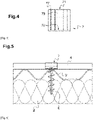
- the building for which the roof is made comprises a roofing support which consists of a masonry shell made of hollow bricks 1 forming a flat surface which is continuous outside the equipment crossing areas (chimney, ventilation, etc.).
- This roof support forms a slope and the roofing produced will also be sloped.
- insulation plates 2 are rigid plates of expanded polystyrene.
- insulation boards should be properly bonded/secured to the underlying structure by means suitable for the underlying structure and the boards.
- the underlying structure and the boards For example, one can use dowels for an underlying brick and cement structure, screws for an underlying wooden structure, adhesive as in the example (avoid sticking with foams because they do not do not comply with European standards) for cement surfaces, wood, tiles, etc.
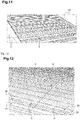
- the layer of insulating material consisting of insulating plates 2 glued to the structural work of hollow bricks 1 forms an upper surface which is also flat and continuous and, figure 11 , we begin to install on this surface corrugated plates 3 of the first type, bituminous in cellulose fibers, starting towards the bottom of the slope.
- These corrugated plates 3 comprise a repeating pattern consisting of a series of three corrugations separated from another series of three corrugations by an extended hollow 31 which is flat.
- Each corrugation has a peak 30 bordered by two depressions 31 and these depressions 31 within a series of three corrugations are narrow and rounded compared to the extended and flat depression 31 separating the series.
- the side edges of the corrugated plates overlap/overlap within a strip of corrugated plates just as for the overlay/the overlap of the end edges along the slope between corrugated plates of two successive strips along the slope, the end of the higher corrugated plate along the slope overlapping that of the lower of the two strips. That's what we see figure 12 for the ends of corrugated plates along the slope between two strips.
- the corrugations are elongated/arranged in the direction of the slope in order to allow the flow of any water that may have found its way onto the corrugated plates.
- anchoring screws 6 arranged along the superposition of the end edges of corrugated plates 3 and making it possible to fix each time two corrugated plates to the insulating plates 2. These anchoring screws 6 are screwed through the corrugated plates 3 at the tops 30 of the corrugations. It should be noted that for all types of corrugated sheets, the anchoring screws are preferably installed on the tops of the corrugations in order to guarantee optimum sealing against liquid water.
- slats 4 are then installed in parallel lines perpendicular to the slope and whose spacing is adapted to the dimensions of the covering elements which are here tiles 5 which will cover the whole.
- the slats 4 are therefore also perpendicular to the undulations.
- the slats 4 are fixed to the insulating plates 2 and to the corrugated plates 3 by anchoring screws 6 via connecting pieces 7.
- the anchor screw is installed lower in the direction of the slope relative to the slat.
- the anchoring screw is installed higher in the direction of the slope relative to the slat and a connecting piece is used which makes it possible to retain the slat by its lateral face on the side opposite the screw in order to prevent the slat from escaping and sliding down the slope.
- the tiles 5 which will be laid have lugs on their underside and the slats 4 allow the tiles 5 to be retained along the slope by their lugs.
- a line of slats is implemented along the bottom of the slope in order to simply raise the tiles of the bottom row in relation to the corrugated sheets and to allow better ventilation between the corrugated sheets and the tiles and avoid that the bottom tile is applied directly to the corrugated plate at the bottom of the slope.
- the connecting piece 7 encloses by its claw 73, 71, 74 partly the slat 4 passing through the top of the latter.
- the connecting piece 7 is placed on a crest 30 of corrugation so that the anchor screw 6 is screwed through the crest 30 of the corrugation and into the layer of insulating material 2 which is below the corrugated plates 3.
- the anchoring screws 6 used to fix the slats 4 via the connecting pieces therefore also serve to complete the fixing of the corrugated plates 3 to the insulating material. From this arrangement, it also follows that the slats 4, via the connecting pieces 7, are also fixed to the corrugated plates 3.
- the anchor 7' with legs and even 7 without legs is relatively stable once placed on the lath and the top of the corrugation.
- the anchor screw for the connecting piece will here be screwed through a superposition of two side edges of two corrugated plates of a row. At other locations along the slat 4, it may be a single corrugated plate which is crossed by the screwing of the anchor screw 6.
- anchoring screws 6 are all screwed at the level of the vertices of the undulations of the corrugated plates and it is therefore possible to use anchoring screws of the same length without the need for anchoring screws of different lengths. If certain anchoring screws had been installed in corrugated hollows, then anchoring screws 6, 8 of different shaft lengths 61, 81 could have been provided for fixing in a hollow or flat (short anchoring screw) and for top fixing (long anchor screw).
- An electric screwdriver 11 is implemented with a TORX ® screwdriver bit because the head 60, 80 of the anchoring screw 6, 8 has a driving recess 64, 84 for screwing (or even unscrewing) TORX ® .
- anchor screws In practice, it is preferred to install the anchor screws at the crests of the corrugations and if anchor screws of different shaft lengths and/or different thread pitches and/or different and therefore different thread diameters are provided types of anchor screws, this is essentially a function of the height of the corrugations and/or the thickness and the nature of the insulating material which are used. Anchor screws can therefore be chosen mainly according to the characteristics of the corrugated plates, the location of the screw (hollow/flat or top) and the insulating material.
- an anchor screw is used, the length of which is adapted to the height of the corrugations and to the thickness of the insulating material so that the anchor screw enters the insulating material well but does not cross it completely and does not does not come out on the other side of the insulating material.
- the measuring meter is intended to position the slat 4 correctly with respect to a previous slat along the slope or with respect to the lower edge of the slope, depending on the dimensions of the tiles.
- the bottom tiles must have their lower edges above the gutter 10 arranged at the edge of the roof.
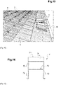
- the tiles 5 can be installed on the slats starting with the bottom row as seen figure 15 .
- anchor screws are used first, before the installation of the slats, to fix the corrugated sheets to the insulating material, and other anchor screws are used secondly to fix the slats , in particular via connecting pieces, to the corrugated plates and, preferably, also to the insulating material.
- This first use of the anchor screws can be carried out to ensure optimal fixing of the corrugated sheets or only to ensure a minimal fixing, less than the optimal fixing, during the realization of the roofing, the second use of the anchor screws allowing to achieve the optimum fixing of the corrugated sheets.
- the optimum fixing corresponds to a degree of fixing which allows the roof to resist tearing or destruction, in particular due to the wind, with regard more particularly to corrugated sheets.
- the fastening of the corrugated sheets should preferably be optimal. It should be noted that the weight and type of roofing elements can also influence the degree of fixing since these elements apply a certain weight to the slats and corrugated sheets.
- bituminous corrugated plates made of cellulose fibers having other corrugation patterns and for example with regular corrugations (not separated by flats) or not, in particular the one 3" from the figure 7 which we will present later in more detail.
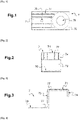
- the figures 1 to 4 represent a single connecting piece 7 (without side legs) intended to be installed to press the slat 4 against the corrugated plate 3, 3', 3" and making it possible to fix the slat 4 to the corrugated plate 3, 3', 3" and the insulating material 2.
- the connecting piece 7 is formed of several parts: a plate 70 and a retaining claw 71, 73, 74 of the slat. We will see in relation to the figures 16 to 18 that it is also possible to implement connecting pieces 7' further comprising two lateral tabs 72.
- the connecting piece 7, 7' is metallic.
- the plate 70 which is flat and here square in shape is intended to be placed flat on a corrugation top 30 of the corrugated plate 3, 3', 3", the connecting piece 7, 7' being installed on a top
- a crossing hole 78 is made in the center of the plate 70 in order to allow the passage of an anchor screw shaft 6, 8 without the thread of the screw having to force or widen the passage orifice 78 when screwing in the anchor screw but, preferably, preventing the screw from being extracted through the passage orifice 78 by simple axial traction.
- the passage orifice 78 has a diameter equal to approximately 3/4 of the width of the thread 62, 82 of the anchor screw, this to allow a better mesh between the anchor screw and the plate 70. A greater coupling between the anchor screw and the plate 70 is thus implemented to take account of the mechanical properties of the insulation.
- the retaining claw 73, 71, 74 of the slat is continuous with one side of the plate 70 which is in relation with the top 30 of the corrugation.
- the retaining claw 73, 71, 74 which is in several portions at least partially encloses the slat 4 and, in this example, encloses its upper face by a portion 71, one of the two side faces over its entire height by a portion 73 and the other side face over part of its height by a portion 74.
- the slat is directly applied against the top of the undulations by the retaining claw 73, 71, 74 of the connecting piece 7.
- slats 4 made of plastic, preferably perforated metal, wood and having different dimensions, the connecting piece 7, 7' used being adapted to the slat.
- metal slats 4 the metals of the slats 4 and of the connecting pieces 7, 7' are chosen for their compatibility and, in particular, to avoid oxidation-reduction reactions between them.
- the side tabs 72 are either vertical ( figure 16 and 17 ) or angled downwards and outwards ( figure 18 ), the lower ends of the lateral tabs 72 being rounded and being intended to bear against the upper face of the corrugated plate 3, 3', 3", on either side of a vertex, the connecting piece straddling the top 30 of the undulation.
- the inclination of the lateral legs with respect to the plate 70 is adapted to the shape and dimensions of the undulations: on the figure 16 and 17 , the side tabs 72 of the connecting piece 7' are vertical and perpendicular to the plate 70, figure 18 the side tabs 72 of the connecting piece 7' gradually move apart from one another going downwards.
- the inclination of the side tabs 72 can be adjusted by forcing or twisting the metal of the connecting piece 7'.
- ribs 77 obtained in particular by stamping. These ribs can also be made on the connecting pieces 7' with side tabs 72.
- the connecting piece 7, 7' is made of metal, for example stainless steel, galvanized steel, and is obtained by cutting a blank from a metal plate and this blank is then bent to form the different parts: plate 70 , claw 73, 71, 74 for retaining the slat and any lugs 72.
- the metal thickness is between 1 mm and 1.5 mm and is preferably 1.2 mm. Since the slats 4 generally have standardized dimensions, it is possible to provide for the production of two models of connecting pieces allowing adaptation to most of the dimensions encountered for slats and which are 3x3 cm, 3x2 cm and 3x4 cm.
- a hole 79 has been provided through the portion 71 of the claw of the connecting piece 7 on the figure 1 to 4 .
- the hole 79 is omitted.
- the hole 79 can also be made on the connecting pieces 7' with side tabs 72.
- part of the portion 71 of the claw and it is bent downwards and it serves as a point for nailing the claw to the slat: the installer places the claw on the slat and strikes the claw with a mallet so that the point of the V sinks into the latte.
- corrugated plates differ in particular by the presence or not of flats and the number of undulations/waves between two flats.
- the corrugated plate 3 of the first type of the figure 6 or the figure 17 comprises series of three undulations and a flat hollow, each undulation being of a width allowing the use of a connecting piece 7′ with vertical tabs 72 in the event that they are implemented.
- the 3' corrugated plate of the second type of the figure 5 or the figure 18 has series of two undulations separated by a flat hollow.
- Each corrugation of the corrugated plate 3' being wider than that of the corrugated plate of the first type 3, a connecting piece 7' with lateral tabs 72 inclined with respect to the vertical is then used if connecting pieces 7' with tab sides are used.
- the 3" corrugated plate of the third type of the figure 7 has regular waves and does not have a flat.
- Anchor screws of different lengths are shown figures 8 and 9 .
- On the figure 9 is shown a short anchor screw 6 with shaft 61 shorter than the long anchor screw 8, figure 8 , with barrel 81 longer.
- the anchor screws 6, 8 have heads 60, 80 at an upper end and spikes 63, 83 at a lower end.
- the points 63, 83 of the lower ends of the anchor screws are pointed and of the self-piercing type like a nail.
- a helical thread 62, 82 is arranged along the shaft 61, 81.
- Two lengths of anchor screws can be used for a given realization if it is planned to fix the corrugated plates to the insulating material by screwing short anchor screws at the level of the hollows, possibly flats, corrugations and by screwing in screws d long anchorage at the tops of undulations for fixing the slats and/or simply fixing the corrugated sheets to the insulating material.
- anchor screws of the same length for the fixings in the depressions/flats and for the fixings at the tops of the corrugations. If all anchor screw fixings are made, as is preferred, on the tops of the corrugations, the length of the anchor screw with a long or short shaft is chosen according to the height of the corrugations and the thickness of the insulating material, all the anchoring screws then being of the same length.
- anchoring screws of different lengths can be provided.
- two lengths of anchor screws are provided with short anchor screws and long anchor screws.
- the length of the anchor screw is chosen according to the dimensional characteristics of the corrugated sheets, the place where the anchor screw is installed (on a peak or in a hollow or flat) and the thickness of the insulation boards.
- the anchoring screws of the slats also enter the insulating material because this ensures an additional fixing of the corrugated plate to the insulating material.
- the lengths (or heights depending on the point of view) of the two anchor screws 6, 8 are on the other hand different, the shorter 6 measures 95 mm in length/height with 5 turns for the net and the longest 8 is 125 mm in length/height with 7 turns for the net.
- a 95 mm long/height screw can be used and with an insulating panel thicker than 120 mm, a 125 mm long/height screw can be used.
- Anchor screws are produced by industrial hot stamping or casting, and they can be made of nylon or polypropylene polymer or their derivatives.
- a connecting piece 7, 7' is implemented to fix the slats to the corrugated plates and to the insulating material, the anchoring screws being arranged laterally to the slats.
- the anchoring screws can pass through the slats and/or if the anchoring screw is arranged lateral to the slat, the head 60, 80 of the screw anchor which is relatively wide can be applied by a part of its lower face on the upper face of the slat to press it against the top of the corrugated plate.
- a large diameter washer can be provided at the underhead of the anchoring screw which bears against the upper face of the slat. This washer can be replaced by a flat pierced plate resting on the upper face of the slat.
- the slats and recesses can be dimensioned so that the upper surface of the slat installed in the recess is substantially level with the top of the corrugation and the retaining claw of the connecting piece can then be adapted to be a simple finger in the same plane as the plate 70, the finger resting on the upper face of the slat 4 which is in the recess, the latter 4 being then enclosed, downwards and on the upstream and downstream sides (in the direction of the slope, the upstream being towards the high side of the slope), by the recess and, upwards, by the finger constituting the claw of the connecting piece.
Landscapes
- Engineering & Computer Science (AREA)
- Architecture (AREA)
- Civil Engineering (AREA)
- Structural Engineering (AREA)
- Mechanical Engineering (AREA)
- Roof Covering Using Slabs Or Stiff Sheets (AREA)
- Organic Low-Molecular-Weight Compounds And Preparation Thereof (AREA)
- Conveying And Assembling Of Building Elements In Situ (AREA)
Claims (10)
- Verfahren zur Erstellung einer Dachabdeckung eines Gebäudes, wobei das Gebäude einen Dachstuhl (1) aufweist, wobei man bei dem Verfahren- auf dem Dachstuhl (1) eine Schicht Isoliermaterial (2) einer bestimmten Dicke so befestigt, daß eine Oberseite des Isoliermaterials (2) gebildet wird,
dadurch gekennzeichnet, daß das Isoliermaterial einen Kompressionswiderstand σ10 ≥ 50 kPa aufweist,- die Oberseite des Isoliermaterials (2) mit gewellten, mit Bitumen versehenen Platten (3, 3', 3") aus Zellulosefasern mit Überdeckung der jeweilig aneinander angrenzenden Ränder bedeckt, wobei die gewellten Platten (3, 3', 3") durch Wellentäler (31) getrennte Wellenspitzen (30) aufweisen,- die gewellten Platten (3, 3', 3") mit Verankerungsschrauben (6, 8) auf dem Isoliermaterial (2) befestigt, wobei die Verankerungsschrauben (6, 8) so angeordnet werden, daß sie durch die Wellenspitzen (30) gehen, wobei die Verankerungsschrauben (6, 8) einen Schaft (61, 81) mit einem schneckenförmigen Gewinde (62, 82) aufweisen, wobei der Schaft (61, 81) von einem Kopf (60, 80) mit einem größeren Durchmesser als dem des Schafts ohne Gewinde überragt wird, und- auf den gewellten Platten (3, 3', 3") Dachdeckelemente (5) installiert, um eine Außenseite der Abdeckung zu bilden. - Verfahren gemäß Anspruch 1, dadurch gekennzeichnet, daß die Dachdeckelemente (5) auf den gewellten Platten (3, 3', 3") mittels Latten (4) installiert werden, wobei das Verfahren dann darin besteht, daß- man auf dem Dachstuhl (1) die Schicht Isoliermaterial (2) bestimmter Dicke, das einen Kompressionswiderstand σ10 ≥ 50 kPa aufweist, befestigt, um so die Oberseite des Isoliermaterials (2) zu bilden,- man die Oberseite des Isoliermaterials (2) mit den gewellten, mit Bitumen versehenen Platten (3, 3', 3") aus Zellulosefasern mit Überdeckung der jeweilig aneinander angrenzenden Ränder bedeckt, wobei die gewellten Platten (3, 3', 3") durch Wellentäler (31) voneinander getrennte Wellenspitzen (30) aufweisen,- man die gewellten Platten (3, 3', 3") auf dem Isoliermaterial (2) mittels der Verankerungsschrauben (6, 8) befestigt, wobei die Verankerungsschrauben (6, 8) so angeordnet werden, daß sie die Wellenspitzen (30) durchdringen, wobei die Verankerungsschrauben (6, 8) einen Schaft (61, 81) mit einem schneckenförmigen Gewinde (62, 82) aufweisen, wobei der Schaft (61, 81) von einem Kopf (60, 80) mit einem größeren Durchmesser als dem Durchmesser des Schafts ohne Gewinde überragt wird,- man auf den gewellten Platten (3, 3', 3") die Latten (4) installiert, wobei die Latten (4) entlang zueinander paralleler und zu den Wellen senkrechter Linien angeordnet werden, damit jede Latte (4) auf den Wellenspitzen (30) ruht,- man die Latten (4) mindestens an den gewellten Platten (3, 3', 3") mittels der Verankerungsschrauben (6, 8) befestigt, wobei die Verankerungsschrauben (6, 8) so angeordnet werden, daß sie die Wellenspitzen (30) durchdringen,- man die Dachdeckelemente (5) auf den Latten (4) installiert, um die Außenseite der Dachabdeckung zu bilden.
- Verfahren gemäß Anspruch 2, dadurch gekennzeichnet, daß die Latten (4) mindestens an den gewellten Platten (3, 3', 3") mittels an den Wellenspitzen (30) angeordneter Verbindungsstücke (7, 7') befestigt werden, wobei das Verbindungsstück (7, 7') eine Lattenrückhaltekralle (73, 71, 74) und eine Platte (70) aufweist, wobei die Platte (70) flach auf die Wellenspitze (30) gelegt wird, wobei die Lattenrückhaltekralle (73, 71, 74) mit einem auf der Seite der Wellenspitze gelegenen Ende der Platte (70) verbunden wird, wobei die Lattenrückhaltekralle (3, 3', 3") das Rückhalten der Latte (4) an der Wellenspitze (30) ermöglicht, wobei die Platte (70) ein Durchgangsloch (78) für die Verankerungsschraube (6, 8) aufweist, wobei der Schaft (61, 81) und das Gewinde (62, 82) der Verankerungsschraube (6, 8) die Platte (70) und die Wellenspitze (30) der gewellten Platte (3, 3', 3") durchdringen, wobei der Kopf (60, 80) der Verankerungsschraube (6, 8) an der Oberseite de Platte (70) anliegt.
- Verfahren gemäß Anspruch 3, dadurch gekennzeichnet, daß das Verbindungsstück (7') außerdem zwei seitliche Zungen (72) aufweist und daß die beiden seitlichen Zungen (72) auf jeder Seite der Wellenspitze (30) nach unten gerichtet sind und mit deren unteren Enden beiderseits der Spitze (30) auf der gewellten Platte (3, 3', 3") aufliegen, wobei das Verbindungsstück (7') rittlings auf der Wellenspitze (30) angeordnet ist.
- Verfahren gemäß einem der Ansprüche 2 bis 4, dadurch gekennzeichnet, daß die Verankerungsschrauben (6, 8) außerdem die Befestigung der Latten (4) am Isoliermaterial (2) ermöglichen.
- Verfahren gemäß einem der Ansprüche 1 bis 5, dadurch gekennzeichnet, daß die Verankerungsschrauben (6, 8) aus einem Plastikmaterial sind und daß der Kopf (60, 80) der Verankerungsschraube (6, 8) kreisrund mit einem Durchmesser von 30 mm ist und eine zentrale Antriebsvertiefung (64, 68) aufweist, der Schaft (61, 81) der Verankerungsschraube einen kegelstumpfförmigen oberen Teil, einen zylindrischen mittleren Teil mit einem Durchmesser von 6 mm und einen selbstbohrenden unteren Teil mit spitzem Ende (63, 83) aufweist und das Gewinde (82) der Verankerungsschraube einen Gewindegang von 16 mm und einen Durchmesser über alles von 22 mm hat.
- Verfahren gemäß einem der Ansprüche 1 bis 6, dadurch gekennzeichnet, daß die Verankerungsschrauben (6, 8) zweierlei Typs sind, und zwar kurze, 95 mm lange Verankerungsschrauben (6) und lange, 125 mm lange Verankerungsschrauben (8).
- Verfahren gemäß einem der Ansprüche 1 bis 7, dadurch gekennzeichnet, daß das Dach schräg ist und die Dachdeckelemente (5) Dachziegel sind und daß man, falls Dachziegel verwendet werden, die an deren Unterseite Rückhaltenasen aufweisen, Latten (4) auf den gewellten Platten (3, 3', 3") installiert, damit die Dachziegel durch deren Nasen an den Latten (4) zurückgehalten werden.
- Verfahren gemäß einem der Ansprüche 1 bis 8, dadurch gekennzeichnet, daß der Dachstuhl (1) eine im Wesentlichen durchgängige obere Bauwerksoberfläche aufweist, die das Bauwerk nach oben hin abschließt, und das Isoliermaterial (2) auf der Bauwerksoberfläche durch Klebung (12) befestigt wird.
- Verfahren gemäß einem der Ansprüche 1 bis 9, dadurch gekennzeichnet, daß man Verankerungsschrauben verwendet, die einen hohlen Schaft aufweisen, der ein Einspritzen von Klebematerial in das Isoliermaterial ermöglicht, um die Verankerungsschraube am Isoliermaterial festzukleben, sobald die Verankerungsschraube ins Isoliermaterial geschraubt ist.
Applications Claiming Priority (1)
| Application Number | Priority Date | Filing Date | Title |
|---|---|---|---|
| FR2000442A FR3106351B1 (fr) | 2020-01-17 | 2020-01-17 | Procédé de réalisation d’une couverture de toiture d’un bâtiment et ensemble d’éléments adaptés. |
Publications (3)
| Publication Number | Publication Date |
|---|---|
| EP3851608A2 EP3851608A2 (de) | 2021-07-21 |
| EP3851608A3 EP3851608A3 (de) | 2021-09-22 |
| EP3851608B1 true EP3851608B1 (de) | 2022-10-05 |
Family
ID=70228219
Family Applications (1)
| Application Number | Title | Priority Date | Filing Date |
|---|---|---|---|
| EP21151187.8A Active EP3851608B1 (de) | 2020-01-17 | 2021-01-12 | Verfahren zur erstelllung einer dachabdeckung eines gebäudes |
Country Status (3)
| Country | Link |
|---|---|
| EP (1) | EP3851608B1 (de) |
| ES (1) | ES2931048T3 (de) |
| FR (1) | FR3106351B1 (de) |
Families Citing this family (1)
| Publication number | Priority date | Publication date | Assignee | Title |
|---|---|---|---|---|
| CN114687756B (zh) * | 2022-03-15 | 2025-11-28 | 中国铁道科学研究院集团有限公司铁道建筑研究所 | 一种铁路隧道用玄武岩波纹板及其制备方法 |
Family Cites Families (13)
| Publication number | Priority date | Publication date | Assignee | Title |
|---|---|---|---|---|
| FR2496551B1 (fr) * | 1980-12-19 | 1988-01-29 | Omnium Fs Indl Cal | Machine a profiler des materiaux souples avec ou sans alternances predeterminees d'ondes et de zones plates, et materiaux ainsi obtenus |
| GB2092202B (en) * | 1981-01-29 | 1985-02-13 | Itw Ltd | Overroofing of buildings |
| US5692352A (en) * | 1984-01-04 | 1997-12-02 | Harold Simpson, Inc. | Roof panel standing seam assemblies |
| AT380732B (de) * | 1984-12-21 | 1986-06-25 | Sfs Stadler Ag | Schraube zur befestigung von aus profilierten platten und darunter angeordneter isolierschicht bestehenden dach- oder wandverkleidungselementen an einem festen unterbau |
| DE3515419C1 (de) * | 1985-04-29 | 1986-08-14 | Walter Dipl.-Ing. 4630 Bochum Holzapfel | Abstandhalter zur Distanzierung einer unter einer Dachabdeckung vorhandenen Dachunterkonstruktion von der tragenden Dachkonstruktion |
| US4892429A (en) | 1987-08-03 | 1990-01-09 | Giannuzzi Louis | Roof anchor and stress plate assembly |
| US4763456A (en) | 1987-08-03 | 1988-08-16 | Giannuzzi Louis | Roof anchor and stress plate assembly |
| FR2637633B1 (fr) * | 1988-10-12 | 1993-04-16 | Omnium Francais Indl Cal | Toit en tuiles plates, son procede de realisation, et element de support et repartition de charge pour un tel toit |
| DE9407875U1 (de) * | 1994-05-16 | 1994-07-07 | Windsheimer, Hans, 91583 Schillingsfürst | Befestigungselement |
| FR2755712B1 (fr) | 1996-11-12 | 1999-08-06 | Onduline Sa | Materiau de couverture |
| DE20111194U1 (de) | 2001-07-05 | 2001-09-20 | EJOT Verbindungstechnik GmbH & Co. KG, 57334 Bad Laasphe | Schraube zum Eindrehen in einen Werkstoff niederer Festigkeit |
| EP1645698A1 (de) * | 2004-10-05 | 2006-04-12 | Rockwool International A/S | Eine Dachkonstruktion |
| US8677718B2 (en) * | 2011-05-02 | 2014-03-25 | Joseph T. Marshall | Retrofit mounting clip for an exterior building surface |
-
2020
- 2020-01-17 FR FR2000442A patent/FR3106351B1/fr active Active
-
2021
- 2021-01-12 ES ES21151187T patent/ES2931048T3/es active Active
- 2021-01-12 EP EP21151187.8A patent/EP3851608B1/de active Active
Also Published As
| Publication number | Publication date |
|---|---|
| ES2931048T3 (es) | 2022-12-23 |
| FR3106351B1 (fr) | 2022-04-01 |
| EP3851608A2 (de) | 2021-07-21 |
| FR3106351A1 (fr) | 2021-07-23 |
| EP3851608A3 (de) | 2021-09-22 |
Similar Documents
| Publication | Publication Date | Title |
|---|---|---|
| FR2466581A1 (fr) | Latte pour toiture | |
| EP2137769B1 (de) | Struktur zur montage von rahmen zur aufnahme von paneele, z.b. photovoltaischer paneele, an gebäudewänden | |
| US10473134B2 (en) | Enlarged head fastener device and method of manufacture | |
| EP3851608B1 (de) | Verfahren zur erstelllung einer dachabdeckung eines gebäudes | |
| CA2947707C (en) | Compression indentation fastener device | |
| CA2409410A1 (fr) | Dispositif d'assemblage des bords longitudinaux de panneaux, lattes ou lambris, a repartition de forces | |
| US20240209634A1 (en) | Tile and support structure | |
| EP0399874B1 (de) | Lattenvorrichtung, insbesondere für Überdeckung von geneigten Dächern | |
| EP2646628A1 (de) | Element mit einer tragefläche zur aufnahme einer fassadenplatte, insbesondere einer gipsbauplatte | |
| FR2524524A1 (fr) | Procede et dispositif de fixation d'une couverture isolante sur une toiture de batiment et assemblage en resultant | |
| EP2644798B1 (de) | Bitumenimprägniertes geformtes Firstband aus Zellulose, und Anwendung | |
| FR3041835A1 (fr) | Mecanisme de fixation de panneaux solaires sur des plaques metalliques formant un toit. | |
| FR2541709A1 (fr) | Procedes et bacs autoportants pour la construction de toitures en tuiles rondes, toitures et batiments obtenus | |
| EP2489809B1 (de) | Verfahren zur Herstellung eines Strukturelements, und so hergestellte Elemente | |
| FR2542786A1 (fr) | Element de toiture ou de facade | |
| FR2680816A1 (fr) | Couverture etanche de batiment et son procede de pose. | |
| EP1496169B1 (de) | Herstellungsverfahren für ein Dach mit Hohlziegeln und solch ein Dach | |
| WO2019135170A1 (fr) | Construction anticyclonique comportant un toit résistant aux vents violents | |
| US20100251650A1 (en) | Simulated shingle structure | |
| JP4804859B2 (ja) | 棟瓦施工法 | |
| EP3366858B1 (de) | Flachziegel für eine dacheindeckung eines gebäudes, der eine verstärkte abdichtung umfasst | |
| EP1707703A1 (de) | Holzschindel | |
| EP0444371A1 (de) | Stütz- und Lastverteilungselement für mit flachen Ziegeln bedecktes Dach, und dieses Element enthaltendes Dach | |
| JP2009287368A (ja) | 機械的固定法による断熱防水構造及び工法 | |
| BE1018203A3 (fr) | Crochet d'ancrage pour toiture. |
Legal Events
| Date | Code | Title | Description |
|---|---|---|---|
| PUAI | Public reference made under article 153(3) epc to a published international application that has entered the european phase |
Free format text: ORIGINAL CODE: 0009012 |
|
| STAA | Information on the status of an ep patent application or granted ep patent |
Free format text: STATUS: THE APPLICATION HAS BEEN PUBLISHED |
|
| AK | Designated contracting states |
Kind code of ref document: A2 Designated state(s): AL AT BE BG CH CY CZ DE DK EE ES FI FR GB GR HR HU IE IS IT LI LT LU LV MC MK MT NL NO PL PT RO RS SE SI SK SM TR |
|
| PUAL | Search report despatched |
Free format text: ORIGINAL CODE: 0009013 |
|
| AK | Designated contracting states |
Kind code of ref document: A3 Designated state(s): AL AT BE BG CH CY CZ DE DK EE ES FI FR GB GR HR HU IE IS IT LI LT LU LV MC MK MT NL NO PL PT RO RS SE SI SK SM TR |
|
| RIC1 | Information provided on ipc code assigned before grant |
Ipc: E04D 13/16 20060101ALI20210816BHEP Ipc: E04D 12/00 20060101ALI20210816BHEP Ipc: E04D 3/36 20060101AFI20210816BHEP |
|
| STAA | Information on the status of an ep patent application or granted ep patent |
Free format text: STATUS: REQUEST FOR EXAMINATION WAS MADE |
|
| 17P | Request for examination filed |
Effective date: 20211013 |
|
| RBV | Designated contracting states (corrected) |
Designated state(s): AL AT BE BG CH CY CZ DE DK EE ES FI FR GB GR HR HU IE IS IT LI LT LU LV MC MK MT NL NO PL PT RO RS SE SI SK SM TR |
|
| RIN1 | Information on inventor provided before grant (corrected) |
Inventor name: TORELLI, DAVIDE Inventor name: STEFANAZZI, ALBERTO Inventor name: LUCCHINI, ANGELO |
|
| GRAP | Despatch of communication of intention to grant a patent |
Free format text: ORIGINAL CODE: EPIDOSNIGR1 |
|
| STAA | Information on the status of an ep patent application or granted ep patent |
Free format text: STATUS: GRANT OF PATENT IS INTENDED |
|
| INTG | Intention to grant announced |
Effective date: 20220518 |
|
| GRAS | Grant fee paid |
Free format text: ORIGINAL CODE: EPIDOSNIGR3 |
|
| GRAA | (expected) grant |
Free format text: ORIGINAL CODE: 0009210 |
|
| STAA | Information on the status of an ep patent application or granted ep patent |
Free format text: STATUS: THE PATENT HAS BEEN GRANTED |
|
| AK | Designated contracting states |
Kind code of ref document: B1 Designated state(s): AL AT BE BG CH CY CZ DE DK EE ES FI FR GB GR HR HU IE IS IT LI LT LU LV MC MK MT NL NO PL PT RO RS SE SI SK SM TR |
|
| REG | Reference to a national code |
Ref country code: GB Ref legal event code: FG4D Free format text: NOT ENGLISH |
|
| REG | Reference to a national code |
Ref country code: CH Ref legal event code: EP |
|
| REG | Reference to a national code |
Ref country code: AT Ref legal event code: REF Ref document number: 1522848 Country of ref document: AT Kind code of ref document: T Effective date: 20221015 |
|
| REG | Reference to a national code |
Ref country code: IE Ref legal event code: FG4D Free format text: LANGUAGE OF EP DOCUMENT: FRENCH |
|
| REG | Reference to a national code |
Ref country code: DE Ref legal event code: R096 Ref document number: 602021000487 Country of ref document: DE |
|
| REG | Reference to a national code |
Ref country code: ES Ref legal event code: FG2A Ref document number: 2931048 Country of ref document: ES Kind code of ref document: T3 Effective date: 20221223 |
|
| REG | Reference to a national code |
Ref country code: LT Ref legal event code: MG9D |
|
| REG | Reference to a national code |
Ref country code: NL Ref legal event code: MP Effective date: 20221005 |
|
| REG | Reference to a national code |
Ref country code: AT Ref legal event code: MK05 Ref document number: 1522848 Country of ref document: AT Kind code of ref document: T Effective date: 20221005 |
|
| PG25 | Lapsed in a contracting state [announced via postgrant information from national office to epo] |
Ref country code: NL Free format text: LAPSE BECAUSE OF FAILURE TO SUBMIT A TRANSLATION OF THE DESCRIPTION OR TO PAY THE FEE WITHIN THE PRESCRIBED TIME-LIMIT Effective date: 20221005 |
|
| PG25 | Lapsed in a contracting state [announced via postgrant information from national office to epo] |
Ref country code: SE Free format text: LAPSE BECAUSE OF FAILURE TO SUBMIT A TRANSLATION OF THE DESCRIPTION OR TO PAY THE FEE WITHIN THE PRESCRIBED TIME-LIMIT Effective date: 20221005 Ref country code: PT Free format text: LAPSE BECAUSE OF FAILURE TO SUBMIT A TRANSLATION OF THE DESCRIPTION OR TO PAY THE FEE WITHIN THE PRESCRIBED TIME-LIMIT Effective date: 20230206 Ref country code: NO Free format text: LAPSE BECAUSE OF FAILURE TO SUBMIT A TRANSLATION OF THE DESCRIPTION OR TO PAY THE FEE WITHIN THE PRESCRIBED TIME-LIMIT Effective date: 20230105 Ref country code: LT Free format text: LAPSE BECAUSE OF FAILURE TO SUBMIT A TRANSLATION OF THE DESCRIPTION OR TO PAY THE FEE WITHIN THE PRESCRIBED TIME-LIMIT Effective date: 20221005 Ref country code: FI Free format text: LAPSE BECAUSE OF FAILURE TO SUBMIT A TRANSLATION OF THE DESCRIPTION OR TO PAY THE FEE WITHIN THE PRESCRIBED TIME-LIMIT Effective date: 20221005 Ref country code: AT Free format text: LAPSE BECAUSE OF FAILURE TO SUBMIT A TRANSLATION OF THE DESCRIPTION OR TO PAY THE FEE WITHIN THE PRESCRIBED TIME-LIMIT Effective date: 20221005 |
|
| PG25 | Lapsed in a contracting state [announced via postgrant information from national office to epo] |
Ref country code: RS Free format text: LAPSE BECAUSE OF FAILURE TO SUBMIT A TRANSLATION OF THE DESCRIPTION OR TO PAY THE FEE WITHIN THE PRESCRIBED TIME-LIMIT Effective date: 20221005 Ref country code: PL Free format text: LAPSE BECAUSE OF FAILURE TO SUBMIT A TRANSLATION OF THE DESCRIPTION OR TO PAY THE FEE WITHIN THE PRESCRIBED TIME-LIMIT Effective date: 20221005 Ref country code: LV Free format text: LAPSE BECAUSE OF FAILURE TO SUBMIT A TRANSLATION OF THE DESCRIPTION OR TO PAY THE FEE WITHIN THE PRESCRIBED TIME-LIMIT Effective date: 20221005 Ref country code: IS Free format text: LAPSE BECAUSE OF FAILURE TO SUBMIT A TRANSLATION OF THE DESCRIPTION OR TO PAY THE FEE WITHIN THE PRESCRIBED TIME-LIMIT Effective date: 20230205 Ref country code: HR Free format text: LAPSE BECAUSE OF FAILURE TO SUBMIT A TRANSLATION OF THE DESCRIPTION OR TO PAY THE FEE WITHIN THE PRESCRIBED TIME-LIMIT Effective date: 20221005 Ref country code: GR Free format text: LAPSE BECAUSE OF FAILURE TO SUBMIT A TRANSLATION OF THE DESCRIPTION OR TO PAY THE FEE WITHIN THE PRESCRIBED TIME-LIMIT Effective date: 20230106 |
|
| P01 | Opt-out of the competence of the unified patent court (upc) registered |
Effective date: 20230524 |
|
| REG | Reference to a national code |
Ref country code: DE Ref legal event code: R097 Ref document number: 602021000487 Country of ref document: DE |
|
| PG25 | Lapsed in a contracting state [announced via postgrant information from national office to epo] |
Ref country code: SM Free format text: LAPSE BECAUSE OF FAILURE TO SUBMIT A TRANSLATION OF THE DESCRIPTION OR TO PAY THE FEE WITHIN THE PRESCRIBED TIME-LIMIT Effective date: 20221005 Ref country code: RO Free format text: LAPSE BECAUSE OF FAILURE TO SUBMIT A TRANSLATION OF THE DESCRIPTION OR TO PAY THE FEE WITHIN THE PRESCRIBED TIME-LIMIT Effective date: 20221005 Ref country code: EE Free format text: LAPSE BECAUSE OF FAILURE TO SUBMIT A TRANSLATION OF THE DESCRIPTION OR TO PAY THE FEE WITHIN THE PRESCRIBED TIME-LIMIT Effective date: 20221005 Ref country code: DK Free format text: LAPSE BECAUSE OF FAILURE TO SUBMIT A TRANSLATION OF THE DESCRIPTION OR TO PAY THE FEE WITHIN THE PRESCRIBED TIME-LIMIT Effective date: 20221005 Ref country code: CZ Free format text: LAPSE BECAUSE OF FAILURE TO SUBMIT A TRANSLATION OF THE DESCRIPTION OR TO PAY THE FEE WITHIN THE PRESCRIBED TIME-LIMIT Effective date: 20221005 |
|
| REG | Reference to a national code |
Ref country code: DE Ref legal event code: R119 Ref document number: 602021000487 Country of ref document: DE |
|
| PLBE | No opposition filed within time limit |
Free format text: ORIGINAL CODE: 0009261 |
|
| STAA | Information on the status of an ep patent application or granted ep patent |
Free format text: STATUS: NO OPPOSITION FILED WITHIN TIME LIMIT |
|
| PG25 | Lapsed in a contracting state [announced via postgrant information from national office to epo] |
Ref country code: SK Free format text: LAPSE BECAUSE OF FAILURE TO SUBMIT A TRANSLATION OF THE DESCRIPTION OR TO PAY THE FEE WITHIN THE PRESCRIBED TIME-LIMIT Effective date: 20221005 Ref country code: AL Free format text: LAPSE BECAUSE OF FAILURE TO SUBMIT A TRANSLATION OF THE DESCRIPTION OR TO PAY THE FEE WITHIN THE PRESCRIBED TIME-LIMIT Effective date: 20221005 |
|
| 26N | No opposition filed |
Effective date: 20230706 |
|
| PG25 | Lapsed in a contracting state [announced via postgrant information from national office to epo] |
Ref country code: LU Free format text: LAPSE BECAUSE OF NON-PAYMENT OF DUE FEES Effective date: 20230112 |
|
| REG | Reference to a national code |
Ref country code: BE Ref legal event code: MM Effective date: 20230131 |
|
| PG25 | Lapsed in a contracting state [announced via postgrant information from national office to epo] |
Ref country code: DE Free format text: LAPSE BECAUSE OF NON-PAYMENT OF DUE FEES Effective date: 20230801 |
|
| PG25 | Lapsed in a contracting state [announced via postgrant information from national office to epo] |
Ref country code: SI Free format text: LAPSE BECAUSE OF FAILURE TO SUBMIT A TRANSLATION OF THE DESCRIPTION OR TO PAY THE FEE WITHIN THE PRESCRIBED TIME-LIMIT Effective date: 20221005 Ref country code: BE Free format text: LAPSE BECAUSE OF NON-PAYMENT OF DUE FEES Effective date: 20230131 |
|
| PG25 | Lapsed in a contracting state [announced via postgrant information from national office to epo] |
Ref country code: IE Free format text: LAPSE BECAUSE OF NON-PAYMENT OF DUE FEES Effective date: 20230112 |
|
| PG25 | Lapsed in a contracting state [announced via postgrant information from national office to epo] |
Ref country code: MC Free format text: LAPSE BECAUSE OF FAILURE TO SUBMIT A TRANSLATION OF THE DESCRIPTION OR TO PAY THE FEE WITHIN THE PRESCRIBED TIME-LIMIT Effective date: 20221005 |
|
| PG25 | Lapsed in a contracting state [announced via postgrant information from national office to epo] |
Ref country code: MC Free format text: LAPSE BECAUSE OF FAILURE TO SUBMIT A TRANSLATION OF THE DESCRIPTION OR TO PAY THE FEE WITHIN THE PRESCRIBED TIME-LIMIT Effective date: 20221005 |
|
| REG | Reference to a national code |
Ref country code: CH Ref legal event code: PL |
|
| PG25 | Lapsed in a contracting state [announced via postgrant information from national office to epo] |
Ref country code: CH Free format text: LAPSE BECAUSE OF NON-PAYMENT OF DUE FEES Effective date: 20240131 |
|
| PG25 | Lapsed in a contracting state [announced via postgrant information from national office to epo] |
Ref country code: CH Free format text: LAPSE BECAUSE OF NON-PAYMENT OF DUE FEES Effective date: 20240131 |
|
| PG25 | Lapsed in a contracting state [announced via postgrant information from national office to epo] |
Ref country code: BG Free format text: LAPSE BECAUSE OF FAILURE TO SUBMIT A TRANSLATION OF THE DESCRIPTION OR TO PAY THE FEE WITHIN THE PRESCRIBED TIME-LIMIT Effective date: 20221005 |
|
| PG25 | Lapsed in a contracting state [announced via postgrant information from national office to epo] |
Ref country code: BG Free format text: LAPSE BECAUSE OF FAILURE TO SUBMIT A TRANSLATION OF THE DESCRIPTION OR TO PAY THE FEE WITHIN THE PRESCRIBED TIME-LIMIT Effective date: 20221005 |
|
| PG25 | Lapsed in a contracting state [announced via postgrant information from national office to epo] |
Ref country code: CY Free format text: LAPSE BECAUSE OF FAILURE TO SUBMIT A TRANSLATION OF THE DESCRIPTION OR TO PAY THE FEE WITHIN THE PRESCRIBED TIME-LIMIT; INVALID AB INITIO Effective date: 20210112 |
|
| PG25 | Lapsed in a contracting state [announced via postgrant information from national office to epo] |
Ref country code: HU Free format text: LAPSE BECAUSE OF FAILURE TO SUBMIT A TRANSLATION OF THE DESCRIPTION OR TO PAY THE FEE WITHIN THE PRESCRIBED TIME-LIMIT; INVALID AB INITIO Effective date: 20210112 |
|
| GBPC | Gb: european patent ceased through non-payment of renewal fee |
Effective date: 20250112 |
|
| PG25 | Lapsed in a contracting state [announced via postgrant information from national office to epo] |
Ref country code: GB Free format text: LAPSE BECAUSE OF NON-PAYMENT OF DUE FEES Effective date: 20250112 |
|
| PG25 | Lapsed in a contracting state [announced via postgrant information from national office to epo] |
Ref country code: TR Free format text: LAPSE BECAUSE OF FAILURE TO SUBMIT A TRANSLATION OF THE DESCRIPTION OR TO PAY THE FEE WITHIN THE PRESCRIBED TIME-LIMIT Effective date: 20221005 |
|
| PGFP | Annual fee paid to national office [announced via postgrant information from national office to epo] |
Ref country code: FR Payment date: 20251202 Year of fee payment: 6 |
|
| PGFP | Annual fee paid to national office [announced via postgrant information from national office to epo] |
Ref country code: ES Payment date: 20260210 Year of fee payment: 6 |
|
| PGFP | Annual fee paid to national office [announced via postgrant information from national office to epo] |
Ref country code: IT Payment date: 20260123 Year of fee payment: 6 |