EP3851608A2 - Verfahren zur erstelllung einer dachabdeckung eines gebäudes und gruppe angepasster elemente - Google Patents
Verfahren zur erstelllung einer dachabdeckung eines gebäudes und gruppe angepasster elemente Download PDFInfo
- Publication number
- EP3851608A2 EP3851608A2 EP21151187.8A EP21151187A EP3851608A2 EP 3851608 A2 EP3851608 A2 EP 3851608A2 EP 21151187 A EP21151187 A EP 21151187A EP 3851608 A2 EP3851608 A2 EP 3851608A2
- Authority
- EP
- European Patent Office
- Prior art keywords
- insulating material
- corrugated
- corrugation
- screws
- plate
- Prior art date
- Legal status (The legal status is an assumption and is not a legal conclusion. Google has not performed a legal analysis and makes no representation as to the accuracy of the status listed.)
- Granted
Links
Images


Classifications
-
- E—FIXED CONSTRUCTIONS
- E04—BUILDING
- E04D—ROOF COVERINGS; SKY-LIGHTS; GUTTERS; ROOF-WORKING TOOLS
- E04D3/00—Roof covering by making use of flat or curved slabs or stiff sheets
- E04D3/36—Connecting; Fastening
- E04D3/3608—Connecting; Fastening for double roof covering or overroofing
-
- E—FIXED CONSTRUCTIONS
- E04—BUILDING
- E04D—ROOF COVERINGS; SKY-LIGHTS; GUTTERS; ROOF-WORKING TOOLS
- E04D12/00—Non-structural supports for roofing materials, e.g. battens, boards
- E04D12/004—Battens
- E04D12/006—Batten-supporting means
-
- E—FIXED CONSTRUCTIONS
- E04—BUILDING
- E04D—ROOF COVERINGS; SKY-LIGHTS; GUTTERS; ROOF-WORKING TOOLS
- E04D13/00—Special arrangements or devices in connection with roof coverings; Protection against birds; Roof drainage ; Sky-lights
- E04D13/16—Insulating devices or arrangements in so far as the roof covering is concerned, e.g. characterised by the material or composition of the roof insulating material or its integration in the roof structure
- E04D13/1606—Insulation of the roof covering characterised by its integration in the roof structure
- E04D13/1643—Insulation of the roof covering characterised by its integration in the roof structure the roof structure being formed by load bearing corrugated sheets, e.g. profiled sheet metal roofs
- E04D13/165—Double skin roofs
-
- E—FIXED CONSTRUCTIONS
- E04—BUILDING
- E04D—ROOF COVERINGS; SKY-LIGHTS; GUTTERS; ROOF-WORKING TOOLS
- E04D3/00—Roof covering by making use of flat or curved slabs or stiff sheets
- E04D3/36—Connecting; Fastening
- E04D3/3601—Connecting; Fastening of roof covering supported by the roof structure with interposition of a insulating layer
- E04D3/3603—Connecting; Fastening of roof covering supported by the roof structure with interposition of a insulating layer the fastening means being screws or nails
Definitions
- the present invention relates generally to the field of building construction and more particularly relates to a method for producing a roof covering for a building as well as a set of elements intended for this production.
- the covering means are fixed to resistant elements of the building such as a frame or a shell, which requires being able to enter therein fixing devices of the type of screw, nail, or equivalent. This results in tedious work of locating the location of the element, drilling the element, installing dowels if necessary and / or other actions. It would be preferable to be able to fix the covering means in materials that are more easily accessible and pierced, such as insulation. However, the latter is generally not very compact, or even friable.
- a method for production of a roof covering for a building comprising a roof support, in which the method is fixed on the roof support a layer of determined thickness of an insulating material having a compressive strength ⁇ 10 ⁇ 50 kPa so as to form an upper face of insulating material, the upper face of the insulating material is covered with bituminized corrugated sheets of cellulose fibers arranged with superposition of their respective adjacent edges, the corrugated plates comprising corrugation tops separated by corrugation hollow, the corrugated plates are fixed to the insulating material by anchoring screws, the anchoring screws being positioned to pass through the tops of the corrugations, the anchoring screws comprising a shank with a helical thread, the shank being surmounted by a head with a diameter greater than the diameter of the barrel excluding the net, and covering elements are installed on the corrugated plates in order to form an
- the invention also relates to a set of elements intended for fixing corrugated bituminous sheets to a layer of determined thickness of an insulating material having a compressive strength ⁇ 10 ⁇ 50 kPa and intended for fixing slats at least said corrugated plates fixed to the insulating material, in which the assembly comprises connecting parts and anchoring screws, said assembly being intended for the implementation of the method of the invention in the case of implementation of parts of connection and where the connection piece has a batten retainer claw and a deck, the batten retainer claw connecting to one end of the deck, the deck having an anchor screw passage hole configured so that the anchor screw rests against the top face of the plate once the anchoring screw has passed through the passage orifice, or in the case where the connecting piece also comprises two lateral tabs.
- the corrugated plates and the slats are fixed to an insulating material by special anchoring screws. Indeed, usually, the screws pass through the insulation to come to be fixed in building materials "hard", more resistant, such as those of a frame or another structure of the construction (wood, metal, masonry, etc.). brick, sheet metal .
- the insulating material which may be in plates or in rolls which are unwound, is at least one thermal insulator.
- the insulating material may optionally include other functions such as, for example, a vapor barrier. This insulating material is light, not very compact and has mechanical properties, in particular resistance to tearing or traction, which are much lower than those of other “hard” construction materials.
- the insulating material has a compressive strength at 10% deformation, ⁇ 10, as defined by standard EN 826, of at least 50 kPa.
- the resistance properties of these insulating materials are more specifically described in standard EN 826: 2013 “Thermal insulation products for building applications - Determination of behavior in compression”.
- the insulating material typically consists of sheets of rock wool, expanded polystyrene (EPS), extruded expanded polystyrene (XPS), or polyurethane.
- EPS expanded polystyrene
- XPS extruded expanded polystyrene
- polyurethane polyurethane
- the insulators that can be used have sufficient weight and crushing strength and are therefore of suitable compactness which can possibly be differentiated according to the location on the roof, the geographical area in which the building is located as well as the geometric conformation. of the slopes that make up the roof.
- the invention can be implemented with several types of insulation.
- This material can be chosen with a high density p> 140 kg / m 3 and at mono density, with a compressive strength ⁇ 10 ⁇ 50 kPa.
- Rock wool for the middle class This material can be chosen with a high density p> 150 kg / m 3 and double density (210/145), with a compressive strength ⁇ 10 ⁇ 50 kPa.
- EPS Extruded polystyrene
- Extruded expanded polystyrene which has for all classes a compressive strength o10> 150 kPa.
- thermal insulation is used, the minimum resistance required for crushing at 10 years is ⁇ 10 ⁇ 50 kPa.
- the anchor screws used here for fixing to the insulating material are particular and are similar to augers or “augers” and they therefore have a diameter of their thread or helix (these two terms being equivalent) which is very large compared to their diameter. barrel in order to have a large contact surface with the insulating material.
- the anchor screws are made of plastic.
- the slats are fixed by means of connecting pieces to the insulating material but also to the corrugated plates because the anchoring screws are screwed through the corrugated plates.
- the building for which the roofing is carried out comprises a roof support which consists of a shell masonry in hollow bricks 1 forming a flat surface which is continuous outside the walls. equipment crossing zones (chimney, ventilation, etc.). This roof support forms a slope and the roofing produced will also be sloping.
- insulating plates 2 which are here rigid plates of expanded polystyrene.
- the insulation plates must be properly bonded / fixed to the underlying structure by means suitable for the underlying structure and the plates.
- the underlying structure and the plates For example, you can use dowels for an underlying brick and cement structure, screws for an underlying wooden structure, adhesive as in the example (sticking with foams should be avoided because they do not do not comply with European standards) for surfaces made of cement, wood, tiles, etc.
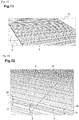
- the layer of insulating material consisting of insulating plates 2 glued to the hollow brick shell 1 forms an upper surface which is also flat and continuous and, figure 11 , we begin to install on this surface corrugated sheets 3 of the first type, bituminized with cellulose fibers, starting at the bottom of the slope.
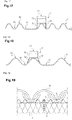
- These corrugated plates 3 have a repeating pattern consisting of a series of three corrugations separated from another series of three corrugations by an extended recess 31 which is flat.
- Each corrugation has a top 30 bordered by two hollows 31 and these hollows 31 within a series of three corrugations are narrow and rounded compared to the extended and flat hollow 31 separating the series.
- the side edges of the corrugated plates overlap / overlap within a strip of corrugated plates just as for the superposition / the overlapping of the end edges along the slope between corrugated plates of two successive strips along the slope, the end of the higher corrugated plate along the slope overlapping that of the lower of the two strips. This is what we see figure 12 for the ends of corrugated sheets along the slope between two strips.
- the corrugations are elongated / arranged in the direction of the slope in order to allow the flow of any water which may have been found on the corrugated plates.
- anchoring screws 6 arranged along the superposition of the end edges of corrugated plates 3 and making it possible to fix two corrugated plates each time to the insulation plates 2. These anchoring screws 6 are screwed through the corrugated plates 3 at the level of the tops 30 of the corrugations. Note that for all types of corrugated sheets, the anchoring screws are preferably installed on the tops of the corrugations in order to guarantee optimum sealing against liquid water.
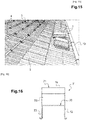
- slats 4 are then installed in parallel lines perpendicular to the slope and the spacing of which is adapted to the dimensions of the roofing elements which are here tiles 5 which will cover the whole.
- the slats 4 are therefore also perpendicular to the corrugations.
- the slats 4 are fixed to the insulating plates 2 and to the corrugated plates 3 by anchoring screws 6 by means of connecting pieces 7.
- the anchor screw is installed lower in the direction of the slope with respect to the slat.
- the anchor screw is installed higher up in the direction of the slope with respect to the slat and a connecting piece is used which makes it possible to retain the slat by its lateral face on the opposite side to the screw in order to prevent the slat from escaping and sliding down the slope.
- the tiles 5 which will be laid have lugs on their underside and the slats 4 make it possible to retain the tiles 5 along the slope by their lugs.
- a line of slats is implemented along the bottom of the slope in order to simply raise the tiles of the bottom row relative to the corrugated plates and to allow better ventilation between the corrugated plates and the tiles and prevent the bottom tile from applying directly to the corrugated plate at the bottom of the slope.
- the connecting piece 7 encloses by its claw 73, 71, 74 partly the slat 4 passing through the top of the latter.
- the connecting piece 7 is placed on a corrugation top 30 so that the anchor screw 6 is screwed through the corrugation top 30 and into the layer of insulating material 2 which is below the corrugated plates 3.
- the anchoring screws 6 serving to fix the slats 4 by means of the connecting pieces therefore also serve to complete the fixing of the corrugated plates 3 to the insulating material. From this arrangement, it also follows that the slats 4, by means of the connecting pieces 7, are also found fixed to the corrugated plates 3.
- the anchoring piece 7 'with legs and even 7 without legs is relatively stable once placed on the slat and the top of the corrugation.
- the anchor screw for the connecting piece will here be screwed through a superposition of two side edges of two corrugated plates in a row. At other locations along the slat 4, it may be a single corrugated plate which is crossed by the screwing of the anchor screw 6.
- anchor screws 6 are all screwed at the level of the tops of the corrugations of the corrugated plates and it is therefore possible to use anchor screws of the same length without the need for anchor screws of different lengths. If some anchor screws had been installed in corrugation hollows, then anchor screws 6, 8 of different lengths of shaft 61, 81 could have been provided for fixing in a hollow or flat (short anchor screw) and for fixing at the top (long anchor screw).
- An electric screwdriver 11 is used with a TORX® screwdriver bit because the head 60, 80 of the anchor screw 6, 8 has a drive recess 64, 84 for TORX® screwing (or even unscrewing).
- anchoring screws In practice, it is preferable to install the anchoring screws at the level of the tops of the corrugations and if anchoring screws of different shank lengths and / or different thread pitches and / or different and therefore different thread diameters are provided. types of anchoring screws, this is essentially a function of the height of the corrugations and / or the thickness and nature of the insulating material which are used. Anchor screws can therefore be chosen essentially according to the characteristics of the corrugated plates, the location of the screw (hollow / flat or top) and the insulating material.
- an anchoring screw is used, the length of which is adapted to the height of the corrugations and to the thickness of the insulating material so that the anchoring screw enters the insulating material well but does not pass through it completely and does not not stick out on the other side of the insulating material.
- the measuring meter is intended to correctly position the slat 4 with respect to a previous slat along the slope or with respect to the lower edge of the slope, depending on the dimensions of the tiles.
- the lower tiles must have their lower edges above the gutter 10 arranged at the edge of the roof.
- the slats 4 being fixed, we can install the tiles 5 on the slats starting with the bottom row as visible figure 15 .
- anchor screws are used initially, before the installation of the slats, to secure the corrugated sheets to the insulating material, and other anchor screws are used in a second step to secure the slats. , in particular by means of connecting pieces, to the corrugated plates and, preferably, also to the insulating material.
- This first use of the anchoring screws can be carried out to ensure an optimal fixing of the corrugated sheets or only to ensure a minimum fixing, less than the optimal fixing, during the realization of the cover, the second use of the anchoring screws allowing to '' achieve optimum fixation of corrugated sheets.
- the optimum fixing corresponds to a degree of fixing which allows the roof to resist tearing or destruction, in particular due to the wind, more particularly with regard to corrugated sheets.
- the fixing of the corrugated sheets should preferably be optimal.
- the weight and type of the roofing elements can also influence the degree of attachment since these elements apply a certain weight to the slats and corrugated sheets.
- figure 19 where a corrugated plate of the first type 3 is fixed on the insulation 2 by a short anchoring screw 6 in this example in which there is no connection piece or slat implemented.
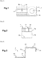
- the figures 1 to 4 show a simple connecting piece 7 (without side legs) intended to be installed to press the slat 4 against the corrugated plate 3, 3 ', 3 "and allowing the slat 4 to be fixed to the corrugated plate 3, 3', 3" and to the insulating material 2.
- the connecting piece 7 is formed of several parts: a plate 70 and a retaining claw 71, 73, 74 of the slat. We will see in relation to the figures 16 to 18 that it is also possible to implement connecting pieces 7 'further comprising two side tabs 72.
- the connecting piece 7, 7' is metallic.
- the plate 70 which is flat and here square in shape is intended to be placed flat on a top 30 of corrugation of the corrugated plate 3, 3 ', 3 ", the connecting piece 7, 7' being installed on a top.
- a through hole 78 is made in the center of the plate 70 in order to allow the passage of an anchor screw shank 6, 8 without the screw thread having to force or widen the screw. through hole 78 when screwing in the anchor screw but, preferably, preventing extraction of the screw through through hole 78 by simple axial pulling.
- through hole 78 has a diameter equal to approximately 3/4 of the width of the thread 62, 82 of the anchor screw, this to allow a better mesh between the anchor screw and the plate 70.
- a greater coupling between the anchor screw and the plate 70 is thus implemented to take account of the mechanical properties of the insulation.
- the retaining claw 73, 71, 74 of the slat is continuous on one side of the plate 70 which is in relation with the top 30 of the corrugation.
- the retaining claw 73, 71, 74 which is in several portions at least partially encloses the slat 4 and, in this example, encloses its upper face by a portion 71, one of the two lateral faces over its entire height by a portion 73 and the other side face over part of its height by a portion 74.
- the slat is directly applied against the top of the corrugations by the retaining claw 73, 71, 74 of the connecting piece 7.
- slats 4 made of plastic, preferably perforated metal, of wood and having different dimensions, the connecting piece 7, 7 'used being adapted to the slat.
- metal slats 4 the metals of the slats 4 and of the connecting pieces 7, 7 'are chosen for their compatibility and, in particular, to avoid oxidation-reduction reactions between them.
- the side legs 72 are either vertical ( figures 16 and 17 ) or inclined downwards and outwards ( figure 18 ), the lower ends of the side legs 72 being rounded and being intended to come to rest against the upper face of the corrugated plate 3, 3 ', 3 ", on either side of a top, the connecting piece being astride the top 30 of the corrugation.
- the inclination of the side legs relative to the plate 70 is adapted to the shape and dimensions of the corrugations: on the figures 16 and 17 , the side legs 72 of the connecting piece 7 'are vertical and perpendicular to the plate 70, figure 18 the side tabs 72 of the connecting piece 7 'gradually move away from one another going downward.
- the inclination of the side legs 72 can be adjusted by forcing or twisting the metal of the connecting piece 7 '.
- ribs 77 obtained in particular by stamping. These ribs can also be produced on the connecting pieces 7 'with lateral tabs 72.
- the connecting piece 7, 7 ' is made of metal, for example stainless steel, galvanized steel, and is obtained by cutting a blank from a metal plate and this blank is then folded to form the different parts: plate 70 , claw 73, 71, 74 for retaining the slat and possible tabs 72.
- the metal thickness is between 1 mm and 1.5 mm and is preferably 1.2 mm.
- a hole 79 has been provided in this example through the portion 71 of the claw of the connecting piece 7 on the figure 1 to 4 .
- the hole 79 is omitted.
- the hole 79 can also be made on the connecting pieces 7 'with lateral tabs 72.
- a V-shaped notch part of the portion 71 of the claw and we bend it downwards and it serves as nailing point of the claw to the batten the installer places the claw on the batten and gives a mallet on the claw so that the point of the V goes into the latte.
- Corrugated plates differ in particular by the presence or absence of plates and the number of corrugations / waves between two plates.
- the corrugated plate 3 of the first type of the figure 6 or the figure 17 comprises series of three corrugations and a flat hollow, each corrugation being of a width allowing the use of a connecting piece 7 'with vertical lugs 72 in case they are implemented.
- the corrugated plate 3 'of the second type of the figure 5 or the figure 18 comprises series of two corrugations separated by a flat hollow.
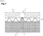
- the 3 "corrugated plate of the third type of the figure 7 has regular waves and does not have a flat.
- Anchor screws of different lengths are shown figures 8 and 9 .
- the anchor screws 6, 8 have heads 60, 80 at an upper end and spikes 63, 83 at a lower end.
- the points 63, 83 of the lower ends of the anchor screws are pointed and of the self-piercing type in the manner of a nail.
- a helical thread 62, 82 is arranged along the shank 61, 81.
- Two lengths of anchoring screws can be used for a given embodiment if the corrugated plates are fixed to the insulating material by screwing short anchoring screws at the level of the hollows, possibly of the flats, of the corrugations and by screwing in the screws. '' long anchoring at the peaks of undulations for fixing the slats and / or simply fixing the corrugated plates to the insulating material.
- anchor screws of the same length for the fixings in the hollows / flats and for the fixings at the tops of the corrugations. If all the anchor screw fastenings are carried out, as preferentially, on the tops of the corrugations, the length of the anchoring screw with long or short shank is chosen according to the height of the corrugations and the thickness of the insulating material, all the anchoring screws then being of the same length.
- anchoring screws of different lengths can be provided.
- two lengths of anchor screws are provided with short anchor screws and long anchor screws.
- the length of the anchor screw is chosen according to the dimensional characteristics of the corrugated sheets, the location where the anchor screw is installed (on a top or in a hollow or flat) and the thickness of the insulating panels.
- the anchoring screws of the slats also enter the insulating material as this provides additional fixing of the corrugated plate to the insulating material.
- the lengths (or heights depending on the point of view) of the two anchor screws 6, 8 are however different, the shorter 6 measures 95 mm in length / height with 5 turns for the net and the longest 8 measures 125 mm in length / height with 7 turns for the net.
- a screw of 95 mm length / height can be used and with an insulating panel of thickness greater than 120 mm, a screw of 125 mm length / height can be used.
- Anchor screws are produced by industrial hot printing or molding, and they can be made of nylon or polypropylene polymer or their derivatives.
- a connecting piece 7, 7 ' is used to fix the slats to the corrugated plates and to the insulating material, the anchoring screws being arranged laterally to the slats.
- the anchoring screws can pass through the slats and / or if the anchoring screw is disposed lateral to the slat, the head 60, 80 of the screw anchor which is relatively wide can be applied by a part of its lower face on the upper face of the slat to press it against the top of the corrugated plate.
- a large diameter washer can be provided on the underside of the anchor screw which is applied against the upper face of the slat. This washer can be replaced by a flat drilled plate resting on the upper face of the batten.
- the and the retaining claw of the connecting piece can then be adapted to be a simple finger in the same plane as the plate 70, the finger resting on the upper face of the slat 4 which is in the recess, the latter 4 being then enclosed, downwards and upstream, downstream sides (in the direction of the slope, the upstream being towards the high side of the slope), by the recess and, upwards, by the finger constituting the claw of the connecting piece.
Landscapes
- Engineering & Computer Science (AREA)
- Architecture (AREA)
- Civil Engineering (AREA)
- Structural Engineering (AREA)
- Mechanical Engineering (AREA)
- Roof Covering Using Slabs Or Stiff Sheets (AREA)
- Organic Low-Molecular-Weight Compounds And Preparation Thereof (AREA)
- Conveying And Assembling Of Building Elements In Situ (AREA)
Applications Claiming Priority (1)
| Application Number | Priority Date | Filing Date | Title |
|---|---|---|---|
| FR2000442A FR3106351B1 (fr) | 2020-01-17 | 2020-01-17 | Procédé de réalisation d’une couverture de toiture d’un bâtiment et ensemble d’éléments adaptés. |
Publications (3)
| Publication Number | Publication Date |
|---|---|
| EP3851608A2 true EP3851608A2 (de) | 2021-07-21 |
| EP3851608A3 EP3851608A3 (de) | 2021-09-22 |
| EP3851608B1 EP3851608B1 (de) | 2022-10-05 |
Family
ID=70228219
Family Applications (1)
| Application Number | Title | Priority Date | Filing Date |
|---|---|---|---|
| EP21151187.8A Active EP3851608B1 (de) | 2020-01-17 | 2021-01-12 | Verfahren zur erstelllung einer dachabdeckung eines gebäudes |
Country Status (3)
| Country | Link |
|---|---|
| EP (1) | EP3851608B1 (de) |
| ES (1) | ES2931048T3 (de) |
| FR (1) | FR3106351B1 (de) |
Cited By (1)
| Publication number | Priority date | Publication date | Assignee | Title |
|---|---|---|---|---|
| CN114687756A (zh) * | 2022-03-15 | 2022-07-01 | 中国铁道科学研究院集团有限公司铁道建筑研究所 | 一种铁路隧道用玄武岩波纹板及其制备方法 |
Citations (13)
| Publication number | Priority date | Publication date | Assignee | Title |
|---|---|---|---|---|
| FR2496551A1 (fr) | 1980-12-19 | 1982-06-25 | Omnium Fs Indl Cal | Machine a profiler des materiaux souples avec ou sans alternances predeterminees d'ondes et de zones plates, et materiaux ainsi obtenus |
| GB2092202A (en) | 1981-01-29 | 1982-08-11 | Itw Ltd | Overroofing of buildings |
| GB2169051A (en) | 1984-12-21 | 1986-07-02 | Sfs Stadler Ag | Screws for fastening roof or wall liners |
| DE3515419C1 (de) | 1985-04-29 | 1986-08-14 | Walter Dipl.-Ing. 4630 Bochum Holzapfel | Abstandhalter zur Distanzierung einer unter einer Dachabdeckung vorhandenen Dachunterkonstruktion von der tragenden Dachkonstruktion |
| US4763456A (en) | 1987-08-03 | 1988-08-16 | Giannuzzi Louis | Roof anchor and stress plate assembly |
| US4892429A (en) | 1987-08-03 | 1990-01-09 | Giannuzzi Louis | Roof anchor and stress plate assembly |
| FR2637633A1 (fr) | 1988-10-12 | 1990-04-13 | Omnium Francais Indl Cal | Toit en tuiles plates, son procede de realisation, et element de support et repartition de charge pour un tel toit |
| DE9407875U1 (de) | 1994-05-16 | 1994-07-07 | Windsheimer, Hans, 91583 Schillingsfürst | Befestigungselement |
| US5692352A (en) | 1984-01-04 | 1997-12-02 | Harold Simpson, Inc. | Roof panel standing seam assemblies |
| FR2755712B1 (fr) | 1996-11-12 | 1999-08-06 | Onduline Sa | Materiau de couverture |
| FR2827017A1 (fr) | 2001-07-05 | 2003-01-10 | Ejot Verbindungstech Gmbh & Co | Vis a enfoncer dans un materiau a faible resistance mecanique. |
| EP1645698A1 (de) | 2004-10-05 | 2006-04-12 | Rockwool International A/S | Eine Dachkonstruktion |
| US8677718B2 (en) | 2011-05-02 | 2014-03-25 | Joseph T. Marshall | Retrofit mounting clip for an exterior building surface |
-
2020
- 2020-01-17 FR FR2000442A patent/FR3106351B1/fr active Active
-
2021
- 2021-01-12 ES ES21151187T patent/ES2931048T3/es active Active
- 2021-01-12 EP EP21151187.8A patent/EP3851608B1/de active Active
Patent Citations (13)
| Publication number | Priority date | Publication date | Assignee | Title |
|---|---|---|---|---|
| FR2496551A1 (fr) | 1980-12-19 | 1982-06-25 | Omnium Fs Indl Cal | Machine a profiler des materiaux souples avec ou sans alternances predeterminees d'ondes et de zones plates, et materiaux ainsi obtenus |
| GB2092202A (en) | 1981-01-29 | 1982-08-11 | Itw Ltd | Overroofing of buildings |
| US5692352A (en) | 1984-01-04 | 1997-12-02 | Harold Simpson, Inc. | Roof panel standing seam assemblies |
| GB2169051A (en) | 1984-12-21 | 1986-07-02 | Sfs Stadler Ag | Screws for fastening roof or wall liners |
| DE3515419C1 (de) | 1985-04-29 | 1986-08-14 | Walter Dipl.-Ing. 4630 Bochum Holzapfel | Abstandhalter zur Distanzierung einer unter einer Dachabdeckung vorhandenen Dachunterkonstruktion von der tragenden Dachkonstruktion |
| US4763456A (en) | 1987-08-03 | 1988-08-16 | Giannuzzi Louis | Roof anchor and stress plate assembly |
| US4892429A (en) | 1987-08-03 | 1990-01-09 | Giannuzzi Louis | Roof anchor and stress plate assembly |
| FR2637633A1 (fr) | 1988-10-12 | 1990-04-13 | Omnium Francais Indl Cal | Toit en tuiles plates, son procede de realisation, et element de support et repartition de charge pour un tel toit |
| DE9407875U1 (de) | 1994-05-16 | 1994-07-07 | Windsheimer, Hans, 91583 Schillingsfürst | Befestigungselement |
| FR2755712B1 (fr) | 1996-11-12 | 1999-08-06 | Onduline Sa | Materiau de couverture |
| FR2827017A1 (fr) | 2001-07-05 | 2003-01-10 | Ejot Verbindungstech Gmbh & Co | Vis a enfoncer dans un materiau a faible resistance mecanique. |
| EP1645698A1 (de) | 2004-10-05 | 2006-04-12 | Rockwool International A/S | Eine Dachkonstruktion |
| US8677718B2 (en) | 2011-05-02 | 2014-03-25 | Joseph T. Marshall | Retrofit mounting clip for an exterior building surface |
Cited By (1)
| Publication number | Priority date | Publication date | Assignee | Title |
|---|---|---|---|---|
| CN114687756A (zh) * | 2022-03-15 | 2022-07-01 | 中国铁道科学研究院集团有限公司铁道建筑研究所 | 一种铁路隧道用玄武岩波纹板及其制备方法 |
Also Published As
| Publication number | Publication date |
|---|---|
| ES2931048T3 (es) | 2022-12-23 |
| FR3106351B1 (fr) | 2022-04-01 |
| EP3851608B1 (de) | 2022-10-05 |
| FR3106351A1 (fr) | 2021-07-23 |
| EP3851608A3 (de) | 2021-09-22 |
Similar Documents
| Publication | Publication Date | Title |
|---|---|---|
| FR2466581A1 (fr) | Latte pour toiture | |
| EP3112547B2 (de) | Stützzubehör für die auskleidung einer wand, das klemmbacken für eine membran umfasst | |
| EP1282753B1 (de) | Befestigungsvorrichtung für die längsränder von platten, latten oder wandverkleidungen mit kraftverteilung | |
| EP3851608B1 (de) | Verfahren zur erstelllung einer dachabdeckung eines gebäudes | |
| EP0399874B1 (de) | Lattenvorrichtung, insbesondere für Überdeckung von geneigten Dächern | |
| FR2966228A1 (fr) | Support polyvalent de fixation destine a la pose des modules de recuperation thermique du rayonnement solaire | |
| EP2646628A1 (de) | Element mit einer tragefläche zur aufnahme einer fassadenplatte, insbesondere einer gipsbauplatte | |
| FR2524524A1 (fr) | Procede et dispositif de fixation d'une couverture isolante sur une toiture de batiment et assemblage en resultant | |
| FR3041835A1 (fr) | Mecanisme de fixation de panneaux solaires sur des plaques metalliques formant un toit. | |
| FR2516132A1 (fr) | Closoir universel de faitage de toiture | |
| EP2644798B1 (de) | Bitumenimprägniertes geformtes Firstband aus Zellulose, und Anwendung | |
| EP2489809B1 (de) | Verfahren zur Herstellung eines Strukturelements, und so hergestellte Elemente | |
| FR2680816A1 (fr) | Couverture etanche de batiment et son procede de pose. | |
| FR2541709A1 (fr) | Procedes et bacs autoportants pour la construction de toitures en tuiles rondes, toitures et batiments obtenus | |
| EP2628870A1 (de) | Aufsatzvorrichtung zur Dacherhöhung bei Holzbalken | |
| EP1496169B1 (de) | Herstellungsverfahren für ein Dach mit Hohlziegeln und solch ein Dach | |
| EP1707703A1 (de) | Holzschindel | |
| EP3366858B1 (de) | Flachziegel für eine dacheindeckung eines gebäudes, der eine verstärkte abdichtung umfasst | |
| FR2860817A1 (fr) | Bardeau perfectionne destine a la realisation de couverture bois | |
| EP0213039A2 (de) | Wärmegedämmtes Dach | |
| FR2627212A1 (fr) | Bardure isolante et element d'accrochage pour la realiser | |
| FR2534958A1 (fr) | Element de construction de type bardeau | |
| EP0444371A1 (de) | Stütz- und Lastverteilungselement für mit flachen Ziegeln bedecktes Dach, und dieses Element enthaltendes Dach | |
| EP2712976B1 (de) | Verkleidungsplatte | |
| BE1018203A3 (fr) | Crochet d'ancrage pour toiture. |
Legal Events
| Date | Code | Title | Description |
|---|---|---|---|
| PUAI | Public reference made under article 153(3) epc to a published international application that has entered the european phase |
Free format text: ORIGINAL CODE: 0009012 |
|
| STAA | Information on the status of an ep patent application or granted ep patent |
Free format text: STATUS: THE APPLICATION HAS BEEN PUBLISHED |
|
| AK | Designated contracting states |
Kind code of ref document: A2 Designated state(s): AL AT BE BG CH CY CZ DE DK EE ES FI FR GB GR HR HU IE IS IT LI LT LU LV MC MK MT NL NO PL PT RO RS SE SI SK SM TR |
|
| PUAL | Search report despatched |
Free format text: ORIGINAL CODE: 0009013 |
|
| AK | Designated contracting states |
Kind code of ref document: A3 Designated state(s): AL AT BE BG CH CY CZ DE DK EE ES FI FR GB GR HR HU IE IS IT LI LT LU LV MC MK MT NL NO PL PT RO RS SE SI SK SM TR |
|
| RIC1 | Information provided on ipc code assigned before grant |
Ipc: E04D 13/16 20060101ALI20210816BHEP Ipc: E04D 12/00 20060101ALI20210816BHEP Ipc: E04D 3/36 20060101AFI20210816BHEP |
|
| STAA | Information on the status of an ep patent application or granted ep patent |
Free format text: STATUS: REQUEST FOR EXAMINATION WAS MADE |
|
| 17P | Request for examination filed |
Effective date: 20211013 |
|
| RBV | Designated contracting states (corrected) |
Designated state(s): AL AT BE BG CH CY CZ DE DK EE ES FI FR GB GR HR HU IE IS IT LI LT LU LV MC MK MT NL NO PL PT RO RS SE SI SK SM TR |
|
| RIN1 | Information on inventor provided before grant (corrected) |
Inventor name: TORELLI, DAVIDE Inventor name: STEFANAZZI, ALBERTO Inventor name: LUCCHINI, ANGELO |
|
| GRAP | Despatch of communication of intention to grant a patent |
Free format text: ORIGINAL CODE: EPIDOSNIGR1 |
|
| STAA | Information on the status of an ep patent application or granted ep patent |
Free format text: STATUS: GRANT OF PATENT IS INTENDED |
|
| INTG | Intention to grant announced |
Effective date: 20220518 |
|
| GRAS | Grant fee paid |
Free format text: ORIGINAL CODE: EPIDOSNIGR3 |
|
| GRAA | (expected) grant |
Free format text: ORIGINAL CODE: 0009210 |
|
| STAA | Information on the status of an ep patent application or granted ep patent |
Free format text: STATUS: THE PATENT HAS BEEN GRANTED |
|
| AK | Designated contracting states |
Kind code of ref document: B1 Designated state(s): AL AT BE BG CH CY CZ DE DK EE ES FI FR GB GR HR HU IE IS IT LI LT LU LV MC MK MT NL NO PL PT RO RS SE SI SK SM TR |
|
| REG | Reference to a national code |
Ref country code: GB Ref legal event code: FG4D Free format text: NOT ENGLISH |
|
| REG | Reference to a national code |
Ref country code: CH Ref legal event code: EP |
|
| REG | Reference to a national code |
Ref country code: AT Ref legal event code: REF Ref document number: 1522848 Country of ref document: AT Kind code of ref document: T Effective date: 20221015 |
|
| REG | Reference to a national code |
Ref country code: IE Ref legal event code: FG4D Free format text: LANGUAGE OF EP DOCUMENT: FRENCH |
|
| REG | Reference to a national code |
Ref country code: DE Ref legal event code: R096 Ref document number: 602021000487 Country of ref document: DE |
|
| REG | Reference to a national code |
Ref country code: ES Ref legal event code: FG2A Ref document number: 2931048 Country of ref document: ES Kind code of ref document: T3 Effective date: 20221223 |
|
| REG | Reference to a national code |
Ref country code: LT Ref legal event code: MG9D |
|
| REG | Reference to a national code |
Ref country code: NL Ref legal event code: MP Effective date: 20221005 |
|
| REG | Reference to a national code |
Ref country code: AT Ref legal event code: MK05 Ref document number: 1522848 Country of ref document: AT Kind code of ref document: T Effective date: 20221005 |
|
| PG25 | Lapsed in a contracting state [announced via postgrant information from national office to epo] |
Ref country code: NL Free format text: LAPSE BECAUSE OF FAILURE TO SUBMIT A TRANSLATION OF THE DESCRIPTION OR TO PAY THE FEE WITHIN THE PRESCRIBED TIME-LIMIT Effective date: 20221005 |
|
| PG25 | Lapsed in a contracting state [announced via postgrant information from national office to epo] |
Ref country code: SE Free format text: LAPSE BECAUSE OF FAILURE TO SUBMIT A TRANSLATION OF THE DESCRIPTION OR TO PAY THE FEE WITHIN THE PRESCRIBED TIME-LIMIT Effective date: 20221005 Ref country code: PT Free format text: LAPSE BECAUSE OF FAILURE TO SUBMIT A TRANSLATION OF THE DESCRIPTION OR TO PAY THE FEE WITHIN THE PRESCRIBED TIME-LIMIT Effective date: 20230206 Ref country code: NO Free format text: LAPSE BECAUSE OF FAILURE TO SUBMIT A TRANSLATION OF THE DESCRIPTION OR TO PAY THE FEE WITHIN THE PRESCRIBED TIME-LIMIT Effective date: 20230105 Ref country code: LT Free format text: LAPSE BECAUSE OF FAILURE TO SUBMIT A TRANSLATION OF THE DESCRIPTION OR TO PAY THE FEE WITHIN THE PRESCRIBED TIME-LIMIT Effective date: 20221005 Ref country code: FI Free format text: LAPSE BECAUSE OF FAILURE TO SUBMIT A TRANSLATION OF THE DESCRIPTION OR TO PAY THE FEE WITHIN THE PRESCRIBED TIME-LIMIT Effective date: 20221005 Ref country code: AT Free format text: LAPSE BECAUSE OF FAILURE TO SUBMIT A TRANSLATION OF THE DESCRIPTION OR TO PAY THE FEE WITHIN THE PRESCRIBED TIME-LIMIT Effective date: 20221005 |
|
| PG25 | Lapsed in a contracting state [announced via postgrant information from national office to epo] |
Ref country code: RS Free format text: LAPSE BECAUSE OF FAILURE TO SUBMIT A TRANSLATION OF THE DESCRIPTION OR TO PAY THE FEE WITHIN THE PRESCRIBED TIME-LIMIT Effective date: 20221005 Ref country code: PL Free format text: LAPSE BECAUSE OF FAILURE TO SUBMIT A TRANSLATION OF THE DESCRIPTION OR TO PAY THE FEE WITHIN THE PRESCRIBED TIME-LIMIT Effective date: 20221005 Ref country code: LV Free format text: LAPSE BECAUSE OF FAILURE TO SUBMIT A TRANSLATION OF THE DESCRIPTION OR TO PAY THE FEE WITHIN THE PRESCRIBED TIME-LIMIT Effective date: 20221005 Ref country code: IS Free format text: LAPSE BECAUSE OF FAILURE TO SUBMIT A TRANSLATION OF THE DESCRIPTION OR TO PAY THE FEE WITHIN THE PRESCRIBED TIME-LIMIT Effective date: 20230205 Ref country code: HR Free format text: LAPSE BECAUSE OF FAILURE TO SUBMIT A TRANSLATION OF THE DESCRIPTION OR TO PAY THE FEE WITHIN THE PRESCRIBED TIME-LIMIT Effective date: 20221005 Ref country code: GR Free format text: LAPSE BECAUSE OF FAILURE TO SUBMIT A TRANSLATION OF THE DESCRIPTION OR TO PAY THE FEE WITHIN THE PRESCRIBED TIME-LIMIT Effective date: 20230106 |
|
| P01 | Opt-out of the competence of the unified patent court (upc) registered |
Effective date: 20230524 |
|
| REG | Reference to a national code |
Ref country code: DE Ref legal event code: R097 Ref document number: 602021000487 Country of ref document: DE |
|
| PG25 | Lapsed in a contracting state [announced via postgrant information from national office to epo] |
Ref country code: SM Free format text: LAPSE BECAUSE OF FAILURE TO SUBMIT A TRANSLATION OF THE DESCRIPTION OR TO PAY THE FEE WITHIN THE PRESCRIBED TIME-LIMIT Effective date: 20221005 Ref country code: RO Free format text: LAPSE BECAUSE OF FAILURE TO SUBMIT A TRANSLATION OF THE DESCRIPTION OR TO PAY THE FEE WITHIN THE PRESCRIBED TIME-LIMIT Effective date: 20221005 Ref country code: EE Free format text: LAPSE BECAUSE OF FAILURE TO SUBMIT A TRANSLATION OF THE DESCRIPTION OR TO PAY THE FEE WITHIN THE PRESCRIBED TIME-LIMIT Effective date: 20221005 Ref country code: DK Free format text: LAPSE BECAUSE OF FAILURE TO SUBMIT A TRANSLATION OF THE DESCRIPTION OR TO PAY THE FEE WITHIN THE PRESCRIBED TIME-LIMIT Effective date: 20221005 Ref country code: CZ Free format text: LAPSE BECAUSE OF FAILURE TO SUBMIT A TRANSLATION OF THE DESCRIPTION OR TO PAY THE FEE WITHIN THE PRESCRIBED TIME-LIMIT Effective date: 20221005 |
|
| REG | Reference to a national code |
Ref country code: DE Ref legal event code: R119 Ref document number: 602021000487 Country of ref document: DE |
|
| PLBE | No opposition filed within time limit |
Free format text: ORIGINAL CODE: 0009261 |
|
| STAA | Information on the status of an ep patent application or granted ep patent |
Free format text: STATUS: NO OPPOSITION FILED WITHIN TIME LIMIT |
|
| PG25 | Lapsed in a contracting state [announced via postgrant information from national office to epo] |
Ref country code: SK Free format text: LAPSE BECAUSE OF FAILURE TO SUBMIT A TRANSLATION OF THE DESCRIPTION OR TO PAY THE FEE WITHIN THE PRESCRIBED TIME-LIMIT Effective date: 20221005 Ref country code: AL Free format text: LAPSE BECAUSE OF FAILURE TO SUBMIT A TRANSLATION OF THE DESCRIPTION OR TO PAY THE FEE WITHIN THE PRESCRIBED TIME-LIMIT Effective date: 20221005 |
|
| 26N | No opposition filed |
Effective date: 20230706 |
|
| PG25 | Lapsed in a contracting state [announced via postgrant information from national office to epo] |
Ref country code: LU Free format text: LAPSE BECAUSE OF NON-PAYMENT OF DUE FEES Effective date: 20230112 |
|
| REG | Reference to a national code |
Ref country code: BE Ref legal event code: MM Effective date: 20230131 |
|
| PG25 | Lapsed in a contracting state [announced via postgrant information from national office to epo] |
Ref country code: DE Free format text: LAPSE BECAUSE OF NON-PAYMENT OF DUE FEES Effective date: 20230801 |
|
| PG25 | Lapsed in a contracting state [announced via postgrant information from national office to epo] |
Ref country code: SI Free format text: LAPSE BECAUSE OF FAILURE TO SUBMIT A TRANSLATION OF THE DESCRIPTION OR TO PAY THE FEE WITHIN THE PRESCRIBED TIME-LIMIT Effective date: 20221005 Ref country code: BE Free format text: LAPSE BECAUSE OF NON-PAYMENT OF DUE FEES Effective date: 20230131 |
|
| PG25 | Lapsed in a contracting state [announced via postgrant information from national office to epo] |
Ref country code: IE Free format text: LAPSE BECAUSE OF NON-PAYMENT OF DUE FEES Effective date: 20230112 |
|
| PG25 | Lapsed in a contracting state [announced via postgrant information from national office to epo] |
Ref country code: MC Free format text: LAPSE BECAUSE OF FAILURE TO SUBMIT A TRANSLATION OF THE DESCRIPTION OR TO PAY THE FEE WITHIN THE PRESCRIBED TIME-LIMIT Effective date: 20221005 |
|
| PG25 | Lapsed in a contracting state [announced via postgrant information from national office to epo] |
Ref country code: MC Free format text: LAPSE BECAUSE OF FAILURE TO SUBMIT A TRANSLATION OF THE DESCRIPTION OR TO PAY THE FEE WITHIN THE PRESCRIBED TIME-LIMIT Effective date: 20221005 |
|
| REG | Reference to a national code |
Ref country code: CH Ref legal event code: PL |
|
| PG25 | Lapsed in a contracting state [announced via postgrant information from national office to epo] |
Ref country code: CH Free format text: LAPSE BECAUSE OF NON-PAYMENT OF DUE FEES Effective date: 20240131 |
|
| PG25 | Lapsed in a contracting state [announced via postgrant information from national office to epo] |
Ref country code: CH Free format text: LAPSE BECAUSE OF NON-PAYMENT OF DUE FEES Effective date: 20240131 |
|
| PG25 | Lapsed in a contracting state [announced via postgrant information from national office to epo] |
Ref country code: BG Free format text: LAPSE BECAUSE OF FAILURE TO SUBMIT A TRANSLATION OF THE DESCRIPTION OR TO PAY THE FEE WITHIN THE PRESCRIBED TIME-LIMIT Effective date: 20221005 |
|
| PG25 | Lapsed in a contracting state [announced via postgrant information from national office to epo] |
Ref country code: BG Free format text: LAPSE BECAUSE OF FAILURE TO SUBMIT A TRANSLATION OF THE DESCRIPTION OR TO PAY THE FEE WITHIN THE PRESCRIBED TIME-LIMIT Effective date: 20221005 |
|
| PG25 | Lapsed in a contracting state [announced via postgrant information from national office to epo] |
Ref country code: CY Free format text: LAPSE BECAUSE OF FAILURE TO SUBMIT A TRANSLATION OF THE DESCRIPTION OR TO PAY THE FEE WITHIN THE PRESCRIBED TIME-LIMIT; INVALID AB INITIO Effective date: 20210112 |
|
| PG25 | Lapsed in a contracting state [announced via postgrant information from national office to epo] |
Ref country code: HU Free format text: LAPSE BECAUSE OF FAILURE TO SUBMIT A TRANSLATION OF THE DESCRIPTION OR TO PAY THE FEE WITHIN THE PRESCRIBED TIME-LIMIT; INVALID AB INITIO Effective date: 20210112 |
|
| GBPC | Gb: european patent ceased through non-payment of renewal fee |
Effective date: 20250112 |
|
| PG25 | Lapsed in a contracting state [announced via postgrant information from national office to epo] |
Ref country code: GB Free format text: LAPSE BECAUSE OF NON-PAYMENT OF DUE FEES Effective date: 20250112 |
|
| PG25 | Lapsed in a contracting state [announced via postgrant information from national office to epo] |
Ref country code: TR Free format text: LAPSE BECAUSE OF FAILURE TO SUBMIT A TRANSLATION OF THE DESCRIPTION OR TO PAY THE FEE WITHIN THE PRESCRIBED TIME-LIMIT Effective date: 20221005 |
|
| PGFP | Annual fee paid to national office [announced via postgrant information from national office to epo] |
Ref country code: FR Payment date: 20251202 Year of fee payment: 6 |
|
| PGFP | Annual fee paid to national office [announced via postgrant information from national office to epo] |
Ref country code: ES Payment date: 20260210 Year of fee payment: 6 |
|
| PGFP | Annual fee paid to national office [announced via postgrant information from national office to epo] |
Ref country code: IT Payment date: 20260123 Year of fee payment: 6 |