EP3851733B1 - Flüssigkeitsbehälter, der eine elektronische messanzeige mit verbessertem digitalen display umfasst - Google Patents
Flüssigkeitsbehälter, der eine elektronische messanzeige mit verbessertem digitalen display umfasst Download PDFInfo
- Publication number
- EP3851733B1 EP3851733B1 EP20202685.2A EP20202685A EP3851733B1 EP 3851733 B1 EP3851733 B1 EP 3851733B1 EP 20202685 A EP20202685 A EP 20202685A EP 3851733 B1 EP3851733 B1 EP 3851733B1
- Authority
- EP
- European Patent Office
- Prior art keywords
- gas
- region
- digital display
- display
- une
- Prior art date
- Legal status (The legal status is an assumption and is not a legal conclusion. Google has not performed a legal analysis and makes no representation as to the accuracy of the status listed.)
- Active
Links
Images


Classifications
-
- F—MECHANICAL ENGINEERING; LIGHTING; HEATING; WEAPONS; BLASTING
- F17—STORING OR DISTRIBUTING GASES OR LIQUIDS
- F17C—VESSELS FOR CONTAINING OR STORING COMPRESSED, LIQUEFIED OR SOLIDIFIED GASES; FIXED-CAPACITY GAS-HOLDERS; FILLING VESSELS WITH, OR DISCHARGING FROM VESSELS, COMPRESSED, LIQUEFIED, OR SOLIDIFIED GASES
- F17C13/00—Details of vessels or of the filling or discharging of vessels
- F17C13/08—Mounting arrangements for vessels
-
- F—MECHANICAL ENGINEERING; LIGHTING; HEATING; WEAPONS; BLASTING
- F17—STORING OR DISTRIBUTING GASES OR LIQUIDS
- F17C—VESSELS FOR CONTAINING OR STORING COMPRESSED, LIQUEFIED OR SOLIDIFIED GASES; FIXED-CAPACITY GAS-HOLDERS; FILLING VESSELS WITH, OR DISCHARGING FROM VESSELS, COMPRESSED, LIQUEFIED, OR SOLIDIFIED GASES
- F17C2201/00—Vessel construction, in particular geometry, arrangement or size
- F17C2201/01—Shape
- F17C2201/0104—Shape cylindrical
- F17C2201/0109—Shape cylindrical with exteriorly curved end-piece
-
- F—MECHANICAL ENGINEERING; LIGHTING; HEATING; WEAPONS; BLASTING
- F17—STORING OR DISTRIBUTING GASES OR LIQUIDS
- F17C—VESSELS FOR CONTAINING OR STORING COMPRESSED, LIQUEFIED OR SOLIDIFIED GASES; FIXED-CAPACITY GAS-HOLDERS; FILLING VESSELS WITH, OR DISCHARGING FROM VESSELS, COMPRESSED, LIQUEFIED, OR SOLIDIFIED GASES
- F17C2201/00—Vessel construction, in particular geometry, arrangement or size
- F17C2201/03—Orientation
- F17C2201/032—Orientation with substantially vertical main axis
-
- F—MECHANICAL ENGINEERING; LIGHTING; HEATING; WEAPONS; BLASTING
- F17—STORING OR DISTRIBUTING GASES OR LIQUIDS
- F17C—VESSELS FOR CONTAINING OR STORING COMPRESSED, LIQUEFIED OR SOLIDIFIED GASES; FIXED-CAPACITY GAS-HOLDERS; FILLING VESSELS WITH, OR DISCHARGING FROM VESSELS, COMPRESSED, LIQUEFIED, OR SOLIDIFIED GASES
- F17C2201/00—Vessel construction, in particular geometry, arrangement or size
- F17C2201/05—Size
- F17C2201/056—Small (<1 m3)
-
- F—MECHANICAL ENGINEERING; LIGHTING; HEATING; WEAPONS; BLASTING
- F17—STORING OR DISTRIBUTING GASES OR LIQUIDS
- F17C—VESSELS FOR CONTAINING OR STORING COMPRESSED, LIQUEFIED OR SOLIDIFIED GASES; FIXED-CAPACITY GAS-HOLDERS; FILLING VESSELS WITH, OR DISCHARGING FROM VESSELS, COMPRESSED, LIQUEFIED, OR SOLIDIFIED GASES
- F17C2201/00—Vessel construction, in particular geometry, arrangement or size
- F17C2201/05—Size
- F17C2201/058—Size portable (<30 l)
-
- F—MECHANICAL ENGINEERING; LIGHTING; HEATING; WEAPONS; BLASTING
- F17—STORING OR DISTRIBUTING GASES OR LIQUIDS
- F17C—VESSELS FOR CONTAINING OR STORING COMPRESSED, LIQUEFIED OR SOLIDIFIED GASES; FIXED-CAPACITY GAS-HOLDERS; FILLING VESSELS WITH, OR DISCHARGING FROM VESSELS, COMPRESSED, LIQUEFIED, OR SOLIDIFIED GASES
- F17C2205/00—Vessel construction, in particular mounting arrangements, attachments or identifications means
- F17C2205/01—Mounting arrangements
- F17C2205/0123—Mounting arrangements characterised by number of vessels
- F17C2205/0126—One vessel
-
- F—MECHANICAL ENGINEERING; LIGHTING; HEATING; WEAPONS; BLASTING
- F17—STORING OR DISTRIBUTING GASES OR LIQUIDS
- F17C—VESSELS FOR CONTAINING OR STORING COMPRESSED, LIQUEFIED OR SOLIDIFIED GASES; FIXED-CAPACITY GAS-HOLDERS; FILLING VESSELS WITH, OR DISCHARGING FROM VESSELS, COMPRESSED, LIQUEFIED, OR SOLIDIFIED GASES
- F17C2205/00—Vessel construction, in particular mounting arrangements, attachments or identifications means
- F17C2205/01—Mounting arrangements
- F17C2205/0153—Details of mounting arrangements
- F17C2205/0157—Details of mounting arrangements for transport
- F17C2205/0165—Details of mounting arrangements for transport with handgrip
-
- F—MECHANICAL ENGINEERING; LIGHTING; HEATING; WEAPONS; BLASTING
- F17—STORING OR DISTRIBUTING GASES OR LIQUIDS
- F17C—VESSELS FOR CONTAINING OR STORING COMPRESSED, LIQUEFIED OR SOLIDIFIED GASES; FIXED-CAPACITY GAS-HOLDERS; FILLING VESSELS WITH, OR DISCHARGING FROM VESSELS, COMPRESSED, LIQUEFIED, OR SOLIDIFIED GASES
- F17C2205/00—Vessel construction, in particular mounting arrangements, attachments or identifications means
- F17C2205/01—Mounting arrangements
- F17C2205/0153—Details of mounting arrangements
- F17C2205/0188—Hanging up devices
-
- F—MECHANICAL ENGINEERING; LIGHTING; HEATING; WEAPONS; BLASTING
- F17—STORING OR DISTRIBUTING GASES OR LIQUIDS
- F17C—VESSELS FOR CONTAINING OR STORING COMPRESSED, LIQUEFIED OR SOLIDIFIED GASES; FIXED-CAPACITY GAS-HOLDERS; FILLING VESSELS WITH, OR DISCHARGING FROM VESSELS, COMPRESSED, LIQUEFIED, OR SOLIDIFIED GASES
- F17C2205/00—Vessel construction, in particular mounting arrangements, attachments or identifications means
- F17C2205/03—Fluid connections, filters, valves, closure means or other attachments
- F17C2205/0302—Fittings, valves, filters, or components in connection with the gas storage device
- F17C2205/0308—Protective caps
-
- F—MECHANICAL ENGINEERING; LIGHTING; HEATING; WEAPONS; BLASTING
- F17—STORING OR DISTRIBUTING GASES OR LIQUIDS
- F17C—VESSELS FOR CONTAINING OR STORING COMPRESSED, LIQUEFIED OR SOLIDIFIED GASES; FIXED-CAPACITY GAS-HOLDERS; FILLING VESSELS WITH, OR DISCHARGING FROM VESSELS, COMPRESSED, LIQUEFIED, OR SOLIDIFIED GASES
- F17C2205/00—Vessel construction, in particular mounting arrangements, attachments or identifications means
- F17C2205/03—Fluid connections, filters, valves, closure means or other attachments
- F17C2205/0302—Fittings, valves, filters, or components in connection with the gas storage device
- F17C2205/0323—Valves
- F17C2205/0329—Valves manually actuated
-
- F—MECHANICAL ENGINEERING; LIGHTING; HEATING; WEAPONS; BLASTING
- F17—STORING OR DISTRIBUTING GASES OR LIQUIDS
- F17C—VESSELS FOR CONTAINING OR STORING COMPRESSED, LIQUEFIED OR SOLIDIFIED GASES; FIXED-CAPACITY GAS-HOLDERS; FILLING VESSELS WITH, OR DISCHARGING FROM VESSELS, COMPRESSED, LIQUEFIED, OR SOLIDIFIED GASES
- F17C2205/00—Vessel construction, in particular mounting arrangements, attachments or identifications means
- F17C2205/03—Fluid connections, filters, valves, closure means or other attachments
- F17C2205/0302—Fittings, valves, filters, or components in connection with the gas storage device
- F17C2205/0338—Pressure regulators
-
- F—MECHANICAL ENGINEERING; LIGHTING; HEATING; WEAPONS; BLASTING
- F17—STORING OR DISTRIBUTING GASES OR LIQUIDS
- F17C—VESSELS FOR CONTAINING OR STORING COMPRESSED, LIQUEFIED OR SOLIDIFIED GASES; FIXED-CAPACITY GAS-HOLDERS; FILLING VESSELS WITH, OR DISCHARGING FROM VESSELS, COMPRESSED, LIQUEFIED, OR SOLIDIFIED GASES
- F17C2205/00—Vessel construction, in particular mounting arrangements, attachments or identifications means
- F17C2205/03—Fluid connections, filters, valves, closure means or other attachments
- F17C2205/0388—Arrangement of valves, regulators, filters
- F17C2205/0394—Arrangement of valves, regulators, filters in direct contact with the pressure vessel
-
- F—MECHANICAL ENGINEERING; LIGHTING; HEATING; WEAPONS; BLASTING
- F17—STORING OR DISTRIBUTING GASES OR LIQUIDS
- F17C—VESSELS FOR CONTAINING OR STORING COMPRESSED, LIQUEFIED OR SOLIDIFIED GASES; FIXED-CAPACITY GAS-HOLDERS; FILLING VESSELS WITH, OR DISCHARGING FROM VESSELS, COMPRESSED, LIQUEFIED, OR SOLIDIFIED GASES
- F17C2221/00—Handled fluid, in particular type of fluid
- F17C2221/01—Pure fluids
- F17C2221/011—Oxygen
-
- F—MECHANICAL ENGINEERING; LIGHTING; HEATING; WEAPONS; BLASTING
- F17—STORING OR DISTRIBUTING GASES OR LIQUIDS
- F17C—VESSELS FOR CONTAINING OR STORING COMPRESSED, LIQUEFIED OR SOLIDIFIED GASES; FIXED-CAPACITY GAS-HOLDERS; FILLING VESSELS WITH, OR DISCHARGING FROM VESSELS, COMPRESSED, LIQUEFIED, OR SOLIDIFIED GASES
- F17C2221/00—Handled fluid, in particular type of fluid
- F17C2221/01—Pure fluids
- F17C2221/014—Nitrogen
-
- F—MECHANICAL ENGINEERING; LIGHTING; HEATING; WEAPONS; BLASTING
- F17—STORING OR DISTRIBUTING GASES OR LIQUIDS
- F17C—VESSELS FOR CONTAINING OR STORING COMPRESSED, LIQUEFIED OR SOLIDIFIED GASES; FIXED-CAPACITY GAS-HOLDERS; FILLING VESSELS WITH, OR DISCHARGING FROM VESSELS, COMPRESSED, LIQUEFIED, OR SOLIDIFIED GASES
- F17C2221/00—Handled fluid, in particular type of fluid
- F17C2221/01—Pure fluids
- F17C2221/016—Noble gases (Ar, Kr, Xe)
- F17C2221/017—Helium
-
- F—MECHANICAL ENGINEERING; LIGHTING; HEATING; WEAPONS; BLASTING
- F17—STORING OR DISTRIBUTING GASES OR LIQUIDS
- F17C—VESSELS FOR CONTAINING OR STORING COMPRESSED, LIQUEFIED OR SOLIDIFIED GASES; FIXED-CAPACITY GAS-HOLDERS; FILLING VESSELS WITH, OR DISCHARGING FROM VESSELS, COMPRESSED, LIQUEFIED, OR SOLIDIFIED GASES
- F17C2223/00—Handled fluid before transfer, i.e. state of fluid when stored in the vessel or before transfer from the vessel
- F17C2223/01—Handled fluid before transfer, i.e. state of fluid when stored in the vessel or before transfer from the vessel characterised by the phase
- F17C2223/0107—Single phase
- F17C2223/0123—Single phase gaseous, e.g. CNG, GNC
-
- F—MECHANICAL ENGINEERING; LIGHTING; HEATING; WEAPONS; BLASTING
- F17—STORING OR DISTRIBUTING GASES OR LIQUIDS
- F17C—VESSELS FOR CONTAINING OR STORING COMPRESSED, LIQUEFIED OR SOLIDIFIED GASES; FIXED-CAPACITY GAS-HOLDERS; FILLING VESSELS WITH, OR DISCHARGING FROM VESSELS, COMPRESSED, LIQUEFIED, OR SOLIDIFIED GASES
- F17C2223/00—Handled fluid before transfer, i.e. state of fluid when stored in the vessel or before transfer from the vessel
- F17C2223/03—Handled fluid before transfer, i.e. state of fluid when stored in the vessel or before transfer from the vessel characterised by the pressure level
- F17C2223/036—Very high pressure (>80 bar)
-
- F—MECHANICAL ENGINEERING; LIGHTING; HEATING; WEAPONS; BLASTING
- F17—STORING OR DISTRIBUTING GASES OR LIQUIDS
- F17C—VESSELS FOR CONTAINING OR STORING COMPRESSED, LIQUEFIED OR SOLIDIFIED GASES; FIXED-CAPACITY GAS-HOLDERS; FILLING VESSELS WITH, OR DISCHARGING FROM VESSELS, COMPRESSED, LIQUEFIED, OR SOLIDIFIED GASES
- F17C2250/00—Accessories; Control means; Indicating, measuring or monitoring of parameters
- F17C2250/03—Control means
- F17C2250/032—Control means using computers
-
- F—MECHANICAL ENGINEERING; LIGHTING; HEATING; WEAPONS; BLASTING
- F17—STORING OR DISTRIBUTING GASES OR LIQUIDS
- F17C—VESSELS FOR CONTAINING OR STORING COMPRESSED, LIQUEFIED OR SOLIDIFIED GASES; FIXED-CAPACITY GAS-HOLDERS; FILLING VESSELS WITH, OR DISCHARGING FROM VESSELS, COMPRESSED, LIQUEFIED, OR SOLIDIFIED GASES
- F17C2250/00—Accessories; Control means; Indicating, measuring or monitoring of parameters
- F17C2250/03—Control means
- F17C2250/034—Control means using wireless transmissions
-
- F—MECHANICAL ENGINEERING; LIGHTING; HEATING; WEAPONS; BLASTING
- F17—STORING OR DISTRIBUTING GASES OR LIQUIDS
- F17C—VESSELS FOR CONTAINING OR STORING COMPRESSED, LIQUEFIED OR SOLIDIFIED GASES; FIXED-CAPACITY GAS-HOLDERS; FILLING VESSELS WITH, OR DISCHARGING FROM VESSELS, COMPRESSED, LIQUEFIED, OR SOLIDIFIED GASES
- F17C2250/00—Accessories; Control means; Indicating, measuring or monitoring of parameters
- F17C2250/03—Control means
- F17C2250/036—Control means using alarms
-
- F—MECHANICAL ENGINEERING; LIGHTING; HEATING; WEAPONS; BLASTING
- F17—STORING OR DISTRIBUTING GASES OR LIQUIDS
- F17C—VESSELS FOR CONTAINING OR STORING COMPRESSED, LIQUEFIED OR SOLIDIFIED GASES; FIXED-CAPACITY GAS-HOLDERS; FILLING VESSELS WITH, OR DISCHARGING FROM VESSELS, COMPRESSED, LIQUEFIED, OR SOLIDIFIED GASES
- F17C2250/00—Accessories; Control means; Indicating, measuring or monitoring of parameters
- F17C2250/04—Indicating or measuring of parameters as input values
- F17C2250/0404—Parameters indicated or measured
- F17C2250/043—Pressure
-
- F—MECHANICAL ENGINEERING; LIGHTING; HEATING; WEAPONS; BLASTING
- F17—STORING OR DISTRIBUTING GASES OR LIQUIDS
- F17C—VESSELS FOR CONTAINING OR STORING COMPRESSED, LIQUEFIED OR SOLIDIFIED GASES; FIXED-CAPACITY GAS-HOLDERS; FILLING VESSELS WITH, OR DISCHARGING FROM VESSELS, COMPRESSED, LIQUEFIED, OR SOLIDIFIED GASES
- F17C2250/00—Accessories; Control means; Indicating, measuring or monitoring of parameters
- F17C2250/04—Indicating or measuring of parameters as input values
- F17C2250/0404—Parameters indicated or measured
- F17C2250/0473—Time or time periods
-
- F—MECHANICAL ENGINEERING; LIGHTING; HEATING; WEAPONS; BLASTING
- F17—STORING OR DISTRIBUTING GASES OR LIQUIDS
- F17C—VESSELS FOR CONTAINING OR STORING COMPRESSED, LIQUEFIED OR SOLIDIFIED GASES; FIXED-CAPACITY GAS-HOLDERS; FILLING VESSELS WITH, OR DISCHARGING FROM VESSELS, COMPRESSED, LIQUEFIED, OR SOLIDIFIED GASES
- F17C2250/00—Accessories; Control means; Indicating, measuring or monitoring of parameters
- F17C2250/07—Actions triggered by measured parameters
- F17C2250/072—Action when predefined value is reached
- F17C2250/077—Action when predefined value is reached when empty
-
- F—MECHANICAL ENGINEERING; LIGHTING; HEATING; WEAPONS; BLASTING
- F17—STORING OR DISTRIBUTING GASES OR LIQUIDS
- F17C—VESSELS FOR CONTAINING OR STORING COMPRESSED, LIQUEFIED OR SOLIDIFIED GASES; FIXED-CAPACITY GAS-HOLDERS; FILLING VESSELS WITH, OR DISCHARGING FROM VESSELS, COMPRESSED, LIQUEFIED, OR SOLIDIFIED GASES
- F17C2270/00—Applications
- F17C2270/02—Applications for medical applications
- F17C2270/025—Breathing
Definitions
- the invention relates to a pressurized gas container, in particular a pressurized gas cylinder, equipped with a gas distribution valve carrying an electronic measuring device comprising a digital display configured to display various information useful to the user , including a bar graph and icons or pictograms, and preferably comprising a protective covering used to protect the gas distribution valve
- the document EP-A-2918893 offers a gas bottle equipped with a valve with an integrated regulator or RDI protected by a rigid cover comprising openings giving access to organs or elements of the valve which are located in the internal volume of the cover, for example to connectors or end pieces gas inlet or outlet used when filling the bottle when it is empty or, conversely, when withdrawing gas.
- a pressure gauge is arranged in the upper half, also called the upper part, of the cowling so as to provide an indication of the gas pressure to the user.
- EP-A-2918892 offers a cover similar to the previous one but where the pressure gauge has been replaced by an electronic display screen.
- the screen can be touchscreen. In both cases, the screen is electrically powered by one or more batteries or electric cells.
- US-A-10,151,405 teaches a gas container, in particular a gas cylinder, comprising a fluid distribution valve equipped with an electronic measuring device with a digital display with a first region in the form of a disc portion comprising an arcuate edge and a arcuate bar graph positioned along the arcuate edge, and a second rectangular-shaped region.
- FR-A-3033385 And US-A-9,285,078 offers other gas containers equipped with an electronic measuring device with a rectangular digital display.
- the user must also be able to easily access the means allowing information or menus to be scrolled on the digital display, for example flow rate/autonomy pairs or a quantity of gas expressed in units of pressure or volume, and this , again, even when the container is equipped with a protective covering.
- the problem is therefore to propose a gas container, in particular a gas bottle, comprising a fluid distribution tap equipped with an electronic measuring device with an improved digital display, which makes it possible to display various information useful to the user and does not pose the aforementioned problems, and makes it possible to achieve the aforementioned objectives, even when it is equipped with a protective covering used to protect the gas distribution valve, in particular an RDI.
- the solution of the invention then relates to a gas container, in particular a pressurized gas cylinder, comprising a gas distribution valve and an electronic measuring device arranged on said gas distribution valve, said electronic measuring device comprising a box comprising a front panel comprising a digital display, ie an information display screen or others, the digital display comprising at least two juxtaposed information display regions comprising a first region in the form of a disc portion comprising an arcuate edge circle and an arcuate bar graph positioned along the arcuate edge, and a second region of rectangular shape, characterized in that the electronic measuring device further comprises a digitally activated button and an indicator light arranged in said front panel, the digital display being arranged in the center of the front panel of the electronic measuring device, and the button and the indicator light being arranged above the digital display.
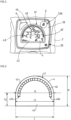
- Fig. 1 represents an embodiment of the front panel 33 of the electronic device 3 housed in the protective covering 1 of a gas container 20 according to the invention, as shown schematically in Fig. 3 , comprising an information display 4 used to display information, data, quantities, etc. useful to the user, in particular pressure, flow, autonomy etc..., as well as icons, alarms...
- the fluid container 20 is here a pressurized gas cylinder, of vertical axis AA, comprising a cylindrical body 29 defining an internal volume for storing gas under high pressure, typically up to 140 to 300 bar abs, or even beyond 300 bar abs, and a neck (not visible) comprising an orifice communicating with the internal volume and allowing the gas to be withdrawn from the internal volume or, conversely, to fill it when it is empty .
- the electronic device 3 is attached to the fluid distribution valve 21, as illustrated in Fig. 5 and Fig. 6 .
- the protective covering 1 comprises a rigid body 2 which is supported on and/or secured to the gas distribution valve 21 and/or to the gas container 20.
- the protective covering 1 is formed of a rigid body 2 formed of two sub-shells 2a, 2b which are connected and secured to each other by sandwiching the housing 34 of the electronic device 3, so as to that it is housed in a first opening 25 of the body 2 of the cowling 1.
- the two sub-shells 2a, 2b also sandwich the fluid distribution valve 21.
- the two sub-shells 2a, 2b can be fixed to each other by screws or the like.
- the gas distribution nozzle 27 and the rotary wheel 22 arranged around the nozzle 27 are housed in a second opening 23 also made in the protective cover 1 rigid protection 1 so as to emerge at the level of the external surface of said cover 1.
- the gas distribution nozzle 21 projects from the center of the rotary steering wheel 22 and projects away towards the outside of the cowling 1.
- the first opening 25 and the second opening 23 are formed “straddling” between the two subshells 2a, 2b.
- the body 2 of the protective covering 1, that is to say its two sub-shells 2a, 2b, can be made of polymer or metal or metal alloy, or both.
- the protective covering 1 is coaxial (axis AA) to the gas bottle 20.
- the protective cover 1 is provided with a carrying handle 7 connected to the cover body 2 by support posts 8.
- the carrying handle 7 surmounts the cover body 2 and faces the front panel 33 of the electronic device 3, as visible on the Fig. 3 .
- the carrying handle 7 is sized to be able to be grasped manually by a user in order to allow easy handling and/or transport of the gas cylinder/RDI/cowl assembly.
- a mobile hanging device or system 9 is also provided (partially visible in Fig. 3 ), preferably pivoting, allowing the gas bottle/RDI/covering assembly to be hung on a support, such as a hospital bed bar, on a stretcher or on a rod or the like.
- a support such as a hospital bed bar
- Such a device or attachment system 9 is known per se.
- an electronic device 3 comprising a rigid housing 34 provided with a front panel 33 carrying a digital display 4, such as a digital screen, for example liquid crystal (LCD) or other, comprising a window and powered electrically by a source of electrical energy (not visible) arranged in the cowling 1, for example one or more batteries or cells arranged in a battery housing arranged in the wall of the body 2 of the cowling and closed by a removable hatch or the like.
- a digital display 4 such as a digital screen, for example liquid crystal (LCD) or other, comprising a window and powered electrically by a source of electrical energy (not visible) arranged in the cowling 1, for example one or more batteries or cells arranged in a battery housing arranged in the wall of the body 2 of the cowling and closed by a removable hatch or the like.
- a source of electrical energy not visible
- the digital display 4 is shaped in a particular manner, namely that it comprises two information display regions 40, 42 comprising a first region 40 in the form of a portion of a disc, for example half-shaped. disc, comprising an arcuate edge 41, and a second region 42 of rectangular shape, as shown schematically in Fig. 2 .
- Such ergonomics or architecture of the digital display 4 is particularly advantageous because it makes it possible to give the user a maximum of useful information on a reduced surface, therefore to reduce the electrical consumption of the display 4 without negatively impacting the readability and/or the number of useful information displayed.
- the first region 40 and the second region 42 are juxtaposed. More precisely, the first region 40 overcomes the second region 42, that is to say that the first region 40 is located at the top of the display 4, while the second region 42 is located at the bottom of the display 4 , when the display 4 is considered in its usual operating position, that is to say positioned as illustrated in Fig. 1 , Fig. 3 Or Fig. 6 .
- the first region 40 comprises an arcuate bar graph 43, of elongated shape, for example in the shape of an arcuate strip (i.e. in the form of an arc of a circle), positioned along the arcuate edge 41, that is to say parallel at the arcuate edge 41 of the first region 40.
- an arcuate bar graph 43 of elongated shape, for example in the shape of an arcuate strip (i.e. in the form of an arc of a circle), positioned along the arcuate edge 41, that is to say parallel at the arcuate edge 41 of the first region 40.
- the bar graph 43 is in color. More precisely, it includes several successive zones of different colors (i.e. colors or shades of colors), for example white, green, red, orange, etc., light or dark.
- the bar graph 43 can include only a single zone or two zones or, conversely, more than 3 successive zones, depending on the chosen embodiment.
- one or more successive zones 140-142 can be formed and/or divided into segments 144, that is to say subdivisions, making it possible to give the user more precise information as to the quantity of gas or residual pressure represented by each zone 140-142.
- Each segment 144 represents a given quantity of gas, preferably a few% of gas, for example of the order of 5%.
- the first region 40 is configured to display (at least) fluid flow information 44, expressed here in L/min) and the second region 42 is configured to display icons or pictograms 46, for example a ringtone icon alert, a wireless communication icon, a battery charge level icon, a gas expiration icon, an icon signifying a gas supply problem, one or more icons relating to the temperature (eg of the device and/or or its environment), an icon meaning that the alert(s) are inhibited, an icon representing a gas flow, an icon representing an hourglass signifying that a task is being processed, an icon signifying that gas is being drawn off by the socket intended for the fans, one or more icons correspond to the different units of measurement of the quantities displayed by the device or any other icon.
- icons or pictograms 46 for example a ringtone icon alert, a wireless communication icon, a battery charge level icon, a gas expiration icon, an icon signifying a gas supply problem, one or more icons relating to the temperature (eg of the device and/or or its environment), an
- the second region further comprises an alphanumeric zone making it possible to display numbers and/or letters.
- first region 40 and the second region 42 are configured to display a fluid autonomy 45, expressed in hours (H) and minutes (Min), as illustrated in Fig. 1 .
- This fluid autonomy information 45 is displayed here “straddling” the first and second regions 40, 42.
- the digital display 4 is configured to display the autonomy information 45 (in H and Min) in digital characters of a size greater than the size of the digital characters used to display the fluid flow information (L/ min) 44 so as to make it more readable and better visible from a distance for the user.
- the digital display 4 comprises a screen of height H between 2.9 and 3.7 cm, and a width L of between 3.9 and 4.3 cm, as shown schematically on the Fig. 2 .
- the first region 40 has a diameter D of between approximately 3 and 5 cm and the second region 42 has a width L1 of between approximately 3 and 5 cm, and a height L2 of between approximately 0.5 and 2 cm, of preferably of the order of 1 cm.
- the width L of the digital display 4 is equal to the diameter D of the first region 40 and the width L1 of the second region 42.
- the front panel 33 of the housing 34 of the electronic measuring device 3 further comprises a button 5 with digital activation, that is to say activated when a user presses it with a finger, such as his index finger, and a indicator light 6, such as an LED diode, also electrically powered by the electrical energy source.
- a button 5 with digital activation that is to say activated when a user presses it with a finger, such as his index finger
- a indicator light 6, such as an LED diode also electrically powered by the electrical energy source.
- This assembly comprising the digital display 4, the button 5 and the indicator light 6 forms an HMI of the electronic measuring device which is housed in the upper part of the cover 1, that is to say under the carrying handle 7 which surmounts the cowling body 2, for better visibility for the user using the gas bottle 20.
- the external surface of the front panel 33, the digital display 4, typically its window, the button 5 and the indicator light 6 are preferably arranged on the same plane, that is to say substantially coplanar, so as to be completely integrated to the body 2 of the cowling 1, i.e. absence of protruding shape, and moreover to facilitate not only visibility but also increase the comfort of use of the HMI by the user.
- the plane of the front panel 33 preferably forms an angle of between 30 and 80° with the vertical axis (AA) of the cowling body 2 and of the bottle 20.
- the digital display 4 is arranged substantially in the center of the front panel 33 of the housing 34 of the electronic measuring device 3 and has a generally rectangular shape with slightly curved peripheral edges, namely an upper edge, a lower edge and two edges peripherals joining the upper and lower edges.
- the button 5 and the indicator light 6, ie LED, are arranged in the front panel 33 above the digital display 4, that is to say in the upper region of the front panel 33 located between the digital display 4 and the upper edge 3a of the front panel 33.
- the button 5 is arranged at the top right of the front panel 33 relative to the digital display 4 and the indicator light 6 is arranged at the top left of the front panel 33 by in relation to the digital display 4, or vice versa, when the cowling 1 is considered in the vertical position, as illustrated in Fig. 3 .
- button 5 may have a general teardrop shape, that is to say rounded. However, other shapes are possible, for example circular, oval or other, including non-rounded shapes.
- the button 5 may include a marking, such as an icon for example, such as here a crossed out bell to indicate to the user that it is an alarm acknowledgment button.
- the indicator light 6 here has a generally substantially triangular shape but other shapes are possible, including non-triangular shapes.
- the digital display 4 makes it possible to display all the information useful to the user, in particular an autonomy 45 (in hours and minutes), a gas flow value 44 (in L/min), as well as the arcuate bar graph 43 representative of the quantity of residual gas, the pictograms 46, eg alarm, electric battery level, active wireless communication or no..., or something else.
- an autonomy 45 in hours and minutes
- a gas flow value 44 in L/min
- the arcuate bar graph 43 representative of the quantity of residual gas
- the pictograms 46 eg alarm, electric battery level, active wireless communication or no..., or something else.
- the digital display 4, the digitally activated button 5 and the indicator light 6 are housed in cutouts or openings provided in the front panel 33 of the box 34 which is itself fixed to the RDI, and also housed in the first opening 25 of the body 2 of the cowling 1.
- Control means are also provided (not shown), such as an electronic card on which a microprocessor is arranged, in particular a microcontroller, implementing one or more calculation algorithms or others and preferably a data storage memory, which are electrically powered by the electrical energy source.
- the control means are arranged in the housing 34 of the electronic measuring device 3.
- the housing 34 is preferably waterproof.
- the control means cooperate with the digital display 4, the digital activation button 5 and the indicator light 6. More precisely, the control means are configured to control the indicator light, that is to say to turn it on in a fixed or intermittent manner, when an alarm is triggered by the control means in response to detection of a quantity of gas in the container 20 less than or equal to a prefixed threshold value, for example memorized by the storage memory data or the like.
- control means calculate, permanently or when requested by the user, in particular the quantity of residual gas or the pressure remaining in the container 20 or the autonomy (i.e. duration during which the device can continue to deliver gas before consumption of the total quantity of gas stored), from measurements or determination of pressure and/or ambient temperature and/or gas or other, obtained for example by means of sensors arranged on or in the RDI (not shown) and/or the withdrawal rate 44 set by the user by means of the rotary wheel 22.
- the measurements taken can in particular be compared to threshold values, that is to say alert values, used to trigger alarms, in particular an almost empty or empty container alarm.
- LEDs preferably intermittently, i.e. LED flashing, to indicate a bottle 20 almost empty, or in a fixed manner , i.e. LED permanently lit, to indicate a completely empty bottle, therefore unusable.
- control means can also simultaneously trigger one or more audible alarms, such as a “beep” to attract the user's attention.
- audible alarms such as a “beep”
- control means simultaneously control the triggering of an audible alert signal and the lighting of the indicator light, i.e. LED 6, in the event of activation of an alarm, that is to say that the audible alert signal and the indicator light are synchronous and activate (or deactivate) at the same time.
- the button 5 can also be configured to cooperate with the control means to scroll through data/information or menus displayed on the digital display 4, in particular data/information or stored menus by the storage memory.
- the configuration of the display 4 of the housing 34 of the electronic measuring device 3 fitted to a container 1 according to the invention allows the user to know easily and from a distance, that is to say from 1 to 2 meters, if the container 20 still contains or does not contain sufficient fluid under pressure because, on the one hand, the information available on the screen 4 is easily readable and, on the other hand, an empty or almost empty container 20 is immediately reported to it by the triggering of a specific alarm which materializes in particular by the lighting of the LED 6, for example a flashing of LED 6, and possibly an audible signal as explained above.
- the user does not need to “wake up” the screen 4 if it is in standby mode, in order to be able to have this information relating to the filling of the container 20.
- the fact of having the button 5 arranged at the top of the display 4, in the front panel 3 of the electronic measuring device 3, allows the user to have easy access to this digitally activated button 5, therefore being able to easily, for example, acknowledge an alarm, scroll through menus or information on the screen of the display 4 or display specific information.
- a fluid container 20, in particular a gas bottle, equipped with a tap, such as an RDI, protected by a covering 1 according to the invention is suitable for storing and supplying gas under pressure , in particular a medical gas or gas mixture, such as oxygen, a NO/N 2 , O 2 /N 2 O or He/O 2 mixture, air or other.
- a medical gas or gas mixture such as oxygen, a NO/N 2 , O 2 /N 2 O or He/O 2 mixture, air or other.
Landscapes
- Engineering & Computer Science (AREA)
- Mechanical Engineering (AREA)
- General Engineering & Computer Science (AREA)
- Filling Or Discharging Of Gas Storage Vessels (AREA)
- Measuring Fluid Pressure (AREA)
- Measuring Volume Flow (AREA)
Claims (12)
- Gasbehälter (20), der ein Gasabgabeventil (21) und eine elektronische Messvorrichtung (3), die auf dem Gasabgabeventil (21) angeordnet ist, beinhaltet, wobei die elektronische Messvorrichtung (3) ein Gehäuse (34) beinhaltet, das eine Frontplatte (33) beinhaltet, die ein digitales Display (4) beinhaltet, wobei das digitale Display (4) mindestens zwei nebeneinanderliegende Bereiche zur Anzeige von Informationen (40, 42) beinhaltet, die Folgendes beinhalten:- einen ersten Bereich (40) in Form eines Kreisscheibenabschnitts, der einen kreisbogenförmigen Rand (41) und eine bogenförmige Balkenanzeige (43), die entlang des kreisbogenförmigen Randes (41) positioniert ist, beinhaltet, und- einen zweiten Bereich (42) mit rechteckiger Form, dadurch gekennzeichnet, dass die elektronische Messvorrichtung (3) ferner einen mit dem Finger aktivierbaren Knopf (5) und eine Kontrollleuchte (6) beinhaltet, die in der Frontplatte (33) angeordnet sind, wobei das digitale Display (4) in der Mitte der Frontplatte (33) der elektronischen Messvorrichtung (3) angeordnet ist und der Knopf (5) und die Kontrollleuchte (6) oberhalb des digitalen Displays (4) angeordnet sind.
- Behälter nach Anspruch 1, dadurch gekennzeichnet, dass der erste Bereich (40) des digitalen Displays (4) eine bogenförmige Balkenanzeige (43), die entlang des kreisbogenförmigen Randes (41) angeordnet ist, vorzugsweise eine farbige Balkenanzeige (43), beinhaltet.
- Behälter nach Anspruch 2, dadurch gekennzeichnet, dass die bogenförmige Balkenanzeige (43) ein Anfangs- und ein Abschlussende (43a, 43b) beinhaltet, die sich in dem zweiten Bereich (42) mit rechteckiger Form befinden.
- Behälter nach einem der vorhergehenden Ansprüche, dadurch gekennzeichnet, dass:- der erste Bereich (40) dazu konfiguriert ist, mindestens eine Information über einen Fluiddurchfluss (ausgedrückt in l/min) anzuzeigen, und/oder- der zweite Bereich (42) dazu konfiguriert ist, mindestens Symbole anzuzeigen.
- Behälter nach einem der vorhergehenden Ansprüche, dadurch gekennzeichnet, dass der erste Bereich (40) und/oder der zweite Bereich (42) dazu konfiguriert sind, eine Fluidrestlaufzeit (ausgedrückt in h und min) anzuzeigen.
- Behälter nach einem der Ansprüche 2 oder 3, dadurch gekennzeichnet, dass die Balkenanzeige (43) mehrere aufeinanderfolgende Zonen (140-142) beinhaltet, die jeweils in mehrere Segmente (144) unterteilt sind.
- Behälter nach einem der vorhergehenden Ansprüche, dadurch gekennzeichnet, dass das digitale Display (4) einen Bildschirm mit einer Höhe (H) zwischen 2,9 und 3,7 cm und einer Länge (D) zwischen 3,9 und 4,3 cm beinhaltet.
- Behälter nach einem der vorhergehenden Ansprüche, dadurch gekennzeichnet, dass er ferner eine Schutzabdeckung (1) beinhaltet, die um das Fluidabgabeventil (21) angeordnet ist, wobei die elektronische Messvorrichtung (3) in einer ersten Öffnung (25), die in dem Körper (2) der Schutzabdeckung (1) eingerichtet ist, aufgenommen ist.
- Behälter nach einem der vorhergehenden Ansprüche, dadurch gekennzeichnet, dass er aus Gasflaschen ausgewählt ist.
- Behälter nach einem der vorhergehenden Ansprüche, dadurch gekennzeichnet, dass das Fluidabgabeventil (21) ein VIPR ist.
- Behälter nach einem der vorhergehenden Ansprüche, dadurch gekennzeichnet, dass er ferner mindestens eine elektrische Stromquelle beinhaltet, die mindestens das digitale Display (4) mit Strom versorgt.
- Verwendung eines Gasbehälters (20), insbesondere einer Gasflasche, nach einem der vorhergehenden Ansprüche, um ein Druckgas zu speichern oder bereitzustellen.
Applications Claiming Priority (1)
| Application Number | Priority Date | Filing Date | Title |
|---|---|---|---|
| FR2000294A FR3106188B1 (fr) | 2020-01-14 | 2020-01-14 | Récipient de fluide comprenant un dispositif de mesure électronique à afficheur numérique amélioré |
Publications (3)
| Publication Number | Publication Date |
|---|---|
| EP3851733A1 EP3851733A1 (de) | 2021-07-21 |
| EP3851733B1 true EP3851733B1 (de) | 2024-07-03 |
| EP3851733C0 EP3851733C0 (de) | 2024-07-03 |
Family
ID=70008877
Family Applications (1)
| Application Number | Title | Priority Date | Filing Date |
|---|---|---|---|
| EP20202685.2A Active EP3851733B1 (de) | 2020-01-14 | 2020-10-20 | Flüssigkeitsbehälter, der eine elektronische messanzeige mit verbessertem digitalen display umfasst |
Country Status (3)
| Country | Link |
|---|---|
| EP (1) | EP3851733B1 (de) |
| ES (1) | ES2988446T3 (de) |
| FR (1) | FR3106188B1 (de) |
Families Citing this family (4)
| Publication number | Priority date | Publication date | Assignee | Title |
|---|---|---|---|---|
| US11415449B2 (en) * | 2020-04-15 | 2022-08-16 | Worthington Cylinders Corporation | Cylinder attachment |
| USD981528S1 (en) | 2020-04-15 | 2023-03-21 | Worthington Cylinders Corporation | Canister attachment device |
| USD986752S1 (en) | 2020-08-25 | 2023-05-23 | Worthington Cylinders Corporation | Digital canister gauge |
| FR3133320B1 (fr) | 2022-03-10 | 2024-08-23 | Air Liquide | Robinet pour récipient de gaz à détendeur intégré amélioré |
Family Cites Families (6)
| Publication number | Priority date | Publication date | Assignee | Title |
|---|---|---|---|---|
| GB0922355D0 (en) * | 2009-12-21 | 2010-02-03 | Linde Ag | Pressure vessel |
| US10151405B1 (en) * | 2012-11-09 | 2018-12-11 | Praxair Technology, Inc. | Valve integrated pressure regulator with shroud and digital display for gas cylinders |
| FR3018584B1 (fr) | 2014-03-12 | 2016-04-15 | Air Liquide | Capotage de protection avec systeme d’accrochage pivotant pour bouteille de gaz |
| FR3018583B1 (fr) | 2014-03-12 | 2017-01-27 | Air Liquide | Capotage de protection pour bouteille de gaz avec ecran d’affichage electronique en position haute |
| FR3026158B1 (fr) | 2014-09-22 | 2017-07-21 | Air Liquide | Recipient de gaz avec bloc robinet equipe d'un ecran tactile d'affichage d'informations |
| FR3033385A1 (fr) * | 2015-03-05 | 2016-09-09 | Air Liquide | Recipient de gaz avec dispositif de visualisation de la quantite residuelle de gaz |
-
2020
- 2020-01-14 FR FR2000294A patent/FR3106188B1/fr active Active
- 2020-10-20 EP EP20202685.2A patent/EP3851733B1/de active Active
- 2020-10-20 ES ES20202685T patent/ES2988446T3/es active Active
Also Published As
| Publication number | Publication date |
|---|---|
| ES2988446T3 (es) | 2024-11-20 |
| EP3851733C0 (de) | 2024-07-03 |
| FR3106188B1 (fr) | 2023-08-25 |
| EP3851733A1 (de) | 2021-07-21 |
| FR3106188A1 (fr) | 2021-07-16 |
Similar Documents
| Publication | Publication Date | Title |
|---|---|---|
| EP3851733A1 (de) | Flüssigkeitsbehälter, der eine elektronische messanzeige mit verbessertem digitalen display umfasst | |
| EP2918892B1 (de) | Schutzhaube für Gasflasche mit elektronischem Anzeigebildschirm in oberer Position | |
| EP3002498B1 (de) | Gasbehälter mit absperrhahnblock, der mit einem berührungsbildschirm zur datenanzeige ausgestattet ist | |
| EP4027051B1 (de) | Gasbehälter, der mit einer elektronischen messvorrichtung ausgestattet ist | |
| EP4071400B1 (de) | Druckbehälter für fluide mit elektronischer vorrichtung zur berechnung der fluidmenge | |
| EP3913276B1 (de) | Druckgasbehälter, der mit einer elektronischen vorrichtung mit mitteln zur bestätigung von alarmen ausgestattet ist | |
| CA3096467A1 (fr) | Recipient de fluide a afficheur numerique donnant une indication de l'etat du recipient | |
| FR3033385A1 (fr) | Recipient de gaz avec dispositif de visualisation de la quantite residuelle de gaz | |
| FR3112192A1 (fr) | Récipient de fluide sous pression avec dispositif électronique embarquant un capteur de pression et température | |
| EP3875837B1 (de) | Gasdruckbehälter mit elektronischer vorrichtung zur automatischen berechnung des verfallsdatums des gases. | |
| EP3380817B1 (de) | Oxy-acetylen-arbeitsvorrichtung und verfahren zur bestimmung der betriebszeit der besagten vorrichtung | |
| EP4071399B1 (de) | Druckgasbehälter mit verteilventil und elektronischer vorrichtung, die die verwendung eines medizinischen beatmungsgeräts anzeigt | |
| FR3106186A1 (fr) | Récipient de gaz équipé d’un dispositif de mesure électronique portant une IHM | |
| EP3882507B1 (de) | Druckgasbehälter, der mit einer elektronischen vorrichtung zur warnung bei abklemmung ausgestattet ist | |
| FR3112839A1 (fr) | Récipient de fluide sous pression avec dispositif électronique permettant de calculer l’autonomie de manière plus précise | |
| EP3851732B1 (de) | Gasbehälter mit anzeige der durchsatzmenge und des entsprechenden füllstands | |
| EP4403818B1 (de) | Flüssigkeitsbehälter mit einem verteilerhahn mit elektronischer vorrichtung und unabhängigem drucksensor | |
| EP3754245A1 (de) | Gasbehälter mit anzeige der entsprechenden möglichen durchsatzmengen und reichweiten | |
| CA3170082A1 (fr) | Dispositif et procede de suivi de l'observance d'un traitement therapeutique ophtalmique | |
| EP4542103A1 (de) | Flüssigkeitsbehälter mit einem verteilerhahn mit einer elektronischen vorrichtung, die durch eine schutzabdeckung gehalten wird | |
| FR3113106A1 (fr) | Récipient de fluide sous pression avec dispositif électronique à système d'endormissement et de réveil des moyens de communication avec l’extérieur | |
| EP4545841A1 (de) | Druckflüssigkeitsbehälter mit elektronischer vorrichtung und erkennung von temperatursensorfehlfunktion |
Legal Events
| Date | Code | Title | Description |
|---|---|---|---|
| PUAI | Public reference made under article 153(3) epc to a published international application that has entered the european phase |
Free format text: ORIGINAL CODE: 0009012 |
|
| STAA | Information on the status of an ep patent application or granted ep patent |
Free format text: STATUS: THE APPLICATION HAS BEEN PUBLISHED |
|
| AK | Designated contracting states |
Kind code of ref document: A1 Designated state(s): AL AT BE BG CH CY CZ DE DK EE ES FI FR GB GR HR HU IE IS IT LI LT LU LV MC MK MT NL NO PL PT RO RS SE SI SK SM TR |
|
| STAA | Information on the status of an ep patent application or granted ep patent |
Free format text: STATUS: REQUEST FOR EXAMINATION WAS MADE |
|
| 17P | Request for examination filed |
Effective date: 20220121 |
|
| RBV | Designated contracting states (corrected) |
Designated state(s): AL AT BE BG CH CY CZ DE DK EE ES FI FR GB GR HR HU IE IS IT LI LT LU LV MC MK MT NL NO PL PT RO RS SE SI SK SM TR |
|
| RAP3 | Party data changed (applicant data changed or rights of an application transferred) |
Owner name: L'AIR LIQUIDE, SOCIETE ANONYME POUR L'ETUDE ET L'EXPLOITATION DES PROCEDES GEORGES CLAUDE |
|
| GRAP | Despatch of communication of intention to grant a patent |
Free format text: ORIGINAL CODE: EPIDOSNIGR1 |
|
| STAA | Information on the status of an ep patent application or granted ep patent |
Free format text: STATUS: GRANT OF PATENT IS INTENDED |
|
| INTG | Intention to grant announced |
Effective date: 20240227 |
|
| GRAS | Grant fee paid |
Free format text: ORIGINAL CODE: EPIDOSNIGR3 |
|
| GRAA | (expected) grant |
Free format text: ORIGINAL CODE: 0009210 |
|
| STAA | Information on the status of an ep patent application or granted ep patent |
Free format text: STATUS: THE PATENT HAS BEEN GRANTED |
|
| AK | Designated contracting states |
Kind code of ref document: B1 Designated state(s): AL AT BE BG CH CY CZ DE DK EE ES FI FR GB GR HR HU IE IS IT LI LT LU LV MC MK MT NL NO PL PT RO RS SE SI SK SM TR |
|
| REG | Reference to a national code |
Ref country code: CH Ref legal event code: EP |
|
| REG | Reference to a national code |
Ref country code: DE Ref legal event code: R096 Ref document number: 602020033227 Country of ref document: DE |
|
| U01 | Request for unitary effect filed |
Effective date: 20240709 |
|
| U07 | Unitary effect registered |
Designated state(s): AT BE BG DE DK EE FI FR IT LT LU LV MT NL PT SE SI Effective date: 20240719 |
|
| REG | Reference to a national code |
Ref country code: ES Ref legal event code: FG2A Ref document number: 2988446 Country of ref document: ES Kind code of ref document: T3 Effective date: 20241120 |
|
| U20 | Renewal fee for the european patent with unitary effect paid |
Year of fee payment: 5 Effective date: 20241025 |
|
| PG25 | Lapsed in a contracting state [announced via postgrant information from national office to epo] |
Ref country code: NO Free format text: LAPSE BECAUSE OF FAILURE TO SUBMIT A TRANSLATION OF THE DESCRIPTION OR TO PAY THE FEE WITHIN THE PRESCRIBED TIME-LIMIT Effective date: 20241003 |
|
| PG25 | Lapsed in a contracting state [announced via postgrant information from national office to epo] |
Ref country code: GR Free format text: LAPSE BECAUSE OF FAILURE TO SUBMIT A TRANSLATION OF THE DESCRIPTION OR TO PAY THE FEE WITHIN THE PRESCRIBED TIME-LIMIT Effective date: 20241004 Ref country code: PL Free format text: LAPSE BECAUSE OF FAILURE TO SUBMIT A TRANSLATION OF THE DESCRIPTION OR TO PAY THE FEE WITHIN THE PRESCRIBED TIME-LIMIT Effective date: 20240703 |
|
| PG25 | Lapsed in a contracting state [announced via postgrant information from national office to epo] |
Ref country code: IS Free format text: LAPSE BECAUSE OF FAILURE TO SUBMIT A TRANSLATION OF THE DESCRIPTION OR TO PAY THE FEE WITHIN THE PRESCRIBED TIME-LIMIT Effective date: 20241103 |
|
| PG25 | Lapsed in a contracting state [announced via postgrant information from national office to epo] |
Ref country code: HR Free format text: LAPSE BECAUSE OF FAILURE TO SUBMIT A TRANSLATION OF THE DESCRIPTION OR TO PAY THE FEE WITHIN THE PRESCRIBED TIME-LIMIT Effective date: 20240703 Ref country code: CZ Free format text: LAPSE BECAUSE OF FAILURE TO SUBMIT A TRANSLATION OF THE DESCRIPTION OR TO PAY THE FEE WITHIN THE PRESCRIBED TIME-LIMIT Effective date: 20240703 |
|
| PG25 | Lapsed in a contracting state [announced via postgrant information from national office to epo] |
Ref country code: RS Free format text: LAPSE BECAUSE OF FAILURE TO SUBMIT A TRANSLATION OF THE DESCRIPTION OR TO PAY THE FEE WITHIN THE PRESCRIBED TIME-LIMIT Effective date: 20241003 |
|
| PG25 | Lapsed in a contracting state [announced via postgrant information from national office to epo] |
Ref country code: RS Free format text: LAPSE BECAUSE OF FAILURE TO SUBMIT A TRANSLATION OF THE DESCRIPTION OR TO PAY THE FEE WITHIN THE PRESCRIBED TIME-LIMIT Effective date: 20241003 Ref country code: PL Free format text: LAPSE BECAUSE OF FAILURE TO SUBMIT A TRANSLATION OF THE DESCRIPTION OR TO PAY THE FEE WITHIN THE PRESCRIBED TIME-LIMIT Effective date: 20240703 Ref country code: NO Free format text: LAPSE BECAUSE OF FAILURE TO SUBMIT A TRANSLATION OF THE DESCRIPTION OR TO PAY THE FEE WITHIN THE PRESCRIBED TIME-LIMIT Effective date: 20241003 Ref country code: IS Free format text: LAPSE BECAUSE OF FAILURE TO SUBMIT A TRANSLATION OF THE DESCRIPTION OR TO PAY THE FEE WITHIN THE PRESCRIBED TIME-LIMIT Effective date: 20241103 Ref country code: HR Free format text: LAPSE BECAUSE OF FAILURE TO SUBMIT A TRANSLATION OF THE DESCRIPTION OR TO PAY THE FEE WITHIN THE PRESCRIBED TIME-LIMIT Effective date: 20240703 Ref country code: GR Free format text: LAPSE BECAUSE OF FAILURE TO SUBMIT A TRANSLATION OF THE DESCRIPTION OR TO PAY THE FEE WITHIN THE PRESCRIBED TIME-LIMIT Effective date: 20241004 Ref country code: CZ Free format text: LAPSE BECAUSE OF FAILURE TO SUBMIT A TRANSLATION OF THE DESCRIPTION OR TO PAY THE FEE WITHIN THE PRESCRIBED TIME-LIMIT Effective date: 20240703 |
|
| PG25 | Lapsed in a contracting state [announced via postgrant information from national office to epo] |
Ref country code: SM Free format text: LAPSE BECAUSE OF FAILURE TO SUBMIT A TRANSLATION OF THE DESCRIPTION OR TO PAY THE FEE WITHIN THE PRESCRIBED TIME-LIMIT Effective date: 20240703 |
|
| PG25 | Lapsed in a contracting state [announced via postgrant information from national office to epo] |
Ref country code: SK Free format text: LAPSE BECAUSE OF FAILURE TO SUBMIT A TRANSLATION OF THE DESCRIPTION OR TO PAY THE FEE WITHIN THE PRESCRIBED TIME-LIMIT Effective date: 20240703 |
|
| PLBE | No opposition filed within time limit |
Free format text: ORIGINAL CODE: 0009261 |
|
| STAA | Information on the status of an ep patent application or granted ep patent |
Free format text: STATUS: NO OPPOSITION FILED WITHIN TIME LIMIT |
|
| 26N | No opposition filed |
Effective date: 20250404 |
|
| GBPC | Gb: european patent ceased through non-payment of renewal fee |
Effective date: 20241020 |
|
| PG25 | Lapsed in a contracting state [announced via postgrant information from national office to epo] |
Ref country code: MC Free format text: LAPSE BECAUSE OF FAILURE TO SUBMIT A TRANSLATION OF THE DESCRIPTION OR TO PAY THE FEE WITHIN THE PRESCRIBED TIME-LIMIT Effective date: 20240703 |
|
| PG25 | Lapsed in a contracting state [announced via postgrant information from national office to epo] |
Ref country code: GB Free format text: LAPSE BECAUSE OF NON-PAYMENT OF DUE FEES Effective date: 20241020 |
|
| PG25 | Lapsed in a contracting state [announced via postgrant information from national office to epo] |
Ref country code: IE Free format text: LAPSE BECAUSE OF NON-PAYMENT OF DUE FEES Effective date: 20241020 |
|
| REG | Reference to a national code |
Ref country code: CH Ref legal event code: U11 Free format text: ST27 STATUS EVENT CODE: U-0-0-U10-U11 (AS PROVIDED BY THE NATIONAL OFFICE) Effective date: 20251101 |
|
| PG25 | Lapsed in a contracting state [announced via postgrant information from national office to epo] |
Ref country code: RO Free format text: LAPSE BECAUSE OF FAILURE TO SUBMIT A TRANSLATION OF THE DESCRIPTION OR TO PAY THE FEE WITHIN THE PRESCRIBED TIME-LIMIT Effective date: 20240703 |
|
| U20 | Renewal fee for the european patent with unitary effect paid |
Year of fee payment: 6 Effective date: 20251028 |
|
| PGFP | Annual fee paid to national office [announced via postgrant information from national office to epo] |
Ref country code: CH Payment date: 20251101 Year of fee payment: 6 |
|
| PG25 | Lapsed in a contracting state [announced via postgrant information from national office to epo] |
Ref country code: CY Free format text: LAPSE BECAUSE OF FAILURE TO SUBMIT A TRANSLATION OF THE DESCRIPTION OR TO PAY THE FEE WITHIN THE PRESCRIBED TIME-LIMIT; INVALID AB INITIO Effective date: 20201020 |
|
| PGFP | Annual fee paid to national office [announced via postgrant information from national office to epo] |
Ref country code: ES Payment date: 20251216 Year of fee payment: 6 |
|
| PG25 | Lapsed in a contracting state [announced via postgrant information from national office to epo] |
Ref country code: HU Free format text: LAPSE BECAUSE OF FAILURE TO SUBMIT A TRANSLATION OF THE DESCRIPTION OR TO PAY THE FEE WITHIN THE PRESCRIBED TIME-LIMIT; INVALID AB INITIO Effective date: 20201020 |