EP4542103A1 - Flüssigkeitsbehälter mit einem verteilerhahn mit einer elektronischen vorrichtung, die durch eine schutzabdeckung gehalten wird - Google Patents
Flüssigkeitsbehälter mit einem verteilerhahn mit einer elektronischen vorrichtung, die durch eine schutzabdeckung gehalten wird Download PDFInfo
- Publication number
- EP4542103A1 EP4542103A1 EP24201943.8A EP24201943A EP4542103A1 EP 4542103 A1 EP4542103 A1 EP 4542103A1 EP 24201943 A EP24201943 A EP 24201943A EP 4542103 A1 EP4542103 A1 EP 4542103A1
- Authority
- EP
- European Patent Office
- Prior art keywords
- housing
- electronic device
- protective cover
- gas
- opening
- Prior art date
- Legal status (The legal status is an assumption and is not a legal conclusion. Google has not performed a legal analysis and makes no representation as to the accuracy of the status listed.)
- Pending
Links
Images

Classifications
-
- F—MECHANICAL ENGINEERING; LIGHTING; HEATING; WEAPONS; BLASTING
- F17—STORING OR DISTRIBUTING GASES OR LIQUIDS
- F17C—VESSELS FOR CONTAINING OR STORING COMPRESSED, LIQUEFIED OR SOLIDIFIED GASES; FIXED-CAPACITY GAS-HOLDERS; FILLING VESSELS WITH, OR DISCHARGING FROM VESSELS, COMPRESSED, LIQUEFIED, OR SOLIDIFIED GASES
- F17C13/00—Details of vessels or of the filling or discharging of vessels
- F17C13/04—Arrangement or mounting of valves
-
- F—MECHANICAL ENGINEERING; LIGHTING; HEATING; WEAPONS; BLASTING
- F17—STORING OR DISTRIBUTING GASES OR LIQUIDS
- F17C—VESSELS FOR CONTAINING OR STORING COMPRESSED, LIQUEFIED OR SOLIDIFIED GASES; FIXED-CAPACITY GAS-HOLDERS; FILLING VESSELS WITH, OR DISCHARGING FROM VESSELS, COMPRESSED, LIQUEFIED, OR SOLIDIFIED GASES
- F17C13/00—Details of vessels or of the filling or discharging of vessels
- F17C13/02—Special adaptations of indicating, measuring, or monitoring equipment
- F17C13/025—Special adaptations of indicating, measuring, or monitoring equipment having the pressure as the parameter
-
- F—MECHANICAL ENGINEERING; LIGHTING; HEATING; WEAPONS; BLASTING
- F17—STORING OR DISTRIBUTING GASES OR LIQUIDS
- F17C—VESSELS FOR CONTAINING OR STORING COMPRESSED, LIQUEFIED OR SOLIDIFIED GASES; FIXED-CAPACITY GAS-HOLDERS; FILLING VESSELS WITH, OR DISCHARGING FROM VESSELS, COMPRESSED, LIQUEFIED, OR SOLIDIFIED GASES
- F17C2201/00—Vessel construction, in particular geometry, arrangement or size
- F17C2201/01—Shape
- F17C2201/0104—Shape cylindrical
-
- F—MECHANICAL ENGINEERING; LIGHTING; HEATING; WEAPONS; BLASTING
- F17—STORING OR DISTRIBUTING GASES OR LIQUIDS
- F17C—VESSELS FOR CONTAINING OR STORING COMPRESSED, LIQUEFIED OR SOLIDIFIED GASES; FIXED-CAPACITY GAS-HOLDERS; FILLING VESSELS WITH, OR DISCHARGING FROM VESSELS, COMPRESSED, LIQUEFIED, OR SOLIDIFIED GASES
- F17C2201/00—Vessel construction, in particular geometry, arrangement or size
- F17C2201/03—Orientation
- F17C2201/032—Orientation with substantially vertical main axis
-
- F—MECHANICAL ENGINEERING; LIGHTING; HEATING; WEAPONS; BLASTING
- F17—STORING OR DISTRIBUTING GASES OR LIQUIDS
- F17C—VESSELS FOR CONTAINING OR STORING COMPRESSED, LIQUEFIED OR SOLIDIFIED GASES; FIXED-CAPACITY GAS-HOLDERS; FILLING VESSELS WITH, OR DISCHARGING FROM VESSELS, COMPRESSED, LIQUEFIED, OR SOLIDIFIED GASES
- F17C2201/00—Vessel construction, in particular geometry, arrangement or size
- F17C2201/05—Size
- F17C2201/058—Size portable (<30 l)
-
- F—MECHANICAL ENGINEERING; LIGHTING; HEATING; WEAPONS; BLASTING
- F17—STORING OR DISTRIBUTING GASES OR LIQUIDS
- F17C—VESSELS FOR CONTAINING OR STORING COMPRESSED, LIQUEFIED OR SOLIDIFIED GASES; FIXED-CAPACITY GAS-HOLDERS; FILLING VESSELS WITH, OR DISCHARGING FROM VESSELS, COMPRESSED, LIQUEFIED, OR SOLIDIFIED GASES
- F17C2203/00—Vessel construction, in particular walls or details thereof
- F17C2203/06—Materials for walls or layers thereof; Properties or structures of walls or their materials
- F17C2203/0634—Materials for walls or layers thereof
- F17C2203/0636—Metals
-
- F—MECHANICAL ENGINEERING; LIGHTING; HEATING; WEAPONS; BLASTING
- F17—STORING OR DISTRIBUTING GASES OR LIQUIDS
- F17C—VESSELS FOR CONTAINING OR STORING COMPRESSED, LIQUEFIED OR SOLIDIFIED GASES; FIXED-CAPACITY GAS-HOLDERS; FILLING VESSELS WITH, OR DISCHARGING FROM VESSELS, COMPRESSED, LIQUEFIED, OR SOLIDIFIED GASES
- F17C2203/00—Vessel construction, in particular walls or details thereof
- F17C2203/06—Materials for walls or layers thereof; Properties or structures of walls or their materials
- F17C2203/0634—Materials for walls or layers thereof
- F17C2203/0636—Metals
- F17C2203/0639—Steels
-
- F—MECHANICAL ENGINEERING; LIGHTING; HEATING; WEAPONS; BLASTING
- F17—STORING OR DISTRIBUTING GASES OR LIQUIDS
- F17C—VESSELS FOR CONTAINING OR STORING COMPRESSED, LIQUEFIED OR SOLIDIFIED GASES; FIXED-CAPACITY GAS-HOLDERS; FILLING VESSELS WITH, OR DISCHARGING FROM VESSELS, COMPRESSED, LIQUEFIED, OR SOLIDIFIED GASES
- F17C2203/00—Vessel construction, in particular walls or details thereof
- F17C2203/06—Materials for walls or layers thereof; Properties or structures of walls or their materials
- F17C2203/0634—Materials for walls or layers thereof
- F17C2203/0636—Metals
- F17C2203/0646—Aluminium
-
- F—MECHANICAL ENGINEERING; LIGHTING; HEATING; WEAPONS; BLASTING
- F17—STORING OR DISTRIBUTING GASES OR LIQUIDS
- F17C—VESSELS FOR CONTAINING OR STORING COMPRESSED, LIQUEFIED OR SOLIDIFIED GASES; FIXED-CAPACITY GAS-HOLDERS; FILLING VESSELS WITH, OR DISCHARGING FROM VESSELS, COMPRESSED, LIQUEFIED, OR SOLIDIFIED GASES
- F17C2203/00—Vessel construction, in particular walls or details thereof
- F17C2203/06—Materials for walls or layers thereof; Properties or structures of walls or their materials
- F17C2203/0634—Materials for walls or layers thereof
- F17C2203/0658—Synthetics
-
- F—MECHANICAL ENGINEERING; LIGHTING; HEATING; WEAPONS; BLASTING
- F17—STORING OR DISTRIBUTING GASES OR LIQUIDS
- F17C—VESSELS FOR CONTAINING OR STORING COMPRESSED, LIQUEFIED OR SOLIDIFIED GASES; FIXED-CAPACITY GAS-HOLDERS; FILLING VESSELS WITH, OR DISCHARGING FROM VESSELS, COMPRESSED, LIQUEFIED, OR SOLIDIFIED GASES
- F17C2203/00—Vessel construction, in particular walls or details thereof
- F17C2203/06—Materials for walls or layers thereof; Properties or structures of walls or their materials
- F17C2203/0634—Materials for walls or layers thereof
- F17C2203/0658—Synthetics
- F17C2203/0663—Synthetics in form of fibers or filaments
-
- F—MECHANICAL ENGINEERING; LIGHTING; HEATING; WEAPONS; BLASTING
- F17—STORING OR DISTRIBUTING GASES OR LIQUIDS
- F17C—VESSELS FOR CONTAINING OR STORING COMPRESSED, LIQUEFIED OR SOLIDIFIED GASES; FIXED-CAPACITY GAS-HOLDERS; FILLING VESSELS WITH, OR DISCHARGING FROM VESSELS, COMPRESSED, LIQUEFIED, OR SOLIDIFIED GASES
- F17C2205/00—Vessel construction, in particular mounting arrangements, attachments or identifications means
- F17C2205/01—Mounting arrangements
- F17C2205/0153—Details of mounting arrangements
- F17C2205/0157—Details of mounting arrangements for transport
- F17C2205/0165—Details of mounting arrangements for transport with handgrip
-
- F—MECHANICAL ENGINEERING; LIGHTING; HEATING; WEAPONS; BLASTING
- F17—STORING OR DISTRIBUTING GASES OR LIQUIDS
- F17C—VESSELS FOR CONTAINING OR STORING COMPRESSED, LIQUEFIED OR SOLIDIFIED GASES; FIXED-CAPACITY GAS-HOLDERS; FILLING VESSELS WITH, OR DISCHARGING FROM VESSELS, COMPRESSED, LIQUEFIED, OR SOLIDIFIED GASES
- F17C2205/00—Vessel construction, in particular mounting arrangements, attachments or identifications means
- F17C2205/01—Mounting arrangements
- F17C2205/0153—Details of mounting arrangements
- F17C2205/0188—Hanging up devices
-
- F—MECHANICAL ENGINEERING; LIGHTING; HEATING; WEAPONS; BLASTING
- F17—STORING OR DISTRIBUTING GASES OR LIQUIDS
- F17C—VESSELS FOR CONTAINING OR STORING COMPRESSED, LIQUEFIED OR SOLIDIFIED GASES; FIXED-CAPACITY GAS-HOLDERS; FILLING VESSELS WITH, OR DISCHARGING FROM VESSELS, COMPRESSED, LIQUEFIED, OR SOLIDIFIED GASES
- F17C2205/00—Vessel construction, in particular mounting arrangements, attachments or identifications means
- F17C2205/03—Fluid connections, filters, valves, closure means or other attachments
- F17C2205/0302—Fittings, valves, filters, or components in connection with the gas storage device
- F17C2205/0305—Bosses, e.g. boss collars
-
- F—MECHANICAL ENGINEERING; LIGHTING; HEATING; WEAPONS; BLASTING
- F17—STORING OR DISTRIBUTING GASES OR LIQUIDS
- F17C—VESSELS FOR CONTAINING OR STORING COMPRESSED, LIQUEFIED OR SOLIDIFIED GASES; FIXED-CAPACITY GAS-HOLDERS; FILLING VESSELS WITH, OR DISCHARGING FROM VESSELS, COMPRESSED, LIQUEFIED, OR SOLIDIFIED GASES
- F17C2205/00—Vessel construction, in particular mounting arrangements, attachments or identifications means
- F17C2205/03—Fluid connections, filters, valves, closure means or other attachments
- F17C2205/0302—Fittings, valves, filters, or components in connection with the gas storage device
- F17C2205/0308—Protective caps
-
- F—MECHANICAL ENGINEERING; LIGHTING; HEATING; WEAPONS; BLASTING
- F17—STORING OR DISTRIBUTING GASES OR LIQUIDS
- F17C—VESSELS FOR CONTAINING OR STORING COMPRESSED, LIQUEFIED OR SOLIDIFIED GASES; FIXED-CAPACITY GAS-HOLDERS; FILLING VESSELS WITH, OR DISCHARGING FROM VESSELS, COMPRESSED, LIQUEFIED, OR SOLIDIFIED GASES
- F17C2205/00—Vessel construction, in particular mounting arrangements, attachments or identifications means
- F17C2205/03—Fluid connections, filters, valves, closure means or other attachments
- F17C2205/0302—Fittings, valves, filters, or components in connection with the gas storage device
- F17C2205/0323—Valves
- F17C2205/0326—Valves electrically actuated
-
- F—MECHANICAL ENGINEERING; LIGHTING; HEATING; WEAPONS; BLASTING
- F17—STORING OR DISTRIBUTING GASES OR LIQUIDS
- F17C—VESSELS FOR CONTAINING OR STORING COMPRESSED, LIQUEFIED OR SOLIDIFIED GASES; FIXED-CAPACITY GAS-HOLDERS; FILLING VESSELS WITH, OR DISCHARGING FROM VESSELS, COMPRESSED, LIQUEFIED, OR SOLIDIFIED GASES
- F17C2205/00—Vessel construction, in particular mounting arrangements, attachments or identifications means
- F17C2205/03—Fluid connections, filters, valves, closure means or other attachments
- F17C2205/0302—Fittings, valves, filters, or components in connection with the gas storage device
- F17C2205/0323—Valves
- F17C2205/0329—Valves manually actuated
-
- F—MECHANICAL ENGINEERING; LIGHTING; HEATING; WEAPONS; BLASTING
- F17—STORING OR DISTRIBUTING GASES OR LIQUIDS
- F17C—VESSELS FOR CONTAINING OR STORING COMPRESSED, LIQUEFIED OR SOLIDIFIED GASES; FIXED-CAPACITY GAS-HOLDERS; FILLING VESSELS WITH, OR DISCHARGING FROM VESSELS, COMPRESSED, LIQUEFIED, OR SOLIDIFIED GASES
- F17C2205/00—Vessel construction, in particular mounting arrangements, attachments or identifications means
- F17C2205/03—Fluid connections, filters, valves, closure means or other attachments
- F17C2205/0302—Fittings, valves, filters, or components in connection with the gas storage device
- F17C2205/0338—Pressure regulators
-
- F—MECHANICAL ENGINEERING; LIGHTING; HEATING; WEAPONS; BLASTING
- F17—STORING OR DISTRIBUTING GASES OR LIQUIDS
- F17C—VESSELS FOR CONTAINING OR STORING COMPRESSED, LIQUEFIED OR SOLIDIFIED GASES; FIXED-CAPACITY GAS-HOLDERS; FILLING VESSELS WITH, OR DISCHARGING FROM VESSELS, COMPRESSED, LIQUEFIED, OR SOLIDIFIED GASES
- F17C2205/00—Vessel construction, in particular mounting arrangements, attachments or identifications means
- F17C2205/03—Fluid connections, filters, valves, closure means or other attachments
- F17C2205/0388—Arrangement of valves, regulators, filters
- F17C2205/0394—Arrangement of valves, regulators, filters in direct contact with the pressure vessel
-
- F—MECHANICAL ENGINEERING; LIGHTING; HEATING; WEAPONS; BLASTING
- F17—STORING OR DISTRIBUTING GASES OR LIQUIDS
- F17C—VESSELS FOR CONTAINING OR STORING COMPRESSED, LIQUEFIED OR SOLIDIFIED GASES; FIXED-CAPACITY GAS-HOLDERS; FILLING VESSELS WITH, OR DISCHARGING FROM VESSELS, COMPRESSED, LIQUEFIED, OR SOLIDIFIED GASES
- F17C2221/00—Handled fluid, in particular type of fluid
- F17C2221/01—Pure fluids
- F17C2221/011—Oxygen
-
- F—MECHANICAL ENGINEERING; LIGHTING; HEATING; WEAPONS; BLASTING
- F17—STORING OR DISTRIBUTING GASES OR LIQUIDS
- F17C—VESSELS FOR CONTAINING OR STORING COMPRESSED, LIQUEFIED OR SOLIDIFIED GASES; FIXED-CAPACITY GAS-HOLDERS; FILLING VESSELS WITH, OR DISCHARGING FROM VESSELS, COMPRESSED, LIQUEFIED, OR SOLIDIFIED GASES
- F17C2221/00—Handled fluid, in particular type of fluid
- F17C2221/01—Pure fluids
- F17C2221/014—Nitrogen
-
- F—MECHANICAL ENGINEERING; LIGHTING; HEATING; WEAPONS; BLASTING
- F17—STORING OR DISTRIBUTING GASES OR LIQUIDS
- F17C—VESSELS FOR CONTAINING OR STORING COMPRESSED, LIQUEFIED OR SOLIDIFIED GASES; FIXED-CAPACITY GAS-HOLDERS; FILLING VESSELS WITH, OR DISCHARGING FROM VESSELS, COMPRESSED, LIQUEFIED, OR SOLIDIFIED GASES
- F17C2221/00—Handled fluid, in particular type of fluid
- F17C2221/01—Pure fluids
- F17C2221/016—Noble gases (Ar, Kr, Xe)
-
- F—MECHANICAL ENGINEERING; LIGHTING; HEATING; WEAPONS; BLASTING
- F17—STORING OR DISTRIBUTING GASES OR LIQUIDS
- F17C—VESSELS FOR CONTAINING OR STORING COMPRESSED, LIQUEFIED OR SOLIDIFIED GASES; FIXED-CAPACITY GAS-HOLDERS; FILLING VESSELS WITH, OR DISCHARGING FROM VESSELS, COMPRESSED, LIQUEFIED, OR SOLIDIFIED GASES
- F17C2221/00—Handled fluid, in particular type of fluid
- F17C2221/01—Pure fluids
- F17C2221/016—Noble gases (Ar, Kr, Xe)
- F17C2221/017—Helium
-
- F—MECHANICAL ENGINEERING; LIGHTING; HEATING; WEAPONS; BLASTING
- F17—STORING OR DISTRIBUTING GASES OR LIQUIDS
- F17C—VESSELS FOR CONTAINING OR STORING COMPRESSED, LIQUEFIED OR SOLIDIFIED GASES; FIXED-CAPACITY GAS-HOLDERS; FILLING VESSELS WITH, OR DISCHARGING FROM VESSELS, COMPRESSED, LIQUEFIED, OR SOLIDIFIED GASES
- F17C2221/00—Handled fluid, in particular type of fluid
- F17C2221/03—Mixtures
-
- F—MECHANICAL ENGINEERING; LIGHTING; HEATING; WEAPONS; BLASTING
- F17—STORING OR DISTRIBUTING GASES OR LIQUIDS
- F17C—VESSELS FOR CONTAINING OR STORING COMPRESSED, LIQUEFIED OR SOLIDIFIED GASES; FIXED-CAPACITY GAS-HOLDERS; FILLING VESSELS WITH, OR DISCHARGING FROM VESSELS, COMPRESSED, LIQUEFIED, OR SOLIDIFIED GASES
- F17C2221/00—Handled fluid, in particular type of fluid
- F17C2221/03—Mixtures
- F17C2221/031—Air
-
- F—MECHANICAL ENGINEERING; LIGHTING; HEATING; WEAPONS; BLASTING
- F17—STORING OR DISTRIBUTING GASES OR LIQUIDS
- F17C—VESSELS FOR CONTAINING OR STORING COMPRESSED, LIQUEFIED OR SOLIDIFIED GASES; FIXED-CAPACITY GAS-HOLDERS; FILLING VESSELS WITH, OR DISCHARGING FROM VESSELS, COMPRESSED, LIQUEFIED, OR SOLIDIFIED GASES
- F17C2223/00—Handled fluid before transfer, i.e. state of fluid when stored in the vessel or before transfer from the vessel
- F17C2223/01—Handled fluid before transfer, i.e. state of fluid when stored in the vessel or before transfer from the vessel characterised by the phase
- F17C2223/0107—Single phase
- F17C2223/0123—Single phase gaseous, e.g. CNG, GNC
-
- F—MECHANICAL ENGINEERING; LIGHTING; HEATING; WEAPONS; BLASTING
- F17—STORING OR DISTRIBUTING GASES OR LIQUIDS
- F17C—VESSELS FOR CONTAINING OR STORING COMPRESSED, LIQUEFIED OR SOLIDIFIED GASES; FIXED-CAPACITY GAS-HOLDERS; FILLING VESSELS WITH, OR DISCHARGING FROM VESSELS, COMPRESSED, LIQUEFIED, OR SOLIDIFIED GASES
- F17C2223/00—Handled fluid before transfer, i.e. state of fluid when stored in the vessel or before transfer from the vessel
- F17C2223/03—Handled fluid before transfer, i.e. state of fluid when stored in the vessel or before transfer from the vessel characterised by the pressure level
- F17C2223/036—Very high pressure (>80 bar)
-
- F—MECHANICAL ENGINEERING; LIGHTING; HEATING; WEAPONS; BLASTING
- F17—STORING OR DISTRIBUTING GASES OR LIQUIDS
- F17C—VESSELS FOR CONTAINING OR STORING COMPRESSED, LIQUEFIED OR SOLIDIFIED GASES; FIXED-CAPACITY GAS-HOLDERS; FILLING VESSELS WITH, OR DISCHARGING FROM VESSELS, COMPRESSED, LIQUEFIED, OR SOLIDIFIED GASES
- F17C2250/00—Accessories; Control means; Indicating, measuring or monitoring of parameters
- F17C2250/03—Control means
- F17C2250/032—Control means using computers
-
- F—MECHANICAL ENGINEERING; LIGHTING; HEATING; WEAPONS; BLASTING
- F17—STORING OR DISTRIBUTING GASES OR LIQUIDS
- F17C—VESSELS FOR CONTAINING OR STORING COMPRESSED, LIQUEFIED OR SOLIDIFIED GASES; FIXED-CAPACITY GAS-HOLDERS; FILLING VESSELS WITH, OR DISCHARGING FROM VESSELS, COMPRESSED, LIQUEFIED, OR SOLIDIFIED GASES
- F17C2250/00—Accessories; Control means; Indicating, measuring or monitoring of parameters
- F17C2250/03—Control means
- F17C2250/036—Control means using alarms
-
- F—MECHANICAL ENGINEERING; LIGHTING; HEATING; WEAPONS; BLASTING
- F17—STORING OR DISTRIBUTING GASES OR LIQUIDS
- F17C—VESSELS FOR CONTAINING OR STORING COMPRESSED, LIQUEFIED OR SOLIDIFIED GASES; FIXED-CAPACITY GAS-HOLDERS; FILLING VESSELS WITH, OR DISCHARGING FROM VESSELS, COMPRESSED, LIQUEFIED, OR SOLIDIFIED GASES
- F17C2250/00—Accessories; Control means; Indicating, measuring or monitoring of parameters
- F17C2250/04—Indicating or measuring of parameters as input values
- F17C2250/0404—Parameters indicated or measured
- F17C2250/0426—Volume
-
- F—MECHANICAL ENGINEERING; LIGHTING; HEATING; WEAPONS; BLASTING
- F17—STORING OR DISTRIBUTING GASES OR LIQUIDS
- F17C—VESSELS FOR CONTAINING OR STORING COMPRESSED, LIQUEFIED OR SOLIDIFIED GASES; FIXED-CAPACITY GAS-HOLDERS; FILLING VESSELS WITH, OR DISCHARGING FROM VESSELS, COMPRESSED, LIQUEFIED, OR SOLIDIFIED GASES
- F17C2250/00—Accessories; Control means; Indicating, measuring or monitoring of parameters
- F17C2250/04—Indicating or measuring of parameters as input values
- F17C2250/0404—Parameters indicated or measured
- F17C2250/043—Pressure
-
- F—MECHANICAL ENGINEERING; LIGHTING; HEATING; WEAPONS; BLASTING
- F17—STORING OR DISTRIBUTING GASES OR LIQUIDS
- F17C—VESSELS FOR CONTAINING OR STORING COMPRESSED, LIQUEFIED OR SOLIDIFIED GASES; FIXED-CAPACITY GAS-HOLDERS; FILLING VESSELS WITH, OR DISCHARGING FROM VESSELS, COMPRESSED, LIQUEFIED, OR SOLIDIFIED GASES
- F17C2250/00—Accessories; Control means; Indicating, measuring or monitoring of parameters
- F17C2250/04—Indicating or measuring of parameters as input values
- F17C2250/0404—Parameters indicated or measured
- F17C2250/0439—Temperature
-
- F—MECHANICAL ENGINEERING; LIGHTING; HEATING; WEAPONS; BLASTING
- F17—STORING OR DISTRIBUTING GASES OR LIQUIDS
- F17C—VESSELS FOR CONTAINING OR STORING COMPRESSED, LIQUEFIED OR SOLIDIFIED GASES; FIXED-CAPACITY GAS-HOLDERS; FILLING VESSELS WITH, OR DISCHARGING FROM VESSELS, COMPRESSED, LIQUEFIED, OR SOLIDIFIED GASES
- F17C2250/00—Accessories; Control means; Indicating, measuring or monitoring of parameters
- F17C2250/04—Indicating or measuring of parameters as input values
- F17C2250/0404—Parameters indicated or measured
- F17C2250/0443—Flow or movement of content
-
- F—MECHANICAL ENGINEERING; LIGHTING; HEATING; WEAPONS; BLASTING
- F17—STORING OR DISTRIBUTING GASES OR LIQUIDS
- F17C—VESSELS FOR CONTAINING OR STORING COMPRESSED, LIQUEFIED OR SOLIDIFIED GASES; FIXED-CAPACITY GAS-HOLDERS; FILLING VESSELS WITH, OR DISCHARGING FROM VESSELS, COMPRESSED, LIQUEFIED, OR SOLIDIFIED GASES
- F17C2250/00—Accessories; Control means; Indicating, measuring or monitoring of parameters
- F17C2250/04—Indicating or measuring of parameters as input values
- F17C2250/0404—Parameters indicated or measured
- F17C2250/0473—Time or time periods
-
- F—MECHANICAL ENGINEERING; LIGHTING; HEATING; WEAPONS; BLASTING
- F17—STORING OR DISTRIBUTING GASES OR LIQUIDS
- F17C—VESSELS FOR CONTAINING OR STORING COMPRESSED, LIQUEFIED OR SOLIDIFIED GASES; FIXED-CAPACITY GAS-HOLDERS; FILLING VESSELS WITH, OR DISCHARGING FROM VESSELS, COMPRESSED, LIQUEFIED, OR SOLIDIFIED GASES
- F17C2250/00—Accessories; Control means; Indicating, measuring or monitoring of parameters
- F17C2250/06—Controlling or regulating of parameters as output values
- F17C2250/0605—Parameters
- F17C2250/0636—Flow or movement of content
-
- F—MECHANICAL ENGINEERING; LIGHTING; HEATING; WEAPONS; BLASTING
- F17—STORING OR DISTRIBUTING GASES OR LIQUIDS
- F17C—VESSELS FOR CONTAINING OR STORING COMPRESSED, LIQUEFIED OR SOLIDIFIED GASES; FIXED-CAPACITY GAS-HOLDERS; FILLING VESSELS WITH, OR DISCHARGING FROM VESSELS, COMPRESSED, LIQUEFIED, OR SOLIDIFIED GASES
- F17C2260/00—Purposes of gas storage and gas handling
- F17C2260/01—Improving mechanical properties or manufacturing
- F17C2260/013—Reducing manufacturing time or effort
-
- F—MECHANICAL ENGINEERING; LIGHTING; HEATING; WEAPONS; BLASTING
- F17—STORING OR DISTRIBUTING GASES OR LIQUIDS
- F17C—VESSELS FOR CONTAINING OR STORING COMPRESSED, LIQUEFIED OR SOLIDIFIED GASES; FIXED-CAPACITY GAS-HOLDERS; FILLING VESSELS WITH, OR DISCHARGING FROM VESSELS, COMPRESSED, LIQUEFIED, OR SOLIDIFIED GASES
- F17C2265/00—Effects achieved by gas storage or gas handling
- F17C2265/04—Effects achieved by gas storage or gas handling using an independent energy source, e.g. battery
-
- F—MECHANICAL ENGINEERING; LIGHTING; HEATING; WEAPONS; BLASTING
- F17—STORING OR DISTRIBUTING GASES OR LIQUIDS
- F17C—VESSELS FOR CONTAINING OR STORING COMPRESSED, LIQUEFIED OR SOLIDIFIED GASES; FIXED-CAPACITY GAS-HOLDERS; FILLING VESSELS WITH, OR DISCHARGING FROM VESSELS, COMPRESSED, LIQUEFIED, OR SOLIDIFIED GASES
- F17C2270/00—Applications
- F17C2270/02—Applications for medical applications
- F17C2270/025—Breathing
Definitions
- the invention relates to a container for pressurized fluid, preferably gas, in particular a pressurized gas cylinder, equipped with a fluid dispensing tap equipped with an electronic device not attached to the fluid dispensing tap.
- pressurized fluid preferably gas, in particular a pressurized gas cylinder
- Medical fluids or gases such as oxygen, NO/N 2 , N 2 O/O 2 , He/O 2 mixtures, medical air or other, are packaged in pressurized gas containers, in particular gas cylinders or canisters, which are equipped with a distribution tap, also called a valve, with an integrated pressure relief system (IRS) or without an integrated pressure relief system, used to provide an adjustable gas flow rate.
- a distribution tap also called a valve
- IMS integrated pressure relief system
- the dispensing tap may be equipped with an electronic device with a digital display used to display, in particular during gas withdrawal, the residual gas pressure in the container or a gas autonomy, i.e. the duration of use before the container is (almost) empty, as taught by EP-A-2918892 , EP-A-3421866 , US-A-2015/048955 , US-A-6085598 , EP-A-3067665 Or DE-A-3809142 .
- the electronic device generally comprises a housing containing one or more (micro)processors carried by an electronic card and a display screen for calculating and/or displaying one or more parameters useful to the user, such as gas flow rate, gas pressure, autonomy, gas volume or any other parameter.
- Pressure measuring means are also provided, in particular a pressure sensor or combined pressure and temperature sensor, which are connected to the electronic card, in particular to the (micro)processor, to transmit to it the pressure measurements which are processed there by computer.
- the pressure sensor of the electronic device is fluidically connected to the internal gas circuit of the tap. which is in fluid communication with the internal volume of the container and which carries the gas whose pressure and temperature are to be measured, typically via an internal channel or "tapping" passing through the connecting nozzle used to attach the electronic device to the valve, as described by EP-A-3421866 .
- the electronic device is generally securely fixed to the body of the tap by screwing its threaded end into a tapped recess in the tap body, or using a key or pin inserted into a housing provided in the tap body and in the side wall of the end of the electronic device, or using any other fixing system making it possible to secure these elements together while keeping the electronic device firmly in position on the tap despite the pressure constraints to which it is subjected, given that its end is subjected to the high pressure conveyed by the internal gas circuit of the tap.
- Examples of fixing such taps are given by EP3421866 And EP3377811 .
- the protective cover is arranged around the tap and the housing of the electronic device is positioned in an opening provided in the cover so that it can be visible from the outside, that is to say so that the user can read the information it delivers on its display screen.
- Examples of taps carrying such electronic devices housed in an opening in their cover include: EP3002498 , EP4027051 , EP4056962 , EP4071399 , EP4071400 , FR3018580 And WO2023156960 .
- these types of fasteners require additional machining of the valve body and the tip of the electronic device, for example tapping the housing and threading the tip, or additional drilling of the valve body and the tip to accommodate a key or pin, or the like.
- disassembling the electronic device from the faucet body especially for maintenance or replacement operations, can be complicated.
- a problem is therefore to be able to install an electronic device and a protective cover on the body of a fluid distribution tap in a simple manner, without recourse to additional machining of the tip of the electronic device and/or the housing housing it in the tap body, ensuring good positioning of the cover/electronic device assembly on the tap body, and allowing easy disassembly thereof, in particular during maintenance or replacement operations, i.e. to overcome the aforementioned drawbacks.
- peripheral wall of the housing of the electronic device is shaped to cooperate with at least a portion of the peripheral edge of the opening of the protective cover to keep the electronic device secured to the protective cover, when the end piece of the housing is housed in the end piece housing of the valve body.
- peripheral wall of the housing of the electronic device and the peripheral edge of the opening of the protective cover are shaped to have complementary shapes making it possible to ensure the attachment of the electronic device to the protective cover, i.e. the edge peripheral of the opening of the cover fits the peripheral wall of the electronic device housing, i.e. its peripheral contour.
- the peripheral wall of the housing of the electronic device comprises at least one peripheral groove and the peripheral edge of the opening of the protective cover comprises at least one shoulder, or vice versa, that is to say that, according to another embodiment, the peripheral wall of the housing of the electronic device comprises at least one shoulder and the peripheral edge of the opening of the protective cover comprises at least one peripheral groove.
- said at least one shoulder is then inserted into said peripheral groove to ensure the electronic device is secured to the protective cover, i.e. its retention on the cover and on the valve body.
- the peripheral edge of the opening of the cover or at least a part of it, which makes it possible to maintain the electronic device in position on the valve body, or vice versa, and not a thread/tapping, a key or pin or the like.
- the invention also relates to a use of a container according to the invention for storing or supplying a gas under pressure, in particular a medical gas chosen from oxygen or a gas mixture N 2 O/O 2 , NO/N 2 , Ar/O 2 or He/O 2 , medical air or another medical gas.
- a medical gas chosen from oxygen or a gas mixture N 2 O/O 2 , NO/N 2 , Ar/O 2 or He/O 2 , medical air or another medical gas.
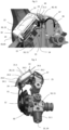
- Fig. 1 represents an embodiment of a fluid container 30, namely here a pressurized gas cylinder, such as an oxygen cylinder, equipped with a fluid distribution tap 10 with an electronic device 20 held by a protective cover 40 according to the invention,
- a pressurized gas cylinder such as an oxygen cylinder
- a fluid distribution tap 10 with an electronic device 20 held by a protective cover 40 according to the invention
- the pressurized gas cylinder (partially shown) conventionally comprises a cylindrical body 31 delimiting an internal volume receiving the pressurized fluid, typically a pressurized gas, such as medical oxygen, at a pressure (i.e. filled container) greater than 100 bar abs, typically at least 150 bar abs, or even more than 200 bar abs, for example a maximum pressure ranging from 130 to 300 bar abs.
- the container body 31 is generally made of metal or metal alloy, such as steel or an aluminum alloy, or composite materials.
- the container 30 carries a fluid distribution tap 10, preferably an RDI, i.e. a tap with an integrated pressure regulator, crossed by an internal fluid circuit in fluid communication with the internal volume of the container.
- RDI RDI
- an integrated pressure regulator a fluid distribution tap
- the fluid inlet orifice 13 is carried by the threaded fixing end 11.1 of the valve body 11, typically a threaded end 11.1 of conical shape.
- the fluid circuit 14 conveys the fluid, namely here gas, coming from the container 30 through the body of the gas distribution tap 11 to the fluid distribution nozzle 12 to which is usually fluidically connected a flexible gas line (not shown) used to convey the gas to another device (not shown) using the gas, that is to say a medical apparatus or device using the gas supplied by the tap 10, for example a breathing mask distributing gas to a patient at a flow rate prescribed by a doctor or the like corresponding to a treatment to be followed.
- a flexible gas line (not shown) used to convey the gas to another device (not shown) using the gas, that is to say a medical apparatus or device using the gas supplied by the tap 10, for example a breathing mask distributing gas to a patient at a flow rate prescribed by a doctor or the like corresponding to a treatment to be followed.
- the fluid stored in the container 30, i.e. in its internal volume, is typically a gas or gas mixture, for example of medical grade or gas medical, such as oxygen, air, NO/N 2 , Ar/O 2 , O 2 /N 2 O or He/O 2 mixture, or any other gas or gas mixture, preferably oxygen or an O 2 /N 2 O gas mixture.
- a gas or gas mixture for example of medical grade or gas medical, such as oxygen, air, NO/N 2 , Ar/O 2 , O 2 /N 2 O or He/O 2 mixture, or any other gas or gas mixture, preferably oxygen or an O 2 /N 2 O gas mixture.
- the gas distribution tap 10 comprises pressure measuring means making it possible to measure (at least) the pressure of the gas within the internal circuit 14 of the tap body 11.
- They typically comprise a pressure sensor having a pressure tap, i.e. a connection, fluidically connected to the internal circuit of the tap body 11.
- a combined pressure and temperature sensor is used to measure both the pressure and the temperature of the gas, within the internal gas circuit conveying the gas coming from the internal volume of the container 30.
- the pressure and preferably temperature measuring means are configured to provide the pressure and preferably temperature measurements (i.e. measurement signals or values) to microprocessor data processing means comprising one or more microprocessors implementing one or more algorithms, for example a main electronic card carrying one or more microprocessors implementing one or more calculation algorithms or the like, preferably a microcontroller.
- microprocessor data processing means comprising one or more microprocessors implementing one or more algorithms, for example a main electronic card carrying one or more microprocessors implementing one or more calculation algorithms or the like, preferably a microcontroller.
- these measurements i.e. signals or values
- data are sent to the microprocessor data processing means in order to be used there, i.e. processed electronically, in particular to determine, calculate or deduce a pressure or gas autonomy.
- a time counter may also be provided internal to the data processing means.
- the data processing means are arranged in the housing 21 of the electronic device 20, for example a digital pressure gauge, fixed to the body 11 of the fluid distribution tap 10, for example a rigid housing 21 made of polymer or metal.
- the housing 21 of the electronic device 20 here has a general rectangular parallelepiped shape.
- buttons 23 or selection keys that can be activated by digital pressure from the user to make choices, scroll through a menu(s), acknowledge an alarm or other.
- the electronic device also comprises display means 22, such as a digital display or screen, for example an LCD screen or the like, used to display various information, such as the volume or pressure of gas in the container 1 or the gas autonomy (in hours and minutes for example), which are in particular obtained by processing the pressure and/or temperature measurements by the data processing means, or to display an alarm message.
- display means 22 such as a digital display or screen, for example an LCD screen or the like, used to display various information, such as the volume or pressure of gas in the container 1 or the gas autonomy (in hours and minutes for example), which are in particular obtained by processing the pressure and/or temperature measurements by the data processing means, or to display an alarm message.
- the digital display 22 comprises a screen with a height of between approximately 29 and 37 mm and a width of, for example, between approximately 39 and 43 mm.
- the housing 21 comprises a tip 24, on its lower face, that is to say the one opposite the upper face carrying the screen 22.
- This tip 24 is housed in a tip housing 15 of the tap body 11, which is shaped and sized to receive the tip 24, as detailed below.
- the tip housing 15 has a blind bottom.
- the internal volume of the container 30 (in water equivalent) is a known value which can be stored by storage means, such as an EEPROM type computer memory, of the electronic device 20.
- the gas cylinders used to distribute medical oxygen i.e. medical grade
- the volume can be of the order of 2 L, 3.5 L, 4.6 L, 5 L, 7 L, 10 L, 11 L or 15 L.
- the storage means can also record other data, such as the time elapsed between successive moments, pressure and/or temperature measurements, etc., or other parameters, such as the position of the selector, the configuration of the bottle, the filling pressure, alerts, etc.
- the electronic device 20 for example a digital pressure gauge, which comprises the microprocessor data processing means, such as an electronic card, is housed in an opening 42, that is to say a window or the like, provided in the body 41 of the protective cover 40 which is arranged around the fluid distribution tap 10 and serving to protect it against shocks. or other possible deterioration, for example a rigid polymer and/or metal cover, as illustrated in Fig. 1
- the cover 40 is generally fixed to the neck of the container 30 or to the body 1 of the tap 10.
- the electronic device 20 is electrically powered by an electrical energy source 46, for example one or more batteries or cells arranged in a battery compartment 47, as illustrated in Fig. 3 and Fig. 4
- the electrical energy source is used to power the components requiring electrical current to operate, in particular the data processing means, the display screen 22, the memory, etc.
- the electrical energy source 46 is connected to the electronic device 20 by electrical connections, for example wires or the like.
- the data processing means are also configured to control audible alert means and/or visual alert means, preferably both, so as to trigger at least one audible alert and/or one visual alert, preferably both, in the event of detection of a malfunction, in particular a clamping, or of an excessively low quantity of gas or autonomy.
- a user-actuable flow rate selection device 50 such as a rotary handwheel, carried by the valve body 11 serves to select a desired gas flow rate to be delivered from the outlet nozzle 12, for example a rotary handwheel capable of rotating between several angular positions, offset from each other, which each correspond to a given flow rate value, for example selectable gas flow rate values between 0 L/min and 30 L/min, typically between 0 and 25 L/min.
- the selectable flow rate values may be: 0, 0.5, 1, 2, 3, 5, 8, 10, 12, 15, 20, 22 and 25 L/min, or any other value.
- the flow rate selection device 50 further cooperates with a flow rate adjustment device (not visible) arranged in the valve body 11 in order to adjust the flow rate to the desired gas flow rate value, for example the flow rate adjustment device may be a calibrated orifice disc arranged on the gas path in the valve body 11. Such an arrangement is known per se.
- the position of the flow selection device 50 for example the angular position of the rotary handwheel, can be determined using one (or more) position sensors 51 visible in Fig. 4 , which is electrically connected to the data processing means of the electronic device 20 to provide them with position information. This then allows the data processing means to know the value of the desired gas flow rate having been selected by the user.
- the flow outlet connection 12 is arranged centrally and coaxially with the flow selection rotary handwheel 50; however, they could also be separated from each other according to other possible embodiments (not shown).
- the flow outlet connection 12 carries an outlet orifice allowing gas distribution, that is to say it constitutes an outlet of the internal passage 14 of the valve body 11.
- gas outlet control means are also provided, typically a valve axially movable in the connector 12 and cooperating with a valve seat, sealing means, such as one or more O-rings, and an elastic means, such as a spring or the like, normally pushing the valve against the seat to ensure a gas seal when gas is not drawn off, i.e. distributed.
- the invention in order to be able to quickly and simply couple the electronic device 20 to the body 11 of the fluid distribution tap 10 without having to resort to machining the end piece 25 of the electronic device 20 or the end piece housing 15 of the tap body 11 where it is housed, and then to be able to disassemble them easily, in particular during maintenance or replacement operations, that is to say to overcome the aforementioned drawbacks, it is provided that at least a part of the peripheral wall 21.1 of the housing 21 of the electronic device 20 is shaped to cooperate with at least a part of the peripheral edge 43 of the opening 42, that is to say a window or the like, of the protective cover 40 to maintain the electronic device 20 secured to the valve body 11 and the protective cover 40, when the end piece 25 of the housing 21 is housed, that is to say positioned, in the end piece housing 15 of the valve body 11, as illustrated in Fig. 3 .
- the tip 25 of the housing 21 of the electronic device 20 therefore constitutes only a sort of centering stud which is inserted into the tip housing 15 of the valve body 11 to ensure correct positioning of the electronic device 20 on the body 11 of the fluid distribution valve 10.
- the tip 25 no longer participates in the actual fixing of the housing 21 to the valve body 11 since it is not retained by screwing, pin or other means, in the tip housing 15 of the valve body 11. It is simply inserted there, i.e. positioned there.
- the housing 21 of the electronic device 20 is held in place solely by the cover 40 which constrains it as detailed below.
- the peripheral wall 21.1 that is to say the external perimeter, of the housing 21 of the electronic device 20 and the peripheral edge 43, that is to say the periphery, of the opening 42 of the protective cover 40 are shaped to have complementary shapes making it possible to ensure the attachment of the electronic device 20 to the protective cover 40.
- the opening 42 of the cowling 40 that is to say a window or the like, has a circumference of substantially rectangular or square shape.
- the peripheral edge or periphery 43 of the opening 42 of the cover, or at least part of it which makes it possible to maintain the electronic device 20 in position on the tap body 11, and not a thread/tapping, a key or pin or the like as in the taps of the prior art.
- the electronic device 20 is secured by at least one peripheral groove 24 carried by the peripheral wall of the housing 21 of the electronic device 20 and by at least one shoulder 44 arranged at the peripheral edge 43 of the opening 42 of the protective cover 1 which cooperate together.
- peripheral groove(s) 24 could be arranged at the peripheral edge 43 of the opening 42 of the cover, and the shoulder(s) 44 on the periphery of the housing.
- the shoulder 44 is inserted into the peripheral groove 24 to ensure the securing, i.e. the fixing and maintenance, of the electronic device 20 to the protective cover 40.
- the groove 24 can be arranged mainly (continuous walls 24.1) on two opposite faces of the housing 21 when it is of rectangular parallelepiped shape (i.e. of approximately rectangular or square section), and extend slightly, i.e. over a short distance (i.e. discontinuous wall 24.2), on the other two faces, as illustrated in Fig. 4 .
- the housing 21 can have different shapes, for example being of circular section or other.
- the protective cover 40 is preferably formed of at least two half-shells, i.e. right half-shell and left half-shell, which couple to each other along a junction plane preferably passing through the opening 42, for example through the center of the opening 42, as illustrated in Fig. 3 , where only the left half-shell is put in place so that the housing 21 is positioned in a “half” opening 42.
- the end piece 25 of the housing 21 acts as a centering stud to ensure good positioning of the cover/electronic device assembly 40, 20 on the valve 10, when it is put in place by an operator, given that the end piece 25 of the housing 21 is positioned in the end piece housing 15 machined in the valve body 11, typically a housing or hole with a blind bottom.
- the cover 40 can then be firmly fixed, for example by screwing or the like, either to the body 11 of the valve 10, or to the neck of the gas container 30.
- the end piece 25 of the housing 21 has a substantially cylindrical general shape. It has a smooth peripheral wall, i.e., devoid of external threading or other means of attachment.
- the end piece housing 15 of the valve body 11 also has a substantially cylindrical general shape and a smooth internal wall, i.e., devoid of internal threading.
- their shapes are substantially complementary to one another, i.e., dimensioned to ensure stable, i.e., non-floating, retention of the end piece 25 of the housing 21 in the end piece housing 15 of the valve body 11.
- the tip housing 15 may have a height of the order of 6 to 8 mm and a diameter of the order of 7 to 9 mm
- the tip 25 of the housing 21 may have corresponding dimensions, i.e. a length of the order of 6 to 8 mm and a diameter of the order of 7 to 9 mm.
- other dimensions may be suitable.
- the end piece 25 of the housing 21 therefore acts as a centering stud whose function is to ensure good positioning of the cover 40/electronic device 20 assembly on the body 11 of the valve 10 and this, easily and without screwing or the like, while the electronic device 20 is held integral with the cover 40, and not with the body 11 of the tap, thanks to the cooperation between shoulder(s) 44 and groove(s) 24.
- the container according to the invention is particularly well suited for use in storing a medical gas chosen from oxygen, a gas mixture N 2 O/O 2 , NO/N 2 or He/O 2 , or medical air, advantageously medical grade oxygen.
Landscapes
- Engineering & Computer Science (AREA)
- Mechanical Engineering (AREA)
- General Engineering & Computer Science (AREA)
- Filling Or Discharging Of Gas Storage Vessels (AREA)
- Containers And Packaging Bodies Having A Special Means To Remove Contents (AREA)
Applications Claiming Priority (1)
| Application Number | Priority Date | Filing Date | Title |
|---|---|---|---|
| FR2311289A FR3154480B1 (fr) | 2023-10-19 | 2023-10-19 | Récipient de fluide muni d’un robinet de distribution à dispositif électronique maintenu par un capotage de protection |
Publications (1)
| Publication Number | Publication Date |
|---|---|
| EP4542103A1 true EP4542103A1 (de) | 2025-04-23 |
Family
ID=89767205
Family Applications (1)
| Application Number | Title | Priority Date | Filing Date |
|---|---|---|---|
| EP24201943.8A Pending EP4542103A1 (de) | 2023-10-19 | 2024-09-23 | Flüssigkeitsbehälter mit einem verteilerhahn mit einer elektronischen vorrichtung, die durch eine schutzabdeckung gehalten wird |
Country Status (6)
| Country | Link |
|---|---|
| US (1) | US20250129895A1 (de) |
| EP (1) | EP4542103A1 (de) |
| JP (1) | JP2025071026A (de) |
| AU (1) | AU2024227158A1 (de) |
| CA (1) | CA3247182A1 (de) |
| FR (1) | FR3154480B1 (de) |
Families Citing this family (1)
| Publication number | Priority date | Publication date | Assignee | Title |
|---|---|---|---|---|
| US20230297805A1 (en) * | 2022-03-17 | 2023-09-21 | Capital One Services, Llc | Finger-activated chip or contactless card |
Citations (15)
| Publication number | Priority date | Publication date | Assignee | Title |
|---|---|---|---|---|
| DE3809142A1 (de) | 1988-03-18 | 1989-10-05 | Hottinger Messtechnik Baldwin | Einrichtung zur anzeige eines messergebnisses |
| US6085598A (en) | 1999-02-22 | 2000-07-11 | Denso Corporation | Pressure sensor device having breakable mounting member |
| US20150048955A1 (en) | 2013-08-15 | 2015-02-19 | Western/The Scott Fetzer Company | Information gauge with analog backup |
| EP2918892A1 (de) | 2014-03-12 | 2015-09-16 | L'air Liquide, Societe Anonyme Pour L'etude Et L'exploitation Des Procedes Georges Claude | Schutzhaube für Gasflasche mit elektronischem Anzeigebildschirm in oberer Position |
| FR3018580A1 (fr) | 2014-03-12 | 2015-09-18 | Air Liquide | Bloc robinet pour recipient de gaz avec dispositif indicateur de pression ou d’autonomie en position haute |
| EP3002498A1 (de) | 2014-09-22 | 2016-04-06 | L'air Liquide, Societe Anonyme Pour L'etude Et L'exploitation Des Procedes Georges Claude | Gasbehälter mit absperrhahnblock, der mit einem berührungsbildschirm zur datenanzeige ausgestattet ist |
| EP3067665A1 (de) | 2011-06-02 | 2016-09-14 | Linde Aktiengesellschaft | Strömungsvorrichtung und überwachungssystem dafür |
| FR3052845A1 (fr) * | 2016-06-21 | 2017-12-22 | L'air Liquide Sa Pour L'etude Et L'exploitation Des Procedes Georges Claude | Capotage de protection de recipient de gaz a ouverture recouverte par paroi amovible |
| EP3377811A1 (de) | 2015-11-16 | 2018-09-26 | Luxembourg Patent Company S.A. | Zapfanordnung mit abdeckung und elektronischer zustandsanzeige |
| EP3421866A1 (de) | 2017-06-27 | 2019-01-02 | L'air Liquide Societe Anonyme Pour L'etude Et L'exploitation Des Procedes Georges Claude | Gas-absperrhahnblock mit elektronischer anzeigevorrichtung für gasbehälter mit einem elastischen verbindungselement |
| EP4027051A1 (de) | 2021-01-07 | 2022-07-13 | L'Air Liquide, société anonyme pour l'Étude et l'Exploitation des procédés Georges Claude | Gasbehälter, der mit einer elektronischen messvorrichtung ausgestattet ist |
| EP4056962A1 (de) | 2021-03-08 | 2022-09-14 | L'Air Liquide, société anonyme pour l'Étude et l'Exploitation des procédés Georges Claude | Druckbehälter für flüssigkeiten mit elektronischer vorrichtung zur berechnung und aktualisierten anzeige der flüssigkeitsmenge |
| EP4071399A1 (de) | 2021-04-07 | 2022-10-12 | L'Air Liquide, société anonyme pour l'Étude et l'Exploitation des procédés Georges Claude | Druckgasbehälter mit verteilventil und elektronischer vorrichtung, die die verwendung eines medizinischen beatmungsgeräts anzeigt |
| EP4071400A1 (de) | 2021-04-06 | 2022-10-12 | L'Air Liquide, société anonyme pour l'Étude et l'Exploitation des procédés Georges Claude | Druckbehälter für fluide mit elektronischer vorrichtung zur berechnung der fluidmenge |
| WO2023156960A1 (en) | 2022-02-17 | 2023-08-24 | Cavagna Group S.P.A. | Method for monitoring the passage of gas through a supply tube and valve configured for implementing it |
-
2023
- 2023-10-19 FR FR2311289A patent/FR3154480B1/fr active Active
-
2024
- 2024-09-23 EP EP24201943.8A patent/EP4542103A1/de active Pending
- 2024-09-30 CA CA3247182A patent/CA3247182A1/fr active Pending
- 2024-10-08 AU AU2024227158A patent/AU2024227158A1/en active Pending
- 2024-10-17 JP JP2024181813A patent/JP2025071026A/ja active Pending
- 2024-10-18 US US18/920,457 patent/US20250129895A1/en active Pending
Patent Citations (15)
| Publication number | Priority date | Publication date | Assignee | Title |
|---|---|---|---|---|
| DE3809142A1 (de) | 1988-03-18 | 1989-10-05 | Hottinger Messtechnik Baldwin | Einrichtung zur anzeige eines messergebnisses |
| US6085598A (en) | 1999-02-22 | 2000-07-11 | Denso Corporation | Pressure sensor device having breakable mounting member |
| EP3067665A1 (de) | 2011-06-02 | 2016-09-14 | Linde Aktiengesellschaft | Strömungsvorrichtung und überwachungssystem dafür |
| US20150048955A1 (en) | 2013-08-15 | 2015-02-19 | Western/The Scott Fetzer Company | Information gauge with analog backup |
| EP2918892A1 (de) | 2014-03-12 | 2015-09-16 | L'air Liquide, Societe Anonyme Pour L'etude Et L'exploitation Des Procedes Georges Claude | Schutzhaube für Gasflasche mit elektronischem Anzeigebildschirm in oberer Position |
| FR3018580A1 (fr) | 2014-03-12 | 2015-09-18 | Air Liquide | Bloc robinet pour recipient de gaz avec dispositif indicateur de pression ou d’autonomie en position haute |
| EP3002498A1 (de) | 2014-09-22 | 2016-04-06 | L'air Liquide, Societe Anonyme Pour L'etude Et L'exploitation Des Procedes Georges Claude | Gasbehälter mit absperrhahnblock, der mit einem berührungsbildschirm zur datenanzeige ausgestattet ist |
| EP3377811A1 (de) | 2015-11-16 | 2018-09-26 | Luxembourg Patent Company S.A. | Zapfanordnung mit abdeckung und elektronischer zustandsanzeige |
| FR3052845A1 (fr) * | 2016-06-21 | 2017-12-22 | L'air Liquide Sa Pour L'etude Et L'exploitation Des Procedes Georges Claude | Capotage de protection de recipient de gaz a ouverture recouverte par paroi amovible |
| EP3421866A1 (de) | 2017-06-27 | 2019-01-02 | L'air Liquide Societe Anonyme Pour L'etude Et L'exploitation Des Procedes Georges Claude | Gas-absperrhahnblock mit elektronischer anzeigevorrichtung für gasbehälter mit einem elastischen verbindungselement |
| EP4027051A1 (de) | 2021-01-07 | 2022-07-13 | L'Air Liquide, société anonyme pour l'Étude et l'Exploitation des procédés Georges Claude | Gasbehälter, der mit einer elektronischen messvorrichtung ausgestattet ist |
| EP4056962A1 (de) | 2021-03-08 | 2022-09-14 | L'Air Liquide, société anonyme pour l'Étude et l'Exploitation des procédés Georges Claude | Druckbehälter für flüssigkeiten mit elektronischer vorrichtung zur berechnung und aktualisierten anzeige der flüssigkeitsmenge |
| EP4071400A1 (de) | 2021-04-06 | 2022-10-12 | L'Air Liquide, société anonyme pour l'Étude et l'Exploitation des procédés Georges Claude | Druckbehälter für fluide mit elektronischer vorrichtung zur berechnung der fluidmenge |
| EP4071399A1 (de) | 2021-04-07 | 2022-10-12 | L'Air Liquide, société anonyme pour l'Étude et l'Exploitation des procédés Georges Claude | Druckgasbehälter mit verteilventil und elektronischer vorrichtung, die die verwendung eines medizinischen beatmungsgeräts anzeigt |
| WO2023156960A1 (en) | 2022-02-17 | 2023-08-24 | Cavagna Group S.P.A. | Method for monitoring the passage of gas through a supply tube and valve configured for implementing it |
Also Published As
| Publication number | Publication date |
|---|---|
| US20250129895A1 (en) | 2025-04-24 |
| AU2024227158A1 (en) | 2025-05-08 |
| JP2025071026A (ja) | 2025-05-02 |
| CA3247182A1 (fr) | 2025-06-03 |
| FR3154480A1 (fr) | 2025-04-25 |
| FR3154480B1 (fr) | 2025-12-26 |
Similar Documents
| Publication | Publication Date | Title |
|---|---|---|
| EP3117136B1 (de) | Ventileinheit für gasbehälter mit druckanzeigender oder betriebszeitanzeigender vorrichtung nahe der oberseite | |
| EP3002498B1 (de) | Gasbehälter mit absperrhahnblock, der mit einem berührungsbildschirm zur datenanzeige ausgestattet ist | |
| WO2005093377A2 (fr) | Systeme de traitement integre et compact pour mesurer l'autonomie en gaz d'un reservoir | |
| EP4542103A1 (de) | Flüssigkeitsbehälter mit einem verteilerhahn mit einer elektronischen vorrichtung, die durch eine schutzabdeckung gehalten wird | |
| EP3851733B1 (de) | Flüssigkeitsbehälter, der eine elektronische messanzeige mit verbessertem digitalen display umfasst | |
| CA3024810A1 (fr) | Recipient de fluide sous pression a jauge de contrainte et moyens de communication a distance | |
| EP4071400B1 (de) | Druckbehälter für fluide mit elektronischer vorrichtung zur berechnung der fluidmenge | |
| EP4056962B1 (de) | Druckbehälter für gase mit elektronischer vorrichtung zur berechnung und aktualisierten anzeige der gasmenge | |
| EP4027051B1 (de) | Gasbehälter, der mit einer elektronischen messvorrichtung ausgestattet ist | |
| EP3913276B1 (de) | Druckgasbehälter, der mit einer elektronischen vorrichtung mit mitteln zur bestätigung von alarmen ausgestattet ist | |
| FR3112192A1 (fr) | Récipient de fluide sous pression avec dispositif électronique embarquant un capteur de pression et température | |
| EP3391926B1 (de) | Gasauslassanschluss, der mit einem integrierten durchflussmesser verbunden ist | |
| EP4071399B1 (de) | Druckgasbehälter mit verteilventil und elektronischer vorrichtung, die die verwendung eines medizinischen beatmungsgeräts anzeigt | |
| EP4403818B1 (de) | Flüssigkeitsbehälter mit einem verteilerhahn mit elektronischer vorrichtung und unabhängigem drucksensor | |
| FR3133425A3 (fr) | Récipient de fluide sous pression équipé d’un dispositif électronique de calcul et d’affichage d’autonomie | |
| FR3154481A1 (fr) | Récipient de fluide sous pression avec dispositif électronique et détection d’un dysfonctionnement du capteur de température | |
| EP3943802B1 (de) | Fluidbehälter unter druck mit elektronischer vorrichtung, die eine korrektur der temperatur- und druckmessungen ausführt | |
| FR3106186A1 (fr) | Récipient de gaz équipé d’un dispositif de mesure électronique portant une IHM | |
| FR3061547B1 (fr) | Appareil pour determiner le debit massique ou l’autonomie en gaz d’une bouteille de gaz, notamment d’oxygene medical | |
| FR3113106A1 (fr) | Récipient de fluide sous pression avec dispositif électronique à système d'endormissement et de réveil des moyens de communication avec l’extérieur | |
| FR2950041A1 (fr) | Dispositif de remplissage d'un recipient et procede de remplissage associe | |
| FR3082914A1 (fr) | Robinet pour recipient de gaz comprenant un manometre protege par une piece-berceau | |
| CH695102A5 (fr) | Procédé et dispositif de remplissage et de prélèvement de liquides. |
Legal Events
| Date | Code | Title | Description |
|---|---|---|---|
| PUAI | Public reference made under article 153(3) epc to a published international application that has entered the european phase |
Free format text: ORIGINAL CODE: 0009012 |
|
| STAA | Information on the status of an ep patent application or granted ep patent |
Free format text: STATUS: THE APPLICATION HAS BEEN PUBLISHED |
|
| AK | Designated contracting states |
Kind code of ref document: A1 Designated state(s): AL AT BE BG CH CY CZ DE DK EE ES FI FR GB GR HR HU IE IS IT LI LT LU LV MC ME MK MT NL NO PL PT RO RS SE SI SK SM TR |
|
| STAA | Information on the status of an ep patent application or granted ep patent |
Free format text: STATUS: REQUEST FOR EXAMINATION WAS MADE |
|
| 17P | Request for examination filed |
Effective date: 20251023 |