EP3854280A1 - Machine pour aspirer et broyer les feuilles - Google Patents
Machine pour aspirer et broyer les feuilles Download PDFInfo
- Publication number
- EP3854280A1 EP3854280A1 EP20153599.4A EP20153599A EP3854280A1 EP 3854280 A1 EP3854280 A1 EP 3854280A1 EP 20153599 A EP20153599 A EP 20153599A EP 3854280 A1 EP3854280 A1 EP 3854280A1
- Authority
- EP
- European Patent Office
- Prior art keywords
- machine
- rotor
- sucking
- rotors
- leaves according
- Prior art date
- Legal status (The legal status is an assumption and is not a legal conclusion. Google has not performed a legal analysis and makes no representation as to the accuracy of the status listed.)
- Withdrawn
Links
- 230000007423 decrease Effects 0.000 claims description 5
- 230000001154 acute effect Effects 0.000 claims description 3
- 239000000463 material Substances 0.000 description 3
- 241000531891 Alburnus alburnus Species 0.000 description 1
- 241000894006 Bacteria Species 0.000 description 1
- 241000446313 Lamella Species 0.000 description 1
- 230000015556 catabolic process Effects 0.000 description 1
- 238000002485 combustion reaction Methods 0.000 description 1
- 238000009264 composting Methods 0.000 description 1
- 238000006731 degradation reaction Methods 0.000 description 1
- 230000000694 effects Effects 0.000 description 1
- 239000004744 fabric Substances 0.000 description 1
- 239000002245 particle Substances 0.000 description 1
- 238000009419 refurbishment Methods 0.000 description 1
Images

Classifications
-
- A—HUMAN NECESSITIES
- A01—AGRICULTURE; FORESTRY; ANIMAL HUSBANDRY; HUNTING; TRAPPING; FISHING
- A01G—HORTICULTURE; CULTIVATION OF VEGETABLES, FLOWERS, RICE, FRUIT, VINES, HOPS OR SEAWEED; FORESTRY; WATERING
- A01G20/00—Cultivation of turf, lawn or the like; Apparatus or methods therefor
- A01G20/40—Apparatus for cleaning the lawn or grass surface
- A01G20/43—Apparatus for cleaning the lawn or grass surface for sweeping, collecting or disintegrating lawn debris
- A01G20/47—Vacuum or blower devices
-
- E—FIXED CONSTRUCTIONS
- E01—CONSTRUCTION OF ROADS, RAILWAYS, OR BRIDGES
- E01H—STREET CLEANING; CLEANING OF PERMANENT WAYS; CLEANING BEACHES; DISPERSING OR PREVENTING FOG IN GENERAL CLEANING STREET OR RAILWAY FURNITURE OR TUNNEL WALLS
- E01H1/00—Removing undesirable matter from roads or like surfaces, with or without moistening of the surface
- E01H1/08—Pneumatically dislodging or taking-up undesirable matter or small objects; Drying by heat only or by streams of gas; Cleaning by projecting abrasive particles
- E01H1/0827—Dislodging by suction; Mechanical dislodging-cleaning apparatus with independent or dependent exhaust, e.g. dislodging-sweeping machines with independent suction nozzles ; Mechanical loosening devices working under vacuum
- E01H1/0836—Apparatus dislodging all of the dirt by suction ; Suction nozzles
Definitions
- the invention relates to a machine, in particular a mobile machine, for sucking up and crushing leaves, with a channel-shaped housing having an inlet and an outlet, in which a rotor with several rotor blades is provided, which is arranged on a rotatably mounted shaft and driven by a motor the rotor blades for sucking in the leaves through the inlet are each inclined at least in a partial area and, viewed in the direction of rotation, each have a cutting edge on their front side.
- Such machines are known from practice, which are usually used to dispose of the leaves that arise especially in autumn.
- the leaves are not only sucked up, but also shredded to a certain extent at the same time.
- the disadvantage here is that the comminution is not strong enough, so that the space requirement of the comminuted material is still quite high.
- the not so strong crushing also slows down the biological degradation, since the bacteria can penetrate more easily in the case of more strongly crushed material and thus the composting can take place more quickly.
- the object of the invention is to avoid the aforementioned disadvantages and to provide a machine for sucking up and chopping up leaves, with which an improved and stronger chopping is possible.
- This object is achieved in a generic machine for sucking up and chopping up leaves in that at least one further rotor, also arranged on a rotatably mounted shaft and driven by a motor, is provided in the housing with several rotor blades, the rotor blades for sucking in the Laubes are inclined through the inlet at least in a partial area and, viewed in the direction of rotation, each have a cutting edge on their front side, the shafts of the rotors being provided coaxially and the rotors being arranged one behind the other as seen in the intake direction, and at least two one behind the other seen in the intake direction lying rotors are driven to rotate in opposite directions.
- the "pitch" of the rotor blades is chosen so that they suck in the leaves etc. in their normal direction of rotation.
- One rotor is usually provided for each shaft, since a different shaft is required for a different direction of rotation. However, if two rotors arranged directly one behind the other rotate in the same direction, they can be arranged on the same shaft.
- the rotor blades can preferably be designed as crescent-shaped lamellae extending outwards, in particular as convex crescent-shaped lamellae extending outwardly. This has the advantage that stubborn goods are less likely to "get stuck” than would be the case with a concave crescent-shaped lamella which would be shaped like a scythe.
- the outer edges of the rotor blades can be equipped with spikes, so that more resistant material is also torn or separated or cut off as a result.
- the angle at which the rotor blades are set can also decrease radially outward from the shaft, so that the conveying speed is standardized, taking into account the circumferential speeds that increase with increasing distance from the shaft.
- the width of the rotor blades can decrease radially outward in at least a partial area of the extension from the shaft and / or with at least one rotor the width of the rotor blades can increase radially outward in at least a partial area of the extension from the shaft.
- the rotor blades can taper or widen in the radial direction or any combination of sequences thereof.
- the rotor blades can have a diamond-shaped or almond-shaped configuration in plan view.
- a tapered shape is also possible, in which the rotor blades initially taper in the radial direction or then widen again.
- At least one cutting edge can be provided by a cutting bar attached to the front edge of the rotor, as seen in the direction of rotation of the rotor be formed, so that an exchange or refurbishment of the cutting bar in the event of wear or dulling is possible easily and without dismantling the rotor.
- an even number of rotors can be provided with at least four rotors, of which one half of the rotors rotates in a first direction and the other half of the rotors rotates in the opposite direction.
- an odd number of rotors can also be provided.
- all rotors can be driven with a fixed speed ratio, in particular with a corresponding speed. This simplifies the technical structure and all rotors can be driven in a simple manner with one motor.
- At least two rotors in particular all rotors, can be driven by a single motor, which rotates at least one rotor in a first direction via a corresponding reversing gear and rotates at least one other rotor in the opposite direction, preferably a first part or one half of the Rotates rotors in a first direction and rotates a second part or half of the rotors in the opposite direction.
- the coaxially arranged shafts of the rotors can be driven by a single motor via a corresponding gear.
- the housing can be cylindrical, the housing being oriented vertically or at an acute angle to the vertical, and wherein the inlet is provided in the lower circular cutting surface, preferably encompasses the area of the entire lower circular cutting surface, and the outlet in the upper area of the Housing is provided and is preferably designed as a radial or tangential outlet.
- the outlet can be provided to the rear in the direction of travel and preferably be arranged within the width of the machine.
- the machine can be provided on the underside with at least two wheels or rollers, preferably three or four wheels or rollers, and in particular have a motor for driving at least some of the wheels or rollers.
- a cyclone separator and / or a removable collecting container can be connected to the outlet, which is preferably provided with at least partially air-permeable walls and / or is designed as a pull-out leaf box.
- the collecting container can be designed analogously to a lawn mower collecting basket and in particular have a fabric with a small mesh size of approx. 0.5 mm to approx. 2 mm.
- the cyclone separator can be arranged above the collecting basket at an acute angle to the collecting basket, so that the separated particles can fall directly into the collecting basket.
- the collecting container can also be suspended similar to a lawn mower, which enables a simple and technically established and easily detachable attachment.
- the distance between the lowest rotor and the ground on which the machine is located can be changed, whereby the distance between the lowermost rotor and the ground on which the machine is located, preferably the position of the wheels or rollers relative to the housing, can be adjusted .
- an internal adjustment can also be provided with which at least the height of the lowest rotor, and thus its distance from the ground, can be changed and set to a suitable value.
- the channel-shaped housing with the rotors arranged therein can be arranged one behind the other in the area between two as seen in the suction direction arranged rotors have at least one bend, in particular the axis of rotation of the shaft on which the rotor is arranged before the bend and the axis of rotation of the shaft on which the rotor is arranged after the bend are aligned parallel to one another.
- the "channel" in which the rotors are arranged does not necessarily have to be straight, which opens up expanded design options for the machine.
- the bend can either be relatively sharp-edged, but it can also be designed as a bend or even only a slight curvature.
- the machine can be designed for lawn mowing and provided with three or four wheels on the underside, the cutting edges of the rotor blades of the lowest rotor being in a plane of rotation and the distance of the lowest rotor to the ground on which the machine is located , is designed so small that the cutting edges are in contact with the lawn to be mowed when the machine is used.
- the bottom rotor can be designed differently from the other rotors.
- the direction of rotation of the lowermost rotor can also be arbitrary in relation to the other rotors.
- the distance between the lowest rotor and the ground on which the machine is located can be adjusted to set the desired cutting height.
- the distance and the resulting cutting height can be adjustable, for example, to 3 cm to 10 cm, preferably to 4 cm to 6 cm and preferably to approx. 5 cm.
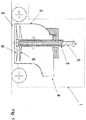
- Fig. 1 shows a machine 1 for sucking up and crushing leaves not shown in the drawing.
- the machine 1 has a channel-shaped housing 2 with an inlet 3 and an outlet 4.
- two rotatably mounted shafts 5 are arranged, which are driven by a motor not shown in the drawing.
- a rotor 6 with a plurality of rotor blades 7 is arranged on each shaft 5.
- the shafts 5 are designed as an arrangement of several shafts 5 provided coaxially.
- a rotor 6 is usually provided for each shaft 5, as shown in the exemplary embodiment shown, since a different shaft 5 is also required for a different direction of rotation. If two rotors 6 arranged directly one behind the other are rotating in the same way, they can, however, be arranged on the same shaft 5.
- the rotor blades 7 for sucking in the leaves through the inlet 3 are each inclined in a partial area adjoining the shaft 5 and each have a cutting edge 8 on their front side when viewed in the direction of rotation.
- the angle at which the rotor blades 7 are employed is designed to decrease radially outward from the shaft 6.
- the rotor blade 7 is formed by a strip of constant width, which is increasingly twisted radially towards the shaft 5 with respect to the plane of rotation.
Landscapes
- Engineering & Computer Science (AREA)
- Architecture (AREA)
- Civil Engineering (AREA)
- Structural Engineering (AREA)
- Life Sciences & Earth Sciences (AREA)
- Environmental Sciences (AREA)
- Harvester Elements (AREA)
Priority Applications (1)
| Application Number | Priority Date | Filing Date | Title |
|---|---|---|---|
| EP20153599.4A EP3854280A1 (fr) | 2020-01-24 | 2020-01-24 | Machine pour aspirer et broyer les feuilles |
Applications Claiming Priority (1)
| Application Number | Priority Date | Filing Date | Title |
|---|---|---|---|
| EP20153599.4A EP3854280A1 (fr) | 2020-01-24 | 2020-01-24 | Machine pour aspirer et broyer les feuilles |
Publications (1)
| Publication Number | Publication Date |
|---|---|
| EP3854280A1 true EP3854280A1 (fr) | 2021-07-28 |
Family
ID=69191967
Family Applications (1)
| Application Number | Title | Priority Date | Filing Date |
|---|---|---|---|
| EP20153599.4A Withdrawn EP3854280A1 (fr) | 2020-01-24 | 2020-01-24 | Machine pour aspirer et broyer les feuilles |
Country Status (1)
| Country | Link |
|---|---|
| EP (1) | EP3854280A1 (fr) |
Citations (2)
| Publication number | Priority date | Publication date | Assignee | Title |
|---|---|---|---|---|
| WO2016179473A1 (fr) * | 2015-05-07 | 2016-11-10 | Black & Decker Inc. | Appareil d'aspiration et soufflante à ventilateur axial |
| EP3492750A1 (fr) * | 2017-11-30 | 2019-06-05 | TTI (Macao Commercial Offshore) Limited | Ventilateur/appareil de paillage |
-
2020
- 2020-01-24 EP EP20153599.4A patent/EP3854280A1/fr not_active Withdrawn
Patent Citations (2)
| Publication number | Priority date | Publication date | Assignee | Title |
|---|---|---|---|---|
| WO2016179473A1 (fr) * | 2015-05-07 | 2016-11-10 | Black & Decker Inc. | Appareil d'aspiration et soufflante à ventilateur axial |
| EP3492750A1 (fr) * | 2017-11-30 | 2019-06-05 | TTI (Macao Commercial Offshore) Limited | Ventilateur/appareil de paillage |
Similar Documents
| Publication | Publication Date | Title |
|---|---|---|
| DE69602900T2 (de) | Verbesserungen an Rasenmäher | |
| EP0795266A2 (fr) | Souffleur-aspirateur, en particulier aspirateur hacheur, pour collecter et broyer du gazon et des produits similaires | |
| DE2451186A1 (de) | Zuckerrohrerntemaschine | |
| DE2912466A1 (de) | Schnittgrasfoerdereinrichtung an sichelrasenmaehern | |
| DE112011105538T5 (de) | Schnittmesser | |
| WO2016030236A1 (fr) | Dispositif de mesure pour un appareil de cuisine et appareil de cuisine équipé d'un dispositif de mesure | |
| DE10247281B3 (de) | Zerkleinerungsmaschine für Material beliebiger Art, z.B. Abfall oder Holz | |
| DE202020103842U1 (de) | Laubsauger | |
| DE2147375C2 (de) | Graskonditionierungsmaschine | |
| EP0598306B1 (fr) | Déchiqueteur en particulier pour déchets ménagers et débris de jardin | |
| DE2624983A1 (de) | Rasenmaeher | |
| EP3696385B1 (fr) | Dispositif de refroidissement pour une machine de travail agricole | |
| EP3854280A1 (fr) | Machine pour aspirer et broyer les feuilles | |
| EP1967061B1 (fr) | Hache-paille et moissonneuse équipée de celle-ci | |
| DE4202865A1 (de) | Rasenmaeher | |
| EP3092885A1 (fr) | Faucheuse | |
| EP1181858A1 (fr) | Système de coupe et de déchiquetage pour tondeuse à gazon | |
| DE4311343C2 (de) | Mähmaschine | |
| DE4427700C2 (de) | Vorrichtung zum Häckseln von Gartenabfällen | |
| DE2639519C3 (de) | Saugmähgerät | |
| DE10234814A1 (de) | Schneidvorrichtung für Pflanzen | |
| EP4379142B1 (fr) | Aspirateur de feuilles avec une entrée pour aspirer les feuilles et une sortie pour décharger les feuilles | |
| DE10319032B3 (de) | Mäh- und Mulchmesser sowie dessen Anordnung in Sichelmähern | |
| DE20319363U1 (de) | Mulchmäher | |
| EP1782680B1 (fr) | Dispositif pour le broyage de produits végétaux dans la forme de masse verte ou de jeunes buissons |
Legal Events
| Date | Code | Title | Description |
|---|---|---|---|
| PUAI | Public reference made under article 153(3) epc to a published international application that has entered the european phase |
Free format text: ORIGINAL CODE: 0009012 |
|
| STAA | Information on the status of an ep patent application or granted ep patent |
Free format text: STATUS: THE APPLICATION HAS BEEN PUBLISHED |
|
| AK | Designated contracting states |
Kind code of ref document: A1 Designated state(s): AL AT BE BG CH CY CZ DE DK EE ES FI FR GB GR HR HU IE IS IT LI LT LU LV MC MK MT NL NO PL PT RO RS SE SI SK SM TR |
|
| STAA | Information on the status of an ep patent application or granted ep patent |
Free format text: STATUS: THE APPLICATION IS DEEMED TO BE WITHDRAWN |
|
| 18D | Application deemed to be withdrawn |
Effective date: 20220129 |