EP3854652B1 - Eisenbahntriebwagen mit einer vorrichtung zur befestigung von technischen ausrüstungsgegenständen - Google Patents
Eisenbahntriebwagen mit einer vorrichtung zur befestigung von technischen ausrüstungsgegenständen Download PDFInfo
- Publication number
- EP3854652B1 EP3854652B1 EP21152877.3A EP21152877A EP3854652B1 EP 3854652 B1 EP3854652 B1 EP 3854652B1 EP 21152877 A EP21152877 A EP 21152877A EP 3854652 B1 EP3854652 B1 EP 3854652B1
- Authority
- EP
- European Patent Office
- Prior art keywords
- rails
- power car
- longitudinal direction
- joining
- gutter
- Prior art date
- Legal status (The legal status is an assumption and is not a legal conclusion. Google has not performed a legal analysis and makes no representation as to the accuracy of the status listed.)
- Active
Links
Images


Classifications
-
- B—PERFORMING OPERATIONS; TRANSPORTING
- B61—RAILWAYS
- B61D—BODY DETAILS OR KINDS OF RAILWAY VEHICLES
- B61D37/00—Other furniture or furnishings
-
- B—PERFORMING OPERATIONS; TRANSPORTING
- B61—RAILWAYS
- B61C—LOCOMOTIVES; MOTOR RAILCARS
- B61C17/00—Arrangement or disposition of parts; Details or accessories not otherwise provided for; Use of control gear and control systems
-
- B—PERFORMING OPERATIONS; TRANSPORTING
- B61—RAILWAYS
- B61C—LOCOMOTIVES; MOTOR RAILCARS
- B61C3/00—Electric locomotives or railcars
-
- A—HUMAN NECESSITIES
- A47—FURNITURE; DOMESTIC ARTICLES OR APPLIANCES; COFFEE MILLS; SPICE MILLS; SUCTION CLEANERS IN GENERAL
- A47B—TABLES; DESKS; OFFICE FURNITURE; CABINETS; DRAWERS; GENERAL DETAILS OF FURNITURE
- A47B96/00—Details of cabinets, racks or shelf units not covered by a single one of groups A47B43/00 - A47B95/00; General details of furniture
- A47B96/02—Shelves
- A47B96/024—Shelves characterised by support bracket location means, e.g. fixing means between support bracket and shelf
-
- A—HUMAN NECESSITIES
- A47—FURNITURE; DOMESTIC ARTICLES OR APPLIANCES; COFFEE MILLS; SPICE MILLS; SUCTION CLEANERS IN GENERAL
- A47B—TABLES; DESKS; OFFICE FURNITURE; CABINETS; DRAWERS; GENERAL DETAILS OF FURNITURE
- A47B96/00—Details of cabinets, racks or shelf units not covered by a single one of groups A47B43/00 - A47B95/00; General details of furniture
- A47B96/06—Brackets or similar supporting means for cabinets, racks or shelves
-
- B—PERFORMING OPERATIONS; TRANSPORTING
- B61—RAILWAYS
- B61C—LOCOMOTIVES; MOTOR RAILCARS
- B61C17/00—Arrangement or disposition of parts; Details or accessories not otherwise provided for; Use of control gear and control systems
- B61C17/04—Arrangement or disposition of driving cabins, footplates or engine rooms; Ventilation thereof
-
- B—PERFORMING OPERATIONS; TRANSPORTING
- B61—RAILWAYS
- B61D—BODY DETAILS OR KINDS OF RAILWAY VEHICLES
- B61D15/00—Other railway vehicles, e.g. scaffold cars; Adaptations of vehicles for use on railways
-
- B—PERFORMING OPERATIONS; TRANSPORTING
- B61—RAILWAYS
- B61D—BODY DETAILS OR KINDS OF RAILWAY VEHICLES
- B61D17/00—Construction details of vehicle bodies
- B61D17/04—Construction details of vehicle bodies with bodies of metal; with composite, e.g. metal and wood body structures
- B61D17/10—Floors
-
- B—PERFORMING OPERATIONS; TRANSPORTING
- B61—RAILWAYS
- B61D—BODY DETAILS OR KINDS OF RAILWAY VEHICLES
- B61D49/00—Other details
-
- A—HUMAN NECESSITIES
- A47—FURNITURE; DOMESTIC ARTICLES OR APPLIANCES; COFFEE MILLS; SPICE MILLS; SUCTION CLEANERS IN GENERAL
- A47B—TABLES; DESKS; OFFICE FURNITURE; CABINETS; DRAWERS; GENERAL DETAILS OF FURNITURE
- A47B2230/00—Furniture jointing; Furniture with such jointing
- A47B2230/0003—Adjustable furniture jointing
- A47B2230/0018—Screws or bolts sliding in sectional grooves
Definitions
- the present invention relates to a railway engine, in particular for the transport of passengers, of the type comprising: a body extending in a longitudinal direction, the body comprising a floor and two side walls defining a technical room; and cabinets received in the technical room, said cabinets being intended to receive electrical and/or electronic and/or pneumatic equipment.
- Such a railway engine is for example described in the document EP3453584 in the name of the Applicant and in the document US 2015/166082 .
- Such railway engines generally include longitudinal structures fixed to the floor of the technical room, commonly called body sills. These structures are intended to support electrical cabinets and to provide routing for cables and pneumatic pipes.
- the aim of the present invention is to propose a standardized device capable of replacing body sills, making it possible to use the same structure at several locations on the power car and/or in several different types of power cars.
- the subject of the invention is a railway power car of the aforementioned type, comprising at least two rails arranged on the floor, each of said rails extending in the longitudinal direction preferably with a substantially constant section, an upper part of each said rails forming a first means of assembly with a cabinet.
- Each cabinet comprises at least one leg, said or each of said legs comprising a second assembly means capable of cooperating with the first assembly means of one of said rails, each first assembly means and each second assembly means being configured so that each cabinet can be fixed to said corresponding rail in an infinite number of positions along said rail; two of the rails being arranged on either side of a central corridor extending in the longitudinal direction in the technical room , the cabinets being arranged along the side walls on either side of said central corridor; the railway engine further comprising a gutter disposed on the floor in the central corridor, said gutter extending in the longitudinal direction, said gutter being intended to receive cables and/or equipment pipes from the power car; the railway power car further comprising plates assembled above the gutter and distributed along the longitudinal direction.
- the invention further relates to a railway vehicle comprising a railway engine as described above.
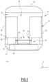
- FIG. 1 represents a railway engine 10, or railway locomotive, according to one embodiment of the invention.
- the power unit 10 is intended to be assembled with railway vehicles such as passenger transport wagons, to form a train.
- the engine 10 is preferably a high-speed train engine or a locomotive pulling freight wagons or passenger cars.
- the power car 10 comprises a body 12, as well as at least two bogies (not shown) and at least one traction motor 14, arranged under said body 12.
- the traction motor 14 is intended to set the wheels of the bogies in motion.
- the motor 10 further comprises a plurality of technical cabinets 15.
- the body 12 includes a roof 16 and a floor 18, which vertically delimit said body.
- the bogies and the traction motor 14 are arranged under the floor 18.
- the body 12 also includes side walls 20.
- the box 12 has an elongated shape. We consider an orthonormal base (X, Y, Z), the direction Z representing the vertical.
- the body 12 extends mainly in the direction X, corresponding to a usual direction of movement of the motor vehicle 10.
- the box 12 includes a technical compartment 22, shown in section on the figure 1 .
- the technical compartment 22 comprises in particular: a first removable assembly device 24; and a cable tray 26.
- the first device 24 is intended for removable assembly with the technical cabinets 15.
- the first device 24 comprises two rails 28, fixed to the floor 18 and extending along X.
- the two rails 28, substantially identical, will be described more precisely below After.
- a space located between the two rails 28 along Y defines a central corridor 30 in the technical compartment 22.
- said central corridor 30 has a width along Y of between 500 mm and 750 mm, preferably equal to approximately 750 mm. This width is determined to allow comfortable passage for an operator, without significantly limiting the volume available for the equipment of the motor vehicle 10.
- the cable tray 26 extends along X and is fixed to the floor 18 in the central corridor 30, between the two rails 28.
- the cable tray 26 will be described more precisely below.
- the technical cabinets 15 are installed in the technical compartment 22 near the side walls 20, on either side of the central corridor 30.
- Each technical cabinet 15 comprises a box 32 and a second device 34 for removable assembly with the box 12.
- the box 32 has a substantially parallelepiped shape and is intended to receive electrical and/or electronic equipment from the motor 10. Alternatively, the box 32 is intended to receive pneumatic equipment, such as pipes.
- FIG. 2 shows a detailed view of a rail 28 and the second removable assembly device 34 of a technical cabinet 15, assembled together.
- Rail 28 also visible in perspective on the Figure 3 , has a substantially constant section along X.
- the rail 28 comprises a lower element 40 and an upper element 42.
- Each of said lower 40 and upper 42 elements has a constant section, so that it can be manufactured in a single piece by folding and/or or extrusion along X.
- the lower 40 and upper 42 elements are for example made of steel and/or stainless steel.
- the lower element 40 intended to rest on the floor 18, has a U-shaped section, the branches 43 of the U being directed upwards.
- the upper element 42 intended to rest on the ends of the branches of the U, is configured for removable assembly with the second assembly device 34.
- the upper element 42 comprises an upper wall 44 substantially horizontal, in which a longitudinal slot 46 is provided.
- a longitudinal slot 46 is provided.
- at least one first end 48 along X of said slot is an open end.
- the upper element 42 comprises a substantially tubular groove 50, onto which the longitudinal slot 46 opens.
- the upper element further comprises two substantially flat fins 52, arranged on either side of the groove 50, each fin resting on a branch 43 of the U of the lower element 40.
- the lower element 40 is produced by folding a sheet and the upper element 42 is produced by extrusion, the two elements then being welded to each other.
- the second assembly device 34 of the technical cabinet 15 comprises at least one foot 56, extending substantially vertically under the box 32.
- the second assembly device 34 comprises at least two substantially identical feet 56, aligned along a first edge 58 of the box 32.
- the first edge 58 is oriented along X and adjacent to the central corridor 30.
- the foot 56 comprises a lower end in the form of a substantially horizontal plate 60, capable of resting on the upper wall 44 of the upper element 42 of the rail 28.
- the plate 60 is equipped with a means 62 for fixing to said wall upper 44.
- the fixing means 62 is a removable bolt-type clamping device, comprising: a clamping rod 64, which passes through the longitudinal slot 46 and the plate 60 of the foot 56; and a nut 66 assembled to the clamping rod 64 above said plate 60.
- the fixing means 62 In a loose configuration of the nut 66, the fixing means 62 is able to slide along X in the longitudinal slot 46. In a tight configuration of said nut, the fixing means 62 fixes the foot 56 in a precise position along rail 28.
- the trunk 32 comprises a second edge 68, opposite the first edge 58 and adjacent to a side wall 20 of the body 12.
- the second edge 68 of the trunk 32 rests on a horizontal shoulder 70 extending along X along said side wall.
- the first assembly device 24 further comprises a third and a fourth rails 28 in place of said shoulders 70 and the second assembly device 34 comprises additional feet 56 at the level of the second edge 68 of the trunk 32, for an assembly similar to that described above.
- the cable tray 26 comprises a gutter 72 and upper slabs 74.
- the gutter 72 extending along motor 10.
- the gutter 72 notably comprises a bottom 76, as well as substantially vertical amounts 78.
- the gutter 72 has a substantially constant section, so that it can be manufactured in one piece by a folding step.
- the bottom 76 and/or the uprights 78 have perforations (not shown) arranged regularly along X and allowing assembly with other elements.
- the upper slabs 74 are arranged on the gutter 72. Preferably, said upper slabs 74 are distributed regularly along said gutter, so as to form a support allowing an operator to cross the central corridor 30 above the cables and/or or pipes received in the gutter.
- the upper slabs 74 are fixed to the uprights 78 of the gutter by removable fixings 80 of screw or rivet type, cooperating in particular with perforations made in said uprights.
- the removable assembly devices 24, 34 described above constitute a standardized system for equipping the technical compartments of railway engines or locomotives. Indeed, the rails 28 associated with the feet 56 make it possible to position the cabinets 15 in an infinite number of positions in the direction technical compartment 22.
- the feet 56 can be associated with chests 32 of different sizes.
- the same rail profile 28 is used on either side of the central corridor 30, which simplifies the production of the first assembly device 24.
- the cable tray 26 used in association with the rails 28 has a standard profile, easy to adapt to different technical compartments 22.
Landscapes
- Engineering & Computer Science (AREA)
- Mechanical Engineering (AREA)
- Transportation (AREA)
- Automation & Control Theory (AREA)
- Life Sciences & Earth Sciences (AREA)
- Wood Science & Technology (AREA)
- Train Traffic Observation, Control, And Security (AREA)
- Fittings On The Vehicle Exterior For Carrying Loads, And Devices For Holding Or Mounting Articles (AREA)
- Electric Propulsion And Braking For Vehicles (AREA)
- Legs For Furniture In General (AREA)
- Arrangement Or Mounting Of Propulsion Units For Vehicles (AREA)
- Hybrid Electric Vehicles (AREA)
- Details Of Indoor Wiring (AREA)
Claims (6)
- Eisenbahntriebwagen (10), insbesondere für den Transport von Fahrgästen, der Triebwagen umfassend einen Wagenkasten (12), der sich in einer Längsrichtung (X) erstreckt; der Wagenkasten umfassend einen Boden (18) und zwei Seitenwände (20), die einen technischen Raum (22) definieren,der Triebwagen ferner umfassend Schränke (15), die in dem Technikraum aufgenommen werden, wobei die Schränke dazu bestimmt sind, elektrische und/oder elektronische und/oder pneumatische Geräte aufzunehmen;der Triebwagen umfassend mindestens zwei Schienen (28), die auf dem Boden angeordnet sind, wobei sich jede der Schienen in Längsrichtung mit einem vorzugsweise im Wesentlichen konstanten Querschnitt erstreckt, wobei ein oberer Teil (42) von jeder der Schienen eine erste Verbindungseinrichtung mit einem Schrank bildet, dadurch gekennzeichnet, dass der obere Teil (42) von jeder der Schienen (28) einen Schlitz (46) aufweist, der sich in Längsrichtung erstreckt und nach oben gerichtet ist;jeder Schrank umfassend mindestens einen Fuß (56), der oder jeder dieser Füße umfassend eine zweite Verbindungseinrichtung (60, 62), die mit der ersten Verbindungseinrichtung einer der Schienen zusammenwirken kann,wobei jede erste Verbindungseinrichtung und jede zweite Verbindungseinrichtung konfiguriert sind, sodass jeder Schrank an der entsprechenden Schiene in einer unendlichen Anzahl von Positionen entlang der Schiene befestigt werden kann;zwei der Schienen (28) auf beiden Seiten eines mittleren Korridors (30) angeordnet sind, der sich in Längsrichtung durch den Technikraum erstreckt, wobei die Schränke (15) entlang der Seitenwände (20) auf beiden Seiten des mittleren Korridors angeordnet sind;der Eisenbahntriebwagen ferner umfassend eine Rinne (72), die auf dem Boden (18) in dem mittleren Korridor angeordnet ist, wobei sich die Rinne in Längsrichtung erstreckt, wobei die Rinne zum Aufnehmen von Kabeln und/oder Rohrleitungen für Ausrüstung des Triebwagens (10) bestimmt ist;der Eisenbahntriebwagen ferner umfassend Platten (74), die über der Rinne (72) zusammengebaut und entlang der Längsrichtung verteilt sind.
- Eisenbahntriebwagen nach Anspruch 1, wobei der obere Teil (42) von jeder der Schienen (28) in Längsrichtung einen im Wesentlichen konstanten Querschnitt aufweist, wobei die oberen Teile aller Schienen vorzugsweise im Wesentlichen identisch sind.
- Eisenbahntriebwagen nach Anspruch 1 oder 2, wobei das zweite Verbindungseinrichtung (60, 62) des mindestens einen Fußes (56) von jedem Schrank (15) geeignet (64, 66) ist, um in einer Klemmkonfiguration und in einer Lösekonfiguration angeordnet zu sein, sodass die zweite Verbindungseinrichtung in der Lösekonfiguration geeignet ist, in dem Schlitz (46) des oberen Teils (42) einer der Schienen (28) zu gleiten; und in der Klemmkonfiguration der entsprechende Fuß (56) in Bezug auf die Schiene translatorisch fixiert ist.
- Eisenbahntriebwagen nach einem der vorherigen Ansprüche, wobei jede Schiene (28) einen unteren Teil (40) umfasst, wobei der untere Teil einen konstanten Querschnitt aufweist, sodass er geeignet ist, einstückig durch Extrusion und/oder Biegen in Längsrichtung hergestellt zu werden, wobei die unteren Teile aller Schienen vorzugsweise im Wesentlichen identisch sind.
- Eisenbahntriebfahrzeug nach einem der vorherigen Ansprüche, wobei die Rinne (72) Perforationen umfasst, die vorzugsweise regelmäßig in Längsrichtung angeordnet sind.
- Schienenfahrzeug, umfassend einen Eisenbahntriebwagen (10) nach einem der vorherigen Ansprüche.
Applications Claiming Priority (1)
| Application Number | Priority Date | Filing Date | Title |
|---|---|---|---|
| FR2000631A FR3106556B1 (fr) | 2020-01-23 | 2020-01-23 | Motrice ferroviaire avec dispositif de fixation d’équipement technique |
Publications (2)
| Publication Number | Publication Date |
|---|---|
| EP3854652A1 EP3854652A1 (de) | 2021-07-28 |
| EP3854652B1 true EP3854652B1 (de) | 2024-05-15 |
Family
ID=69903664
Family Applications (1)
| Application Number | Title | Priority Date | Filing Date |
|---|---|---|---|
| EP21152877.3A Active EP3854652B1 (de) | 2020-01-23 | 2021-01-22 | Eisenbahntriebwagen mit einer vorrichtung zur befestigung von technischen ausrüstungsgegenständen |
Country Status (7)
| Country | Link |
|---|---|
| US (1) | US11731667B2 (de) |
| EP (1) | EP3854652B1 (de) |
| KR (1) | KR20210095585A (de) |
| CN (1) | CN113147798B (de) |
| ES (1) | ES2982330T3 (de) |
| FR (1) | FR3106556B1 (de) |
| PL (1) | PL3854652T3 (de) |
Families Citing this family (2)
| Publication number | Priority date | Publication date | Assignee | Title |
|---|---|---|---|---|
| DE102021214851A1 (de) | 2021-12-21 | 2023-06-22 | Siemens Mobility GmbH | Anordnung und Verfahren zur Befestigung eines Gerüsts |
| FR3131892B1 (fr) * | 2022-01-19 | 2025-10-31 | Speedinnov | Chemin de câble(s) pour un véhicule, ensemble comprenant un chemin de câble(s) associé |
Family Cites Families (19)
| Publication number | Priority date | Publication date | Assignee | Title |
|---|---|---|---|---|
| NL207956A (de) | 1955-06-14 | |||
| FI82422C (fi) | 1988-09-21 | 1991-03-11 | Masa Yards Oy | Sjaelvbaerande konstruktion. |
| DE102009014598A1 (de) * | 2009-03-24 | 2010-09-30 | Airbus Deutschland Gmbh | Konfektionierbare Monumente |
| FR2979316A1 (fr) | 2011-08-31 | 2013-03-01 | M Y G | Module prefabrique d'habillage interieur d'au moins une partie d'un habitacle, ensemble forme d'un habitacle et du module precite, et procede d'installation d'un tel module dans un habitacle |
| EP2570322B1 (de) * | 2011-09-14 | 2014-12-17 | Bombardier Transportation GmbH | Trägerelement zum Aufbau eines Fußbodens eines Schienenfahrzeugwagens, Fußboden eines Schienenfahrzeugwagens sowie Schienenfahrzeugwagen |
| DE102012206663A1 (de) * | 2012-04-23 | 2013-10-24 | Siemens Aktiengesellschaft | Strukturstabile Anordnung und Verfahren zur Bildung einer strukturstabilen Anordnung. |
| JP5897442B2 (ja) * | 2012-09-26 | 2016-03-30 | 株式会社東芝 | 鉄道車両 |
| US20140318410A1 (en) | 2013-04-26 | 2014-10-30 | Progress Rail Services Corporation | Locomotive with variable power modules |
| CN103280696B (zh) * | 2013-06-20 | 2015-08-19 | 南车南京浦镇车辆有限公司 | 轨道车辆客室用电气柜框架 |
| DE102013110637A1 (de) * | 2013-09-26 | 2015-03-26 | Sma Railway Technology Gmbh | Aufnahme- und Tragsystem für Umrichter für Schienenfahrzeuge |
| US9854702B2 (en) | 2014-01-15 | 2017-12-26 | Siemens Aktiengesellschaft | Compressed-air rack for an electric locomotive |
| DE102014213365A1 (de) * | 2014-07-09 | 2016-01-14 | Siemens Aktiengesellschaft | Fahrzeug, insbesondere Schienenfahrzeug, mit einer Montageschiene |
| CN204871009U (zh) * | 2015-08-29 | 2015-12-16 | 中国北车集团大连机车车辆有限公司 | 地铁车辆设备柜安装装置 |
| CA3000455A1 (en) | 2015-09-29 | 2017-04-06 | Verail Technologies, Inc. | Locomotives |
| FR3070353B1 (fr) | 2017-08-30 | 2019-09-06 | Speedinnov | Motrice de train a grande vitesse |
| RU2672437C1 (ru) * | 2017-09-25 | 2018-11-14 | Общество с ограниченной ответственностью "Уральские локомотивы" | Способ монтажа комплектного электротехнического изделия в кузов железнодорожного транспортного средства, устройство, интегрированное в комплектное электротехническое изделие, и монтажное основание для его осуществления |
| RU2669754C1 (ru) * | 2017-10-30 | 2018-10-15 | Общество с ограниченной ответственностью "Уральские локомотивы" | Рельсовое транспортное средство |
| CN209008578U (zh) * | 2018-09-18 | 2019-06-21 | 中车青岛四方机车车辆股份有限公司 | 轨道车辆电气柜安装及走线骨架以及轨道车辆 |
| CN110509938B (zh) * | 2019-08-30 | 2020-08-11 | 中车青岛四方机车车辆股份有限公司 | 车内设备安装结构及轨道车辆 |
-
2020
- 2020-01-23 FR FR2000631A patent/FR3106556B1/fr active Active
-
2021
- 2021-01-21 US US17/154,886 patent/US11731667B2/en active Active
- 2021-01-21 CN CN202110082340.3A patent/CN113147798B/zh active Active
- 2021-01-22 PL PL21152877.3T patent/PL3854652T3/pl unknown
- 2021-01-22 EP EP21152877.3A patent/EP3854652B1/de active Active
- 2021-01-22 KR KR1020210009421A patent/KR20210095585A/ko active Pending
- 2021-01-22 ES ES21152877T patent/ES2982330T3/es active Active
Also Published As
| Publication number | Publication date |
|---|---|
| US11731667B2 (en) | 2023-08-22 |
| FR3106556B1 (fr) | 2022-02-11 |
| PL3854652T3 (pl) | 2024-09-23 |
| FR3106556A1 (fr) | 2021-07-30 |
| US20210229711A1 (en) | 2021-07-29 |
| CN113147798B (zh) | 2025-12-26 |
| KR20210095585A (ko) | 2021-08-02 |
| CN113147798A (zh) | 2021-07-23 |
| EP3854652A1 (de) | 2021-07-28 |
| ES2982330T3 (es) | 2024-10-15 |
Similar Documents
| Publication | Publication Date | Title |
|---|---|---|
| CA2649218C (fr) | Plancher d'aeronef, utilisation d'un tel plancher et troncon d'aeronef muni d'un tel plancher | |
| EP0126056B1 (de) | Sitzinneneinrichtung für den Rumpf eines Flugzeuges | |
| EP3854652B1 (de) | Eisenbahntriebwagen mit einer vorrichtung zur befestigung von technischen ausrüstungsgegenständen | |
| FR2962965A1 (fr) | Chassis de vehicule automobile et procede d'assemblage avec la carrosserie | |
| EP2834104A1 (de) | Kraftfahrzeugchassis mit mittel zur absorption eines frontaufpralls | |
| FR2914616A1 (fr) | Soubassement de vehicule automobile | |
| EP1434710B1 (de) | Kraftfahrzeugfahrgestell | |
| EP1977949B1 (de) | Fahrgestell für Schienenfahrzeug | |
| EP3257703B1 (de) | Transportfahrzeug für reisende, das eine aufgehängte sitzvorrichtung umfasst | |
| EP1240066A1 (de) | Verstärktes kraftfahrzeuginnenraum | |
| EP1426262A1 (de) | Doppelstockwagen als Schienenfahrzeug | |
| EP3248830A1 (de) | Transportfahrzeug für reisende, und verfahren zur innenausstattung eines solchen fahrzeugs | |
| FR2828451A1 (fr) | Systeme pour la fixation d'au moins un siege sur un plancher de vehicule, et plancher de vehicule equipe d'un tel systeme de fixation | |
| EP3778336A1 (de) | Fahrzeugsitz mit verbessertem stauraum und entsprechendes fahrzeug | |
| EP3950460B1 (de) | Unterboden eines fahrzeugs, entsprechendes fahrzeug und zusammenbauverfahren | |
| EP3356206B1 (de) | Zur ermöglichung der befestigung von sitzen und zur verstärkung einer kraftfahrzeugkarosserie fähiges profilelement | |
| FR2527528A1 (fr) | Siege de vehicule pour au moins deux passagers | |
| EP1693284A1 (de) | Stirnwandanordnung für Kraftfahrzeug | |
| FR3032403A1 (fr) | Plancher mobile pour plateau de chargement, notamment de vehicule de transport et lame pour un tel plancher. | |
| EP4169797B1 (de) | Karosseriestruktur für ein fahrzeug, insbesondere ein schienenfahrzeug | |
| EP4086135A1 (de) | Lokomotivrahmen, lokomotive und verfahren | |
| EP3808626B1 (de) | Innenverkleidungseinheit für schienenfahrzeug, und entsprechendes schienenfahrzeug | |
| FR3085337A1 (fr) | Cabine pour vehicule ferroviaire et procede d'assemblage | |
| FR2800693A1 (fr) | Corbeau de vehicule automobile | |
| EP0184968A1 (de) | Fahrzeugbodenplatte |
Legal Events
| Date | Code | Title | Description |
|---|---|---|---|
| PUAI | Public reference made under article 153(3) epc to a published international application that has entered the european phase |
Free format text: ORIGINAL CODE: 0009012 |
|
| STAA | Information on the status of an ep patent application or granted ep patent |
Free format text: STATUS: THE APPLICATION HAS BEEN PUBLISHED |
|
| STAA | Information on the status of an ep patent application or granted ep patent |
Free format text: STATUS: REQUEST FOR EXAMINATION WAS MADE |
|
| AK | Designated contracting states |
Kind code of ref document: A1 Designated state(s): AL AT BE BG CH CY CZ DE DK EE ES FI FR GB GR HR HU IE IS IT LI LT LU LV MC MK MT NL NO PL PT RO RS SE SI SK SM TR |
|
| 17P | Request for examination filed |
Effective date: 20210705 |
|
| RBV | Designated contracting states (corrected) |
Designated state(s): AL AT BE BG CH CY CZ DE DK EE ES FI FR GB GR HR HU IE IS IT LI LT LU LV MC MK MT NL NO PL PT RO RS SE SI SK SM TR |
|
| STAA | Information on the status of an ep patent application or granted ep patent |
Free format text: STATUS: EXAMINATION IS IN PROGRESS |
|
| 17Q | First examination report despatched |
Effective date: 20220929 |
|
| RIN1 | Information on inventor provided before grant (corrected) |
Inventor name: BOCHER, ERIC Inventor name: RAULET, CHRISTOPHE Inventor name: PREISS, PAUL Inventor name: DEBOST, PIERRE Inventor name: DELITOT, GUY |
|
| P01 | Opt-out of the competence of the unified patent court (upc) registered |
Effective date: 20231026 |
|
| GRAP | Despatch of communication of intention to grant a patent |
Free format text: ORIGINAL CODE: EPIDOSNIGR1 |
|
| STAA | Information on the status of an ep patent application or granted ep patent |
Free format text: STATUS: GRANT OF PATENT IS INTENDED |
|
| INTG | Intention to grant announced |
Effective date: 20231211 |
|
| GRAS | Grant fee paid |
Free format text: ORIGINAL CODE: EPIDOSNIGR3 |
|
| GRAA | (expected) grant |
Free format text: ORIGINAL CODE: 0009210 |
|
| STAA | Information on the status of an ep patent application or granted ep patent |
Free format text: STATUS: THE PATENT HAS BEEN GRANTED |
|
| AK | Designated contracting states |
Kind code of ref document: B1 Designated state(s): AL AT BE BG CH CY CZ DE DK EE ES FI FR GB GR HR HU IE IS IT LI LT LU LV MC MK MT NL NO PL PT RO RS SE SI SK SM TR |
|
| REG | Reference to a national code |
Ref country code: CH Ref legal event code: EP |
|
| REG | Reference to a national code |
Ref country code: IE Ref legal event code: FG4D Free format text: LANGUAGE OF EP DOCUMENT: FRENCH |
|
| REG | Reference to a national code |
Ref country code: DE Ref legal event code: R096 Ref document number: 602021013191 Country of ref document: DE |
|
| REG | Reference to a national code |
Ref country code: LT Ref legal event code: MG9D |
|
| REG | Reference to a national code |
Ref country code: NL Ref legal event code: MP Effective date: 20240515 |
|
| PG25 | Lapsed in a contracting state [announced via postgrant information from national office to epo] |
Ref country code: IS Free format text: LAPSE BECAUSE OF FAILURE TO SUBMIT A TRANSLATION OF THE DESCRIPTION OR TO PAY THE FEE WITHIN THE PRESCRIBED TIME-LIMIT Effective date: 20240915 |
|
| PG25 | Lapsed in a contracting state [announced via postgrant information from national office to epo] |
Ref country code: BG Free format text: LAPSE BECAUSE OF FAILURE TO SUBMIT A TRANSLATION OF THE DESCRIPTION OR TO PAY THE FEE WITHIN THE PRESCRIBED TIME-LIMIT Effective date: 20240515 |
|
| PG25 | Lapsed in a contracting state [announced via postgrant information from national office to epo] |
Ref country code: FI Free format text: LAPSE BECAUSE OF FAILURE TO SUBMIT A TRANSLATION OF THE DESCRIPTION OR TO PAY THE FEE WITHIN THE PRESCRIBED TIME-LIMIT Effective date: 20240515 Ref country code: HR Free format text: LAPSE BECAUSE OF FAILURE TO SUBMIT A TRANSLATION OF THE DESCRIPTION OR TO PAY THE FEE WITHIN THE PRESCRIBED TIME-LIMIT Effective date: 20240515 |
|
| PG25 | Lapsed in a contracting state [announced via postgrant information from national office to epo] |
Ref country code: GR Free format text: LAPSE BECAUSE OF FAILURE TO SUBMIT A TRANSLATION OF THE DESCRIPTION OR TO PAY THE FEE WITHIN THE PRESCRIBED TIME-LIMIT Effective date: 20240816 |
|
| PG25 | Lapsed in a contracting state [announced via postgrant information from national office to epo] |
Ref country code: PT Free format text: LAPSE BECAUSE OF FAILURE TO SUBMIT A TRANSLATION OF THE DESCRIPTION OR TO PAY THE FEE WITHIN THE PRESCRIBED TIME-LIMIT Effective date: 20240916 |
|
| REG | Reference to a national code |
Ref country code: AT Ref legal event code: MK05 Ref document number: 1686719 Country of ref document: AT Kind code of ref document: T Effective date: 20240515 Ref country code: ES Ref legal event code: FG2A Ref document number: 2982330 Country of ref document: ES Kind code of ref document: T3 Effective date: 20241015 |
|
| PG25 | Lapsed in a contracting state [announced via postgrant information from national office to epo] |
Ref country code: NL Free format text: LAPSE BECAUSE OF FAILURE TO SUBMIT A TRANSLATION OF THE DESCRIPTION OR TO PAY THE FEE WITHIN THE PRESCRIBED TIME-LIMIT Effective date: 20240515 |
|
| PG25 | Lapsed in a contracting state [announced via postgrant information from national office to epo] |
Ref country code: AT Free format text: LAPSE BECAUSE OF FAILURE TO SUBMIT A TRANSLATION OF THE DESCRIPTION OR TO PAY THE FEE WITHIN THE PRESCRIBED TIME-LIMIT Effective date: 20240515 |
|
| PG25 | Lapsed in a contracting state [announced via postgrant information from national office to epo] |
Ref country code: LV Free format text: LAPSE BECAUSE OF FAILURE TO SUBMIT A TRANSLATION OF THE DESCRIPTION OR TO PAY THE FEE WITHIN THE PRESCRIBED TIME-LIMIT Effective date: 20240515 |
|
| PG25 | Lapsed in a contracting state [announced via postgrant information from national office to epo] |
Ref country code: PT Free format text: LAPSE BECAUSE OF FAILURE TO SUBMIT A TRANSLATION OF THE DESCRIPTION OR TO PAY THE FEE WITHIN THE PRESCRIBED TIME-LIMIT Effective date: 20240916 Ref country code: NO Free format text: LAPSE BECAUSE OF FAILURE TO SUBMIT A TRANSLATION OF THE DESCRIPTION OR TO PAY THE FEE WITHIN THE PRESCRIBED TIME-LIMIT Effective date: 20240815 Ref country code: NL Free format text: LAPSE BECAUSE OF FAILURE TO SUBMIT A TRANSLATION OF THE DESCRIPTION OR TO PAY THE FEE WITHIN THE PRESCRIBED TIME-LIMIT Effective date: 20240515 Ref country code: LV Free format text: LAPSE BECAUSE OF FAILURE TO SUBMIT A TRANSLATION OF THE DESCRIPTION OR TO PAY THE FEE WITHIN THE PRESCRIBED TIME-LIMIT Effective date: 20240515 Ref country code: IS Free format text: LAPSE BECAUSE OF FAILURE TO SUBMIT A TRANSLATION OF THE DESCRIPTION OR TO PAY THE FEE WITHIN THE PRESCRIBED TIME-LIMIT Effective date: 20240915 Ref country code: HR Free format text: LAPSE BECAUSE OF FAILURE TO SUBMIT A TRANSLATION OF THE DESCRIPTION OR TO PAY THE FEE WITHIN THE PRESCRIBED TIME-LIMIT Effective date: 20240515 Ref country code: GR Free format text: LAPSE BECAUSE OF FAILURE TO SUBMIT A TRANSLATION OF THE DESCRIPTION OR TO PAY THE FEE WITHIN THE PRESCRIBED TIME-LIMIT Effective date: 20240816 Ref country code: FI Free format text: LAPSE BECAUSE OF FAILURE TO SUBMIT A TRANSLATION OF THE DESCRIPTION OR TO PAY THE FEE WITHIN THE PRESCRIBED TIME-LIMIT Effective date: 20240515 Ref country code: BG Free format text: LAPSE BECAUSE OF FAILURE TO SUBMIT A TRANSLATION OF THE DESCRIPTION OR TO PAY THE FEE WITHIN THE PRESCRIBED TIME-LIMIT Effective date: 20240515 Ref country code: AT Free format text: LAPSE BECAUSE OF FAILURE TO SUBMIT A TRANSLATION OF THE DESCRIPTION OR TO PAY THE FEE WITHIN THE PRESCRIBED TIME-LIMIT Effective date: 20240515 Ref country code: RS Free format text: LAPSE BECAUSE OF FAILURE TO SUBMIT A TRANSLATION OF THE DESCRIPTION OR TO PAY THE FEE WITHIN THE PRESCRIBED TIME-LIMIT Effective date: 20240815 |
|
| PG25 | Lapsed in a contracting state [announced via postgrant information from national office to epo] |
Ref country code: DK Free format text: LAPSE BECAUSE OF FAILURE TO SUBMIT A TRANSLATION OF THE DESCRIPTION OR TO PAY THE FEE WITHIN THE PRESCRIBED TIME-LIMIT Effective date: 20240515 |
|
| PG25 | Lapsed in a contracting state [announced via postgrant information from national office to epo] |
Ref country code: EE Free format text: LAPSE BECAUSE OF FAILURE TO SUBMIT A TRANSLATION OF THE DESCRIPTION OR TO PAY THE FEE WITHIN THE PRESCRIBED TIME-LIMIT Effective date: 20240515 |
|
| PG25 | Lapsed in a contracting state [announced via postgrant information from national office to epo] |
Ref country code: SK Free format text: LAPSE BECAUSE OF FAILURE TO SUBMIT A TRANSLATION OF THE DESCRIPTION OR TO PAY THE FEE WITHIN THE PRESCRIBED TIME-LIMIT Effective date: 20240515 Ref country code: RO Free format text: LAPSE BECAUSE OF FAILURE TO SUBMIT A TRANSLATION OF THE DESCRIPTION OR TO PAY THE FEE WITHIN THE PRESCRIBED TIME-LIMIT Effective date: 20240515 |
|
| PG25 | Lapsed in a contracting state [announced via postgrant information from national office to epo] |
Ref country code: SM Free format text: LAPSE BECAUSE OF FAILURE TO SUBMIT A TRANSLATION OF THE DESCRIPTION OR TO PAY THE FEE WITHIN THE PRESCRIBED TIME-LIMIT Effective date: 20240515 |
|
| PG25 | Lapsed in a contracting state [announced via postgrant information from national office to epo] |
Ref country code: SM Free format text: LAPSE BECAUSE OF FAILURE TO SUBMIT A TRANSLATION OF THE DESCRIPTION OR TO PAY THE FEE WITHIN THE PRESCRIBED TIME-LIMIT Effective date: 20240515 Ref country code: SK Free format text: LAPSE BECAUSE OF FAILURE TO SUBMIT A TRANSLATION OF THE DESCRIPTION OR TO PAY THE FEE WITHIN THE PRESCRIBED TIME-LIMIT Effective date: 20240515 Ref country code: RO Free format text: LAPSE BECAUSE OF FAILURE TO SUBMIT A TRANSLATION OF THE DESCRIPTION OR TO PAY THE FEE WITHIN THE PRESCRIBED TIME-LIMIT Effective date: 20240515 Ref country code: EE Free format text: LAPSE BECAUSE OF FAILURE TO SUBMIT A TRANSLATION OF THE DESCRIPTION OR TO PAY THE FEE WITHIN THE PRESCRIBED TIME-LIMIT Effective date: 20240515 Ref country code: DK Free format text: LAPSE BECAUSE OF FAILURE TO SUBMIT A TRANSLATION OF THE DESCRIPTION OR TO PAY THE FEE WITHIN THE PRESCRIBED TIME-LIMIT Effective date: 20240515 |
|
| REG | Reference to a national code |
Ref country code: DE Ref legal event code: R097 Ref document number: 602021013191 Country of ref document: DE |
|
| PLBE | No opposition filed within time limit |
Free format text: ORIGINAL CODE: 0009261 |
|
| STAA | Information on the status of an ep patent application or granted ep patent |
Free format text: STATUS: NO OPPOSITION FILED WITHIN TIME LIMIT |
|
| 26N | No opposition filed |
Effective date: 20250218 |
|
| PG25 | Lapsed in a contracting state [announced via postgrant information from national office to epo] |
Ref country code: SI Free format text: LAPSE BECAUSE OF FAILURE TO SUBMIT A TRANSLATION OF THE DESCRIPTION OR TO PAY THE FEE WITHIN THE PRESCRIBED TIME-LIMIT Effective date: 20240515 |
|
| PG25 | Lapsed in a contracting state [announced via postgrant information from national office to epo] |
Ref country code: SE Free format text: LAPSE BECAUSE OF FAILURE TO SUBMIT A TRANSLATION OF THE DESCRIPTION OR TO PAY THE FEE WITHIN THE PRESCRIBED TIME-LIMIT Effective date: 20240515 |
|
| PG25 | Lapsed in a contracting state [announced via postgrant information from national office to epo] |
Ref country code: MC Free format text: LAPSE BECAUSE OF FAILURE TO SUBMIT A TRANSLATION OF THE DESCRIPTION OR TO PAY THE FEE WITHIN THE PRESCRIBED TIME-LIMIT Effective date: 20240515 Ref country code: LU Free format text: LAPSE BECAUSE OF NON-PAYMENT OF DUE FEES Effective date: 20250122 |
|
| GBPC | Gb: european patent ceased through non-payment of renewal fee |
Effective date: 20250122 |
|
| PG25 | Lapsed in a contracting state [announced via postgrant information from national office to epo] |
Ref country code: BE Free format text: LAPSE BECAUSE OF NON-PAYMENT OF DUE FEES Effective date: 20250131 Ref country code: GB Free format text: LAPSE BECAUSE OF NON-PAYMENT OF DUE FEES Effective date: 20250122 |
|
| REG | Reference to a national code |
Ref country code: BE Ref legal event code: MM Effective date: 20250131 |
|
| PG25 | Lapsed in a contracting state [announced via postgrant information from national office to epo] |
Ref country code: IE Free format text: LAPSE BECAUSE OF NON-PAYMENT OF DUE FEES Effective date: 20250122 |
|
| REG | Reference to a national code |
Ref country code: CH Ref legal event code: U11 Free format text: ST27 STATUS EVENT CODE: U-0-0-U10-U11 (AS PROVIDED BY THE NATIONAL OFFICE) Effective date: 20260201 |
|
| PGFP | Annual fee paid to national office [announced via postgrant information from national office to epo] |
Ref country code: ES Payment date: 20260227 Year of fee payment: 6 |
|
| PGFP | Annual fee paid to national office [announced via postgrant information from national office to epo] |
Ref country code: DE Payment date: 20260121 Year of fee payment: 6 |
|
| PGFP | Annual fee paid to national office [announced via postgrant information from national office to epo] |
Ref country code: IT Payment date: 20260126 Year of fee payment: 6 |
|
| PGFP | Annual fee paid to national office [announced via postgrant information from national office to epo] |
Ref country code: FR Payment date: 20260123 Year of fee payment: 6 |
|
| PGFP | Annual fee paid to national office [announced via postgrant information from national office to epo] |
Ref country code: TR Payment date: 20260116 Year of fee payment: 6 |
|
| PGFP | Annual fee paid to national office [announced via postgrant information from national office to epo] |
Ref country code: CZ Payment date: 20260114 Year of fee payment: 6 Ref country code: CH Payment date: 20260201 Year of fee payment: 6 |
|
| PGFP | Annual fee paid to national office [announced via postgrant information from national office to epo] |
Ref country code: PL Payment date: 20260108 Year of fee payment: 6 |