EP3854731B1 - Dispositif et procédé de séparation de marchandises de détail - Google Patents
Dispositif et procédé de séparation de marchandises de détail Download PDFInfo
- Publication number
- EP3854731B1 EP3854731B1 EP20153602.6A EP20153602A EP3854731B1 EP 3854731 B1 EP3854731 B1 EP 3854731B1 EP 20153602 A EP20153602 A EP 20153602A EP 3854731 B1 EP3854731 B1 EP 3854731B1
- Authority
- EP
- European Patent Office
- Prior art keywords
- picked
- piece
- piece goods
- goods
- piece good
- Prior art date
- Legal status (The legal status is an assumption and is not a legal conclusion. Google has not performed a legal analysis and makes no representation as to the accuracy of the status listed.)
- Active
Links
Images



Classifications
-
- B—PERFORMING OPERATIONS; TRANSPORTING
- B65—CONVEYING; PACKING; STORING; HANDLING THIN OR FILAMENTARY MATERIAL
- B65G—TRANSPORT OR STORAGE DEVICES, e.g. CONVEYORS FOR LOADING OR TIPPING, SHOP CONVEYOR SYSTEMS OR PNEUMATIC TUBE CONVEYORS
- B65G47/00—Article or material-handling devices associated with conveyors; Methods employing such devices
- B65G47/74—Feeding, transfer, or discharging devices of particular kinds or types
- B65G47/90—Devices for picking-up and depositing articles or materials
- B65G47/91—Devices for picking-up and depositing articles or materials incorporating pneumatic, e.g. suction, grippers
- B65G47/914—Devices for picking-up and depositing articles or materials incorporating pneumatic, e.g. suction, grippers provided with drive systems incorporating rotary and rectilinear movements
-
- B—PERFORMING OPERATIONS; TRANSPORTING
- B65—CONVEYING; PACKING; STORING; HANDLING THIN OR FILAMENTARY MATERIAL
- B65G—TRANSPORT OR STORAGE DEVICES, e.g. CONVEYORS FOR LOADING OR TIPPING, SHOP CONVEYOR SYSTEMS OR PNEUMATIC TUBE CONVEYORS
- B65G47/00—Article or material-handling devices associated with conveyors; Methods employing such devices
- B65G47/22—Devices influencing the relative position or the attitude of articles during transit by conveyors
- B65G47/26—Devices influencing the relative position or the attitude of articles during transit by conveyors arranging the articles, e.g. varying spacing between individual articles
- B65G47/30—Devices influencing the relative position or the attitude of articles during transit by conveyors arranging the articles, e.g. varying spacing between individual articles during transit by a series of conveyors
- B65G47/32—Applications of transfer devices
-
- B—PERFORMING OPERATIONS; TRANSPORTING
- B65—CONVEYING; PACKING; STORING; HANDLING THIN OR FILAMENTARY MATERIAL
- B65G—TRANSPORT OR STORAGE DEVICES, e.g. CONVEYORS FOR LOADING OR TIPPING, SHOP CONVEYOR SYSTEMS OR PNEUMATIC TUBE CONVEYORS
- B65G47/00—Article or material-handling devices associated with conveyors; Methods employing such devices
- B65G47/74—Feeding, transfer, or discharging devices of particular kinds or types
- B65G47/90—Devices for picking-up and depositing articles or materials
- B65G47/91—Devices for picking-up and depositing articles or materials incorporating pneumatic, e.g. suction, grippers
- B65G47/917—Devices for picking-up and depositing articles or materials incorporating pneumatic, e.g. suction, grippers control arrangements
-
- B—PERFORMING OPERATIONS; TRANSPORTING
- B65—CONVEYING; PACKING; STORING; HANDLING THIN OR FILAMENTARY MATERIAL
- B65G—TRANSPORT OR STORAGE DEVICES, e.g. CONVEYORS FOR LOADING OR TIPPING, SHOP CONVEYOR SYSTEMS OR PNEUMATIC TUBE CONVEYORS
- B65G59/00—De-stacking of articles
- B65G59/02—De-stacking from the top of the stack
- B65G59/04—De-stacking from the top of the stack by suction or magnetic devices
-
- G—PHYSICS
- G01—MEASURING; TESTING
- G01B—MEASURING LENGTH, THICKNESS OR SIMILAR LINEAR DIMENSIONS; MEASURING ANGLES; MEASURING AREAS; MEASURING IRREGULARITIES OF SURFACES OR CONTOURS
- G01B11/00—Measuring arrangements characterised by the use of optical techniques
- G01B11/24—Measuring arrangements characterised by the use of optical techniques for measuring contours or curvatures
- G01B11/245—Measuring arrangements characterised by the use of optical techniques for measuring contours or curvatures using a plurality of fixed, simultaneously operating transducers
-
- B—PERFORMING OPERATIONS; TRANSPORTING
- B65—CONVEYING; PACKING; STORING; HANDLING THIN OR FILAMENTARY MATERIAL
- B65G—TRANSPORT OR STORAGE DEVICES, e.g. CONVEYORS FOR LOADING OR TIPPING, SHOP CONVEYOR SYSTEMS OR PNEUMATIC TUBE CONVEYORS
- B65G1/00—Storing articles, individually or in orderly arrangement, in warehouses or magazines
- B65G1/02—Storage devices
- B65G1/04—Storage devices mechanical
- B65G1/137—Storage devices mechanical with arrangements or automatic control means for selecting which articles are to be removed
- B65G1/1371—Storage devices mechanical with arrangements or automatic control means for selecting which articles are to be removed with data records
-
- B—PERFORMING OPERATIONS; TRANSPORTING
- B65—CONVEYING; PACKING; STORING; HANDLING THIN OR FILAMENTARY MATERIAL
- B65G—TRANSPORT OR STORAGE DEVICES, e.g. CONVEYORS FOR LOADING OR TIPPING, SHOP CONVEYOR SYSTEMS OR PNEUMATIC TUBE CONVEYORS
- B65G2201/00—Indexing codes relating to handling devices, e.g. conveyors, characterised by the type of product or load being conveyed or handled
- B65G2201/02—Articles
-
- B—PERFORMING OPERATIONS; TRANSPORTING
- B65—CONVEYING; PACKING; STORING; HANDLING THIN OR FILAMENTARY MATERIAL
- B65G—TRANSPORT OR STORAGE DEVICES, e.g. CONVEYORS FOR LOADING OR TIPPING, SHOP CONVEYOR SYSTEMS OR PNEUMATIC TUBE CONVEYORS
- B65G2203/00—Indexing code relating to control or detection of the articles or the load carriers during conveying
- B65G2203/02—Control or detection
- B65G2203/0208—Control or detection relating to the transported articles
-
- B—PERFORMING OPERATIONS; TRANSPORTING
- B65—CONVEYING; PACKING; STORING; HANDLING THIN OR FILAMENTARY MATERIAL
- B65G—TRANSPORT OR STORAGE DEVICES, e.g. CONVEYORS FOR LOADING OR TIPPING, SHOP CONVEYOR SYSTEMS OR PNEUMATIC TUBE CONVEYORS
- B65G2203/00—Indexing code relating to control or detection of the articles or the load carriers during conveying
- B65G2203/04—Detection means
- B65G2203/041—Camera
-
- B—PERFORMING OPERATIONS; TRANSPORTING
- B65—CONVEYING; PACKING; STORING; HANDLING THIN OR FILAMENTARY MATERIAL
- B65G—TRANSPORT OR STORAGE DEVICES, e.g. CONVEYORS FOR LOADING OR TIPPING, SHOP CONVEYOR SYSTEMS OR PNEUMATIC TUBE CONVEYORS
- B65G47/00—Article or material-handling devices associated with conveyors; Methods employing such devices
- B65G47/74—Feeding, transfer, or discharging devices of particular kinds or types
- B65G47/90—Devices for picking-up and depositing articles or materials
- B65G47/91—Devices for picking-up and depositing articles or materials incorporating pneumatic, e.g. suction, grippers
- B65G47/918—Devices for picking-up and depositing articles or materials incorporating pneumatic, e.g. suction, grippers with at least two picking-up heads
Definitions
- the present invention relates to a device and a method for separating piece goods to be stored in a picking device, and in particular for separating pharmaceutical packages to be stored in a pharmacy picking device.
- a device for separating piece goods which includes a device for conveying piece goods from a supply of piece goods onto a support surface of a collecting device.
- the conveyor device separates the piece goods by moving an obliquely arranged slider under the supply of piece goods in order to move the piece goods onto the support surface.
- the DE 43 18 341 A1 discloses a device according to the preamble of claim 1.
- the object is achieved by a device according to the invention according to claim 1 and a method according to the invention according to claim 7 for separating piece goods to be stored in a picking device.
- the device according to the invention comprises a feed device for providing a plurality of non-separated piece goods in a recording area extending in an X and Y direction of the device, an upper 3D detection device arranged in the Z direction, orthogonal to the piece goods arranged in the recording area, a control device coupled to the upper 3D detection device for evaluating 3D images determined with the upper 3D detection device and for determining a piece of goods to be picked up from the plurality of piece goods.
- the 3D images are evaluated using standard image processing software, with the aim of detecting different objects (namely the piece goods) in the 3D image and determining which piece of goods can or will be picked up next.
- objects namely the piece goods
- the 3D images are evaluated using standard image processing software, with the aim of detecting different objects (namely the piece goods) in the 3D image and determining which piece of goods can or will be picked up next.
- a piece of goods lying below is overlaid by, for example, a piece of goods lying on top in such a way that only the piece of goods lying partially on top can be picked up, but not the piece of goods lying at the bottom.
- machine vision can be used.
- the device further comprises a conveyor device coupled to the control device with a gripping means rotatable about the Z axis (i.e. the vertical axis) for picking up a piece of goods from the plurality of pieces of goods determined by the control device, a storage area arranged in the X direction downstream of the receiving area Depositing piece goods picked up by the conveyor device and a side detection device for creating at least one image of an image picked up by the conveyor device general cargo.
- the control device is configured in such a way that the at least one image created with the lateral detection device is processed to determine the dimensions of the piece goods picked up.
- the piece of goods picked up with the gripping means is rotated by a predetermined angle around the Z-axis and another image is created, which is then processed accordingly. This process is repeated until all dimensions of the piece of goods have been determined.
- the control device specifies the angle at which the recorded piece of goods is rotated, whereby this value can be a permanently programmed value or can result from the processing of the previous image.
- the orientation of the picked-up piece goods is determined and, depending on specifications by the control device, the preferred storage area of the picked-up piece goods is determined.
- the conveyor device is then controlled by the control device depending on the orientation and the preferred storage area in such a way that a picked-up piece of goods is arranged on a preferred storage area on the storage area.
- the device according to the invention therefore not only includes a 3D detection device for determining the piece of goods that is to be removed from the stock next, but also a further detection device that takes one or more images of the recorded piece of goods, using this image or these images Dimensions of the picked up piece goods can be determined so that the orientation of the picked up piece goods can be determined.
- the dimensions of the piece goods picked up cannot be determined easily be taken from the 3D image of the upper 3D detection device, since it is not guaranteed that the entire piece of goods is recorded with the upper 3D detection device.
- the lateral detection device can be a 2D or 3D detection device.
- the recorded piece of goods must be rotated around the vertical axis to determine all dimensions and at least two images must then be created and evaluated. If a 3D detection device is used, if the 3D detection device is positioned appropriately, one image can be sufficient to determine all dimensions of the piece of goods recorded; However, even in such a case, rotation around the Z axis will regularly be necessary.
- the piece goods can then be arranged on this storage area on the storage surface.
- the preferred support surface is provided by a side surface of the piece of goods picked up, the piece of goods must be tilted after being placed on the storage surface, which can be done, for example, by the conveyor device. To do this, you can place the conveyor next to the piece of goods and then tip the piece of goods over with the conveyor.
- the lateral detection device is designed as a 3D detection device.
- the use of a 3D capture device reduces the Capturing all dimensions after taking necessary images - ideally a 3D image is sufficient to determine all dimensions.
- the conveyor device is designed as a suction gripper that can be moved in the X, Y and Z directions and has at least one suction head that can be rotated about the Z axis.
- the use of a suction cup also makes it possible to pick up such piece goods, the pick-up of which would otherwise be prevented or made more difficult by unfavorably arranged neighboring piece goods.
- the suction head can be rotated around the Z-axis by only allowing the suction head itself to rotate - alternatively, the entire suction gripper or a component carrying the suction head can be rotated around the Z-axis and thus "rotate" the suction head.
- the suction gripper has two differently sized suction heads, so that it is possible to select the suction head for the next piece of goods to be picked up depending on the situation is most suitable. It is conceivable that the next piece of goods will be one with a very narrow receiving surface, which can only be grasped sensibly with a small suction head; in other cases it is conceivable that the choice of the larger suction head is more advantageous, in particular in order to ensure the stability of the to ensure the piece goods picked up on the suction head.
- the suction gripper has a rotating body on which the suction heads are arranged, the rotating body being rotatable about a horizontally extending axis of rotation.
- the storage surface is designed to be rotatable - in this way, the deposited piece goods can be prepared even better for subsequent storage or upstream removal from the storage surface.
- the piece goods picked up with the gripping means are arranged on a storage surface by first arranging them on another surface on the storage surface and then tipping them onto the storage surface. This can, for example, simply be carried out with the conveyor device by moving it next to the piece of goods and tilting it with the conveyor device.
- the lateral detection device is used to create a 3D image of the piece of goods picked up with the gripping means. In this way, the number of images that are necessary to determine the dimensions of the piece of goods recorded can be reduced. Ideally, a 3D image is sufficient to determine all three dimensions.
- the piece goods picked up with the gripping means are moved around the Z axis (i.e. the vertical axis) according to the specifications of the control device before being arranged on the storage surface. is rotated.
- the Z axis i.e. the vertical axis
- the “optimal” alignment can depend on, for example, the free storage spaces in the picking device.
- the piece of goods picked up with the gripping means is rotated about the Z-axis to determine an identifier and is thereby scanned by the lateral detection device. If this can be determined, the process step of identifying the piece goods, which usually follows but is not related to the separation itself, can be skipped, which accelerates the overall storage process.
- Figures 1a and 1b show oblique views of a preferred embodiment of the device 1 according to the invention for separating piece goods to be stored in a picking device, with piece goods in particular being pharmaceutical packs that are to be stored in a pharmacy or hospital picking device.
- the embodiment shown includes a feed device 10, which in the embodiment shown includes a conveyor belt 13 with two side belts 12 that prevent falling General cargo should be prevented.
- an area 11 is provided in the "left" section of the conveyor belt, this area being a receiving area 11 in which piece goods are arranged, as can be seen in the following figures.
- the recording area 11 extends in the X and Y directions of the device, with the X and Y directions defining a plane. In the Z direction, which is arranged orthogonally to the plane spanned by the to be created.
- the embodiment shown of the order picking device 1 according to the invention further comprises a guide frame 5 arranged laterally of the feed device 10, on which a conveyor device 40 is movably arranged, which in the embodiment shown is designed as a suction gripper.
- the suction pad includes a Z-guide 43, which itself can be moved in the X direction on the guide frame 5.
- a Y-guide 44 can be moved in the Z direction on this Z-guide 43, and a holder 45 can in turn be moved on the Y-guide 44 in the Y-direction.
- a rotating body 42 is attached to the holder 45 (or a rotating body holder 46 shown in the following figures), on which two gripping means designed as suction heads are arranged, as is shown in more detail with reference to the following figures.
- a lateral detection device 60 with a detection area 61 is arranged upstream of the conveyor device 40, and a storage area 50 for depositing piece goods picked up by the conveyor device 40 is arranged downstream of the feed device 10.
- the picking device 1 includes a control device 30, which has Lines, not shown, are coupled to the upper 3D detection device 20, the side detection device 60 and the conveyor device 40 and possibly the feed device 10.
- the control device 30 is configured such that an image created with the lateral detection device 60 is processed to determine the dimensions of the piece of goods picked up.
- the processing and the number of images depend on the type of lateral detection device. If a 3D detection device is used, as is the case in the embodiment shown, with appropriate placement of the detection device in relation to the recording area 11, it may be sufficient to simply create an image of a recorded item and process it in all three dimensions to determine. However, it will regularly be necessary to create several 3D images in order to determine all dimensions, even when using a 3D capture device. Before creating a subsequent image, the captured piece of goods is rotated by a predetermined angle X. The process is repeated until all three dimensions of the piece of goods have been determined. If a 2D detection device is used, it is always necessary to create at least two images that show the recorded piece of goods in a different perspective. To do this, the piece of goods can be rotated by, for example, 90° around the Z axis after the first image has been created.
- the orientation of the picked-up piece goods is determined, with the orientation of the picked-up piece goods also being used to determine where, for example, the largest support surface of the picked-up piece goods is located.
- this can represent the suction surface of the piece goods (and its counter surface),
- the side surface or the end surface (based on the X direction of the device) to be the largest contact surface of the piece of goods.
- the preferred storage area of the piece goods picked up is determined, this preferred storage area regularly being the largest support surface of the piece goods picked up becomes.
- the conveyor device is then controlled via the control device of the device for separating piece goods in such a way that a piece of goods picked up is arranged on a preferred storage area on the storage surface 50, this being described in more detail with reference to the following figures.
- Figures 2, 3 and 4 show an oblique view, a top view and a rear view of the preferred embodiment of the device according to the invention, with the Figures 2 - 4 four piece goods are arranged in the receiving area 11 of the feed device 10.
- Two of the piece goods, which are marked with the reference number 2 are arranged free-standing in the receiving area, the piece goods 2 "is partially overlaid by the piece goods 2 ', as can be seen in particular in the rear view of Figure 4 can be recognized.
- the X direction is determined by the transport direction of the piece goods from the receiving area 11 towards the downstream storage area 50.
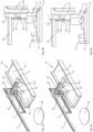
- Figures 5a, 5b and 6a, 6b each show an oblique view and a rear view of different procedural situations when separating piece goods.
- a suction head 41a of a suction gripper is placed on an upper side surface of a piece of goods 3.
- the suction pad in the embodiment shown comprises a central rotating body 42, which is rotatably mounted on a rotating body holder 46 about a horizontally formed axis of rotation.
- Two suction heads are arranged on the rotating body 42, namely the suction head 41a sitting on the piece goods 3 and the suction head 41b arranged opposite.
- the diameter of the suction head 41a is larger than that of the suction head 41b, ie the suction head 41a is intended for picking up larger piece goods or placing them on larger surfaces of piece goods.
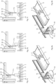
- Figures 7a, 7b and 7c show front views of further process situations according to a preferred embodiment of the method according to the invention.
- the piece goods 3 are placed on a storage surface 50, specifically in the “left” part of the storage surface.
- the largest support surface is a lateral surface of the piece goods aligned with the X direction, and in the case of the piece goods described here In a preferred embodiment, this largest side area is defined as the storage area.
- the conveyor device 40 is moved in such a way that the suction head 41a is arranged to the left of the piece goods 3 in such a way that the suction head is located below the upper edge of the piece goods 3.
- the suction pad on the Y-guide 44 is moved to the right, so that the piece goods 3 are knocked over with the suction head 41a.
- the result is that the general cargo, as it is in Figure 7c is shown, rests on the largest side surface determined as the storage surface. In this orientation, it can then be moved from an operating device (not shown) onto, for example, a storage conveyor of the picking device (also not shown), from where it is then moved to the final storage location.
- FIGS. 8a and 8b show oblique views of the in the Figures 7a and 7c procedural situations shown in order to illustrate them visually.
- a preferred embodiment of the method according to the invention for separating piece goods to be stored in a picking device is described below using the flow chart of Figure 9 described.
- a step 100 a plurality of non-singulated piece goods are provided in a receiving area 11 of a feed device 10, as described in more detail in the above figures.
- the piece goods can in particular be pharmaceutical packs which, after being separated using the device according to the invention, are to be stored in a pharmacy picking device.
- a 3D detection device arranged above the feed device (for example a simple 3D camera) a 3D image of the majority of piece goods was recorded.
- This 3D image is processed in a step 120 with a control device 30, which is coupled to the 3D detection device, and the position of the individual piece goods is determined.
- the next piece of cargo to be picked up is then determined from this, which is usually a piece of cargo that is not overlaid by other pieces of cargo. In the previous figures, this is, for example, the subsequently picked up piece of goods 3.
- the previously determined piece of goods is then picked up in a step 130 with a suction head 41a of the suction gripper, specifically on the side surface of the piece of goods, which is best accessible for the suction gripper.
- a 3D image of the piece goods picked up is created in a step 140 using a laterally arranged 3D detection device, which can also be a 3D camera.
- this 3D image is processed with the aim of determining the dimensions of the piece of goods recorded.
- the recorded piece of goods is rotated by a predetermined value around the Z-axis and another 3D image is created, which is subjected to corresponding processing according to step 150 becomes. This is repeated until all dimensions have been determined.
- its orientation is determined in a step 160.
- the control device of the device is regularly coupled to a control device of the picking device in which the piece goods are to be stored, and depending on the storage spaces available, the control device of the order picking device can, for example, specify that all piece goods are to be stored in such a way that their longest side surface, for example should be aligned in the Y direction.
- a step 180 the picked up piece goods are moved in the for example, is arranged laterally, the piece goods are arranged by tilting the piece goods with the suction cup after the first placement.
Landscapes
- Engineering & Computer Science (AREA)
- Mechanical Engineering (AREA)
- Physics & Mathematics (AREA)
- General Physics & Mathematics (AREA)
- Specific Conveyance Elements (AREA)
- Warehouses Or Storage Devices (AREA)
- Sorting Of Articles (AREA)
- Discharge Of Articles From Conveyors (AREA)
Claims (11)
- Dispositif (1) pour séparer des articles (2) à stocker dans un dispositif de préparation de commandes, présentant :un dispositif d'alimentation (10) pour la mise à disposition d'une pluralité d'articles non séparés dans une zone de réception (11) s'étendant dans une direction X et Y du dispositif,un dispositif de détection supérieur (20) disposé dans la direction Z, orthogonalement aux directions X et Y, au-dessus du dispositif d'alimentation (10), pour détecter des images d'articles (2, 3) disposés sur le dispositif d'alimentation (10) dans la zone de réception (11),un dispositif de commande (30) couplé au dispositif de détection supérieur (20) pour évaluer des images réalisées avec le dispositif de détection supérieur (20) et pour déterminer un article (3) à prélever parmi la pluralité d'articles,un dispositif de transport (40) couplé au dispositif de commande (30) avec un moyen de préhension (41a, 41b) pouvant tourner autour de l'axe Z pour prendre un article (2) déterminé par le dispositif de commande (30) parmi la pluralité d'articles,une surface de dépôt (50) disposée en aval de la zone de réception (11) dans la direction X pour déposer des articles reçus avec le dispositif de transport (40), caractérisé parun dispositif de détection latéral (60) pour établir au moins une image d'un article prise en charge (3) par le dispositif de transport (40), le dispositif de commande étant configuré de telle sorte que l'au moins une image établie avec le dispositif de détection latéral (60) est traitée pour déterminer les dimensions de l'article reçue, l'article reçue étant alors tournée d'un angle prédéfini autour de l'axe Z et une autre image étant établie si toutes les dimensions de l'article reçue ne peuvent pas être déterminées,et, sur la base des résultats du traitement d'image, l'orientation de l'article prise en charge est déterminée et, en fonction de consignes données par le dispositif de commande, la surface de stockage préférée de l'article prise en charge est déterminée,le dispositif de transport (40) étant commandé en fonction de l'orientation et de la surface de stockage préférée de telle sorte qu'un article reçue est disposée sur une surface de stockage préférée sur la surface de dépôt (50), le dispositif de détection (20) étant un dispositif de détection 3D d'images 3D.
- Dispositif (1) pour séparer des articles (2) à stocker dans un dispositif de préparation de commandes selon la revendication 1, caractérisé en ce que le dispositif de détection latéral (60) est conçu comme un dispositif de détection 3D.
- Dispositif (1) pour séparer des articles (2) à stocker dans un dispositif de préparation de commandes selon la revendication 1 ou 2, caractérisé en ce que le dispositif de transport (40) est conçu comme une ventouse mobile dans les directions X, Y et Z avec au moins une tête d'aspiration (41a) pouvant tourner autour de l'axe Z.
- Dispositif (1) pour séparer des articles (2) à stocker dans un dispositif de préparation de commandes selon la revendication 3, caractérisé en ce que la ventouse présente deux têtes d'aspiration (41a, 41b) de dimensions différentes.
- Dispositif (1) pour séparer des articles (2) à stocker dans un dispositif de préparation de commandes selon la revendication 4, caractérisé en ce que la ventouse (40) présente un corps rotatif (42) sur lequel sont disposées les têtes d'aspiration (41a, 41b), le corps rotatif (42) pouvant tourner autour d'un axe de rotation s'étendant horizontalement.
- Dispositif (1) pour séparer des articles (2) à stocker dans un dispositif de préparation de commandes selon l'une des revendications 1 à 5, caractérisé en ce que la surface de dépôt (50) est conçue de manière rotative.
- Procédé pour séparer des articles (2) à stocker dans un dispositif de préparation de commandes, dans lequela) avec un dispositif d'alimentation (10), une pluralité d'articles (2) non séparés sont disposés dans une zone de réception (11) s'étendant dans une direction X et Y,b) avec un dispositif de détection 3D supérieur (20), disposé dans la direction Z, orthogonalement aux directions X et Y, au-dessus du dispositif d'alimentation (10), on réalise au moins une image 3D de la pluralité d'articles non séparés (2),c) à l'aide d'un dispositif de commande (30) couplé au dispositif de détection 3D (20), on traite l'au moins une image 3D pour déterminer la position des articles non séparés (2) et on détermine quel article de la pluralité d'articles doit être pris en charge ensuite,d) l'article (3) déterminée à l'étape c) est saisie par un moyen de préhension (41a, 41b) pouvant tourner autour de l'axe Z d'un dispositif de transport (40),e) au moins une image de l'article prise en charge (3) est établie avec un dispositif de détection latéral (60) couplé au dispositif de commande (30),f) l'au moins une image réalisée avec le dispositif de détection latéral (60) est traitée pour déterminer les dimensions de l'article saisie,g) dans lequel, si toutes les dimensions de l'article prise en charge ne peuvent pas être déterminées, l'article prise en charge est tourné d'un angle prédéfini autour de l'axe Z et les étapes e) et f) sont répétées jusqu'à ce que toutes les dimensions de l'article prise en charge soient déterminées,h) l'orientation de l'article prise en charge est déterminée sur la base des résultats du traitement d'image et la surface de stockage préférée de l'article prise en charge est définie en fonction de consignes données par le dispositif de commande,i) l'article prise en charge (3) est déplacée vers une surface de dépôt (50) disposée en aval de la zone de réception (11) dans la direction X, etj) l'article prise en charge est placée sur une surface de stockage préférée sur la surface de dépôt (50).
- Procédé pour séparer des articles (2) à stocker dans un dispositif de préparation de commandes selon la revendication 7, caractérisé en ce que l'article prise en charge (3) est disposé sur une surface de stockage en étant d'abord disposé sur une autre surface de l'article prise en charge sur la surface de dépôt (50) et en étant ensuite basculé sur la surface de stockage.
- Procédé pour séparer des articles (2) à stocker dans un dispositif de préparation de commandes selon la revendication 7 ou 8, caractérisé en ce qu'une image 3D de l'article prise en charge est réalisée avec le dispositif de détection latéral (60) .
- Procédé pour séparer des articles (2) à stocker dans un dispositif de préparation de commandes selon l'une des revendications 7 à 9, caractérisé en ce que l'article prise en charge (3) est tournés autour de l'axe Z selon les indications du dispositif de commande avant d'être disposés sur la surface de dépôt (50).
- Procédé pour séparer des articles (2) à stocker dans un dispositif de préparation de commandes selon l'une des revendications 7 à 10, caractérisé en ce que l'article prise en charge est tournés autour de l'axe Z pour déterminer un identificateur et est balayé par le dispositif de détection latéral (60).
Priority Applications (9)
| Application Number | Priority Date | Filing Date | Title |
|---|---|---|---|
| ES20153602T ES2978595T3 (es) | 2020-01-24 | 2020-01-24 | Dispositivo y procedimiento para separar mercancías por piezas |
| EP20153602.6A EP3854731B1 (fr) | 2020-01-24 | 2020-01-24 | Dispositif et procédé de séparation de marchandises de détail |
| AU2020425487A AU2020425487B2 (en) | 2020-01-24 | 2020-12-15 | Device and method for individualizing piece goods |
| BR112022012552A BR112022012552A2 (pt) | 2020-01-24 | 2020-12-15 | Dispositivo e método para separação de artigos a serem armazenados em um dispositivo de coleta |
| PCT/EP2020/086178 WO2021148201A1 (fr) | 2020-01-24 | 2020-12-15 | Dispositif et procédé d'individualisation de marchandises à la pièce |
| JP2022544836A JP7682188B2 (ja) | 2020-01-24 | 2020-12-15 | ピースグッズを分離するためのデバイスおよび方法 |
| CA3162609A CA3162609A1 (fr) | 2020-01-24 | 2020-12-15 | Dispositif et methode pour separer des marchandises a la piece |
| KR1020227027655A KR102879180B1 (ko) | 2020-01-24 | 2020-12-15 | 개별 물품 분류를 위한 장치 및 방법 |
| CN202080094239.3A CN115003613B (zh) | 2020-01-24 | 2020-12-15 | 用于分离计件货物的设备和方法 |
Applications Claiming Priority (1)
| Application Number | Priority Date | Filing Date | Title |
|---|---|---|---|
| EP20153602.6A EP3854731B1 (fr) | 2020-01-24 | 2020-01-24 | Dispositif et procédé de séparation de marchandises de détail |
Publications (3)
| Publication Number | Publication Date |
|---|---|
| EP3854731A1 EP3854731A1 (fr) | 2021-07-28 |
| EP3854731C0 EP3854731C0 (fr) | 2024-03-20 |
| EP3854731B1 true EP3854731B1 (fr) | 2024-03-20 |
Family
ID=69191970
Family Applications (1)
| Application Number | Title | Priority Date | Filing Date |
|---|---|---|---|
| EP20153602.6A Active EP3854731B1 (fr) | 2020-01-24 | 2020-01-24 | Dispositif et procédé de séparation de marchandises de détail |
Country Status (9)
| Country | Link |
|---|---|
| EP (1) | EP3854731B1 (fr) |
| JP (1) | JP7682188B2 (fr) |
| KR (1) | KR102879180B1 (fr) |
| CN (1) | CN115003613B (fr) |
| AU (1) | AU2020425487B2 (fr) |
| BR (1) | BR112022012552A2 (fr) |
| CA (1) | CA3162609A1 (fr) |
| ES (1) | ES2978595T3 (fr) |
| WO (1) | WO2021148201A1 (fr) |
Families Citing this family (2)
| Publication number | Priority date | Publication date | Assignee | Title |
|---|---|---|---|---|
| CN114011730B (zh) * | 2022-01-06 | 2022-06-07 | 江苏华宇印涂设备集团有限公司 | 一种基于智能控制的三收料系统以及操作方法 |
| CN117446253B (zh) * | 2023-10-31 | 2025-10-28 | 广西中烟工业有限责任公司 | 烟支输送管道横烟处理装置及处理方法 |
Family Cites Families (20)
| Publication number | Priority date | Publication date | Assignee | Title |
|---|---|---|---|---|
| ES2104219T5 (es) * | 1993-04-10 | 2002-04-01 | Christoph Schausten | Procedimiento para el almacenamiento de material embalado y dispositivo para la realizacion del procedimiento. |
| DE4318341B4 (de) * | 1993-04-10 | 2009-02-19 | Christoph Schausten | Verfahren zur Lagerung von Apotheken-Artikeln und Vorrichtung zur Durchführung eines solchen Verfahrens |
| DE10225332B4 (de) * | 2002-06-06 | 2006-11-16 | Wagner, Rudolf M., Dipl.-Ing. | Einlagerungspuffer und Verfahren zum Einlagern von Stückgütern für ein automatisiertes Stückgutlager |
| FI126245B (fi) * | 2005-03-09 | 2016-08-31 | Konecranes Finland Oy | Menetelmä paletittoman tavarakollin sijoittamiseksi ja luovuttamiseksi varastohyllystä ja kollien logistiikan hallitsemiseksi sekä laitteisto menetelmän toteuttamiseksi |
| ATE373614T1 (de) * | 2005-07-28 | 2007-10-15 | Rowa Automatisierungssysteme | Verfahren und vorrichtung zum vermessen und positionieren eines quaderförmigen stückguts |
| DE102007007411A1 (de) * | 2007-02-12 | 2008-08-14 | Michael Marquardt | Verfahren und Vorrichtung zum Einlagern von Arzneimittelpackungen |
| JP4829262B2 (ja) | 2008-02-20 | 2011-12-07 | アキム株式会社 | 搬送装置 |
| DE102010060449B4 (de) * | 2010-11-09 | 2022-04-28 | Wincor Nixdorf International Gmbh | Vorrichtung und Verfahren zum Erfassen von Waren an einem Selbstbedienungskassensystem |
| ITTO20110377A1 (it) * | 2011-04-29 | 2012-10-30 | Syco S A S Di Haberl & C | Sistema di magazzino automatizzato per articoli di forma parallelepipeda, in particolare confezioni di medicinali o simili, operante in ambiente non strutturato |
| EP2718211B1 (fr) | 2011-06-07 | 2015-09-30 | CareFusion Germany 326 GmbH | Dispositif de séparation de colis isolés devant être stockés dans un entrepôt automatisé |
| SG2013069893A (en) | 2013-09-13 | 2015-04-29 | Jcs Echigo Pte Ltd | Material handling system and method |
| KR101661665B1 (ko) * | 2016-03-21 | 2016-10-04 | (주)디엠소프트 | 3차원 비전 시스템을 이용한 용접 품질 검사 장치 및 방법 |
| EP3339192B1 (fr) * | 2016-12-21 | 2019-03-06 | UHLMANN PAC-SYSTEME GmbH & Co. KG | Procédé pour le transfert d'emballages blister |
| KR101918921B1 (ko) * | 2017-01-12 | 2018-11-15 | 인곡산업 주식회사 | 엔드밀 치핑을 검사하는 비전검사장치 및 그 방법 |
| DE102017205001B4 (de) * | 2017-03-24 | 2025-10-02 | Krones Aktiengesellschaft | Vorrichtung und Verfahren zum Umgang mit bewegten Stückgütern sowie Förder-, Verarbeitungs- und/oder Verpackungsanlage für Stückgüter |
| JP6955905B2 (ja) | 2017-05-29 | 2021-10-27 | コマニー株式会社 | パラレルリンクロボット用ロボットハンド及びパラレルリンクロボット |
| JP6937200B2 (ja) | 2017-09-12 | 2021-09-22 | 株式会社東芝 | 物品移動装置、物品移動方法、および物品移動制御プログラム |
| JP2020007145A (ja) | 2018-07-12 | 2020-01-16 | 株式会社東芝 | 物品移動装置および制御装置 |
| CN209651355U (zh) | 2018-12-04 | 2019-11-19 | 湖北航天技术研究院计量测试技术研究所 | 电子元器件自动上料装置 |
| US10583560B1 (en) | 2019-04-03 | 2020-03-10 | Mujin, Inc. | Robotic system with object identification and handling mechanism and method of operation thereof |
-
2020
- 2020-01-24 EP EP20153602.6A patent/EP3854731B1/fr active Active
- 2020-01-24 ES ES20153602T patent/ES2978595T3/es active Active
- 2020-12-15 AU AU2020425487A patent/AU2020425487B2/en active Active
- 2020-12-15 CA CA3162609A patent/CA3162609A1/fr active Pending
- 2020-12-15 KR KR1020227027655A patent/KR102879180B1/ko active Active
- 2020-12-15 WO PCT/EP2020/086178 patent/WO2021148201A1/fr not_active Ceased
- 2020-12-15 CN CN202080094239.3A patent/CN115003613B/zh active Active
- 2020-12-15 JP JP2022544836A patent/JP7682188B2/ja active Active
- 2020-12-15 BR BR112022012552A patent/BR112022012552A2/pt unknown
Also Published As
| Publication number | Publication date |
|---|---|
| ES2978595T3 (es) | 2024-09-16 |
| AU2020425487B2 (en) | 2026-03-26 |
| JP7682188B2 (ja) | 2025-05-23 |
| JP2023511584A (ja) | 2023-03-20 |
| KR102879180B1 (ko) | 2025-10-30 |
| AU2020425487A1 (en) | 2022-07-21 |
| EP3854731A1 (fr) | 2021-07-28 |
| WO2021148201A1 (fr) | 2021-07-29 |
| BR112022012552A2 (pt) | 2022-09-06 |
| EP3854731C0 (fr) | 2024-03-20 |
| KR20220127864A (ko) | 2022-09-20 |
| CA3162609A1 (fr) | 2021-07-29 |
| CN115003613A (zh) | 2022-09-02 |
| CN115003613B (zh) | 2025-08-08 |
Similar Documents
| Publication | Publication Date | Title |
|---|---|---|
| DE102014016072B4 (de) | Vorrichtung und Verfahren zum Aufheben eines willkürlich aufgestapelten Gegenstands mittels eines Roboters | |
| DE102013109220B4 (de) | Robotervorrichtung und Verfahren zum Herausnehmen von Bulk-Ware aus einem Lager | |
| EP3363043B1 (fr) | Dispositif de manipulation de composants | |
| DE102018116855B4 (de) | Transportvorrichtung mit einer Zuführeinrichtung, die Werkstücke im Kreis laufen lässt | |
| EP4201852B1 (fr) | Poste de préparation de commandes et procédé automatique de commandes de marchandises | |
| DE102018116967B4 (de) | Zuführeinrichtung, die Werkstücke einer Entnahmevorrichtung zuführt, sowie mit der Zuführeinrichtung versehene Transportvorrichtung | |
| DE102015102740A1 (de) | Vorrichtung und Verfahren zur Anordnung von Gegenständen mittels eines Roboters und Gegenstand-Transportsystem | |
| DE102012012988A1 (de) | Vorrichtung zur automatisierten Handhabung von Werkstücken | |
| DE102016208995B4 (de) | Regalsystem umfassend eine Anordnung zur Konturenkontrolle von in ein Regalsystem einzulagernden Paletten | |
| WO2016023672A1 (fr) | Dispositif et procédé de contrôle de contours basé sur des caméras | |
| US12552617B2 (en) | Device and method for separating piece goods | |
| EP3854731B1 (fr) | Dispositif et procédé de séparation de marchandises de détail | |
| AT508588A1 (de) | Verfahren zur beladung eines ladungsträgers mit ladeeinheiten | |
| EP3533730A1 (fr) | Dispositif de préparation de commandes destiné à entreposer une pluralité de marchandises de détail identiques | |
| EP4010276B1 (fr) | Dispositif et procédé de manutention et/ou de manipulation d'au moins une rangée de marchandises de détail en défilement | |
| DE102005053296B4 (de) | Verfahren und Vorrichtung zum automatisierten Stapeln von Reifen auf einem Träger | |
| EP2531962A1 (fr) | Système de stockage pour stocker des articles et préparer des commandes d'articles, en particulier des articles de pharmacie | |
| DE10356536B4 (de) | Entnahme- und Ablagevorrichtung | |
| EP3854730B1 (fr) | Dispositif et procédé d'identification, de mesure et de positionnement de marchandises de détail | |
| DE102008037552B4 (de) | Verfahren und Vorrichtung zur Positionsbestimmung von Werkstücken | |
| DE102012013023A1 (de) | Vorrichtung zur automatisierten Handhabung von Werkstücken | |
| DE2601027B2 (de) | Verfahren und Vorrichtung zum Aufnehmen einer vorbestimmten Anzahl von Gegenstanden aus einem Vorrat | |
| WO2024110100A1 (fr) | Procédé de stockage d'une pluralité de marchandises à la pièce dans un dispositif de préparation de commandes | |
| AT509024B1 (de) | Verfahren zur bestimmung der ausrichtung eines oberen teils eines stückgutstapels | |
| DE102019106068B3 (de) | System zur beseitigung von überlagerungen zufällig angeordneter werkstücke |
Legal Events
| Date | Code | Title | Description |
|---|---|---|---|
| PUAI | Public reference made under article 153(3) epc to a published international application that has entered the european phase |
Free format text: ORIGINAL CODE: 0009012 |
|
| STAA | Information on the status of an ep patent application or granted ep patent |
Free format text: STATUS: THE APPLICATION HAS BEEN PUBLISHED |
|
| AK | Designated contracting states |
Kind code of ref document: A1 Designated state(s): AL AT BE BG CH CY CZ DE DK EE ES FI FR GB GR HR HU IE IS IT LI LT LU LV MC MK MT NL NO PL PT RO RS SE SI SK SM TR |
|
| STAA | Information on the status of an ep patent application or granted ep patent |
Free format text: STATUS: REQUEST FOR EXAMINATION WAS MADE |
|
| 17P | Request for examination filed |
Effective date: 20220128 |
|
| RBV | Designated contracting states (corrected) |
Designated state(s): AL AT BE BG CH CY CZ DE DK EE ES FI FR GB GR HR HU IE IS IT LI LT LU LV MC MK MT NL NO PL PT RO RS SE SI SK SM TR |
|
| GRAP | Despatch of communication of intention to grant a patent |
Free format text: ORIGINAL CODE: EPIDOSNIGR1 |
|
| STAA | Information on the status of an ep patent application or granted ep patent |
Free format text: STATUS: GRANT OF PATENT IS INTENDED |
|
| RIC1 | Information provided on ipc code assigned before grant |
Ipc: B65G 47/91 20060101ALN20231116BHEP Ipc: B65G 1/137 20060101ALN20231116BHEP Ipc: G01B 5/08 20060101ALI20231116BHEP Ipc: B65G 47/32 20060101AFI20231116BHEP |
|
| INTG | Intention to grant announced |
Effective date: 20231129 |
|
| GRAS | Grant fee paid |
Free format text: ORIGINAL CODE: EPIDOSNIGR3 |
|
| GRAA | (expected) grant |
Free format text: ORIGINAL CODE: 0009210 |
|
| STAA | Information on the status of an ep patent application or granted ep patent |
Free format text: STATUS: THE PATENT HAS BEEN GRANTED |
|
| AK | Designated contracting states |
Kind code of ref document: B1 Designated state(s): AL AT BE BG CH CY CZ DE DK EE ES FI FR GB GR HR HU IE IS IT LI LT LU LV MC MK MT NL NO PL PT RO RS SE SI SK SM TR |
|
| REG | Reference to a national code |
Ref country code: GB Ref legal event code: FG4D Free format text: NOT ENGLISH |
|
| REG | Reference to a national code |
Ref country code: CH Ref legal event code: EP |
|
| REG | Reference to a national code |
Ref country code: DE Ref legal event code: R096 Ref document number: 502020007376 Country of ref document: DE |
|
| REG | Reference to a national code |
Ref country code: IE Ref legal event code: FG4D Free format text: LANGUAGE OF EP DOCUMENT: GERMAN |
|
| U01 | Request for unitary effect filed |
Effective date: 20240320 |
|
| U07 | Unitary effect registered |
Designated state(s): AT BE BG DE DK EE FI FR IT LT LU LV MT NL PT SE SI Effective date: 20240328 |
|
| PG25 | Lapsed in a contracting state [announced via postgrant information from national office to epo] |
Ref country code: GR Free format text: LAPSE BECAUSE OF FAILURE TO SUBMIT A TRANSLATION OF THE DESCRIPTION OR TO PAY THE FEE WITHIN THE PRESCRIBED TIME-LIMIT Effective date: 20240621 |
|
| PG25 | Lapsed in a contracting state [announced via postgrant information from national office to epo] |
Ref country code: RS Free format text: LAPSE BECAUSE OF FAILURE TO SUBMIT A TRANSLATION OF THE DESCRIPTION OR TO PAY THE FEE WITHIN THE PRESCRIBED TIME-LIMIT Effective date: 20240620 Ref country code: HR Free format text: LAPSE BECAUSE OF FAILURE TO SUBMIT A TRANSLATION OF THE DESCRIPTION OR TO PAY THE FEE WITHIN THE PRESCRIBED TIME-LIMIT Effective date: 20240320 |
|
| PG25 | Lapsed in a contracting state [announced via postgrant information from national office to epo] |
Ref country code: RS Free format text: LAPSE BECAUSE OF FAILURE TO SUBMIT A TRANSLATION OF THE DESCRIPTION OR TO PAY THE FEE WITHIN THE PRESCRIBED TIME-LIMIT Effective date: 20240620 Ref country code: NO Free format text: LAPSE BECAUSE OF FAILURE TO SUBMIT A TRANSLATION OF THE DESCRIPTION OR TO PAY THE FEE WITHIN THE PRESCRIBED TIME-LIMIT Effective date: 20240620 Ref country code: HR Free format text: LAPSE BECAUSE OF FAILURE TO SUBMIT A TRANSLATION OF THE DESCRIPTION OR TO PAY THE FEE WITHIN THE PRESCRIBED TIME-LIMIT Effective date: 20240320 Ref country code: GR Free format text: LAPSE BECAUSE OF FAILURE TO SUBMIT A TRANSLATION OF THE DESCRIPTION OR TO PAY THE FEE WITHIN THE PRESCRIBED TIME-LIMIT Effective date: 20240621 |
|
| REG | Reference to a national code |
Ref country code: ES Ref legal event code: FG2A Ref document number: 2978595 Country of ref document: ES Kind code of ref document: T3 Effective date: 20240916 |
|
| PG25 | Lapsed in a contracting state [announced via postgrant information from national office to epo] |
Ref country code: IS Free format text: LAPSE BECAUSE OF FAILURE TO SUBMIT A TRANSLATION OF THE DESCRIPTION OR TO PAY THE FEE WITHIN THE PRESCRIBED TIME-LIMIT Effective date: 20240720 |
|
| PG25 | Lapsed in a contracting state [announced via postgrant information from national office to epo] |
Ref country code: SM Free format text: LAPSE BECAUSE OF FAILURE TO SUBMIT A TRANSLATION OF THE DESCRIPTION OR TO PAY THE FEE WITHIN THE PRESCRIBED TIME-LIMIT Effective date: 20240320 |
|
| PG25 | Lapsed in a contracting state [announced via postgrant information from national office to epo] |
Ref country code: CZ Free format text: LAPSE BECAUSE OF FAILURE TO SUBMIT A TRANSLATION OF THE DESCRIPTION OR TO PAY THE FEE WITHIN THE PRESCRIBED TIME-LIMIT Effective date: 20240320 |
|
| PG25 | Lapsed in a contracting state [announced via postgrant information from national office to epo] |
Ref country code: PL Free format text: LAPSE BECAUSE OF FAILURE TO SUBMIT A TRANSLATION OF THE DESCRIPTION OR TO PAY THE FEE WITHIN THE PRESCRIBED TIME-LIMIT Effective date: 20240320 |
|
| PG25 | Lapsed in a contracting state [announced via postgrant information from national office to epo] |
Ref country code: SK Free format text: LAPSE BECAUSE OF FAILURE TO SUBMIT A TRANSLATION OF THE DESCRIPTION OR TO PAY THE FEE WITHIN THE PRESCRIBED TIME-LIMIT Effective date: 20240320 |
|
| PG25 | Lapsed in a contracting state [announced via postgrant information from national office to epo] |
Ref country code: SM Free format text: LAPSE BECAUSE OF FAILURE TO SUBMIT A TRANSLATION OF THE DESCRIPTION OR TO PAY THE FEE WITHIN THE PRESCRIBED TIME-LIMIT Effective date: 20240320 Ref country code: SK Free format text: LAPSE BECAUSE OF FAILURE TO SUBMIT A TRANSLATION OF THE DESCRIPTION OR TO PAY THE FEE WITHIN THE PRESCRIBED TIME-LIMIT Effective date: 20240320 Ref country code: RO Free format text: LAPSE BECAUSE OF FAILURE TO SUBMIT A TRANSLATION OF THE DESCRIPTION OR TO PAY THE FEE WITHIN THE PRESCRIBED TIME-LIMIT Effective date: 20240320 Ref country code: PL Free format text: LAPSE BECAUSE OF FAILURE TO SUBMIT A TRANSLATION OF THE DESCRIPTION OR TO PAY THE FEE WITHIN THE PRESCRIBED TIME-LIMIT Effective date: 20240320 Ref country code: IS Free format text: LAPSE BECAUSE OF FAILURE TO SUBMIT A TRANSLATION OF THE DESCRIPTION OR TO PAY THE FEE WITHIN THE PRESCRIBED TIME-LIMIT Effective date: 20240720 Ref country code: CZ Free format text: LAPSE BECAUSE OF FAILURE TO SUBMIT A TRANSLATION OF THE DESCRIPTION OR TO PAY THE FEE WITHIN THE PRESCRIBED TIME-LIMIT Effective date: 20240320 |
|
| REG | Reference to a national code |
Ref country code: DE Ref legal event code: R097 Ref document number: 502020007376 Country of ref document: DE |
|
| U20 | Renewal fee for the european patent with unitary effect paid |
Year of fee payment: 6 Effective date: 20241218 |
|
| PLBE | No opposition filed within time limit |
Free format text: ORIGINAL CODE: 0009261 |
|
| STAA | Information on the status of an ep patent application or granted ep patent |
Free format text: STATUS: NO OPPOSITION FILED WITHIN TIME LIMIT |
|
| 26N | No opposition filed |
Effective date: 20241223 |
|
| PG25 | Lapsed in a contracting state [announced via postgrant information from national office to epo] |
Ref country code: MC Free format text: LAPSE BECAUSE OF FAILURE TO SUBMIT A TRANSLATION OF THE DESCRIPTION OR TO PAY THE FEE WITHIN THE PRESCRIBED TIME-LIMIT Effective date: 20240320 |
|
| PGFP | Annual fee paid to national office [announced via postgrant information from national office to epo] |
Ref country code: GB Payment date: 20251219 Year of fee payment: 7 |
|
| PG25 | Lapsed in a contracting state [announced via postgrant information from national office to epo] |
Ref country code: IE Free format text: LAPSE BECAUSE OF NON-PAYMENT OF DUE FEES Effective date: 20250124 |
|
| U20 | Renewal fee for the european patent with unitary effect paid |
Year of fee payment: 7 Effective date: 20251217 |
|
| REG | Reference to a national code |
Ref country code: CH Ref legal event code: U11 Free format text: ST27 STATUS EVENT CODE: U-0-0-U10-U11 (AS PROVIDED BY THE NATIONAL OFFICE) Effective date: 20260201 |
|
| PGFP | Annual fee paid to national office [announced via postgrant information from national office to epo] |
Ref country code: ES Payment date: 20260202 Year of fee payment: 7 |
|
| PGFP | Annual fee paid to national office [announced via postgrant information from national office to epo] |
Ref country code: CH Payment date: 20260201 Year of fee payment: 7 |