EP4201852B1 - Poste de préparation de commandes et procédé automatique de commandes de marchandises - Google Patents
Poste de préparation de commandes et procédé automatique de commandes de marchandises Download PDFInfo
- Publication number
- EP4201852B1 EP4201852B1 EP23154647.4A EP23154647A EP4201852B1 EP 4201852 B1 EP4201852 B1 EP 4201852B1 EP 23154647 A EP23154647 A EP 23154647A EP 4201852 B1 EP4201852 B1 EP 4201852B1
- Authority
- EP
- European Patent Office
- Prior art keywords
- container
- target
- conveyor
- source
- containers
- Prior art date
- Legal status (The legal status is an assumption and is not a legal conclusion. Google has not performed a legal analysis and makes no representation as to the accuracy of the status listed.)
- Active
Links
Images











Classifications
-
- B—PERFORMING OPERATIONS; TRANSPORTING
- B25—HAND TOOLS; PORTABLE POWER-DRIVEN TOOLS; MANIPULATORS
- B25J—MANIPULATORS; CHAMBERS PROVIDED WITH MANIPULATION DEVICES
- B25J15/00—Gripping heads and other end effectors
- B25J15/06—Gripping heads and other end effectors with vacuum or magnetic holding means
- B25J15/0616—Gripping heads and other end effectors with vacuum or magnetic holding means with vacuum
-
- B—PERFORMING OPERATIONS; TRANSPORTING
- B25—HAND TOOLS; PORTABLE POWER-DRIVEN TOOLS; MANIPULATORS
- B25J—MANIPULATORS; CHAMBERS PROVIDED WITH MANIPULATION DEVICES
- B25J9/00—Program-controlled manipulators
- B25J9/16—Program controls
- B25J9/1694—Program controls characterised by use of sensors other than normal servo-feedback from position, speed or acceleration sensors, perception control, multi-sensor controlled systems, sensor fusion
- B25J9/1697—Vision controlled systems
-
- B—PERFORMING OPERATIONS; TRANSPORTING
- B65—CONVEYING; PACKING; STORING; HANDLING THIN OR FILAMENTARY MATERIAL
- B65G—TRANSPORT OR STORAGE DEVICES, e.g. CONVEYORS FOR LOADING OR TIPPING, SHOP CONVEYOR SYSTEMS OR PNEUMATIC TUBE CONVEYORS
- B65G1/00—Storing articles, individually or in orderly arrangement, in warehouses or magazines
- B65G1/02—Storage devices
- B65G1/04—Storage devices mechanical
- B65G1/137—Storage devices mechanical with arrangements or automatic control means for selecting which articles are to be removed
- B65G1/1373—Storage devices mechanical with arrangements or automatic control means for selecting which articles are to be removed for fulfilling orders in warehouses
- B65G1/1378—Storage devices mechanical with arrangements or automatic control means for selecting which articles are to be removed for fulfilling orders in warehouses the orders being assembled on fixed commissioning areas remote from the storage areas
-
- B—PERFORMING OPERATIONS; TRANSPORTING
- B65—CONVEYING; PACKING; STORING; HANDLING THIN OR FILAMENTARY MATERIAL
- B65G—TRANSPORT OR STORAGE DEVICES, e.g. CONVEYORS FOR LOADING OR TIPPING, SHOP CONVEYOR SYSTEMS OR PNEUMATIC TUBE CONVEYORS
- B65G47/00—Article or material-handling devices associated with conveyors; Methods employing such devices
- B65G47/52—Devices for transferring articles or materials between conveyors i.e. discharging or feeding devices
-
- B—PERFORMING OPERATIONS; TRANSPORTING
- B65—CONVEYING; PACKING; STORING; HANDLING THIN OR FILAMENTARY MATERIAL
- B65G—TRANSPORT OR STORAGE DEVICES, e.g. CONVEYORS FOR LOADING OR TIPPING, SHOP CONVEYOR SYSTEMS OR PNEUMATIC TUBE CONVEYORS
- B65G47/00—Article or material-handling devices associated with conveyors; Methods employing such devices
- B65G47/52—Devices for transferring articles or materials between conveyors i.e. discharging or feeding devices
- B65G47/66—Fixed platforms or combs, e.g. bridges between conveyors
-
- B—PERFORMING OPERATIONS; TRANSPORTING
- B65—CONVEYING; PACKING; STORING; HANDLING THIN OR FILAMENTARY MATERIAL
- B65G—TRANSPORT OR STORAGE DEVICES, e.g. CONVEYORS FOR LOADING OR TIPPING, SHOP CONVEYOR SYSTEMS OR PNEUMATIC TUBE CONVEYORS
- B65G47/00—Article or material-handling devices associated with conveyors; Methods employing such devices
- B65G47/74—Feeding, transfer, or discharging devices of particular kinds or types
- B65G47/90—Devices for picking-up and depositing articles or materials
- B65G47/91—Devices for picking-up and depositing articles or materials incorporating pneumatic, e.g. suction, grippers
- B65G47/914—Devices for picking-up and depositing articles or materials incorporating pneumatic, e.g. suction, grippers provided with drive systems incorporating rotary and rectilinear movements
-
- B—PERFORMING OPERATIONS; TRANSPORTING
- B65—CONVEYING; PACKING; STORING; HANDLING THIN OR FILAMENTARY MATERIAL
- B65G—TRANSPORT OR STORAGE DEVICES, e.g. CONVEYORS FOR LOADING OR TIPPING, SHOP CONVEYOR SYSTEMS OR PNEUMATIC TUBE CONVEYORS
- B65G2203/00—Indexing code relating to control or detection of the articles or the load carriers during conveying
- B65G2203/04—Detection means
- B65G2203/041—Camera
Definitions
- the invention relates to a picking station for picking goods from source containers into target containers.
- the US 2014/0244026 A1 discloses the preamble of patent claim 1, in particular a picking station for picking goods from source containers into target containers, comprising a first conveyor system for the automated transport of source containers and target containers, delivery devices for providing source containers and target containers, a second conveyor system for the automated removal of source containers and target containers, a fully automated robot system with an articulated arm robot on a gantry and a camera system for detecting the goods in the source container, and a robot controller which is connected to the sensor system and controls the articulated arm robot with a gripping unit.
- a picking station for picking goods from source container to target container is also available from the WO 2016/163666 A1 known, which comprises a source container conveyor system for the automated transport of source containers, a target container conveyor system for the automated transport of target containers, a fully automated robot system with a robot, and a sensor system for detecting the goods in the source container.
- the sensor system is arranged at a distance from the robot so that the goods in the source container are detected and a product is removed from the source container at various staging positions.
- a gantry arm that can rotate through an angle of rotation (DW) relative to the vertical axis can be attached to the robot.
- the gantry arm is equipped with a gripper unit that can pivot through an angle of articulation (W) in a single direction relative to the horizontal axis.
- the WO 2016/138101 A1 creates a list of location data of items in the scanned source container.
- the goods are picked based on the location data of the goods in the source container.
- the goods are picked from this "pick list" one after the other until the source container is completely empty. Multiple goods picks can occur without recapturing the image. However, this ignores the fact that goods can slip between individual picks and be lost during the next picking process. It cannot be guaranteed that the goods can be picked correctly or at all. This results in numerous disruptions and low picking performance.
- a picking station for the fully automated picking of various goods with a single robot is also available from the EP 2 984 007 B1 and the EP 2 315 714 B1 This means that orders can only be processed sequentially, which means that the picking performance of the picking station is rather low.
- a picking station is known in which several robots are moved relative to the source containers arranged one behind the other on a conveyor. Each robot is equipped with a gripping unit. The goods are removed from the source containers and placed on a storage rack.
- a gantry robot of the type mentioned is also fundamentally DE 44 07 324 A1 , US 5,564,893 A1 and JPS 52-59475 A1
- the known types of gantry robots are not suitable, or only inadequately, for picking goods.
- One object of the invention is therefore to provide an improved picking station for picking goods from source containers to target containers.
- the above-mentioned disadvantages are to be overcome and high picking performance is to be achieved.
- the picking process is to be carried out with exceptional reliability, thus minimizing disruptions.
- the robot system may comprise only a single robot which can access more than one source container, in particular the first source container and second source container, and more than one target container, in particular the first target container and second target container.
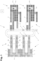
- a storage and picking system for picking goods comprising a storage area 1 and one or more picking stations 2 for picking goods with a robot system, a source container distribution system 3 and a target container distribution system 4.
- the storage area 1 shown as an example is primarily used to provide a large number of source containers 5, in which Fig. 2 represented goods A, B, etc., namely (warehouse) items are contained.
- the source containers 5 can each contain a single type of goods.
- a first source container 5a contains goods A
- a second source container 5b contains goods B, etc.
- the source containers 5 can be divided into several receiving compartments by partition walls and can accommodate different types of goods, whereby the first receiving compartment can accommodate goods A and the second receiving compartment can accommodate goods B.
- the range of goods in the storage area 1 can be increased.
- the target containers can be divided into several compartments by partition walls and to accommodate different orders, with the first compartment holding a first order with one or more items and the second compartment holding a second order with one or more items.
- the target containers can also be designed without partition walls and accommodate different orders.
- the storage area 1 preferably comprises an automated warehouse. According to the exemplary embodiment shown, the storage area 1 comprises parallel storage racks 6 and a rack aisle 7 provided between the storage racks 6. Each storage rack 6 forms a plurality of storage locations 8, on which the source containers 5 are stored, in stacked rack levels. In the example shown, two storage racks 6 are shown. Within the scope of the invention, however, more than two storage racks 6 can also be provided, with a rack aisle 7 being formed between each adjacent storage rack 6.
- the source container distribution system 3 is used to transport source containers 5 between the storage area 1 and the picking station(s) 2.
- the source container distribution system 3 is preferably an automated source container distribution system.
- the retrieval of source containers 5 from the storage area 1 and the transport of the source containers 5 from the storage area 1 to the picking station 2 can be automated.
- the source container distribution system 3 comprises, for example, one or more storage and retrieval devices 9 and a source container conveyor system between the storage area 1 and the picking stations 2 in order to transport source containers 5 from the storage area 1 to the respective picking stations 2 and to transport source containers 5 from the picking stations 2 to the storage area 1.
- the source container conveyor system between the storage area 1 and the picking stations 2 can, for example, comprise a first conveyor device 10 for transporting source containers 5 to the storage area 1 and a second conveyor device 11 for transporting source containers 5 away from the storage area 1 and a third conveyor device 12 for transporting source containers 5 to the picking station 2 and a fourth conveyor device 13 for transporting source containers 5 away from the picking station 2 and finally a fifth Conveyor device 14 for transporting source containers 5 between the conveyor devices 10, 11, 12, 13.
- the fifth conveyor device 14 comprises infeed and/or outfeed devices 15 for transporting the source containers 5 between the conveyor devices 10 to 14.
- the fifth conveyor device 14 is, for example, a closed conveyor loop.
- the infeed and/or outfeed device 15 is formed, for example, by a belt transfer device.
- the storage and retrieval device 9 comprises a loading platform and a transport device 18 (load-handling device).
- the transport device 18 can manipulate the source containers 5 between the loading platform and the storage location 8, namely, store source containers 5 in the storage racks 6 arranged on both sides of the storage and retrieval device 9 or retrieve source containers 5 from the storage racks 6 arranged on both sides of the storage and retrieval device 9. It can be provided that at least one storage and retrieval device 9 is assigned to each rack level. Thus, one storage and retrieval device 9 serves one rack level via the transport device 18.
- the buffer device 19a comprises, on each travel level, provision devices for the temporary buffering of one or more source containers 5 to be stored, and the buffer device 19b comprises, on each travel level, provision devices for the temporary buffering of one or more source containers 5 to be retrieved.
- Other design variants are also possible, as shown in the WO 2013/090970 A2 described.
- the lifting devices 20a, 20b are stationary and each comprise a transfer device that can be raised and lowered via a lifting drive.
- the transfer devices are each mounted on a vertical mast and each comprise a drivable conveyor device.
- the source container distribution system 3 may comprise an optional turning station 23 with which the source containers 5 discharged from the fifth conveyor device 14 are rotated from a transverse orientation into a longitudinal orientation.
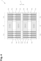
- the picking station 2 comprises a source container conveyor system for the automated transport of the source containers 5, in particular for transporting source containers 5 to a first delivery device 24a and a second delivery device 24b and for transporting source containers away from the first delivery device 24a and the second delivery device 24b.
- the source container conveyor technology of picking station 2 comprises a first conveyor device 25 for transporting source containers 5a, 5b, the first supply device 24a for providing a first source container 5a, a second supply device 24b for providing a second source container 5b and a second conveyor device 26 for transporting the source containers 5a, 5b away from the first supply device 24a and second supply device 24b.
- the first conveyor device 25 and second conveyor device 26 each comprise at least one conveyor means 22a, 22b.
- the conveyor means 22a is driven and coupled to a drive motor.
- the conveyor means 22a has, for example, conveyor rollers rotatably mounted on a frame.
- the conveyor means 22b is driven and coupled to a drive motor.
- the conveyor means 22b has, for example, conveyor rollers rotatably mounted on a frame.
- the first conveyor device 25 and second conveyor device 26 are preferably formed by a roller conveyor and comprise a plurality of conveyor rollers, at least some of which are driven by a drive motor.
- the first supply device 24a is connected to the first conveyor device 25 by means of conveying technology and includes a first removal station 27a.
- the first supply device 24a is connected to the first conveyor device 25 by means of a first transfer device 28.
- a first source container 5a is transported by the first conveyor device 25 and subsequently transported by the first transfer device 28 to the first supply device 24a at the first removal station 27a.
- the first source container 5a is then provided (upright) at the first removal station 27a.
- the second supply device 24b is connected to the first conveyor device 25 by means of conveying technology and includes a second removal station 27b.
- the second supply device 24b is connected to the first conveyor device 25 by means of a second transfer device 29.
- a second source container 5b is transported by the first conveyor device 25 and subsequently transported by the second transfer device 29 to the second supply device 24b at the second removal station 27b.
- the second source container 5b is then provided (upright) at the second removal station 27b.
- the first transfer device 28 and second transfer device 29 each comprise a first conveyor 30a and a second conveyor 30b, which are formed, for example, by a first belt transfer device and a second belt transfer device.
- Such belt transfer devices (and this also applies to the belt transfer devices mentioned elsewhere) have conveyor belts coupled to a drive motor, which are mounted on a lifting mechanism and form the conveying plane.
- the conveyor belts of the first belt transfer device can be adjusted via the lifting mechanism between a lowered rest position, in which the conveyor belts are lowered below the conveying plane of the first conveyor device 25 and a source container 5b is transported from the first conveyor device 25 to the second transfer device 29, and a raised conveying position, in which a source container 5a, 5b is lifted from the first conveyor device 25 and conveyed via the conveyor belts transversely to the first conveyor device 25.
- the conveyor belts of the second belt transfer device can be adjusted via the lifting mechanism between a raised conveying position, in which a source container 5a, 5b is taken over by the first belt transfer device and conveyed via the conveyor belts transversely to the second conveyor device 26, and a lowered rest position, in which the conveyor belts are lowered below the conveying plane of the second conveyor device 26 and a source container 5a, 5b is placed on the second conveyor device 26.
- the first supply device 24a with the first removal location 27a and the second supply device 24b with the second removal location 27b are formed on the second conveyor device 26 for the removal of source containers 5a, 5b.
- the first supply device 24a with the first removal location 27a and the second supply device 24b with the second removal location 27b are formed by conveyor sections on the second conveyor device 26 for the removal of source containers 5a, 5b.
- These conveyor sections each comprise a control unit 31 ( Fig. 1 ) controllable and drivable conveyor means 22b.
- the conveyor means 22b comprises a plurality of conveyor rollers, at least some of which are driven by a drive motor.
- the first conveyor device 25 and the second conveyor device 26 have opposite conveying directions, as shown in the Fig. 3 and 4 indicated by the arrows.
- the conveying means 22a of the first conveying device 25 are driven unidirectionally
- the conveying means 22b of the second conveying device 26 are driven unidirectionally.
- Picking station 2 is connected to the source container conveyor system of the source container distribution system. Specifically, picking station 2 connects to the third conveyor 12 via the first conveyor 25 and to the fourth conveyor 13 via the second conveyor 26.
- the first conveyor device 35 and second conveyor device 36 each comprise at least one conveyor 22a, 22b.
- the conveyor 22a is driven and coupled to a drive motor.
- the conveyor 22a has, for example, rotatably mounted conveyor rollers on a frame.
- the conveyor 22b is driven and coupled to a drive motor.
- the conveyor 22b has, for example, rotatably mounted conveyor rollers on a frame.
- the first conveyor device 35 and second conveyor device 36 are preferably formed by a roller conveyor and comprise a plurality of conveyor rollers, at least some of which are driven by a drive motor.
- the picking station(s) 2 is/are connected to the source container conveyor system in order to transport source containers 5 on a conveyor device 12 to the picking station(s) 2 and to transport source containers 5 away from the picking station(s) 2 on a conveyor device 13, and the picking station(s) 2 is/are connected to the target container conveyor system in order to transport empty/partially picked target containers 33 on a conveyor device 42 to the picking station(s) 2 and to transport partially picked/fully picked target containers 33 away from the picking station(s) 2 on a conveyor device 13, 30.
- a particularly advantageous embodiment is obtained if the second conveyor device 26 for transporting source containers 5a, 5b and the second conveyor device 36 for transporting of target containers 33a, 33b are arranged in parallel.
- the first delivery device 24a with the first removal location 27a and the first delivery device 34a with the first loading location 37a are arranged opposite one another.
- the first delivery device 34a with the first loading location 37a is arranged substantially mirrored relative to an axis of symmetry relative to the first delivery device 24a with the first removal location 27a.
- the axis of symmetry runs parallel to the conveying direction of the second conveying devices 26, 36.
- the first delivery device 24b with the second removal station 27b and the second delivery device 34b with the second loading station 27b are arranged opposite one another.
- the second delivery device 34b with the second loading station 37b is arranged essentially mirrored with respect to an axis of symmetry relative to the first delivery device 24b with the first removal station 27b.
- the axis of symmetry runs parallel to the conveying direction of the second conveying devices 26, 36.
- the second conveying device 26 for transporting away source containers 5a, 5b and the second conveying device 36 for transporting away target containers 33a, 33b are arranged at a distance 51 of a maximum of 400 mm.
- the first delivery device 24a with the first removal location 27a and the first delivery device 34a with the first loading location 37a each form a (horizontal) delivery plane 52a, 53a at the same height.
- the second delivery device 24b with the second removal location 27b and the second delivery device 34b with the second loading location 37b each form a (horizontal) delivery plane 52b, 53b at the same height.
- the delivery planes 52a, 53a and delivery planes 52b, 53b are preferably located at the same height.
- the picking station 2 is connected to the sorting buffer 44, which is designed to provide the target containers 33 sorted in a sequence at the first loading station 37a and the second loading station 37b.
- the sequence of the target containers 33 is determined depending on the sequence in which the source containers 5 are provided at the first removal station 27a and the second removal station 27b.
- the detection of the sequence of the source containers 5 is carried out by the control unit 31, wherein known methods Tracking systems can be used, which can determine the location of each source container 5 along the transport route, or by means of suitable sensors along the transport route.
- the sorting buffer 44 is an automated sorting buffer.
- the transport of the target containers 33 in the sorting buffer 44 (particularly between the buffer and sorting stations 47, 48) and the sorting of the target containers 33 by the sorting buffer 44 are automated.
- the sorting buffer 44 comprises buffer positions 47 arranged one behind the other on a first conveyor 45 in a discharge direction (arrow from left to right), and sorting positions 48 arranged one behind the other on a second conveyor 46 in a return direction (arrow from right to left), and third conveyors 54 connecting the buffer positions 47 to the sorting positions 48.
- the first conveyor 45 and second conveyor 46 are arranged in parallel, while the third conveyors 54 are arranged perpendicular to the first conveyor 45/second conveyor 46.
- the discharge direction of the requested target containers 33 on the first conveyor 45 and the return direction of the returned target containers 33 on the second conveyor 46 run in opposite directions.
- the first conveying device 45 and the second conveying device 46 are connected to the first conveying device 35 and the second conveying device 36 in order to convey the target containers 33 from the sorting buffer 44 to the first loading station 34a or second loading station 34b for processing different order lines for at least one order and to convey them from the first loading station 34a or second loading station 34b to the sorting buffer 44.
- the first conveyor device 45 and second conveyor device 46 each have conveyor means 55, 56.
- the target containers 33 are transported in the discharge direction and sorted to the first loading station 34a or second loading station 34b for processing orders on the first conveyor device 45 by means of the conveyor means 55.
- the conveyor means 55 forms a horizontal conveying plane.
- target containers 33 after orders have been processed and which still require goods for orders, can be transported on the second conveyor device 46 by means of the conveyor means 56 in the return direction from the first loading station 34a or second loading station 34b to the sorting stations 48.
- the conveyor means 56 forms a horizontal conveying plane.
- the drive motors are connected to the control unit 31, and the conveyor means 55, 56 can be controlled separately by the control unit 31.
- the conveying means 57, 58 are each formed, for example, by a belt transfer device, as described above.
- the conveyor belts can be moved via the lifting gear between a raised conveying position, in which a target container 33 is lifted from a sorting station 48, and via the conveyor belts to a buffer location 47, and a lowered rest position in which the conveyor belts are lowered below the conveying level of the conveying means 55, 56 and a target container 33 is transported by the conveying means 56 from a first sorting location to a second sorting location or a target container 33 is transported by the conveying means 55 from a first buffer location to a second buffer location.
- the conveyor 58 at the sorting location 48-4 and the conveyor 58 at the buffer location 47-1 can be operated bidirectionally.
- the conveyor means 55, 56, 57, 58 are controlled by the control unit 31 in such a way that the target containers 33 in the sorting buffer 44 are sorted in an order which is determined depending on the order in which the source containers 5 are provided at the first removal location 27a and second removal location 27b, and that a source container 5a, 5b and a target container 33a, 33b for an order arrive at the first / second removal location 27a, 27b and first / second loading location 37a, 37b at approximately the same time.
- the drive motors/actuators are connected to the control unit 31, and the conveyors 57, 58 can be controlled separately by the control unit 31.
- the picking station 2 comprises a fully automated robot system.
- the robot system comprises a robot 60 with a gripping unit 61 that is movable relative to a robot base, by means of which goods A are removed from the first source container 5a for a first order and placed in the first target container 33a, and goods B are removed from the second source container 5b for a second order and placed in the second target container 33b. It would also be conceivable that goods A, B are required for different orders and the first target container 33a and second target container 33b are already provided.
- goods A can first be removed from the first source container 5a and placed in the first target container 33a, and then goods A can again be removed from the first source container 5a and placed in the second target container 33b.
- a product B can first be removed from the second source container 5b and placed in the first target container 33a and then a product B can again be removed from the second source container 5b and placed in the second target container 33b.
- a workspace of the robot 60 is designed such that the gripping unit 61 can access the first source container 5a, the second source container 5b, the first target container 33a, and the second target container 33b.
- the gripping unit 61 preferably comprises at least two vacuum suction grippers, each of which can be controlled separately. In principle, the gripping unit 61 can also comprise only one vacuum suction gripper.
- Robot 60 is an articulated-arm robot in the illustrated embodiment. However, a gantry robot is also possible.
- the robot system also comprises a sensor system 62a, 62b for detecting at least the goods A, B in the first source container 5a and the second source container 5b.
- the sensor system 62a detects a gripping surface pose of a gripping surface 63 for at least one of the goods A in the first source container 5a.
- the sensor system 62b detects a gripping surface pose of a gripping surface 63 for at least one of the goods B in the second source container 5b.
- the sensor system 62a, 62b is connected to a robot controller 64. According to the embodiment shown, the sensor system 62a, 62b comprises an image recognition device.
- the sensor system 65a, 65b can also detect an available receiving volume in the first target container 33a and the second target container 33b.
- the receiving volume decreases with an increasing number of goods A, B deposited in the first target container 33a / second target container 33b.
- the sensor system 65a detects an available receiving volume, and the robot controller 64 calculates a deposit pose for the gripping unit 61.
- the gripping unit 61 is moved into the calculated deposit pose, and the goods A, B are deposited in the first target container 33a / second target container 33b.
- the sensor system 68 or the image recognition device comprises one or more cameras arranged above the storage plate 66a..66d and each configured as a stereo camera. Accordingly, the camera(s) capture(s) a three-dimensional image of at least the goods A, B on the storage plate 66a..66d.
- the first order with steps f) to h) and the second order with steps i) to k) are processed sequentially by the robot 60 / the gripping unit 61.
- step i) is carried out after the (complete) processing of the order line for the first order and during the movement of the robot 60 / the gripping unit 61 from the first target container 33a to the second source container 5c.
- the robot controller 64 receives from the sensor system 62b preferably shortly before the robot 60 / the gripping unit 61 has reached the second source container 5c, the gripping surface pose of a gripping surface 63 for at least one of the goods C in the second source container 5c.
- Step f) is carried out after the (complete) processing of the order line for the second order during the movement of the robot 60/the gripping unit 61 from the second target container 33c to the first source container 5a.
- the robot controller 64 receives the gripping surface pose of a gripping surface 63 for at least one of the goods A in the first source container 5a from the sensor system 62a, preferably shortly before the robot 60/the gripping unit 61 has reached the first source container 5a.
- the first delivery device 24a and the second delivery device 24b are arranged at a distance from each other in the conveying direction of the second conveying device 26.
- This distance can be defined by the buffer device 32 and is at least equal to the container dimension (length of the container parallel to the conveying direction). However, this distance can also correspond to a multiple of the container dimension.
- first supply device 34a and second supply device 34b are arranged at a distance from each other in the conveying direction of the second conveying device 36.
- the apparent performance disadvantage resulting from the sequence of steps f) to h) and steps i) to k) for processing different orders is compensated for by the higher picking performance achieved by the short robot movements/gripping unit movements between the first source container 5 and the first target container 33 or the second source container 5 and the second target container 33.
- the short robot movements/gripping unit movements result from the compact design of the picking station 2, in particular from the short distance 51 between the second conveyor devices 26, 36. This also has the advantage that the control sequences can be designed more simply.
- different order lines for a second order can be processed in such a way that the second target container 33c is first loaded with a product C from the second source container 5c and then with a product A from the first source container 5a, without the first target container 33a being temporarily removed from the second loading location 37b and then transported to the second loading location 37b.
- the sorting buffer 44 described above would not be absolutely necessary or could even be omitted.
- a "diagonal movement" of the robot 60 / gripping unit 61 takes place between the first / second removal location 27a, 27b and the first / second loading location 37a, 37b.
- step i) is carried out after removal of a product A for one order line for the second order during the movement of the robot 60/the gripping unit 61 from the first source container 5a to the second target container 33c.
- step f) is carried out after removal of a product C for one order line for the second order during the movement of the robot 60/the gripping unit 61 from the second source container 5c to the first target container 33a.
- step i) is carried out after processing an order line for the first order and after removing a product A for an order line for the second order during the movement of the robot 60/the gripping unit 61 from the first target container 33a to the second source container 5c.
- step f) is carried out after processing the order line for the second order during the movement of the robot 60/the gripping unit 61 from the second target container 33c to the first source container 5a.
- the sorting buffer 44 is not absolutely necessary.
- the source containers 5 and target containers 33 are fed to the first/second removal locations 27a, 27b and the first/second loading locations 37a, 37b by the source container distribution system and the target container distribution system in a coordinated manner such that they are made available for the respective orders and approximately simultaneously at the first/second removal locations 27a, 27b and the first/second loading locations 37a, 37b.
- the sorting buffer 44 can also be implemented using a different configuration.
- the described methods for picking goods are not to be understood as being limited to the above-described embodiment of the source container conveyor system and/or target container conveyor system.
- the source container conveyor system can, for example, comprise separately arranged first conveyor devices for transporting the source containers 5 to the first delivery device 24a and second delivery device 24b.
- the source container conveyor system can, for example, comprise separately arranged second conveyor devices for transporting the source containers 5 away from the first delivery device 24a and second delivery device 24b.
- the target container conveyor system can, for example, comprise separately arranged first conveyor devices for transporting the target containers 33 to the first delivery device 34a and second delivery device 34b.
- the target container conveying system can also comprise, for example, second conveying devices arranged separately from one another for transporting the target containers 33 away from the first delivery device 34a and the second delivery device 34b.
- the method additionally comprises step m): Removal of the first target container 33a after processing the order line for the first order from the first loading station 37a and removal of the second target container 33c after processing the order line for the second order from the second loading station 37b independently of each other by a target container conveyor system.
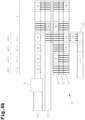
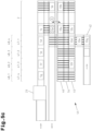
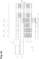
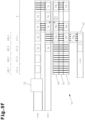
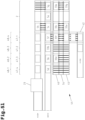
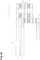
- the method additionally comprises steps m) to u). These steps are preceded by the processing of an order line for the first order, which, for example, comprises 2 pieces of product A, ( Fig. 6a-6b ) and the processing of an order line for the second order, which includes, for example, 1 piece of product C, ( Fig. 6b-6c ). This applies to steps b) to l) as described above.
- the provision of the third source container 5c at the first removal location 27a and the provision of the fourth source container 5g at the second removal location 27b can essentially be carried out in parallel or staggered manner.
- the process steps m) to u) concern further processing of the first order with a next order line and/or second order with a next order line and another measure in the provision of the first target container 33a and/or second target container 33a.
- Step n) is to be understood as meaning that the first target container 33a..33g and/or second target container 33a..33g remains stationary at the first loading station 34a/second loading station 34b until, preferably, all order lines for the first order and/or all order lines for the second order have been (completely) processed.
- the first source container 5a..5h and/or second source containers 5a..5h are provided in a corresponding sequence at the first removal station 24a and/or second removal station 24b, depending on the first target container 33a..33g and/or second target container 33a..33g to be processed.
- step r is carried out after the (complete) processing of the order line for the first order and during the movement of the robot 60 / the gripping unit 61 from the first target container 33a to the fourth source container 5g.
- the robot controller 64 receives the gripping surface pose of a gripping surface 63 for at least one of the goods G in the fourth source container 5g from the sensor system 62b, preferably shortly before the robot 60 / the gripping unit 61 has reached the fourth source container 5g.
- Step o) is carried out after the (complete) processing of the order line for the second order during the movement of the robot 60 / the gripping unit 61 from the second target container 33c to the third source container 5h.
- the robot controller 64 receives from the sensor system 62a, preferably shortly before the robot 60/the gripping unit 61 has reached the third source container 5h, the gripping surface pose of a gripping surface 63 for at least one of the goods H in the third source container 5a.
- the third source container 5h and/or fourth source container 5g are returned to a storage area 1 independently of one another after the picking of the goods H, G in accordance with steps p) and q) and/or steps s) and t), provided that goods H, G remain in the third source container 5h and/or fourth source container 5g after the removal of the goods.
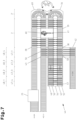
- Fig. 7 shows a possible combination of the above-described picking station 2 with robot 60 for automatic picking and a picking station 2' with manual picking with an operator.
- a picking station 2' with manual picking is shown in the WO 2018/006112 A1 described.
- the same structure of the delivery device 69 for source containers and the same structure of the delivery device for target containers 70 can be used.
- the delivery device 69 preferably has a single removal location for a source container, and the delivery device 70 preferably has a single loading location for a target container.
- Such a design allows those goods that can only be manipulated (picked) with difficulty or not at all by the robot 60 / gripping unit 61 to be processed with manual picking at the picking station 2'.
- the source container conveyor system of the picking station 2 is connected to the delivery device 69 by means of conveyor technology. and the target container conveyor of the picking station 2 is connected to the delivery device 70.
- the source containers containing such goods can be provided at the delivery device 69.
- the target containers loaded with such goods can be provided at the delivery device 70.
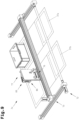
- FIG. 8 and 9 now show an exemplary picking station 2a with a fully automated robot system, which comprises a gantry robot 60a, in an oblique view, wherein the Fig. 8 the picking station 2a diagonally from the front and the Fig. 9 the picking station 2a is shown diagonally from behind.
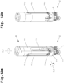
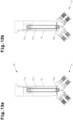
- Fig. 10 and 11 show the gantry robot 60a from the Fig. 8 and 9 with gripping unit 61 extended downwards, also in an oblique view.
- Fig. 10 shows the gantry robot 60a diagonally from the front and the Fig. 11 obliquely from behind.
- This gantry robot 60a can be used at the above-described picking station 2.
- this gantry robot 60a can be used to carry out the above-described methods for the fully automated picking of various goods from source containers 5a..5h into target containers 33a..33g (see also claims 16 to 25 or claims 26 to 38).
- the picking station 2a comprises two picking stations 27a, 27b, which are part of a conveyor device 12 or can be connected to it, as well as two loading stations 37a, 37b, which are part of a conveyor device 13 or can be connected to it.
- a source container 5a is arranged at the picking station 27a.
- the picking station 27b is empty in this example, but a source container 5b could of course be arranged on it.
- the loading stations 37a, 37b are also empty in this example, but target containers 33a, 33b could be positioned on them.
- the picking station 2a comprises two picking stations 27a, 27b and two loading stations 37a, 37b.
- a different number of picking stations 27a, 27b and loading stations 37a, 37b is provided, for example only one picking station 27a and one loading station 37a or more than two picking stations 27a, 27b and loading stations 37a, 37b.
- the goods A..H to be picked are provided directly (i.e. without source containers 5a, 5b and target containers 33a, 33b) at the picking stations 27a, 27b and loading stations 37a, 37b.
- the conveying device 12 is part of a source container conveying system for the automated transport of source containers 5a, 5b. Furthermore, the conveying device 13 is part of a target container conveying system for the automated transport of target containers 33a, 33b.
- the source container conveying system and/or the target container conveying system can be designed in particular as shown in one of the preceding figures. Accordingly, the source container conveying system can have a first supply device 24a, which includes the first removal location 27a, and an optional second supply device 24b, which includes the second removal location 27b.
- the target container conveying system can further have a first supply device 34a, which includes the first loading location 37a, and a second supply device 34b, which includes the second loading location 37b.
- the source container conveyor system for the automated transport of source containers 5a, 5b and/or the target container conveyor system for the automated transport of target containers 33a, 33b can be configured according to the embodiments described above.
- the above-described storage plate 66a and/or storage plate 66b and/or storage plate 66c and/or storage plate 66d can be present.
- the gantry robot 60a comprises a base frame, which in this example comprises four vertical supports 71.
- the base frame could also have longitudinal beams (extending in the x-direction) and/or cross beams (extending in the y-direction) connected to the vertical supports 71. It would also be conceivable for the base frame to have several side walls instead of the vertical supports 71 or in addition thereto.
- the gantry robot 60a further comprises a first gantry carriage 74 which is displaceably mounted relative to the vertical uprights 71 of the base frame and is horizontally movable in a first direction x via a first drive device 72 along a first guide arrangement 73.
- the gantry robot 60a comprises a second gantry carriage 77 which is displaceably mounted on the first gantry carriage 74 and is horizontally movable in a second direction y running transversely to the first direction x via a second drive device 75 along a second guide arrangement 76.
- the gantry robot 60a comprises a third gantry carriage 80 which is displaceably mounted on the second gantry carriage 77 and is vertically movable in a third direction z via a third drive device 78 along a third guide arrangement 79.
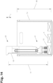
- the gantry robot 60a comprises a gripping unit 61 coupled to the third portal carriage 80 and rotatably mounted about a first axis of rotation Da1 and movable via a fourth drive device 81.
- the gantry robot 60a comprises a gantry arm 82 movable via the fourth drive device 81, which is rotatably mounted on the third gantry carriage 80 about a first, vertical axis of rotation Da1.
- the gripping unit 61 is rotatably mounted on the gantry arm 82 about a second, horizontal axis of rotation Da2 and is movable via a fifth drive device 83. Accordingly, the gripping unit 61 is rotatable both about the vertical axis of rotation Da1 and about the horizontal axis of rotation Da2.
Landscapes
- Engineering & Computer Science (AREA)
- Mechanical Engineering (AREA)
- Robotics (AREA)
- Warehouses Or Storage Devices (AREA)
- Specific Conveyance Elements (AREA)
- Manipulator (AREA)
Claims (6)
- Poste de préparation de commandes (2a) pour prélever des marchandises (A..H) dans des récipients sources (5a, 5b) et les placer dans des récipients cibles (33a, 33b), comprenantun système de convoyage de récipients sources pour le transport automatisé de récipients sources (5a, 5b) avec un premier dispositif de mise à disposition (24a) qui présente au moins un emplacement de prélèvement (27a) sur lequel un récipient source (5a, 5b) est mis à disposition,un système de convoyage de récipients cibles pour le transport automatisé de récipients cibles (33a, 33b) avec un premier dispositif de mise à disposition (34a) qui présente au moins un emplacement de chargement (37a) où un récipient cible (33a, 33b) est mis à disposition, etun système robotisé entièrement automatisé avec un robot portique (60a) et un système de capteurs (62a, 62b), en particulier un système de caméras, au moins pour détecter les marchandises (A..H) dans le récipient source (5a, 5b) et une commande de robot (64) qui est reliée au système de capteurs (62a, 62b) et commande le robot portique (60a) avec une unité de préhension (61), le robot portique (60a) comprenant un châssis de base (71),un premier chariot portique (74) monté de manière coulissante par rapport au châssis de base (71) et pouvant être déplacé horizontalement dans une première direction (x) le long d'un premier dispositif de guidage (73) via un premier dispositif d'entraînement (72),caractérisé en ce que en ce que le robot portique (60a) comprend en outre :un deuxième chariot portique (77) monté de manière coulissante sur le premier chariot portique (74) et pouvant être déplacé horizontalement dans une deuxième direction (y) perpendiculaire à la première direction (x) via un deuxième dispositif d'entraînement (75) le long d'un deuxième dispositif de guidage (76),un troisième chariot portique (80) monté de manière coulissante sur le deuxième chariot portique (77) et pouvant être déplacé verticalement dans une troisième direction (z) via un troisième dispositif d'entraînement (78) le long d'un troisième dispositif de guidage (79),un bras portique (82) monté de manière rotative sur le troisième chariot portique (80) autour d'un premier axe de rotation vertical (Da1) et mobile via un quatrième dispositif d'entraînement (81), etun logement de préhension (120) monté de manière rotative sur le bras portique (82) autour d'un deuxième axe de rotation horizontal (Da2) et mobile via un cinquième dispositif d'entraînement (83),l'unité de préhension (61) étant fixée au logement de préhension (120) et comprenant une ventouse à vide (117) qui forme une surface de préhension.
- Poste de préparation de commandes (2a) selon la revendication 1, caractérisé en ce que le bras portique (82) présente une paroi latérale décalée par rapport à un contour de section transversale maximal, qui s'étend de l'extrémité inférieure vers l'extrémité supérieure et forme une surface de délimitation (119) essentiellement plane.
- Poste de préparation de commandes (2a) selon la revendication 1 ou 2, caractérisé par un récipient source (5a, 5b) agencé sur au moins un emplacement de prélèvement (27a) et/ou un récipient cible (33a, 33b) agencé sur au moins un emplacement de chargement (37a), une hauteur d'immersion (ht), mesurée entre l'extrémité supérieure d'une surface de délimitation verticale (119) essentiellement plane du bras portique (82) et l'extrémité inférieure de l'unité de préhension (61), étant supérieure à 1,1 fois la hauteur de récipient (hB) du récipient source (5a, 5b) et/ou du récipient cible (33a, 33b).
- Poste de préparation de commandes (2a) selon la revendication 1, caractérisé par au moins un entraînement de récipientpour faire tourner l'au moins un emplacement de prélèvement (27a) et l'au moins un emplacement de chargement (37a) par rapport au châssis de base (71) du robot portique (60a) autour d'un axe de rotation vertical, et/oupour faire basculer le ou les emplacements de prélèvement (27a) et le ou les emplacements de chargement (37a) par rapport au châssis de base (71) du robot portique (60a) autour d'un axe de rotation horizontal.
- Poste de préparation de commandes (2a) selon la revendication 1, caractérisé en ce que le système de transport des récipients sources présente en outre un deuxième dispositif de mise à disposition (24b) qui comprend un emplacement de prélèvement (27b), et
le système de transport des récipients cibles présente en outre un deuxième dispositif de mise à disposition (34b) qui comprend un emplacement de chargement (37b). - Poste de préparation de commandes (2a) selon la revendication 5, caractérisé en ce que le système de transport des récipients sources comprendun premier convoyeur (25) pour acheminer les récipients sources (5a, 5b),un deuxième convoyeur (26) pour évacuer les récipients sources (5a, 5b) du premier dispositif de mise à disposition (24a) et du deuxième dispositif de mise à disposition (24b),un premier dispositif de transfert (28) pour transporter un premier récipient source (5a) depuis le premier convoyeur (25) vers le premier dispositif de mise à disposition (24a), etun deuxième dispositif de transfert (29) pour transporter un deuxième récipient source (5b) du premier convoyeur (25) vers le deuxième dispositif de mise à disposition (24b), le premier dispositif de mise à disposition (24a) avec le premier emplacement de prélèvement (27a) où le premier récipient source (5a) est mis à disposition étant relié, via le premier dispositif de transfert (28), au premier convoyeur (25) par un système de convoyage,le deuxième dispositif de mise à disposition (24b) avec le deuxième emplacement de prélèvement (27b) où le deuxième récipient source (5b) est mis à disposition étant relié, via le deuxième dispositif de transfert (29), au premier convoyeur (25) par un système de convoyage, etle premier dispositif de mise à disposition (24a) avec le premier emplacement de prélèvement (27a) et le deuxième dispositif de mise à disposition (24b) avec le deuxième emplacement de prélèvement (27b) étant agencés le long du deuxième convoyeur (26) pour évacuer les récipients sources (5a, 5b) et/ou le système de transport de récipients cibles comprendun premier convoyeur (35) pour évacuer les récipients cibles (33a, 33b),un deuxième convoyeur (36) pour évacuer les récipients cibles (33a, 33b) du premier dispositif de mise à disposition (34a) et du deuxième dispositif de mise à disposition (34b),un premier dispositif de transfert (38) pour transporter un premier récipient cible (33a) depuis le premier convoyeur (35) vers le premier dispositif de mise à disposition (34a), etun deuxième dispositif de transfert (39) pour transporter un deuxième récipient cible (33b) depuis le premier convoyeur (35) vers le deuxième dispositif de mise à disposition (34b),le premier dispositif de mise à disposition (34a) avec le premier emplacement de chargement (37a) où le premier récipient cible (33a) est mis à disposition étant relié, via le premier dispositif de transfert (38), au premier convoyeur (35) par un système de convoyage,le deuxième dispositif de mise à disposition (34b) avec la deuxième zone de chargement (37b) où est mis à disposition le deuxième récipient cible (33b) étant relié, via le deuxième dispositif de transfert (39), au premier convoyeur (35) via un système de convoyage etle premier dispositif de mise à disposition (34a) avec le premier emplacement de chargement (37a) et le deuxième dispositif de mise à disposition (34b) avec le deuxième emplacement de chargement (37b) étant agencés le long du deuxième convoyeur (36) pour évacuer les récipients cibles (33a, 33b),le premier dispositif de mise à disposition (24a) avec le premier emplacement de prélèvement (27a) et le premier dispositif de mise à disposition (34a) avec le premier emplacement de chargement (37a) étant situés l'un en face de l'autre,le deuxième dispositif de mise à disposition (24b) avec le deuxième emplacement de prélèvement (27b) et le deuxième dispositif de mise à disposition (34b) avec le deuxième emplacement de chargement (37b) étant agencés l'un en face de l'autre et le deuxième convoyeur (26) pour évacuer les récipients sources (5a, 5b) et le deuxième convoyeur (36) pour évacuer les récipients cible (33a, 33b) étant agencés en parallèle l'un avec l'autre.
Applications Claiming Priority (5)
| Application Number | Priority Date | Filing Date | Title |
|---|---|---|---|
| ATA50207/2018A AT520945A1 (de) | 2018-03-09 | 2018-03-09 | Kommissionierstation und Verfahren zum automatischen Kommissionieren von Waren |
| ATA50217/2018A AT520973A1 (de) | 2018-03-09 | 2018-03-13 | Kommissionierstation und Verfahren zum automatischen Kommissionieren von Waren |
| ATA50886/2018A AT520959A2 (de) | 2018-03-09 | 2018-10-10 | Kommissionierstation und Verfahren zum automatischen Kommissionieren von Waren |
| PCT/AT2019/060077 WO2019169419A2 (fr) | 2018-03-09 | 2019-03-07 | Station de préparation de commandes et procédé destiné à préparer automatiquement des commandes de marchandises |
| EP19718228.0A EP3762319B1 (fr) | 2018-03-09 | 2019-03-07 | Station de préparation de commandes et procédé destiné à préparer automatiquement des commandes de marchandises |
Related Parent Applications (2)
| Application Number | Title | Priority Date | Filing Date |
|---|---|---|---|
| EP19718228.0A Division-Into EP3762319B1 (fr) | 2018-03-09 | 2019-03-07 | Station de préparation de commandes et procédé destiné à préparer automatiquement des commandes de marchandises |
| EP19718228.0A Division EP3762319B1 (fr) | 2018-03-09 | 2019-03-07 | Station de préparation de commandes et procédé destiné à préparer automatiquement des commandes de marchandises |
Publications (3)
| Publication Number | Publication Date |
|---|---|
| EP4201852A1 EP4201852A1 (fr) | 2023-06-28 |
| EP4201852B1 true EP4201852B1 (fr) | 2025-07-02 |
| EP4201852C0 EP4201852C0 (fr) | 2025-07-02 |
Family
ID=67874555
Family Applications (4)
| Application Number | Title | Priority Date | Filing Date |
|---|---|---|---|
| EP23154647.4A Active EP4201852B1 (fr) | 2018-03-09 | 2019-03-07 | Poste de préparation de commandes et procédé automatique de commandes de marchandises |
| EP23154646.6A Active EP4194376B1 (fr) | 2018-03-09 | 2019-03-07 | Procédé de préparation automatique de commandes de marchandises |
| EP24208756.7A Pending EP4474318A3 (fr) | 2018-03-09 | 2019-03-07 | Procédé de préparation automatique de commandes de marchandises |
| EP19718228.0A Active EP3762319B1 (fr) | 2018-03-09 | 2019-03-07 | Station de préparation de commandes et procédé destiné à préparer automatiquement des commandes de marchandises |
Family Applications After (3)
| Application Number | Title | Priority Date | Filing Date |
|---|---|---|---|
| EP23154646.6A Active EP4194376B1 (fr) | 2018-03-09 | 2019-03-07 | Procédé de préparation automatique de commandes de marchandises |
| EP24208756.7A Pending EP4474318A3 (fr) | 2018-03-09 | 2019-03-07 | Procédé de préparation automatique de commandes de marchandises |
| EP19718228.0A Active EP3762319B1 (fr) | 2018-03-09 | 2019-03-07 | Station de préparation de commandes et procédé destiné à préparer automatiquement des commandes de marchandises |
Country Status (7)
| Country | Link |
|---|---|
| US (2) | US12098037B2 (fr) |
| EP (4) | EP4201852B1 (fr) |
| AT (4) | AT520945A1 (fr) |
| CA (1) | CA3093312A1 (fr) |
| DE (1) | DE112019001217A5 (fr) |
| ES (3) | ES3040271T3 (fr) |
| WO (1) | WO2019169419A2 (fr) |
Families Citing this family (15)
| Publication number | Priority date | Publication date | Assignee | Title |
|---|---|---|---|---|
| CN112405570A (zh) | 2019-08-21 | 2021-02-26 | 牧今科技 | 用于夹持和保持物体的机器人多夹持器组件和方法 |
| US11345029B2 (en) | 2019-08-21 | 2022-05-31 | Mujin, Inc. | Robotic multi-gripper assemblies and methods for gripping and holding objects |
| AT522891B1 (de) | 2019-08-22 | 2021-03-15 | Tgw Logistics Group Gmbh | Transport- und Manipulationssystem und Verfahren zum Transport von Ladungsträgern |
| PL3808685T3 (pl) * | 2019-10-16 | 2025-05-12 | Apo.Com Group Gmbh | Urządzenie i sposób sortowania i komisjonowania artykułów |
| AT524101A1 (de) * | 2020-07-27 | 2022-02-15 | Tgw Logistics Group Gmbh | System und Verfahren zur Erfassung einer Warenanzahl in einem Ladungsträger |
| GB202012459D0 (en) * | 2020-08-11 | 2020-09-23 | Ocado Innovation Ltd | A selector for robot-retrievable items |
| NO346957B1 (en) * | 2021-08-27 | 2023-03-20 | Autostore Tech As | A gripper assembly |
| AT525778B1 (de) * | 2021-11-09 | 2023-11-15 | Tgw Logistics Group Gmbh | Verfahren und Vorrichtung zum Entnehmen eines Ladeguts von einem Stapel |
| EP4258195A1 (fr) * | 2022-04-07 | 2023-10-11 | TGW Logistics Group GmbH | Optimisation de la fourniture de la marchandise à charger à un poste de préparation de commandes d'un système intralogistique |
| TW202413237A (zh) * | 2022-07-29 | 2024-04-01 | 日商遠程連接股份有限公司 | 商品移動裝置、商品移動裝置之控制方法及電腦程式 |
| AT526766A1 (de) * | 2022-12-09 | 2024-06-15 | Tgw Logistics Group Gmbh | Transfervorrichtung und Verfahren zum Umladen von Ware |
| US12370698B2 (en) | 2023-01-14 | 2025-07-29 | Sarcos Corp. | Robotic article handling end effector with capture device having a compliant diaphragm |
| US20250091822A1 (en) * | 2023-09-15 | 2025-03-20 | Material Handling Systems, Inc. | Conveyor subsystem for handling unconveyable parcels and parcel transfer system including same |
| DE102024113427B4 (de) | 2024-05-14 | 2026-05-13 | Ssi Schäfer Automation Gmbh | Maverick-Bündelung |
| FR3166374A1 (fr) * | 2024-09-19 | 2026-03-20 | Fives Xcella | Systeme de preparation de commandes |
Family Cites Families (79)
| Publication number | Priority date | Publication date | Assignee | Title |
|---|---|---|---|---|
| JPS5259475A (en) * | 1975-11-07 | 1977-05-16 | Hitachi Ltd | Palletizer for mixed transportation |
| FR2396709A1 (fr) * | 1977-07-08 | 1979-02-02 | Thibault Jacques | Appareil de palettisation |
| JPS5542991A (en) | 1978-09-22 | 1980-03-26 | Pechiyorusukii Gni I Puroekuto | Method of recovering petroleum by thermal mining |
| JPH0639387U (ja) | 1992-10-31 | 1994-05-24 | 株式会社イナックス | タンク製品の持上装置 |
| DE4407324C2 (de) | 1993-03-24 | 1996-05-09 | Bat Cigarettenfab Gmbh | Robotarm eines Flächenportalroboters |
| EP0616874B1 (fr) * | 1993-03-24 | 1997-09-10 | Hauni Maschinenbau Aktiengesellschaft | Bras de robot pour robot à portique |
| IT1263434B (it) * | 1993-06-16 | 1996-08-05 | Gd Spa | Unita' di prelievo ed alimentazione di pile di sbozzati |
| JP2004524595A (ja) | 2000-05-23 | 2004-08-12 | モンロー,チャーノマス | 物品取扱い装置において物品識別を含むための方法および装置 |
| US6681151B1 (en) | 2000-12-15 | 2004-01-20 | Cognex Technology And Investment Corporation | System and method for servoing robots based upon workpieces with fiducial marks using machine vision |
| JP3801498B2 (ja) * | 2001-12-17 | 2006-07-26 | 有限会社誠和工業 | 真空吸着パッドセッティング装置 |
| DE10352279A1 (de) | 2003-11-08 | 2005-06-09 | Kuka Roboter Gmbh | Verfahren und Vorrichtung zum Handhaben von Objekten |
| NO322426B1 (no) * | 2004-12-15 | 2006-10-02 | Optimar Giske As | Palleteringssystem |
| US7559737B2 (en) | 2005-01-14 | 2009-07-14 | Sentry Equipment Erectors Inc. | Vertically staggered pallet stacking assembly line and method |
| US8276739B2 (en) | 2007-01-25 | 2012-10-02 | Bastian Material Handling, Llc | Three-dimensional automated pick module |
| DE102007005534A1 (de) | 2007-02-03 | 2008-08-07 | Volkswagen Ag | Verfahren zur Steuerung der Position von verstellbaren Spann- und/oder Auflageelementen |
| DE102008006956B3 (de) | 2008-01-31 | 2009-09-03 | Grenzebach Maschinenbau Gmbh | Portalumsetzer für großflächige Glasplatten |
| US7967354B2 (en) | 2008-05-06 | 2011-06-28 | Fanuc Robotics America, Inc. | Mixed size product handling end of arm tool |
| DE102008046325A1 (de) | 2008-08-29 | 2010-03-11 | SSI Schäfer PEEM GmbH | Verfahren und Vorrichtung zum mannlosen, vollautomatisierten Kommissionieren von Artikeln in Auftragsladehilfsmittel |
| DE102009011294B4 (de) | 2009-03-02 | 2020-12-24 | Kuka Roboter Gmbh | Palletieren von Paketen mittels eines Manipulators |
| JP2013512513A (ja) | 2009-11-25 | 2013-04-11 | トッド・ジョセフ・ピアトニック | 製品送達システムのための制御システム及び制御方法 |
| CN201711969U (zh) | 2010-07-09 | 2011-01-19 | 华南理工大学 | 一种自带真空源的负压吸附模块 |
| AT511558B1 (de) | 2011-05-30 | 2013-04-15 | Knapp Ag | Knickarmgreifer |
| US8868231B2 (en) | 2011-08-10 | 2014-10-21 | Xerox Corporation | Flexible production collating system |
| AT511867A1 (de) | 2011-09-05 | 2013-03-15 | Tgw Mechanics Gmbh | Kommissionierstation und verfahren zum kommissionieren von artikeln aus ladehilfsmitteln |
| AT512339B1 (de) | 2011-12-21 | 2015-10-15 | Tgw Logistics Group Gmbh | Regallagersystem und verfahren zum betreiben desselben |
| US9486926B2 (en) | 2012-02-21 | 2016-11-08 | Amazon Technologies, Inc. | System and method for automatic picking of products in a materials handling facility |
| NL2008631C2 (nl) * | 2012-04-12 | 2013-10-16 | Vanderlande Ind Bv | Werkwijze en inrichting voor het vanuit producthouders volgens orders in verzamelhouders verzamelen van producten. |
| CN202640363U (zh) | 2012-06-04 | 2013-01-02 | 浙江好亚能源股份有限公司 | 一种输送硅片的吸盘装置 |
| US9064920B2 (en) | 2012-07-22 | 2015-06-23 | Varian Semiconductor Equipment Associates, Inc. | Electrostatic charge removal for solar cell grippers |
| JP6172293B2 (ja) | 2013-01-20 | 2017-08-02 | 株式会社ダイフク | トレーラやコンテナから製品を荷下し/荷解きするための自動トラック荷下し装置 |
| DE102013202247A1 (de) | 2013-02-12 | 2014-08-14 | Krones Aktiengesellschaft | Verfahren zur Störungsmeldung bei der Gruppierung von Artikeln |
| US9481518B2 (en) * | 2013-02-24 | 2016-11-01 | Intelligrated Headquarters Llc | Order fulfillment system and method |
| JP5768827B2 (ja) | 2013-03-14 | 2015-08-26 | 株式会社安川電機 | ロボットシステムおよびワークの搬送方法 |
| AT514162A1 (de) | 2013-04-09 | 2014-10-15 | Knapp Ag | Lager- und Kommissioniersystem zum vollautomatisierten Erkennen und Kommissionieren von Artikeln |
| GB201402263D0 (en) * | 2014-02-10 | 2014-03-26 | Ocado Ltd | Intermediate holding facility for picking station |
| NL2012528B1 (nl) | 2014-03-28 | 2016-02-15 | Vanderlande Ind Bv | Systeem voor het verzamelen van producten alsmede werkwijze voor toepassing daarvan. |
| FR3020303B1 (fr) | 2014-04-25 | 2016-07-15 | Sileane | Procede et installation de prehension automatique d'un objet. |
| US20150314439A1 (en) | 2014-05-02 | 2015-11-05 | Precision Machinery Research & Development Center | End effector controlling method |
| MX385504B (es) | 2014-07-11 | 2025-03-18 | Dematic Corp | Estacion de seleccion con almacen automatizado. |
| US9205558B1 (en) | 2014-07-16 | 2015-12-08 | Google Inc. | Multiple suction cup control |
| US9272417B2 (en) | 2014-07-16 | 2016-03-01 | Google Inc. | Real-time determination of object metrics for trajectory planning |
| US9457477B1 (en) | 2014-08-25 | 2016-10-04 | Google Inc. | Variable stiffness suction gripper |
| JP5893695B1 (ja) | 2014-09-10 | 2016-03-23 | ファナック株式会社 | 物品搬送システム |
| US9381645B1 (en) | 2014-12-08 | 2016-07-05 | Amazon Technologies, Inc. | System for automating manipulation of items |
| US9561587B2 (en) | 2014-12-16 | 2017-02-07 | Amazon Technologies, Inc. | Robotic grasping of items in inventory system |
| JP6486114B2 (ja) | 2015-01-16 | 2019-03-20 | 株式会社東芝 | 荷役装置 |
| US9656806B2 (en) | 2015-02-13 | 2017-05-23 | Amazon Technologies, Inc. | Modular, multi-function smart storage containers |
| EP3261809B1 (fr) * | 2015-02-25 | 2022-09-21 | Dematic Corp. | Système et procédé de traitement de commande automatisés |
| KR20160120373A (ko) | 2015-04-07 | 2016-10-18 | 삼성중공업 주식회사 | 연료가스 공급시스템 |
| US9327397B1 (en) | 2015-04-09 | 2016-05-03 | Codeshelf | Telepresence based inventory pick and place operations through robotic arms affixed to each row of a shelf |
| DE102015007863A1 (de) | 2015-06-18 | 2015-12-10 | Daimler Ag | Verfahren und Vorrichtung zum Positionieren eines Bauteils, insbesondere zur Herstellung eines Fahrzeugs |
| NL2015044B1 (nl) | 2015-06-29 | 2017-01-24 | Stichting Sangria | Systeem en werkwijze voor het opslaan van voorwerpen. |
| US10023393B2 (en) | 2015-09-29 | 2018-07-17 | Amazon Technologies, Inc. | Robotic tossing of items in inventory system |
| US9926138B1 (en) | 2015-09-29 | 2018-03-27 | Amazon Technologies, Inc. | Determination of removal strategies |
| JP2017100214A (ja) | 2015-11-30 | 2017-06-08 | 株式会社リコー | マニピュレータシステム、撮像システム、対象物の受け渡し方法、及び、マニピュレータ制御プログラム |
| CA3178222C (fr) * | 2015-12-04 | 2026-04-21 | Berkshire Grey Operating Company, Inc. | Systemes et procedes permettant un traitement dynamique d'objets |
| US9751693B1 (en) * | 2016-02-01 | 2017-09-05 | Amazon Technologies, Inc. | Automated shipment set item consolidation |
| WO2017143367A1 (fr) | 2016-02-26 | 2017-08-31 | Knapp Ag | Système d'entreposage et de préparation de commandes partiellement automatique |
| CN205552559U (zh) | 2016-03-28 | 2016-09-07 | 苏州倍特罗智能科技有限公司 | 一种三吸盘结构 |
| US20170322561A1 (en) | 2016-05-03 | 2017-11-09 | Bby Solutions, Inc. | Robotic inventory dispensary operational enhancements |
| US9827677B1 (en) | 2016-05-16 | 2017-11-28 | X Development Llc | Robotic device with coordinated sweeping tool and shovel tool |
| EP3445680A1 (fr) | 2016-05-17 | 2019-02-27 | Liebherr-Verzahntechnik GmbH | Cellule de préparation des commandes |
| ITUA20163824A1 (it) * | 2016-05-26 | 2017-11-26 | Granitifiandre Spa | Apparecchiatura per smistare oggetti |
| EP3263292B1 (fr) | 2016-06-28 | 2025-07-16 | Tata Consultancy Services Limited | Dispositif de préhension adaptatif |
| DE102016008078A1 (de) | 2016-06-30 | 2018-01-04 | Servus Intralogistics Gmbh | Schienengebundener Transportroboter zur Kommissionierung von Waren im Lagerregal und Verfahren zu dessen Betrieb |
| AT518818B1 (de) * | 2016-07-08 | 2018-06-15 | Tgw Logistics Group Gmbh | Verfahren zum Kommissionieren von Artikeln und Kommissionierstation |
| JP2018015815A (ja) | 2016-07-25 | 2018-02-01 | 株式会社村上製作所 | 移送装置及びワーク吸着装置 |
| US10108194B1 (en) | 2016-09-02 | 2018-10-23 | X Development Llc | Object placement verification |
| CN206066477U (zh) | 2016-09-28 | 2017-04-05 | 吉首大学 | 一种用于转移曲面玻璃板的机械臂 |
| US11312571B2 (en) | 2017-01-17 | 2022-04-26 | Amazon Technologies, Inc. | Stackable inventory storage modules, storage systems, and methods of using the same |
| AT519452B1 (de) | 2017-01-18 | 2018-07-15 | Tgw Logistics Group Gmbh | Verfahren und Vorrichtung zum Kommissionieren von Waren |
| US11514386B1 (en) | 2017-03-01 | 2022-11-29 | Blue Yonder Group, Inc. | System and method of displaying layout-based instructions using augmented reality |
| JP6438512B2 (ja) | 2017-03-13 | 2018-12-12 | ファナック株式会社 | 機械学習により補正した計測データでワークの取り出しを行うロボットシステム、計測データ処理装置および計測データ処理方法 |
| US10586418B2 (en) | 2017-09-29 | 2020-03-10 | Omnicell, Inc. | Apparatuses, systems, and methods for the automated dispensing of articles |
| US10926408B1 (en) | 2018-01-12 | 2021-02-23 | Amazon Technologies, Inc. | Artificial intelligence system for efficiently learning robotic control policies |
| US10773839B1 (en) | 2018-02-08 | 2020-09-15 | Amazon Technologies, Inc. | Methods for packaging items and preparing packaging materials |
| US10843333B2 (en) * | 2018-03-05 | 2020-11-24 | Berkshire Grey, Inc. | Systems and methods for processing objects, including automated re-circulating processing stations |
| JP7145702B2 (ja) * | 2018-09-07 | 2022-10-03 | 株式会社日立物流 | ロボットシステム及びその制御方法 |
| US10549928B1 (en) | 2019-02-22 | 2020-02-04 | Dexterity, Inc. | Robotic multi-item type palletizing and depalletizing |
-
2018
- 2018-03-09 AT ATA50207/2018A patent/AT520945A1/de not_active Application Discontinuation
- 2018-03-13 AT ATA50217/2018A patent/AT520973A1/de not_active Application Discontinuation
- 2018-10-10 AT ATA50886/2018A patent/AT520959A2/de not_active Application Discontinuation
-
2019
- 2019-03-07 ES ES23154647T patent/ES3040271T3/es active Active
- 2019-03-07 CA CA3093312A patent/CA3093312A1/fr active Pending
- 2019-03-07 ES ES23154646T patent/ES3023457T3/es active Active
- 2019-03-07 EP EP23154647.4A patent/EP4201852B1/fr active Active
- 2019-03-07 WO PCT/AT2019/060077 patent/WO2019169419A2/fr not_active Ceased
- 2019-03-07 DE DE112019001217.7T patent/DE112019001217A5/de active Pending
- 2019-03-07 US US16/978,305 patent/US12098037B2/en active Active
- 2019-03-07 EP EP23154646.6A patent/EP4194376B1/fr active Active
- 2019-03-07 AT ATA9085/2019A patent/AT523873B1/de active
- 2019-03-07 ES ES19718228T patent/ES2955509T3/es active Active
- 2019-03-07 EP EP24208756.7A patent/EP4474318A3/fr active Pending
- 2019-03-07 EP EP19718228.0A patent/EP3762319B1/fr active Active
-
2024
- 2024-07-25 US US18/783,828 patent/US20240375889A1/en active Pending
Also Published As
| Publication number | Publication date |
|---|---|
| EP4194376B1 (fr) | 2025-01-29 |
| WO2019169419A2 (fr) | 2019-09-12 |
| ES3040271T3 (en) | 2025-10-29 |
| US20210024298A1 (en) | 2021-01-28 |
| CA3093312A1 (fr) | 2019-09-12 |
| US12098037B2 (en) | 2024-09-24 |
| WO2019169419A3 (fr) | 2019-10-31 |
| EP3762319B1 (fr) | 2023-06-07 |
| EP3762319C0 (fr) | 2023-06-07 |
| EP4201852A1 (fr) | 2023-06-28 |
| DE112019001217A5 (de) | 2021-02-18 |
| AT523873B1 (de) | 2022-03-15 |
| AT520973A1 (de) | 2019-09-15 |
| US20240375889A1 (en) | 2024-11-14 |
| EP4194376A1 (fr) | 2023-06-14 |
| EP4194376C0 (fr) | 2025-01-29 |
| EP3762319A2 (fr) | 2021-01-13 |
| ES2955509T3 (es) | 2023-12-04 |
| EP4474318A2 (fr) | 2024-12-11 |
| AT520945A1 (de) | 2019-09-15 |
| ES3023457T3 (en) | 2025-06-02 |
| AT520959A2 (de) | 2019-09-15 |
| EP4201852C0 (fr) | 2025-07-02 |
| EP4474318A3 (fr) | 2025-03-12 |
| AT523873A5 (de) | 2021-11-15 |
Similar Documents
| Publication | Publication Date | Title |
|---|---|---|
| EP4194376B1 (fr) | Procédé de préparation automatique de commandes de marchandises | |
| EP2315714B1 (fr) | Dispositif entièrement automatique de préparation d'articles dans des contenants de commandes | |
| AT512338B1 (de) | Kommissionierstation und verfahren zum kommissionieren von artikeln | |
| EP1452462B1 (fr) | Système et procédé pour la préparation de commandes d'articles stockés dans des conteneurs | |
| EP2102063B1 (fr) | Chargement et déchargement de bagages aériens | |
| WO2018024311A1 (fr) | Système de préparation de commandes | |
| CH687522A5 (de) | Regalbediengeraet. | |
| EP3459880B1 (fr) | Système de préparation des commandes au moyen d'un bras robotisé articulé | |
| DE60101701T2 (de) | Verfahren und Vorrichtung zum überführen von Blisterverpackungen von einem auf einen anderen Bandförderer | |
| AT14071U1 (de) | Kommissionierstation und Verfahren zum Kommissionieren von Artikeln aus Ladehilfsmitteln | |
| AT13355U1 (de) | Verfahren zum Kommissionieren von Artikeln sowie dazu ausgebildete Kommissioniervorrichtung | |
| DE19812147A1 (de) | Kommissionieranlage mit Schnelldrehautomat und Regalbediengerät | |
| AT511860A2 (de) | Kommissionierstation und verfahren zum bereitstellen von ladehilfsmitteln | |
| EP4067266B1 (fr) | Poste de travail de préparation de commande et procédé de préparation de commande sur un poste de travail de préparation de commande | |
| DE102004025070B4 (de) | Verfahren und Vorrichtung zur Einlagerung von Waren in eine automatisierte Lagervorrichtung | |
| EP0256403B1 (fr) | Procédé de transfert automatique de muselets en fil métallique pour bouteilles à champagne d'une station d'usinage à un empilage ou d'un empilage à une station d'usinage ultérieure et dispositif pour la mise en oeuvre de ce procédé | |
| EP4701961A1 (fr) | Système de préparation de commandes et procédé de préparation de commandes de marchandises à la pièce | |
| DE102009014636B4 (de) | Kommissionierung von Schnittblumen und/oder Pflanzen mit einem Roboter | |
| DE102024123149A1 (de) | Inbound-system und verfahren zum aufnehmen zumindest eines artikels in ein lagersystem |
Legal Events
| Date | Code | Title | Description |
|---|---|---|---|
| PUAI | Public reference made under article 153(3) epc to a published international application that has entered the european phase |
Free format text: ORIGINAL CODE: 0009012 |
|
| STAA | Information on the status of an ep patent application or granted ep patent |
Free format text: STATUS: THE APPLICATION HAS BEEN PUBLISHED |
|
| AC | Divisional application: reference to earlier application |
Ref document number: 3762319 Country of ref document: EP Kind code of ref document: P |
|
| AK | Designated contracting states |
Kind code of ref document: A1 Designated state(s): AL AT BE BG CH CY CZ DE DK EE ES FI FR GB GR HR HU IE IS IT LI LT LU LV MC MK MT NL NO PL PT RO RS SE SI SK SM TR |
|
| P01 | Opt-out of the competence of the unified patent court (upc) registered |
Effective date: 20230629 |
|
| STAA | Information on the status of an ep patent application or granted ep patent |
Free format text: STATUS: REQUEST FOR EXAMINATION WAS MADE |
|
| 17P | Request for examination filed |
Effective date: 20231219 |
|
| RBV | Designated contracting states (corrected) |
Designated state(s): AL AT BE BG CH CY CZ DE DK EE ES FI FR GB GR HR HU IE IS IT LI LT LU LV MC MK MT NL NO PL PT RO RS SE SI SK SM TR |
|
| STAA | Information on the status of an ep patent application or granted ep patent |
Free format text: STATUS: EXAMINATION IS IN PROGRESS |
|
| 17Q | First examination report despatched |
Effective date: 20240422 |
|
| GRAP | Despatch of communication of intention to grant a patent |
Free format text: ORIGINAL CODE: EPIDOSNIGR1 |
|
| STAA | Information on the status of an ep patent application or granted ep patent |
Free format text: STATUS: GRANT OF PATENT IS INTENDED |
|
| INTG | Intention to grant announced |
Effective date: 20241205 |
|
| GRAJ | Information related to disapproval of communication of intention to grant by the applicant or resumption of examination proceedings by the epo deleted |
Free format text: ORIGINAL CODE: EPIDOSDIGR1 |
|
| STAA | Information on the status of an ep patent application or granted ep patent |
Free format text: STATUS: EXAMINATION IS IN PROGRESS |
|
| GRAP | Despatch of communication of intention to grant a patent |
Free format text: ORIGINAL CODE: EPIDOSNIGR1 |
|
| STAA | Information on the status of an ep patent application or granted ep patent |
Free format text: STATUS: GRANT OF PATENT IS INTENDED |
|
| RAP3 | Party data changed (applicant data changed or rights of an application transferred) |
Owner name: TGW HOLDING GMBH |
|
| INTC | Intention to grant announced (deleted) | ||
| GRAS | Grant fee paid |
Free format text: ORIGINAL CODE: EPIDOSNIGR3 |
|
| RAP1 | Party data changed (applicant data changed or rights of an application transferred) |
Owner name: TGW LOGISTICS GMBH |
|
| INTG | Intention to grant announced |
Effective date: 20250429 |
|
| GRAA | (expected) grant |
Free format text: ORIGINAL CODE: 0009210 |
|
| STAA | Information on the status of an ep patent application or granted ep patent |
Free format text: STATUS: THE PATENT HAS BEEN GRANTED |
|
| AC | Divisional application: reference to earlier application |
Ref document number: 3762319 Country of ref document: EP Kind code of ref document: P |
|
| AK | Designated contracting states |
Kind code of ref document: B1 Designated state(s): AL AT BE BG CH CY CZ DE DK EE ES FI FR GB GR HR HU IE IS IT LI LT LU LV MC MK MT NL NO PL PT RO RS SE SI SK SM TR |
|
| REG | Reference to a national code |
Ref country code: GB Ref legal event code: FG4D Free format text: NOT ENGLISH |
|
| REG | Reference to a national code |
Ref country code: CH Ref legal event code: EP |
|
| REG | Reference to a national code |
Ref country code: DE Ref legal event code: R096 Ref document number: 502019013578 Country of ref document: DE |
|
| REG | Reference to a national code |
Ref country code: IE Ref legal event code: FG4D Free format text: LANGUAGE OF EP DOCUMENT: GERMAN |
|
| U01 | Request for unitary effect filed |
Effective date: 20250724 |
|
| U07 | Unitary effect registered |
Designated state(s): AT BE BG DE DK EE FI FR IT LT LU LV MT NL PT RO SE SI Effective date: 20250731 |
|
| P04 | Withdrawal of opt-out of the competence of the unified patent court (upc) registered |
Free format text: CASE NUMBER: APP_541491_1/2023 Effective date: 20250731 |
|
| REG | Reference to a national code |
Ref country code: ES Ref legal event code: FG2A Ref document number: 3040271 Country of ref document: ES Kind code of ref document: T3 Effective date: 20251029 |
|
| PG25 | Lapsed in a contracting state [announced via postgrant information from national office to epo] |
Ref country code: IS Free format text: LAPSE BECAUSE OF FAILURE TO SUBMIT A TRANSLATION OF THE DESCRIPTION OR TO PAY THE FEE WITHIN THE PRESCRIBED TIME-LIMIT Effective date: 20251102 |
|
| PG25 | Lapsed in a contracting state [announced via postgrant information from national office to epo] |
Ref country code: NO Free format text: LAPSE BECAUSE OF FAILURE TO SUBMIT A TRANSLATION OF THE DESCRIPTION OR TO PAY THE FEE WITHIN THE PRESCRIBED TIME-LIMIT Effective date: 20251002 |
|
| PG25 | Lapsed in a contracting state [announced via postgrant information from national office to epo] |
Ref country code: HR Free format text: LAPSE BECAUSE OF FAILURE TO SUBMIT A TRANSLATION OF THE DESCRIPTION OR TO PAY THE FEE WITHIN THE PRESCRIBED TIME-LIMIT Effective date: 20250702 |
|
| PG25 | Lapsed in a contracting state [announced via postgrant information from national office to epo] |
Ref country code: GR Free format text: LAPSE BECAUSE OF FAILURE TO SUBMIT A TRANSLATION OF THE DESCRIPTION OR TO PAY THE FEE WITHIN THE PRESCRIBED TIME-LIMIT Effective date: 20251003 |
|
| PG25 | Lapsed in a contracting state [announced via postgrant information from national office to epo] |
Ref country code: CZ Free format text: LAPSE BECAUSE OF FAILURE TO SUBMIT A TRANSLATION OF THE DESCRIPTION OR TO PAY THE FEE WITHIN THE PRESCRIBED TIME-LIMIT Effective date: 20250702 |
|
| PG25 | Lapsed in a contracting state [announced via postgrant information from national office to epo] |
Ref country code: PL Free format text: LAPSE BECAUSE OF FAILURE TO SUBMIT A TRANSLATION OF THE DESCRIPTION OR TO PAY THE FEE WITHIN THE PRESCRIBED TIME-LIMIT Effective date: 20250702 |
|
| PG25 | Lapsed in a contracting state [announced via postgrant information from national office to epo] |
Ref country code: RS Free format text: LAPSE BECAUSE OF FAILURE TO SUBMIT A TRANSLATION OF THE DESCRIPTION OR TO PAY THE FEE WITHIN THE PRESCRIBED TIME-LIMIT Effective date: 20251002 |
|
| PG25 | Lapsed in a contracting state [announced via postgrant information from national office to epo] |
Ref country code: SM Free format text: LAPSE BECAUSE OF FAILURE TO SUBMIT A TRANSLATION OF THE DESCRIPTION OR TO PAY THE FEE WITHIN THE PRESCRIBED TIME-LIMIT Effective date: 20250702 |
|
| PGFP | Annual fee paid to national office [announced via postgrant information from national office to epo] |
Ref country code: GB Payment date: 20260324 Year of fee payment: 8 |
|
| U20 | Renewal fee for the european patent with unitary effect paid |
Year of fee payment: 8 Effective date: 20260306 |
|
| PG25 | Lapsed in a contracting state [announced via postgrant information from national office to epo] |
Ref country code: SK Free format text: LAPSE BECAUSE OF FAILURE TO SUBMIT A TRANSLATION OF THE DESCRIPTION OR TO PAY THE FEE WITHIN THE PRESCRIBED TIME-LIMIT Effective date: 20250702 |
|
| PLBE | No opposition filed within time limit |
Free format text: ORIGINAL CODE: 0009261 |
|
| STAA | Information on the status of an ep patent application or granted ep patent |
Free format text: STATUS: NO OPPOSITION FILED WITHIN TIME LIMIT |
|
| REG | Reference to a national code |
Ref country code: CH Ref legal event code: L10 Free format text: ST27 STATUS EVENT CODE: U-0-0-L10-L00 (AS PROVIDED BY THE NATIONAL OFFICE) Effective date: 20260518 |
|
| REG | Reference to a national code |
Ref country code: CH Ref legal event code: U11 Free format text: ST27 STATUS EVENT CODE: U-0-0-U10-U11 (AS PROVIDED BY THE NATIONAL OFFICE) Effective date: 20260528 |
|
| 26N | No opposition filed |
Effective date: 20260407 |
|
| PGFP | Annual fee paid to national office [announced via postgrant information from national office to epo] |
Ref country code: ES Payment date: 20260402 Year of fee payment: 8 |
|
| PGFP | Annual fee paid to national office [announced via postgrant information from national office to epo] |
Ref country code: CH Payment date: 20260528 Year of fee payment: 8 |