EP3855974B1 - Flasche mit einem roll-on-applikator und einem stopfen - Google Patents
Flasche mit einem roll-on-applikator und einem stopfen Download PDFInfo
- Publication number
- EP3855974B1 EP3855974B1 EP19790687.8A EP19790687A EP3855974B1 EP 3855974 B1 EP3855974 B1 EP 3855974B1 EP 19790687 A EP19790687 A EP 19790687A EP 3855974 B1 EP3855974 B1 EP 3855974B1
- Authority
- EP
- European Patent Office
- Prior art keywords
- ball
- bottle
- applicator
- reservoir
- holder
- Prior art date
- Legal status (The legal status is an assumption and is not a legal conclusion. Google has not performed a legal analysis and makes no representation as to the accuracy of the status listed.)
- Active
Links
Images



Classifications
-
- A—HUMAN NECESSITIES
- A45—HAND OR TRAVELLING ARTICLES
- A45D—HAIRDRESSING OR SHAVING EQUIPMENT; EQUIPMENT FOR COSMETICS OR COSMETIC TREATMENTS, e.g. FOR MANICURING OR PEDICURING
- A45D34/00—Containers or accessories specially adapted for handling liquid toiletry or cosmetic substances, e.g. perfumes
- A45D34/04—Appliances specially adapted for applying liquid, e.g. using roller or ball
- A45D34/041—Appliances specially adapted for applying liquid, e.g. using roller or ball using a roller, a disc or a ball
-
- A—HUMAN NECESSITIES
- A45—HAND OR TRAVELLING ARTICLES
- A45D—HAIRDRESSING OR SHAVING EQUIPMENT; EQUIPMENT FOR COSMETICS OR COSMETIC TREATMENTS, e.g. FOR MANICURING OR PEDICURING
- A45D40/00—Casings or accessories specially adapted for storing or handling solid or pasty toiletry or cosmetic substances, e.g. shaving soaps or lipsticks
- A45D40/22—Casings characterised by a hinged cover
-
- A—HUMAN NECESSITIES
- A45—HAND OR TRAVELLING ARTICLES
- A45D—HAIRDRESSING OR SHAVING EQUIPMENT; EQUIPMENT FOR COSMETICS OR COSMETIC TREATMENTS, e.g. FOR MANICURING OR PEDICURING
- A45D40/00—Casings or accessories specially adapted for storing or handling solid or pasty toiletry or cosmetic substances, e.g. shaving soaps or lipsticks
- A45D40/26—Appliances specially adapted for applying pasty paint, e.g. using roller, using a ball
- A45D40/261—Appliances specially adapted for applying pasty paint, e.g. using roller, using a ball using a ball, a roller or the like
-
- A—HUMAN NECESSITIES
- A45—HAND OR TRAVELLING ARTICLES
- A45D—HAIRDRESSING OR SHAVING EQUIPMENT; EQUIPMENT FOR COSMETICS OR COSMETIC TREATMENTS, e.g. FOR MANICURING OR PEDICURING
- A45D40/00—Casings or accessories specially adapted for storing or handling solid or pasty toiletry or cosmetic substances, e.g. shaving soaps or lipsticks
- A45D40/22—Casings characterised by a hinged cover
- A45D2040/225—Casings characterised by a hinged cover characterised by the opening or closing movement of the lid
-
- B—PERFORMING OPERATIONS; TRANSPORTING
- B05—SPRAYING OR ATOMISING IN GENERAL; APPLYING FLUENT MATERIALS TO SURFACES, IN GENERAL
- B05C—APPARATUS FOR APPLYING FLUENT MATERIALS TO SURFACES, IN GENERAL
- B05C17/00—Hand tools or apparatus using hand held tools, for applying liquids or other fluent materials to, for spreading applied liquids or other fluent materials on, or for partially removing applied liquids or other fluent materials from, surfaces
- B05C17/02—Rollers ; Hand tools comprising coating rollers or coating endless belts
- B05C17/0207—Rollers ; Hand tools comprising coating rollers or coating endless belts characterised by the cover, e.g. cover material or structure, special surface for producing patterns
Definitions
- the invention relates to the field of devices for dispensing and applying a perfume or a cosmetic, toiletry or care product. It relates in particular to roll-on dispensing and application devices, commonly called roll-on applicators, or, in English terminology, "roll-ons”.
- cosmetic products include, in particular, all products for applying makeup to the skin, lips, or appendages.
- Toiletries include shower gels, bath products, as well as body lotions and deodorants.
- Perfumes refer in particular to all perfuming or odorous compositions intended for bodily application.
- Care products include, in particular, products intended to be applied to the human or animal body to clean it, perfume it, change its appearance, or maintain it in good condition.
- Ball applicators are commonly used for dispensing and applying a liquid or semi-fluid product contained in a bottle equipped with such a dispenser.
- a bottle with a ball dispenser has a ball at its dispensing neck, included in a ball holder or cage.
- the ball holder has a dispensing orifice in communication with the interior of the bottle.
- the ball has a diameter greater than that of the dispensing orifice.
- the ball holder Opposite the dispensing orifice of the bottle, the ball holder has a mouth.
- the ball is held in the ball holder, for example by a radial enclosing lip oriented towards the axis of revolution of the ball holder.
- the ball is thus held in the ball holder, on the dispensing orifice, free to rotate.
- the product contained in the bottle reaches the ball and charges its visible surface in the dispensing orifice.
- Rotating the ball for example to apply the product to the skin, allows the wet surface of the ball to be placed opposite the dispensing orifice, in a position where it is visible and in contact with the application surface.
- Roll-on applicators are therefore simple devices that allow the simultaneous distribution and application of a liquid or semi-fluid product. However, they have certain drawbacks. They do not provide a perfect seal by themselves, particularly an airtight seal that is often necessary for the proper preservation of the product and/or to prevent its loss, particularly through evaporation. Indeed, the clearance required for the free rotation of the ball in the ball holder does not allow such a seal.
- the document US2912708 discloses a roll-on application device, in which an insert or orifice formed directly in the body of the device receives the roll-on. A seal in the form of a band covers the roll-on.
- the document US3055041 discloses a similar applicator that may include a rotating shutter.
- the document US8500355 discloses a massage device comprising a ball and a liquid dispenser comprising a ball holder and a spring interposed between the ball holder and the body of the dispenser.
- the invention thus aims to propose a bottle comprising a ball tip ensuring good sealing outside of the phases application of the product, and not having the aforementioned drawbacks of the devices known in the state of the art.
- the invention relates to a bottle comprising a reservoir having an interior volume adapted to contain a liquid or semi-fluid product and a dispensing head extending projecting from the reservoir along a main axis, said dispensing head comprising a ball applicator comprising a ball holder in which a ball is caged free to rotate and from which a cap of the ball emerges on the side opposite the reservoir.
- the bottle comprises a rotary shutter adapted to cover the ball applicator in a closed position of the bottle, and to be released from said ball applicator for dispensing the product in an open position of the bottle.
- the rotary shutter is movable in rotation relative to the rest of the bottle along an axis of rotation crossing perpendicularly said main axis.
- the ball applicator comprises an applicator body in which the ball holder is mounted in translation along the main axis, and in which an elastic means is interposed between the applicator body and the ball holder.
- the roll-on applicator comprises an elastic means and is configured so that the ball can translate together with the ball holder along the main axis to adopt a retracted position in the dispensing head when the roll-on applicator is capped by the rotary shutter in the closed position of the bottle, said elastic means being compressed, and to adopt a deployed position outside the dispensing head under the effect of a relaxation of the elastic means when the rotary shutter is disengaged from the roll-on applicator.
- the rotary shutter comprises a cap in which is arranged a shutter element comprising a concavity of a shape complementary to that of the cap of the ball projecting from the ball holder, and the shutter element bears on the upper face of the ball holder when the ball is engaged in the concavity.
- a rotating shutter thus linked to the rest of the bottle, for example to the reservoir or to the dispensing head (for example to a neck of the bottle), in line with the ball of the ball applicator, allows the desired seal to be obtained, without requiring the use of a bulky applicator.
- the shutter is more reliable than a clip-on cap, and is captive because it is linked to the rest of the bottle both when it is closed and open.
- a configuration in which the elastic means is interposed between an applicator body and the ball holder allows the use of a simple and reliable elastic means (for example a helical spring), which is not exposed to the product being dispensed; It also allows significant movement of the ball between the closed position of the bottle and its deployed position. This allows for a bottle that is both compact when closed and allows easy application of product when the ball is deployed.
- the ball holder may comprise a product supply conduit extending along the main axis towards the interior volume and the applicator body may comprise an upper volume separated from the interior volume of the reservoir by a partition comprising in its center a well which is closed in the lower part by a bottom, the walls of the well comprising at least one light, said bottle being configured so that when it is in the closed position the supply conduit closes said light and when it is in the open position said light is clear.
- the elastic means can for example be a helical spring.
- the sealing element may comprise a resilient element.
- the closure element may have chamfered edges parallel to the axis of rotation of the rotary shutter, the chamfers thus formed coming into contact with the ball when moving from the open position to the closed position.
- the tank may have an external shape of revolution, said axis of rotation of the rotary shutter being coincident with an axis of revolution of the external shape of the tank.
- the tank may in particular have an external shape of a cylinder whose height is less than or equal to its radius.
- FIG. 1 represents a bottle in accordance with a preferred, but not exclusive, embodiment of the invention.
- the bottle comprises a reservoir 1 capable of containing a liquid or semi-fluid product.
- the bottle which is the subject of the invention is in particular intended to contain a perfume or a cosmetic, toiletry or care product.
- the reservoir of the bottle which is the subject of the invention can thus have a capacity (internal volume intended to receive the product) of between 10 mL and 500 mL, in particular 20 mL, 35 mL, 75 mL, 100 mL, or 200 mL.
- the tank in the example shown here has a flattened cylindrical shape of revolution.
- the term flattened indicates that the cylinder has a disc shape, or a height H of small dimension compared to its diameter.
- the tank 1 has a thickness (corresponding to the height H of the cylinder which defines it) less than or equal to its radius r.
- the bottle further comprises a dispensing head 2.
- the dispensing head 2 is positioned on the edge of the reservoir 1 of the bottle shown here, that is to say on the side wall 3 of the cylindrical reservoir 1 from which it projects.
- the dispensing head 2 comprises a neck 4 in which a ball applicator 5 is assembled.
- the dispensing head extends in a general direction of extension which materializes a main axis A of the bottle.
- the bottle which is the subject of the invention comprises a rotary shutter 6, i.e. one which can rotate relative to the rest of the bottle, and the operation of which is described in more detail below.
- the rotary shutter essentially consists of a movable cap in rotation relative to the rest of the bottle, that is to say relative to the reservoir 1 as in the embodiment shown or where appropriate relative to the dispensing head 2.
- the rotary shutter has the general shape of an arch comprising two uprights 7 linked together by a crosspiece forming a cap 8.
- Amounts 7 are linked to rotating tank 1.
- the rotary shutter 6 In the closed position, the rotary shutter 6 is aligned with the main axis P, so that the cap 8 covers the ball 5. In the open position, the rotary shutter 6 can have any position in which it does not cover the roll-on applicator, i.e. any position in which the roll-on applicator is released and allows the application of the product present in the bottle. In other words, the angular position of the rotary shutter 6 relative to the main axis A is not necessarily unique.
- the angular position of the rotary shutter is in particular defined by the angle ⁇ between the main axis A and the axis connecting the section point between the axis of rotation of the rotary shutter and said main axis and the center of the cap 8 of the rotary shutter 6.
- a preferred and stable open position can be defined, according to a variant not shown, by a notch provided between the rotary shutter 6 and the reservoir 1.
- the rotation axis R of the rotary shutter coincides with the axis of revolution of the reservoir 1.
- the rotary shutter can have any angular position in which it does not cover the roll-on applicator 5.
- the rotary shutter can be rotated 360° in order to open and then close the bottle. The user can position the rotary shutter in the angular position which seems most appropriate to him for the application of the product.
- FIG. 4 corresponds to the bottle of the Figure 2 , in the closed position, seen in section along a transverse plane P shown in Figure 1 .
- the reservoir 1 which has a generally cylindrical external shape, provides an internal volume 9 intended to contain the product, liquid or semi-fluid, to be dispensed.
- An internal wall 10 provides a passage for a shaft 11 of the rotary shutter 6, the shaft 11 coinciding with the axis of rotation R.
- FIG. 5 is a detail view of the Figure 4 , at the level of the ball applicator 5.
- the ball applicator comprises a ball 12, which is held in a ball holder 13.
- the ball 12 is fixed in translation in the ball holder 13 but it can freely rotate therein.
- the ball 12 is thus caged in the ball holder 13.
- a cap 14 of the ball protrudes, or emerges, from an upper face 15 of the ball holder 13.
- the upper face 15 is typically materialized by a lip 16 for holding the ball 12 in the ball holder 13.
- the cap 14 corresponds to the application surface of the ball applicator, that is to say the surface which can be put into contact with for example the skin of the user in order to apply the product there.
- the ball holder 13 comprises a supply duct 17.
- the supply duct 17 allows the ball 12 to be supplied with product from the reservoir 1.
- the supply duct 16 opens into the ball holder 13 so as to charge the surface of the ball 12 with product, this surface charged with product being able to pass into the emerged part of the ball (cap 14) under the effect of a rotation of the ball in the ball holder 13.
- the supply duct 17 is typically centered on the main axis A.
- the ball holder is mounted to move in translation along the main axis A, in an applicator body 18.
- the applicator body 18 is permanently fixed in the neck 4 of the bottle.
- the applicator body 18 has an upper volume 19 in which the ball holder 13, and therefore the ball, can translate.
- the movement of the ball holder in the applicator body is limited in terms of depression or retraction (i.e. towards the inside of the reservoir 1) by a bearing surface 20 forming a stop for a lower surface 21 of the ball holder 13, and in terms of deployment by an upper ring 22 forming a stop for a collar 23 of the ball holder 13.
- the applicator body is configured so that its upper volume 19 is separated from an optional lower volume 24, and therefore from the interior volume of the reservoir by a partition 25 comprising in its center a well 26 which is closed in the lower part by a bottom 27, the walls of the well comprising at least one light (i.e. a through orifice).
- a partition 25 comprising in its center a well 26 which is closed in the lower part by a bottom 27, the walls of the well comprising at least one light (i.e. a through orifice).
- the supply conduit 17 closes the lights of the well, and when it is in the open position, the lights are clear. This improves the sealing of the bottle.
- An elastic element namely in the example shown a helical spring 28, tends to put the ball holder 13 and the ball 12 in the deployed position, in which the collar 23 is supported under the upper ring 22.
- the ball holder 13 and the ball 12 adopt the deployed position, illustrated in figures 6 And 7 described below, under the effect of the elastic element, in the absence of other mechanical constraints exerted on the ball 12 or the ball holder 13.
- the retracted position shown in the Figure 5 must be maintained under the effect of a restoring force pushing the ball towards the reservoir 1.
- the restoring force is typically exerted by the rotary shutter 6 (in particular when it covers the ball applicator as shown in the Figure 4 .
- the rotary shutter is not shown in the Figure 5 .
- the helical spring 28 is compressed between the lower face 21 of the ball holder 13 and a surface of the applicator body 18.
- the cap 8 comprises a closing element 29, in which is formed a concavity 30 of a shape complementary to that of the cap 14 of the ball 12 projecting from the ball holder 13.
- This complementarity of shape allows the closure element 29 to bear on the upper face 15 of the ball holder when the ball is engaged in its concavity 30, which ensures the sealing of the bottle when it is in the closed position.
- the interaction between the ball and the cavity also makes it possible to maintain the closure in a stable angular position, when the bottle is closed.
- the closure member 29 is ideally formed from a resilient material, which improves the sealing of the bottle and facilitates the transition between the open position and the closed position of the bottle.
- This deployed position offers the user greater ease of application, as well as flexibility offered by the helical spring which is appreciable during application.
- placing the ball applicator in the deployed position releases the supply conduit 17 from the slots formed in the well 26 of the applicator body 18, which allows the passage into the supply conduit 17 of the product from the reservoir 1 and the supply of product to the surface of the ball 12.
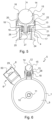
- FIG 8 represents, according to a detailed sectional view, the roll-on applicator of the bottle of figures 1 to 7 , when moving from the open position to the closed position of the bottle.
- the ball applicator 5 is in the retracted position.
- the transition from the deployed position to the retracted position is facilitated by chamfers 31 provided on the cap 8.
- the closure element 29 has chamfered edges parallel to the axis of rotation of the rotary shutter, so that the chamfers 31 thus formed come into contact with the ball holder and/or the ball when moving from the open position to the closed position.
- the chamfers 31 are positioned and configured so that they form the first surface in contact with the ball applicator when closing the bottle, so as to direct the force resulting from this contact substantially towards the inside of the bottle, and thus facilitate the retraction of the ball holder 13 and the ball 12.
- the chamfers 31 can be replaced by other shapes making it possible to prevent a sharp edge of the sealing means 29 from coming into contact with the ball 12.
- rounded edges or fillets can be formed.
- a particular shape of tank has been described in detail, but other shapes can be envisaged within the framework of the present invention, in particular any shape of revolution including a sphere, an oval shape or ovoid, a parallelepiped shape topped or not by a rounded shape such as a half disc, etc.
- the shaft 11 can alternatively be replaced by two cylindrical studs formed on the inner faces (located towards the reservoir 1) of the uprights 7 of the rotary shutter 6, so as to be introduced on either side of the passage formed by the inner wall 10.
- the passage can be replaced by two cavities formed in the wall of the reservoir 11.
- Other means allowing the rotation of the rotary shutter are also conceivable without departing from the scope of the invention.
- a circular or arc-shaped boss can be formed on each of the inner faces of the uprights 7. The boss is engaged in a circular or arc-shaped groove of corresponding radius and formed in the wall of the reservoir 1.
- the axis of rotation of the rotary shutter can be formed at any part of the bottle, including the dispensing head.
- the coil spring of the embodiment described above may be replaced by any suitable elastic means, including leaf springs and elements made of resilient materials such as rubber or silicone, or may have a different arrangement than that presented in the invention.
- the bottle may have a ball applicator of which only the ball (and not the assembly comprising the ball and the ball holder) is movable between the open position and the closed position.
- the bottle may have a fixed ball applicator, the resilient or movable elements allowing the closure and sealing of the bottle being carried in the cap of the rotary shutter.
- the bottle thus developed in the invention provides, thanks to the use of a rotating shutter, a compact and leak-proof roll-on applicator when the bottle is in the closed position, while benefiting from great ease of use. It also has the advantage of offering a captive shutter. Finally, the alternative to the caps known in the prior art offered by the subject of the present invention allows, according to certain embodiments, the obtaining of a bottle having a distinctive and attractive aesthetic for the user.
Landscapes
- Closures For Containers (AREA)
Claims (7)
- Flasche, umfassend einen Behälter (1), der ein Innenvolumen (9) aufweist, das dazu angepasst ist, ein flüssiges oder halbflüssiges Produkt zu enthalten, und einen Abgabekopf (2), der sich entlang einer Hauptachse (A) von dem Behälter vorstehend erstreckt, wobei der Abgabekopf (2) einen Roll-On-Applikator (5) umfasst, der einen Kugelträger (13) umfasst, in dem eine Kugel (12) frei drehbar eingeschlossen ist und aus dem eine Kalotte (14) der Kugel auf der dem Behälter (1) entgegengesetzten Seite herausragt,wobei die Flasche einen drehbaren Verschluss (6) umfasst, der dazu angepasst ist, in einer geschlossenen Position der Flasche den Roll-On-Applikator (5) abzudecken und für die Abgabe des Produkts in einer geöffneten Position der Flasche von dem Roll-On-Applikator (5) entfernt zu sein, wobei der drehbare Verschluss (6) in Bezug auf den Rest der Flasche um eine Drehachse (R) drehbar ist, die die Hauptachse (A) senkrecht schneidet,wobei der Roll-On-Applikator (5) einen Applikatorkörper (18) umfasst, in dem der Kugelträger (13) entlang der Hauptachse (A) translatorisch beweglich montiert ist,wobei der Roll-On-Applikator (5) ein elastisches Mittel umfasst, das zwischen dem Applikatorkörper (18) und dem Kugelträger (13) eingefügt ist,und wobei der Roll-On-Applikator so konfiguriert ist, dass sich die Kugel (12) zusammen mit dem Kugelträger (13) entlang der Hauptachse (A) translatorisch bewegen kann, um eine eingefahrene Position in dem Abgabekopf (2) einzunehmen, wenn der Roll-On-Applikator (5) in der geschlossenen Position der Flasche von dem drehbaren Verschluss (6) abgedeckt wird und das elastische Mittel dabei zusammengedrückt wird, und um bei einer Entspannung des elastischen Mittels eine ausgefahrene Position außerhalb des Abgabekopfes (2) einzunehmen, wenn der drehbare Verschluss (6) von dem Roll-On-Applikator (5) entfernt ist,wobei der drehbare Verschluss (6) eine Abdeckung (8) umfasst, in der ein Verschlusselement (29) angeordnet ist, das eine Konkavität (30) mit einer Form umfasst, die zu derjenigen der Kalotte (14) der Kugel (12), die von dem Kugelträger (13) vorsteht, komplementär ist, wobei das Verschlusselement an der Oberseite des Kugelträgers zur Anlage kommt, wenn die Kugel in die Konkavität (30) eingeführt ist.
- Flasche nach Anspruch 1, wobei der Kugelträger (13) eine Zuleitung (17) für das Produkt umfasst, die sich entlang der Hauptachse (A) in Richtung des Innenvolumens (9) erstreckt, und der Applikatorkörper (18) ein oberes Volumen (19) umfasst, das von dem Innenvolumen (9) des Behälters (1) durch eine Trennwand (25) getrennt ist, welche in ihrer Mitte einen Schacht (26) umfasst, der im unteren Teil durch einen Boden (27) geschlossen ist, wobei die Wände des Schachts (26) mindestens eine Öffnung umfassen, wobei die Flasche so konfiguriert ist, dass, wenn sie sich in der geschlossenen Position befindet, die Zuleitung (17) die Öffnung verschließt, und, wenn sie sich in der geöffneten Position befindet, die Öffnung freiliegt.
- Flasche nach einem der vorhergehenden Ansprüche, wobei das elastische Mittel eine Spiralfeder (28) ist.
- Flasche nach einem der vorhergehenden Ansprüche, wobei das Verschlusselement (29) ein nachgiebiges Element umfasst.
- Flasche nach einem der vorhergehenden Ansprüche, wobei das Verschlusselement (29) abgeschrägte Kanten parallel zu der Drehachse (R) des drehbaren Verschlusses (6) aufweist, wobei die so gebildeten Kanten (31) beim Übergang von der geöffneten Position in die geschlossene Position mit der Kugel (12) in Kontakt kommen.
- Flasche nach einem der vorhergehenden Ansprüche, wobei der Behälter (1) eine rotationssymmetrische Außenform aufweist, wobei die Drehachse (R) des drehbaren Verschlusses (6) mit einer Rotationsachse der Außenform des Behälters (1) zusammenfällt.
- Flasche nach Anspruch 6, wobei der Behälter (1) eine zylindrische Außenform aufweist, deren Höhe kleiner als oder gleich ihrem Radius (r) ist.
Applications Claiming Priority (2)
| Application Number | Priority Date | Filing Date | Title |
|---|---|---|---|
| FR1858802A FR3086146B1 (fr) | 2018-09-26 | 2018-09-26 | Flacon comportant un applicateur a bille et un obturateur |
| PCT/FR2019/052220 WO2020065189A1 (fr) | 2018-09-26 | 2019-09-23 | Flacon comportant un applicateur à bille et un obturateur |
Publications (2)
| Publication Number | Publication Date |
|---|---|
| EP3855974A1 EP3855974A1 (de) | 2021-08-04 |
| EP3855974B1 true EP3855974B1 (de) | 2025-05-21 |
Family
ID=65243886
Family Applications (1)
| Application Number | Title | Priority Date | Filing Date |
|---|---|---|---|
| EP19790687.8A Active EP3855974B1 (de) | 2018-09-26 | 2019-09-23 | Flasche mit einem roll-on-applikator und einem stopfen |
Country Status (5)
| Country | Link |
|---|---|
| US (1) | US11503896B2 (de) |
| EP (1) | EP3855974B1 (de) |
| ES (1) | ES3036163T3 (de) |
| FR (1) | FR3086146B1 (de) |
| WO (1) | WO2020065189A1 (de) |
Citations (1)
| Publication number | Priority date | Publication date | Assignee | Title |
|---|---|---|---|---|
| US8500355B2 (en) * | 2011-10-19 | 2013-08-06 | Allen & Thomas Cosmetic Accessories Co., Ltd. | Liquid dispensing massage device with switch lock |
Family Cites Families (7)
| Publication number | Priority date | Publication date | Assignee | Title |
|---|---|---|---|---|
| FR1018517A (fr) * | 1950-05-16 | 1953-01-08 | Dispositif pour l'application du rouge à lèvres ou des fards | |
| US2912708A (en) * | 1958-03-24 | 1959-11-17 | Owens Illinois Glass Co | Applicating device |
| US3055041A (en) * | 1961-01-04 | 1962-09-25 | Owens Illinois Glass Co | Ball applicator assembly with shuttletype closure |
| US4168128A (en) * | 1977-11-21 | 1979-09-18 | Owens-Illinois, Inc. | Seal roller dispensing package |
| DE19953258C2 (de) * | 1999-11-04 | 2003-04-10 | Henkel Kgaa | Vorrichtung zur Ausgabe eines fließfähigen Produktes aus einem Behälter |
| US20100329771A1 (en) * | 2009-06-29 | 2010-12-30 | Jun Zhang | Rolling ball style cosmetic container structure |
| FR3019718B1 (fr) | 2014-04-14 | 2016-05-13 | Cosmogen Sas | Tete d’application d’un produit, en particulier pour des soins de la peau, comportant une bille d’application maintenue par un aimant |
-
2018
- 2018-09-26 FR FR1858802A patent/FR3086146B1/fr active Active
-
2019
- 2019-09-23 EP EP19790687.8A patent/EP3855974B1/de active Active
- 2019-09-23 ES ES19790687T patent/ES3036163T3/es active Active
- 2019-09-23 WO PCT/FR2019/052220 patent/WO2020065189A1/fr not_active Ceased
- 2019-09-23 US US17/280,041 patent/US11503896B2/en active Active
Patent Citations (1)
| Publication number | Priority date | Publication date | Assignee | Title |
|---|---|---|---|---|
| US8500355B2 (en) * | 2011-10-19 | 2013-08-06 | Allen & Thomas Cosmetic Accessories Co., Ltd. | Liquid dispensing massage device with switch lock |
Also Published As
| Publication number | Publication date |
|---|---|
| FR3086146A1 (fr) | 2020-03-27 |
| US11503896B2 (en) | 2022-11-22 |
| WO2020065189A1 (fr) | 2020-04-02 |
| ES3036163T3 (en) | 2025-09-15 |
| EP3855974A1 (de) | 2021-08-04 |
| FR3086146B1 (fr) | 2022-01-28 |
| US20220000244A1 (en) | 2022-01-06 |
Similar Documents
| Publication | Publication Date | Title |
|---|---|---|
| CA2121655C (fr) | Dispositif de distribution d'une dose de volume determine d'un produit liquide ou pateux | |
| EP1208765B1 (de) | Stift , insbesondere für ein creme- ,gel- oder pastenartiges Produkt | |
| FR2960749A1 (fr) | Contenant cosmetique | |
| CA2353316C (fr) | Dispositif de conditionnement et de distribution permettant de distribuer une dose variable | |
| FR2745552A1 (fr) | Tete et ensemble de distribution de produit de consistance liquide a visqueuse, comportant un reducteur d'ecoulement | |
| CH650212A5 (fr) | Dispositif distributeur doseur. | |
| EP1169241B1 (de) | Vorrichtung zum schliessen der abgabeöffnung eines flüssigkeitsspenders | |
| WO2010106235A1 (fr) | Ensemble comprenant un systeme de conditionnement d'un produit a fermeture etanche. | |
| EP3665103B1 (de) | Vorrichtung zur abgabe eines produktes in form von kugeln | |
| EP2734080B1 (de) | System zum aufbewahren und auftragen eines produkts, insbesondere eines kosmetikprodukts | |
| EP3657978B1 (de) | Vorrichtung zur ausgabe und zum auftragen eines kosmetik- oder pflegeprodukts | |
| FR2811639A1 (fr) | Dispositif pour le conditionnement et la distribution d'un produit, notamment un produit capillaire | |
| FR3136936A1 (fr) | Récipient pour produits cosmétiques | |
| EP1661822B1 (de) | Verpackung und Ausgabevorrichtung für ein Produkt | |
| FR2882505A1 (fr) | Tube distributeur de produits cremeux | |
| WO2020065189A1 (fr) | Flacon comportant un applicateur à bille et un obturateur | |
| FR2653643A1 (fr) | Baton applicateur de produit pateux. | |
| EP3654800B1 (de) | Nockenmechanismus, insbesondere für einen kosmetikproduktapplikator | |
| FR2836345A1 (fr) | Applicateur doseur a bille | |
| EP2983549B1 (de) | Verpackungsvorrichtung für ein kosmetikprodukt, insbesondere für ein entgasungskosmetikprodukt | |
| EP1502872B1 (de) | Vorrichtung mit einem Doppelabgabesystem | |
| FR2876557A1 (fr) | Stylo distributeur d'un produit cosmetique fluide | |
| WO2015028759A1 (fr) | Dispositif de conditionnement et de distribution d'un produit cosmetique | |
| EP2887832B1 (de) | Applikator für ein kosmetikum, entsprechendes kit und entsprechendes verfahren | |
| FR2861707A1 (fr) | Dispositif de conditionnement et de distribution d'un produit fluide |
Legal Events
| Date | Code | Title | Description |
|---|---|---|---|
| STAA | Information on the status of an ep patent application or granted ep patent |
Free format text: STATUS: UNKNOWN |
|
| STAA | Information on the status of an ep patent application or granted ep patent |
Free format text: STATUS: THE INTERNATIONAL PUBLICATION HAS BEEN MADE |
|
| PUAI | Public reference made under article 153(3) epc to a published international application that has entered the european phase |
Free format text: ORIGINAL CODE: 0009012 |
|
| STAA | Information on the status of an ep patent application or granted ep patent |
Free format text: STATUS: REQUEST FOR EXAMINATION WAS MADE |
|
| 17P | Request for examination filed |
Effective date: 20210406 |
|
| AK | Designated contracting states |
Kind code of ref document: A1 Designated state(s): AL AT BE BG CH CY CZ DE DK EE ES FI FR GB GR HR HU IE IS IT LI LT LU LV MC MK MT NL NO PL PT RO RS SE SI SK SM TR |
|
| DAV | Request for validation of the european patent (deleted) | ||
| DAX | Request for extension of the european patent (deleted) | ||
| STAA | Information on the status of an ep patent application or granted ep patent |
Free format text: STATUS: EXAMINATION IS IN PROGRESS |
|
| 17Q | First examination report despatched |
Effective date: 20230512 |
|
| GRAP | Despatch of communication of intention to grant a patent |
Free format text: ORIGINAL CODE: EPIDOSNIGR1 |
|
| STAA | Information on the status of an ep patent application or granted ep patent |
Free format text: STATUS: GRANT OF PATENT IS INTENDED |
|
| INTG | Intention to grant announced |
Effective date: 20250212 |
|
| GRAS | Grant fee paid |
Free format text: ORIGINAL CODE: EPIDOSNIGR3 |
|
| GRAA | (expected) grant |
Free format text: ORIGINAL CODE: 0009210 |
|
| STAA | Information on the status of an ep patent application or granted ep patent |
Free format text: STATUS: THE PATENT HAS BEEN GRANTED |
|
| AK | Designated contracting states |
Kind code of ref document: B1 Designated state(s): AL AT BE BG CH CY CZ DE DK EE ES FI FR GB GR HR HU IE IS IT LI LT LU LV MC MK MT NL NO PL PT RO RS SE SI SK SM TR |
|
| REG | Reference to a national code |
Ref country code: GB Ref legal event code: FG4D Free format text: NOT ENGLISH |
|
| REG | Reference to a national code |
Ref country code: CH Ref legal event code: EP |
|
| REG | Reference to a national code |
Ref country code: DE Ref legal event code: R096 Ref document number: 602019070288 Country of ref document: DE |
|
| REG | Reference to a national code |
Ref country code: IE Ref legal event code: FG4D Free format text: LANGUAGE OF EP DOCUMENT: FRENCH |
|
| REG | Reference to a national code |
Ref country code: ES Ref legal event code: FG2A Ref document number: 3036163 Country of ref document: ES Kind code of ref document: T3 Effective date: 20250915 |
|
| REG | Reference to a national code |
Ref country code: NL Ref legal event code: MP Effective date: 20250521 |
|
| PG25 | Lapsed in a contracting state [announced via postgrant information from national office to epo] |
Ref country code: PT Free format text: LAPSE BECAUSE OF FAILURE TO SUBMIT A TRANSLATION OF THE DESCRIPTION OR TO PAY THE FEE WITHIN THE PRESCRIBED TIME-LIMIT Effective date: 20250922 Ref country code: FI Free format text: LAPSE BECAUSE OF FAILURE TO SUBMIT A TRANSLATION OF THE DESCRIPTION OR TO PAY THE FEE WITHIN THE PRESCRIBED TIME-LIMIT Effective date: 20250521 |
|
| PGFP | Annual fee paid to national office [announced via postgrant information from national office to epo] |
Ref country code: DE Payment date: 20250926 Year of fee payment: 7 |
|
| REG | Reference to a national code |
Ref country code: LT Ref legal event code: MG9D |
|
| PG25 | Lapsed in a contracting state [announced via postgrant information from national office to epo] |
Ref country code: GR Free format text: LAPSE BECAUSE OF FAILURE TO SUBMIT A TRANSLATION OF THE DESCRIPTION OR TO PAY THE FEE WITHIN THE PRESCRIBED TIME-LIMIT Effective date: 20250822 Ref country code: NO Free format text: LAPSE BECAUSE OF FAILURE TO SUBMIT A TRANSLATION OF THE DESCRIPTION OR TO PAY THE FEE WITHIN THE PRESCRIBED TIME-LIMIT Effective date: 20250821 |
|
| PG25 | Lapsed in a contracting state [announced via postgrant information from national office to epo] |
Ref country code: PL Free format text: LAPSE BECAUSE OF FAILURE TO SUBMIT A TRANSLATION OF THE DESCRIPTION OR TO PAY THE FEE WITHIN THE PRESCRIBED TIME-LIMIT Effective date: 20250521 Ref country code: NL Free format text: LAPSE BECAUSE OF FAILURE TO SUBMIT A TRANSLATION OF THE DESCRIPTION OR TO PAY THE FEE WITHIN THE PRESCRIBED TIME-LIMIT Effective date: 20250521 |
|
| PG25 | Lapsed in a contracting state [announced via postgrant information from national office to epo] |
Ref country code: BG Free format text: LAPSE BECAUSE OF FAILURE TO SUBMIT A TRANSLATION OF THE DESCRIPTION OR TO PAY THE FEE WITHIN THE PRESCRIBED TIME-LIMIT Effective date: 20250521 |
|
| PGFP | Annual fee paid to national office [announced via postgrant information from national office to epo] |
Ref country code: GB Payment date: 20250826 Year of fee payment: 7 |
|
| PG25 | Lapsed in a contracting state [announced via postgrant information from national office to epo] |
Ref country code: HR Free format text: LAPSE BECAUSE OF FAILURE TO SUBMIT A TRANSLATION OF THE DESCRIPTION OR TO PAY THE FEE WITHIN THE PRESCRIBED TIME-LIMIT Effective date: 20250521 |
|
| PGFP | Annual fee paid to national office [announced via postgrant information from national office to epo] |
Ref country code: FR Payment date: 20250925 Year of fee payment: 7 |
|
| PG25 | Lapsed in a contracting state [announced via postgrant information from national office to epo] |
Ref country code: RS Free format text: LAPSE BECAUSE OF FAILURE TO SUBMIT A TRANSLATION OF THE DESCRIPTION OR TO PAY THE FEE WITHIN THE PRESCRIBED TIME-LIMIT Effective date: 20250821 |
|
| PG25 | Lapsed in a contracting state [announced via postgrant information from national office to epo] |
Ref country code: IS Free format text: LAPSE BECAUSE OF FAILURE TO SUBMIT A TRANSLATION OF THE DESCRIPTION OR TO PAY THE FEE WITHIN THE PRESCRIBED TIME-LIMIT Effective date: 20250921 |
|
| PG25 | Lapsed in a contracting state [announced via postgrant information from national office to epo] |
Ref country code: LV Free format text: LAPSE BECAUSE OF FAILURE TO SUBMIT A TRANSLATION OF THE DESCRIPTION OR TO PAY THE FEE WITHIN THE PRESCRIBED TIME-LIMIT Effective date: 20250521 |
|
| REG | Reference to a national code |
Ref country code: AT Ref legal event code: MK05 Ref document number: 1796015 Country of ref document: AT Kind code of ref document: T Effective date: 20250521 |
|
| PG25 | Lapsed in a contracting state [announced via postgrant information from national office to epo] |
Ref country code: AT Free format text: LAPSE BECAUSE OF FAILURE TO SUBMIT A TRANSLATION OF THE DESCRIPTION OR TO PAY THE FEE WITHIN THE PRESCRIBED TIME-LIMIT Effective date: 20250521 Ref country code: DK Free format text: LAPSE BECAUSE OF FAILURE TO SUBMIT A TRANSLATION OF THE DESCRIPTION OR TO PAY THE FEE WITHIN THE PRESCRIBED TIME-LIMIT Effective date: 20250521 Ref country code: SM Free format text: LAPSE BECAUSE OF FAILURE TO SUBMIT A TRANSLATION OF THE DESCRIPTION OR TO PAY THE FEE WITHIN THE PRESCRIBED TIME-LIMIT Effective date: 20250521 |
|
| PGFP | Annual fee paid to national office [announced via postgrant information from national office to epo] |
Ref country code: IT Payment date: 20250926 Year of fee payment: 7 |
|
| PG25 | Lapsed in a contracting state [announced via postgrant information from national office to epo] |
Ref country code: CZ Free format text: LAPSE BECAUSE OF FAILURE TO SUBMIT A TRANSLATION OF THE DESCRIPTION OR TO PAY THE FEE WITHIN THE PRESCRIBED TIME-LIMIT Effective date: 20250521 |
|
| PG25 | Lapsed in a contracting state [announced via postgrant information from national office to epo] |
Ref country code: EE Free format text: LAPSE BECAUSE OF FAILURE TO SUBMIT A TRANSLATION OF THE DESCRIPTION OR TO PAY THE FEE WITHIN THE PRESCRIBED TIME-LIMIT Effective date: 20250521 |
|
| PG25 | Lapsed in a contracting state [announced via postgrant information from national office to epo] |
Ref country code: SK Free format text: LAPSE BECAUSE OF FAILURE TO SUBMIT A TRANSLATION OF THE DESCRIPTION OR TO PAY THE FEE WITHIN THE PRESCRIBED TIME-LIMIT Effective date: 20250521 Ref country code: RO Free format text: LAPSE BECAUSE OF FAILURE TO SUBMIT A TRANSLATION OF THE DESCRIPTION OR TO PAY THE FEE WITHIN THE PRESCRIBED TIME-LIMIT Effective date: 20250521 |
|
| PGFP | Annual fee paid to national office [announced via postgrant information from national office to epo] |
Ref country code: ES Payment date: 20251010 Year of fee payment: 7 |
|
| REG | Reference to a national code |
Ref country code: DE Ref legal event code: R097 Ref document number: 602019070288 Country of ref document: DE |
|
| PLBE | No opposition filed within time limit |
Free format text: ORIGINAL CODE: 0009261 |
|
| STAA | Information on the status of an ep patent application or granted ep patent |
Free format text: STATUS: NO OPPOSITION FILED WITHIN TIME LIMIT |
|
| REG | Reference to a national code |
Ref country code: CH Ref legal event code: L10 Free format text: ST27 STATUS EVENT CODE: U-0-0-L10-L00 (AS PROVIDED BY THE NATIONAL OFFICE) Effective date: 20260402 |
|
| 26N | No opposition filed |
Effective date: 20260224 |
|
| REG | Reference to a national code |
Ref country code: CH Ref legal event code: H13 Free format text: ST27 STATUS EVENT CODE: U-0-0-H10-H13 (AS PROVIDED BY THE NATIONAL OFFICE) Effective date: 20260504 |