EP3857521B1 - Système d'accès - Google Patents
Système d'accès Download PDFInfo
- Publication number
- EP3857521B1 EP3857521B1 EP19770141.0A EP19770141A EP3857521B1 EP 3857521 B1 EP3857521 B1 EP 3857521B1 EP 19770141 A EP19770141 A EP 19770141A EP 3857521 B1 EP3857521 B1 EP 3857521B1
- Authority
- EP
- European Patent Office
- Prior art keywords
- door
- unit
- sensor
- transponder
- reading unit
- Prior art date
- Legal status (The legal status is an assumption and is not a legal conclusion. Google has not performed a legal analysis and makes no representation as to the accuracy of the status listed.)
- Active
Links
Images


Classifications
-
- G—PHYSICS
- G06—COMPUTING OR CALCULATING; COUNTING
- G06K—GRAPHICAL DATA READING; PRESENTATION OF DATA; RECORD CARRIERS; HANDLING RECORD CARRIERS
- G06K7/00—Methods or arrangements for sensing record carriers, e.g. for reading patterns
- G06K7/10—Methods or arrangements for sensing record carriers, e.g. for reading patterns by electromagnetic radiation, e.g. optical sensing; by corpuscular radiation
- G06K7/10009—Methods or arrangements for sensing record carriers, e.g. for reading patterns by electromagnetic radiation, e.g. optical sensing; by corpuscular radiation sensing by radiation using wavelengths larger than 0.1 mm, e.g. radio-waves or microwaves
- G06K7/10316—Methods or arrangements for sensing record carriers, e.g. for reading patterns by electromagnetic radiation, e.g. optical sensing; by corpuscular radiation sensing by radiation using wavelengths larger than 0.1 mm, e.g. radio-waves or microwaves using at least one antenna particularly designed for interrogating the wireless record carriers
- G06K7/10336—Methods or arrangements for sensing record carriers, e.g. for reading patterns by electromagnetic radiation, e.g. optical sensing; by corpuscular radiation sensing by radiation using wavelengths larger than 0.1 mm, e.g. radio-waves or microwaves using at least one antenna particularly designed for interrogating the wireless record carriers the antenna being of the near field type, inductive coil
-
- G—PHYSICS
- G07—CHECKING-DEVICES
- G07C—TIME OR ATTENDANCE REGISTERS; REGISTERING OR INDICATING THE WORKING OF MACHINES; GENERATING RANDOM NUMBERS; VOTING OR LOTTERY APPARATUS; ARRANGEMENTS, SYSTEMS OR APPARATUS FOR CHECKING NOT PROVIDED FOR ELSEWHERE
- G07C9/00—Individual registration on entry or exit
- G07C9/00174—Electronically operated locks; Circuits therefor; Nonmechanical keys therefor, e.g. passive or active electrical keys or other data carriers without mechanical keys
- G07C9/00309—Electronically operated locks; Circuits therefor; Nonmechanical keys therefor, e.g. passive or active electrical keys or other data carriers without mechanical keys operated with bidirectional data transmission between data carrier and locks
-
- G—PHYSICS
- G07—CHECKING-DEVICES
- G07C—TIME OR ATTENDANCE REGISTERS; REGISTERING OR INDICATING THE WORKING OF MACHINES; GENERATING RANDOM NUMBERS; VOTING OR LOTTERY APPARATUS; ARRANGEMENTS, SYSTEMS OR APPARATUS FOR CHECKING NOT PROVIDED FOR ELSEWHERE
- G07C9/00—Individual registration on entry or exit
- G07C9/00174—Electronically operated locks; Circuits therefor; Nonmechanical keys therefor, e.g. passive or active electrical keys or other data carriers without mechanical keys
- G07C9/00944—Details of construction or manufacture
-
- G—PHYSICS
- G07—CHECKING-DEVICES
- G07C—TIME OR ATTENDANCE REGISTERS; REGISTERING OR INDICATING THE WORKING OF MACHINES; GENERATING RANDOM NUMBERS; VOTING OR LOTTERY APPARATUS; ARRANGEMENTS, SYSTEMS OR APPARATUS FOR CHECKING NOT PROVIDED FOR ELSEWHERE
- G07C9/00—Individual registration on entry or exit
- G07C9/00174—Electronically operated locks; Circuits therefor; Nonmechanical keys therefor, e.g. passive or active electrical keys or other data carriers without mechanical keys
- G07C9/00309—Electronically operated locks; Circuits therefor; Nonmechanical keys therefor, e.g. passive or active electrical keys or other data carriers without mechanical keys operated with bidirectional data transmission between data carrier and locks
- G07C2009/00317—Electronically operated locks; Circuits therefor; Nonmechanical keys therefor, e.g. passive or active electrical keys or other data carriers without mechanical keys operated with bidirectional data transmission between data carrier and locks keyless data carrier having only one limited data transmission range
-
- G—PHYSICS
- G07—CHECKING-DEVICES
- G07C—TIME OR ATTENDANCE REGISTERS; REGISTERING OR INDICATING THE WORKING OF MACHINES; GENERATING RANDOM NUMBERS; VOTING OR LOTTERY APPARATUS; ARRANGEMENTS, SYSTEMS OR APPARATUS FOR CHECKING NOT PROVIDED FOR ELSEWHERE
- G07C9/00—Individual registration on entry or exit
- G07C9/00174—Electronically operated locks; Circuits therefor; Nonmechanical keys therefor, e.g. passive or active electrical keys or other data carriers without mechanical keys
- G07C2009/00753—Electronically operated locks; Circuits therefor; Nonmechanical keys therefor, e.g. passive or active electrical keys or other data carriers without mechanical keys operated by active electrical keys
- G07C2009/00761—Electronically operated locks; Circuits therefor; Nonmechanical keys therefor, e.g. passive or active electrical keys or other data carriers without mechanical keys operated by active electrical keys with data transmission performed by connected means, e.g. mechanical contacts, plugs, connectors
-
- G—PHYSICS
- G07—CHECKING-DEVICES
- G07C—TIME OR ATTENDANCE REGISTERS; REGISTERING OR INDICATING THE WORKING OF MACHINES; GENERATING RANDOM NUMBERS; VOTING OR LOTTERY APPARATUS; ARRANGEMENTS, SYSTEMS OR APPARATUS FOR CHECKING NOT PROVIDED FOR ELSEWHERE
- G07C9/00—Individual registration on entry or exit
- G07C9/00174—Electronically operated locks; Circuits therefor; Nonmechanical keys therefor, e.g. passive or active electrical keys or other data carriers without mechanical keys
- G07C9/00944—Details of construction or manufacture
- G07C2009/0096—Electronic keys comprising a non-biometric sensor
-
- G—PHYSICS
- G07—CHECKING-DEVICES
- G07C—TIME OR ATTENDANCE REGISTERS; REGISTERING OR INDICATING THE WORKING OF MACHINES; GENERATING RANDOM NUMBERS; VOTING OR LOTTERY APPARATUS; ARRANGEMENTS, SYSTEMS OR APPARATUS FOR CHECKING NOT PROVIDED FOR ELSEWHERE
- G07C2209/00—Indexing scheme relating to groups G07C9/00 - G07C9/38
- G07C2209/08—With time considerations, e.g. temporary activation, valid time window or time limitations
-
- G—PHYSICS
- G07—CHECKING-DEVICES
- G07C—TIME OR ATTENDANCE REGISTERS; REGISTERING OR INDICATING THE WORKING OF MACHINES; GENERATING RANDOM NUMBERS; VOTING OR LOTTERY APPARATUS; ARRANGEMENTS, SYSTEMS OR APPARATUS FOR CHECKING NOT PROVIDED FOR ELSEWHERE
- G07C2209/00—Indexing scheme relating to groups G07C9/00 - G07C9/38
- G07C2209/60—Indexing scheme relating to groups G07C9/00174 - G07C9/00944
- G07C2209/63—Comprising locating means for detecting the position of the data carrier, i.e. within the vehicle or within a certain distance from the vehicle
- G07C2209/64—Comprising locating means for detecting the position of the data carrier, i.e. within the vehicle or within a certain distance from the vehicle using a proximity sensor
-
- G—PHYSICS
- G07—CHECKING-DEVICES
- G07C—TIME OR ATTENDANCE REGISTERS; REGISTERING OR INDICATING THE WORKING OF MACHINES; GENERATING RANDOM NUMBERS; VOTING OR LOTTERY APPARATUS; ARRANGEMENTS, SYSTEMS OR APPARATUS FOR CHECKING NOT PROVIDED FOR ELSEWHERE
- G07C2209/00—Indexing scheme relating to groups G07C9/00 - G07C9/38
- G07C2209/60—Indexing scheme relating to groups G07C9/00174 - G07C9/00944
- G07C2209/63—Comprising locating means for detecting the position of the data carrier, i.e. within the vehicle or within a certain distance from the vehicle
- G07C2209/65—Comprising locating means for detecting the position of the data carrier, i.e. within the vehicle or within a certain distance from the vehicle using means for sensing the user's hand
Definitions
- the invention relates to an access system according to the preamble of claim 1.
- Embodiments are the subject of claims 2 to 12.
- the detection area is usually so small that the transponder practically has to be placed on the reading unit or at least come very close to it.
- Active transponders are also conceivable, which send out an identification immediately after receiving a radio signal or respond to a radio signal after an input device, such as a button, is pressed.
- an input device such as a button
- the access control system is therefore designed to read and identify a transponder located near the respective reading unit via the first reading unit and/or the second reading unit. This means that it is checked whether the transponder is one that was previously announced to the system and has access authorization. If such a transponder is recognized, there is basic authorization to open the door.
- an investigation is first carried out to determine where an authorized transponder is located.
- the evaluation unit can be designed to ignore an authorized transponder on the inside. If the transponder is a transponder that can be activated by pressing a button or by some other actuation, this can affect a situation in which a transponder is still active and has already triggered a door opening signal to open the door from the outside. If it is then located on the inside of the door, this cannot trigger another door opening signal. However, if an authorized transponder on the outside of the door approaches, it can trigger the generation of a door opening signal.
- the transponder To determine the position of the transponder, it can be useful to determine the distances between the transponder and both reading units. By then comparing the two distances, it becomes immediately clear which of the two reading units the transponder in question is positioned closer to. If the distance determined to the first reading unit is smaller than to the second reading unit, it can be assumed that the transponder is on the outside. If the distance to the second reading unit is smaller, it can be assumed that the transponder is on the inside of the door.
- the distance can be determined by evaluating the measured field or signal strength of the transponder's response signal at the reading units. Alternatively, a signal propagation time between a respective reading unit and the transponder can be determined. If two independent evaluation units are used, each of these could be designed to measure a field strength or a propagation time. However, a single evaluation unit could be preferred to avoid errors. It is also conceivable to use each reading unit to be equipped with a corresponding circuit that enables distance measurement. The measured values of both evaluation units or the distance values determined from them can be compared in one of the two evaluation units or transmitted to another evaluation unit that serves only this purpose. It may be useful to actually read a transponder using only one of the reading units, while the other of the reading units, in particular the second one, could be intended exclusively for carrying out the distance measurement.
- the access system according to the invention provides a very convenient way to prevent unintentional opening of a door that can be locked by means of a motor lock or similar device.
- the at least one evaluation unit is designed to determine the distance by evaluating a measured signal strength or signal propagation time of a response signal of the transponder at the reading units.
- the first reading unit and the second reading unit are coupled to a common evaluation unit. This reduces the complexity of the system.
- the location of the transponder can be determined directly in the common evaluation unit by comparing field or signal strengths or signal propagation times.
- the installation heights of the first reading unit and the second reading unit differ from each other by a maximum of 7 cm. Too great a vertical offset between the two reading units could lead to an inaccurate determination of the location of the transponder. In such a case, it would be possible for a transponder on the outside of the door to be brought closer to the second reading unit than to the first reading unit. The transponder would then be incorrectly located as being on the inside of the door.
- the installation heights of the first reading unit and the second reading unit differ by a maximum of 5 cm.
- the first reading unit has an active surface that is located in a section of the first actuating handle and is flush with an outer surface of the first actuating handle.
- the range and thus the first detection area can thus be set precisely and implemented without interference.
- the first actuating handle consequently has through-holes for inserting a tool into the cavity for driving screws for clamping or releasing the first reading unit and/or the sensor.
- the at least one covering element has a second covering element which is at least partially made of a plastic and is arranged on a side of the first covering element facing the handle part.
- the plastic version can be used to cover the window without affecting the detection area, at least in the direction facing the user.
- the carrier is preferably made of a plastic. Injection molding can be used to inexpensively produce a complex structure of practically any shape that is suitable for the realization of the receiving sections.
- the at least one evaluation unit is designed to emit a visual or acoustic indication when an identified transponder is located on the outside. This can involve at least a brief flashing or at least a brief emitting of an indication tone.
- the first transponder is in the second detection area of the second reading unit. If the first transponder is a transponder that can be activated by pressing a button, it is assumed that the first transponder is (still) activated, for example by previously opening the door.
- the first or second reading unit could then read in an identifier or other identification feature of the first transponder. It may be advisable to check access authorization immediately after reading. This can be done by comparing the read identifier of the first transponder with predefined, i.e. stored, transponder identifiers. If the identifier of the first transponder is present in a corresponding data set, it is recognized as having access authorization. Afterwards or during this, the position of the first transponder is determined.
- a transponder identifier is read in and an attempt is made to identify the transponder. If the identification is successful, i.e. the transponder is authorized to enter, a door opening signal is generated to initiate the opening of the motor lock.
- the sensor for detecting an object in the third detection area would then be activated and wait for an actuation by a user. This can be accompanied by an activation of the lighting unit, so that a user is directly informed that a corresponding input is expected in order to send the door opening signal to the motor lock.
- a transponder 16 is shown which is located on the outside and, due to the designs of the first reading unit 10 and the second reading unit 12, falls within the detection ranges of both reading units 10 and 12.
- the evaluation unit 14 is designed to determine a distance D1 from the first reading unit 10 to the transponder 16 and a distance D2 from the second reading unit 14 to the transponder 16. This could be done by determining a field or signal strength of a response signal sent out by the transponder 16. Alternatively, it would be conceivable to determine a signal propagation time. By determining the distances D1 and D2, the evaluation unit 14 can determine whether the transponder 16 is located on the outside or the inside of the door 4. If the distance D1 is less than D2, this indicates that it is positioned on the outside.
- the evaluation unit 14 does not necessarily have to be able to calculate concrete distance values. Rather, it would be sufficient to determine parameters that depend on the distance between the transponder 16 and the respective reading units 10 and 12. These distance-dependent parameters can then be compared with one another.
- the sensor 22 has a third detection area 28 in which the presence of an object can be detected after identifying a transponder authorized for opening on the outside of the door 4.
- the sensor 22 can be understood in the broadest sense as an input device that can be triggered by a gesture with a foot or hand and is used to actually control the opening of the motor lock 18, for example by releasing or confirming the sending of a door opening signal generated by the evaluation unit 14.
- the third detection area 28 can extend outwards from a first end 30 as the first section of the first actuating handle 6.
- the third detection area 28 is concentrated, for example, on an approximately cylindrical, conical or club-shaped area that extends outwards from the sensor 22.
- the orientation of the sensor 22 produces an extension direction of the third detection area 28 that essentially coincides with a main extension axis 32 of the first actuating handle 6.
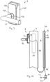
- the third detection area 28 therefore extends from a lower end of the first actuating handle 6 to a floor 34 in front of the door 4. If an object enters this third detection area 28 that is shown in a detailed representation in Fig. 2 B is shown as a foot or shoe 35 for example, this can be detected by the sensor 22.
- a lighting unit (not shown here) which projects a light spot 36 onto the floor 34.
- Fig. 3 shows a section of the first actuating handle 6, in which the first reading unit 10 is integrated.
- the first actuating handle 6 has a cross-section that is curved on one side but flattened on the other side.
- a curved side 54 can be turned towards the door 4 in an installed state, while a flattened side 38 then points away from the door 4.
- the first reading unit 10 is integrated into the first actuating handle 6 in the form of a closed structural unit, which is referred to below as the first structural unit 40.
- This first structural unit 40 has a first housing 42 which surrounds the first reading unit 6. Threaded holes 48 are provided at two ends 44 and 46, into which screws 50 are screwed.
- the first actuating handle 6 has through holes 52 on its curved side 54, each positioned in alignment with the threaded holes 48, through which a user can insert a tool for turning the screws 50. If the screws 50 are unscrewed from the respective threaded bore 48, they hit an inner side of the first actuating handle 6 and consequently clamp the first housing 42 in the cavity 20. This not only ensures a secure fastening of the first reading unit 10, but also an easy disassembly option.
- Fig. 4a shows the first assembly 40 in an enlarged view.
- the first housing 42 is significantly larger than is necessary for the actual accommodation of the first reading unit 10.
- Electrical connection lines 56 are shown, which are led from the inside of the first housing 42 to the outside.
- the first reading unit 10 is completely and irreversibly surrounded by a waterproof shell and is robustly protected against external mechanical influences.
- the clamp 58 serves to seal the first housing 42.
- the first housing 42 can essentially have a tub shape in which one side is open and all other sides are closed or closable.
- the first actuating handle can have 6 different shapes, which are shown in the Figures 5b and 5c being represented.
- Fig. 5b shows a first actuating handle 6 with a substantially square cross-section.
- Fig. 5c shows a classic, completely cylindrical cross-section, as is often used in bar handles. While the active surface of the variants is 60 Figures 5a and 5b can be designed in the same way, the variant in Fig. 5c a curved version of the active surface 60 is used.
- FIGS. 6a and 6b show a second structural unit 66, which is to be positioned at the first end 30 of the first actuating handle 6 and has the sensor 22 arranged therein.
- a second housing 68 is provided which is adapted to the cavity 20 of the first actuating handle 6. It can therefore be inserted into the first actuating handle 6 through an opening in the first end 30.
- a threaded hole 70 is also provided here, in which a screw 72 is arranged. This is designed as a countersunk screw, for example. This also allows the second housing 68 and consequently the second structural unit 66 to be fastened in the cavity 20 of the first actuating handle 6.
- the second structural unit 66 is illustrated in an exploded view with the separate second housing 68.
- the second housing 68 has a first receiving space 78 which is designed to receive the sensor 22. This is arranged, for example, on a circuit board 80 which has a sensor evaluation circuit.
- a lighting unit 82 is shown in dashed lines, which is also located on the circuit board 80 and is arranged next to the sensor 22. This lighting unit 82 can be electrically coupled to the sensor 22 or the circuit board 80, so that when the sensor 22 is activated, the lighting unit 82 is also in operation and emits light.
- a lens 84 is provided for bundling the light, which can be introduced into a second receiving space 86. This is placed next to the first receiving space 78 in the second housing 68. If the sensor 22 and the lens 84 are introduced into the associated receiving spaces 78 and 86, the circuit board 80 lies flush on the second housing 68.
- the lighting unit 82 can be realized as a light-emitting diode soldered onto the circuit board 80, to which a first lens 83 is connected. For example, this can be arranged on the circuit board 80 via a carrier 88.
- the lens 84, the carrier 88 and the first lens 83 can be pre-assembled via a tube 89.
- an electrical connector 90 is placed on the circuit board 80 on a side facing away from the sensor 22 and the lighting unit 82.
- the connector 90 allows coupling in particular with the evaluation unit 14 or a similar, higher-level system.
- the circuit board 80 already has a sensor evaluation circuit that controls the sensor 22 and the lighting unit 82 and in particular evaluates signals or data provided by the sensor 22.
- the sensor evaluation circuit is preferably designed to detect an object located in the third detection area from the raw signals. A signal can then be provided via the electrical connector 90 that a corresponding object has been detected. It is then not necessary to send all signals from the sensor 22 to a higher-level unit in order to carry out processing there.
- Fig.8 shows the second actuating handle 8 in an exploded view.
- a handle part 92 is provided for operation, which is designed at a right angle and can be operated like a conventional door handle.
- a bearing device 98 which has a bearing frame 100 on which a pin bearing 102 is provided for supporting a first drive pin 104.
- the bearing frame 100 can be based on a sheet metal that is bent several times. During the bent process, two side tabs 106 are formed, which run essentially parallel to one another.
- a base tab 108 is provided on an underside, which runs essentially between the two side tabs perpendicular to the side tabs 106. The tabs 106 and 108 do not have to be connected to one another.
- a first receiving section 110 of the carrier 94 is designed as a projection with two side surfaces 112, which are designed to correspond with the side tabs 106.
- the bearing frame 100 can therefore be placed on the first receiving section 110 so that the two side tabs 106 are pushed or placed on the two side surfaces 112 of the carrier 94.
- an at least temporary positive or non-positive connection can be produced between the bearing frame 100 and the carrier 94.
- a second receiving section 118 in the form of a recess is provided on a side of the carrier 94 opposite the bearing device 98.
- the second receiving section 118 can receive the second reading unit 12, which is arranged above the central axis 114 and in particular above the first cutout 96.
- the second reading unit 12 is then located above the bearing device 98 and on a side of the carrier 94 facing away from it. As mentioned above, it can be useful to make the installation height of the first reading unit 10 and the second reading unit 12 essentially identical.
- the second reading unit 12 By arranging the second reading unit 12 on a side of the carrier 94 facing away from the handle part 92 and the bearing device 98, the second reading unit 12 can be protected from mechanical damage.
- the second reading unit 12 has, for example, an electrical connection line 120, which will be discussed further below.
- a return spring unit 122 is provided. This has in particular a spring assembly (not shown in detail here) that counteracts a rotation of the first drive pin 104 driven by the handle part 92.
- the return spring unit 122 can be connected to a second drive pin (not shown).
- the first drive pin 104 can also be designed in such a way that it extends into the Return spring unit 122 or beyond.
- the detailed design can be freely selected according to standard technical standards. It is also conceivable for the bearing device 98 to have a coupling on a side facing away from the handle part 92 for coupling to the first drive pin 104.
- the first drive pin 104 or a second drive pin should provide a connection to a motor lock or a latch mechanism (not shown here).
- a first covering element 124 is provided, which is made of a metallic material, for example.
- the first covering element 124 has a window 126 on a side above the central axis 114. This represents an opening that is aligned with the orientation of the second reading unit 12.
- the first covering element 124 is designed in the shape of a trough, so that the carrier 94 with the bearing device 98 arranged thereon is completely enclosed and covered from the outside.
- a second cutout 128 is provided for this purpose, through which the pin bearing 102 extends outwards.
- the frame 94 and the first covering element 124 are designed in a wedge shape.
- a second covering element 130 is provided, which is made in particular from a plastic.
- the plastic does not interfere with the radio signal between a transponder and the second reading unit 12.
- the second covering element 130 is arranged on a side of the first covering element 124 facing the handle part 92 and has a third cutout 132 through which the pin bearing 102 can extend outwards.
- a rosette 131 can be provided to cover the pin bearing 12. This can be followed by a tolerance sleeve 133 through which the handle part 92 can be guided.
- a cover 134 is provided on a rear side of the second actuating handle 8, the extent of which coincides with the surface extent of the carrier 94.
- Several threaded holes 136 are arranged here, which can accommodate screws (not shown here). These screws can extend through holes 138 in the bearing device 98, holes 140 in the carrier 98 and holes 142 in the return spring unit 122 and can be screwed into the threaded holes 136. This firmly connects all components to one another.
- an opening 144 is provided, which is formed, for example, as a notch. This adjoins a fourth cutout 146 for the passage of a drive pin.
- the Fig.10 shown cabling can be used.
- the first reading unit 10 is integrated in the cavity 20 of the first actuating handle 6.
- the Fig.4 The connecting lines 56 shown extend downwards in the cavity 20, for example, and each form a branch line.
- the connecting lines 56 can be provided as a Y-shaped arrangement.
- One of the two connecting lines 56 is connected to the second structural unit 66 or the sensor 22.
- the sensor 22 can be supplied with electrical power through these connecting lines 56.
- it can also be provided to implement a data or signal transmission to the first reading unit 10.
- the second connecting cable 56 is also led downwards through the cavity 20 and can be led via a holder 19 into the door 4 and there to the motor lock 18.
- This variant is particularly suitable when the first actuating handle 6 has a rod-shaped handle which is attached at points that are relatively far from the installation height of the first reading unit 10.
- the connecting cables 56 By leading the connecting cables 56 into the motor lock 18, the first reading unit 10 and the sensor 22 can therefore be supplied with power.
Landscapes
- Engineering & Computer Science (AREA)
- Physics & Mathematics (AREA)
- General Physics & Mathematics (AREA)
- Computer Networks & Wireless Communication (AREA)
- Toxicology (AREA)
- Health & Medical Sciences (AREA)
- Manufacturing & Machinery (AREA)
- Electromagnetism (AREA)
- General Health & Medical Sciences (AREA)
- Artificial Intelligence (AREA)
- Computer Vision & Pattern Recognition (AREA)
- Theoretical Computer Science (AREA)
- Lock And Its Accessories (AREA)
Claims (12)
- Système d'accès (2), possédant* une première poignée d'actionnement (6) destinée à être fixée à un côté extérieur d'une porte (4),* une deuxième poignée d'actionnement (8) destinée à être fixée à un côté intérieur de la porte (4), et* un système de contrôle d'accès comprenant au moins deux unités de lecture (10, 12) destinées à lire un transpondeur (16) et au moins une unité d'interprétation (14), laquelle est connectée à au moins une unité de lecture (10, 12) et est configurée pour identifier un transpondeur lu,* une première unité de lecture (10) destinée à être disposée sur le côté extérieur de la porte (4) et une deuxième unité de lecture (12) destinée à être disposée sur le côté intérieur de la porte (4) étant présentes, la première unité de lecture sur le côté extérieur de la porte possédant une première zone de détection et la deuxième unité de lecture sur le côté intérieur de la porte possédant une deuxième zone de détection, et* l'au moins une unité d'interprétation (14) étant configurée pour déterminer si un transpondeur (16) lu par le biais de la première unité de lecture (10) et/ou de la deuxième unité de lecture (12) et identifié dans l'au moins une unité d'interprétation (14) se trouve sur le côté intérieur ou le côté extérieur de la porte (4) et pour générer un signal d'ouverture de porte dans le cas d'un transpondeur (16) identifié qui se trouve sur le côté extérieur de la porte (4),
caractérisé en ce* que la première poignée d'actionnement est un dispositif qui sert à ouvrir et à fermer une porte, et en ce que la deuxième poignée d'actionnement est un dispositif qui sert à ouvrir et à fermer une porte,* qu'un capteur (22) connecté à l'au moins une unité d'interprétation (14), destiné à détecter un objet (35) qui se trouve dans une troisième zone de détection (28) définie par le capteur (22), est intégré dans la première poignée d'actionnement (6), le capteur (22) étant disposé au niveau d'une première potion de la première poignée d'actionnement (6) et la troisième zone de détection (28) s'étendant vers l'extérieur depuis la première portion, et l'au moins une unité d'interprétation (14) étant configurée pour activer le capteur (22) en vue de générer le signal d'ouverture de porte et n'émettre le signal d'ouverture de porte qu'après la détection d'un objet (35) dans la troisième zone de détection (28), et* que la première poignée d'actionnement (6) est configurée en forme de tige au moins dans certaines portions, possède une première extrémité (30) et une deuxième extrémité à l'opposé de la première extrémité (30), la première portion se trouvant à première extrémité (30), la première poignée d'actionnement (6) présentant la forme d'une poignée barre ou d'une poignée étrier, laquelle est configurée pour être disposée verticalement de telle sorte que le capteur est dirigé vers le bas, et la troisième zone de détection (28) du capteur (22) s'étendant vers un sol (34) devant la porte (4) . - Système d'accès (2) selon la revendication 1, caractérisé en ce que l'au moins une unité d'interprétation (14) est configurée pour déterminer l'écart par interprétation des intensités de signal mesurées ou du temps de propagation de signal mesuré d'un signal de réponse du transpondeur au niveau des unités de lecture (10, 12).
- Système d'accès (2) selon la revendication 1 ou 2, caractérisé en ce que la première unité de lecture (10) et la deuxième unité de lecture (12) sont connectées à une unité d'interprétation (14) commune.
- Système d'accès (2) selon l'une des revendications précédentes, caractérisé en ce que les hauteurs de montage de la première unité de lecture (10) et de la deuxième unité de lecture (12) se différencient au maximum de 7 cm l'une de l'autre.
- Système d'accès (2) selon l'une des revendications précédentes, caractérisé en ce que la première unité de lecture (10) est intégrées dans la première poignée d'actionnement (6).
- Système d'accès (2) selon l'une des revendications précédentes, caractérisé en ce que la première poignée d'actionnement (6) possède un axe d'extension principal (32) et la troisième zone de détection (28) suit un tracé parallèle à l'axe d'extension principal (32).
- Système d'accès (2) selon l'une des revendications précédentes, caractérisé en ce que le capteur (22) est un capteur à ultrasons.
- Système d'accès (2) selon la revendication 4, caractérisé en ce que la première unité de lecture (10) est disposée dans un premier boîtier (42) et forme un premier module (40).
- Système d'accès (2) selon l'une des revendications précédentes, caractérisé en ce que le capteur (22) et la première unité de lecture (10) sont reliés l'un à l'autre par le biais d'un câble (56), le câble (56) possédant une ligne de dérivation qui est connectée à la deuxième unité de lecture (12).
- Système d'accès (2) selon l'une des revendications précédentes, caractérisé en ce que la première poignée d'actionnement (6) possède en outre une unité lumineuse (82) qui émet de la lumière en direction de la troisième zone de détection (28) pendant l'opération de détection.
- Système d'accès (2) selon la revendication 10, caractérisé en ce que l'unité lumineuse (82) est connectée au capteur (22).
- Système d'accès (2) selon l'une des revendications précédentes, caractérisé en ce que l'au moins une unité d'interprétation (14) est configurée pour délivrer une notification visuelle ou sonore lorsqu'un transpondeur (16) identifié se trouve du côté extérieur.
Applications Claiming Priority (2)
| Application Number | Priority Date | Filing Date | Title |
|---|---|---|---|
| EP18196392.7A EP3627457A1 (fr) | 2018-09-24 | 2018-09-24 | Système d'accès |
| PCT/EP2019/075766 WO2020064774A1 (fr) | 2018-09-24 | 2019-09-24 | Système d'accès |
Publications (3)
| Publication Number | Publication Date |
|---|---|
| EP3857521A1 EP3857521A1 (fr) | 2021-08-04 |
| EP3857521B1 true EP3857521B1 (fr) | 2024-07-10 |
| EP3857521C0 EP3857521C0 (fr) | 2024-07-10 |
Family
ID=63683115
Family Applications (2)
| Application Number | Title | Priority Date | Filing Date |
|---|---|---|---|
| EP18196392.7A Withdrawn EP3627457A1 (fr) | 2018-09-24 | 2018-09-24 | Système d'accès |
| EP19770141.0A Active EP3857521B1 (fr) | 2018-09-24 | 2019-09-24 | Système d'accès |
Family Applications Before (1)
| Application Number | Title | Priority Date | Filing Date |
|---|---|---|---|
| EP18196392.7A Withdrawn EP3627457A1 (fr) | 2018-09-24 | 2018-09-24 | Système d'accès |
Country Status (4)
| Country | Link |
|---|---|
| US (1) | US20210312736A1 (fr) |
| EP (2) | EP3627457A1 (fr) |
| CN (1) | CN113039588A (fr) |
| WO (1) | WO2020064774A1 (fr) |
Families Citing this family (2)
| Publication number | Priority date | Publication date | Assignee | Title |
|---|---|---|---|---|
| US11328546B2 (en) | 2018-08-29 | 2022-05-10 | Essex Electronics Incorporated | Method and apparatus for operating a RFID system |
| EP4254367A1 (fr) * | 2022-03-31 | 2023-10-04 | Hoppe Holding AG | Système de contrôle d'accès pour commander une serrure motorisée et procédé de déverrouillage avec un système de contrôle d'accès |
Family Cites Families (27)
| Publication number | Priority date | Publication date | Assignee | Title |
|---|---|---|---|---|
| JP3839260B2 (ja) * | 2001-01-23 | 2006-11-01 | 三菱電機エンジニアリング株式会社 | セキュリティシステム |
| EP1244068A3 (fr) * | 2001-03-23 | 2004-12-01 | esco Metallbaubeschlag-Handel GmbH | Dispositif de contrôle d'autorisation d'accès ou de manoeuvre pour portes ou fenêtres |
| JP4240307B2 (ja) * | 2004-06-22 | 2009-03-18 | アイシン精機株式会社 | 車両用ドア開閉装置 |
| US7446644B2 (en) * | 2005-01-14 | 2008-11-04 | Secureall Corporation | Universal hands free key and lock system |
| DE102005055225A1 (de) * | 2005-11-19 | 2007-05-24 | Primion Technology Ag | Zutrittskontrollvorrichtung |
| US20130241694A1 (en) * | 2012-03-16 | 2013-09-19 | Secureall Corporation | Non-contact electronic door locks having specialized radio frequency beam formation |
| DE202008009768U1 (de) * | 2008-07-22 | 2008-10-09 | Franz Schneider Brakel Gmbh & Co. Kg | An einer Tür, einem Fenster o.dgl. befestigbare Handhabe |
| US9057210B2 (en) * | 2011-03-17 | 2015-06-16 | Unikey Technologies, Inc. | Wireless access control system and related methods |
| US8801245B2 (en) * | 2011-11-14 | 2014-08-12 | Magna Mirrors Of America, Inc. | Illumination module for vehicle |
| CN202578189U (zh) * | 2012-02-20 | 2012-12-05 | 福建天立源机电设备有限公司 | 一种无钥匙开锁系统 |
| JP5974693B2 (ja) * | 2012-07-10 | 2016-08-23 | アイシン精機株式会社 | アンテナ駆動装置 |
| FR3007876B1 (fr) * | 2013-06-28 | 2016-09-16 | Continental Automotive France | Procede de traitement de signal de presence dans un systeme d'acces main libre d'un vehicule a capteurs capacitifs |
| GB201315484D0 (en) * | 2013-08-30 | 2013-10-16 | Sureflap Ltd | Pet feeders |
| CN103646456A (zh) * | 2013-12-26 | 2014-03-19 | 李凯 | 锁闭系统中判断用户处于门内还是门外的方法和系统 |
| EP3289506B1 (fr) * | 2015-05-01 | 2021-12-22 | Assa Abloy AB | Utilisation d'un dispositif pouvant être porté pour déterminer une entrée ou une sortie |
| US9852561B2 (en) * | 2015-05-18 | 2017-12-26 | Unikey Technologies Inc. | Wireless access control system for a door including proximity based lock disabling and related methods |
| US9846488B2 (en) * | 2015-07-10 | 2017-12-19 | Sony Mobile Communications Inc. | Motion-correlation control system to control communication of a wearable device |
| CN106327634A (zh) * | 2016-08-18 | 2017-01-11 | 卢志旭 | 判别是否打开门的方法 |
| CN206111025U (zh) * | 2016-10-06 | 2017-04-19 | 辽宁石油化工大学 | 一种防止忘带钥匙的多功能安全门 |
| CN206615192U (zh) * | 2017-02-16 | 2017-11-07 | 宁波奥云德电器有限公司 | 一种汽车后备箱智能开启装置 |
| CN114607231A (zh) * | 2017-03-31 | 2022-06-10 | 株式会社本田阿克塞斯 | 车辆用门开闭装置 |
| KR102050495B1 (ko) * | 2017-08-22 | 2020-01-09 | (주)링크일렉트로닉스 | 출입문 도어락 제어 방법 및 시스템과, 그 도어락 장치 |
| US11232658B2 (en) * | 2017-11-20 | 2022-01-25 | Robert Bosch (Australia) Pty Ltd | Method and system for relay attack prevention |
| CN108216122A (zh) * | 2017-12-29 | 2018-06-29 | 戴姆勒股份公司 | 用于打开车门的方法与系统 |
| US10825311B2 (en) * | 2018-01-09 | 2020-11-03 | Wells Lamont Industry Group Llc | Smart personal protective equipment |
| EP3627456A1 (fr) * | 2018-09-24 | 2020-03-25 | Hoppe Ag | Poignée de commande pourvue de système de contrôle d'accès |
| US10970950B2 (en) * | 2019-08-30 | 2021-04-06 | Ademco Inc. | Systems and methods for activating a security action responsive to proximal detection and identification of a wireless device |
-
2018
- 2018-09-24 EP EP18196392.7A patent/EP3627457A1/fr not_active Withdrawn
-
2019
- 2019-09-24 CN CN201980066595.1A patent/CN113039588A/zh active Pending
- 2019-09-24 WO PCT/EP2019/075766 patent/WO2020064774A1/fr not_active Ceased
- 2019-09-24 EP EP19770141.0A patent/EP3857521B1/fr active Active
- 2019-09-24 US US17/279,524 patent/US20210312736A1/en not_active Abandoned
Also Published As
| Publication number | Publication date |
|---|---|
| US20210312736A1 (en) | 2021-10-07 |
| WO2020064774A1 (fr) | 2020-04-02 |
| EP3627457A1 (fr) | 2020-03-25 |
| EP3857521A1 (fr) | 2021-08-04 |
| CN113039588A (zh) | 2021-06-25 |
| EP3857521C0 (fr) | 2024-07-10 |
Similar Documents
| Publication | Publication Date | Title |
|---|---|---|
| DE4421496B4 (de) | Elektronisches Türschließsystem an einem Kraftfahrzeug | |
| EP1902189B1 (fr) | Systeme de poignee | |
| EP3099547B1 (fr) | Module prêt au montage | |
| DE112008002710B4 (de) | Schlossbetätigung und Schloss, welches eine solche Betätigung verwendet | |
| DE19528093A1 (de) | Diebstahlschutzsystem für ein Kraftfahrzeug | |
| EP3857521B1 (fr) | Système d'accès | |
| WO2020064769A1 (fr) | Poignée d'actionnement avec système de contrôle d'accès | |
| EP1256671B1 (fr) | Rosette pour serrure cylindrique | |
| EP2098670A1 (fr) | Véhicule automobile doté d'une pièce de véhicule réglable automatiquement en position ouverte ou fermée | |
| EP1574776B1 (fr) | Dispositif de protection, en particulier barrière lumineuse | |
| DE102019107282A1 (de) | Türschlossbetätigungsvorrichtung zum Betätigen eines Türschlosses und Alarmanlage mit einer solchen Türschlossbetätigungsvorrichtung | |
| DE19962219A1 (de) | Bauteil mit einem Transponder, insbesondere Betätigungsteil für ein Kraftfahrzeug | |
| EP2383409A2 (fr) | Dispositif de détection d'état pour un dispositif de fermeture et un tel dispositif de fermeture | |
| EP0882858B1 (fr) | Serrure cylindrique à goupille électromagnétique | |
| DE20115378U1 (de) | Verriegelungseinrichtung | |
| EP2998480B1 (fr) | Système de contrôle d'accès électromécanique et procédé | |
| EP1056914B1 (fr) | Dispositif d'actionnement | |
| EP2333802B1 (fr) | Unité de capteur et système de surveillance de bâtiment doté de telles unités de capteur | |
| DE10110303A1 (de) | Verschließbarer Flügel für ein Kraftfahrzeug | |
| EP0720544B2 (fr) | Systeme electronique de verrouillage des portes d'un vehicule a moteur | |
| DE20220993U1 (de) | Türschließsystem | |
| EP2998470B1 (fr) | Armature pour une porte de bâtiment | |
| DE19829958B4 (de) | Elektronisch-mechanisches Schließsystem | |
| DE19632852C1 (de) | Betätigungsvorrichtung | |
| DE20207283U1 (de) | Türschloss |
Legal Events
| Date | Code | Title | Description |
|---|---|---|---|
| STAA | Information on the status of an ep patent application or granted ep patent |
Free format text: STATUS: UNKNOWN |
|
| STAA | Information on the status of an ep patent application or granted ep patent |
Free format text: STATUS: THE INTERNATIONAL PUBLICATION HAS BEEN MADE |
|
| PUAI | Public reference made under article 153(3) epc to a published international application that has entered the european phase |
Free format text: ORIGINAL CODE: 0009012 |
|
| STAA | Information on the status of an ep patent application or granted ep patent |
Free format text: STATUS: REQUEST FOR EXAMINATION WAS MADE |
|
| 17P | Request for examination filed |
Effective date: 20210423 |
|
| AK | Designated contracting states |
Kind code of ref document: A1 Designated state(s): AL AT BE BG CH CY CZ DE DK EE ES FI FR GB GR HR HU IE IS IT LI LT LU LV MC MK MT NL NO PL PT RO RS SE SI SK SM TR |
|
| DAV | Request for validation of the european patent (deleted) | ||
| DAX | Request for extension of the european patent (deleted) | ||
| GRAP | Despatch of communication of intention to grant a patent |
Free format text: ORIGINAL CODE: EPIDOSNIGR1 |
|
| STAA | Information on the status of an ep patent application or granted ep patent |
Free format text: STATUS: GRANT OF PATENT IS INTENDED |
|
| INTG | Intention to grant announced |
Effective date: 20230627 |
|
| GRAJ | Information related to disapproval of communication of intention to grant by the applicant or resumption of examination proceedings by the epo deleted |
Free format text: ORIGINAL CODE: EPIDOSDIGR1 |
|
| STAA | Information on the status of an ep patent application or granted ep patent |
Free format text: STATUS: REQUEST FOR EXAMINATION WAS MADE |
|
| INTC | Intention to grant announced (deleted) | ||
| GRAS | Grant fee paid |
Free format text: ORIGINAL CODE: EPIDOSNIGR3 |
|
| STAA | Information on the status of an ep patent application or granted ep patent |
Free format text: STATUS: GRANT OF PATENT IS INTENDED |
|
| GRAP | Despatch of communication of intention to grant a patent |
Free format text: ORIGINAL CODE: EPIDOSNIGR1 |
|
| INTG | Intention to grant announced |
Effective date: 20240115 |
|
| GRAA | (expected) grant |
Free format text: ORIGINAL CODE: 0009210 |
|
| STAA | Information on the status of an ep patent application or granted ep patent |
Free format text: STATUS: THE PATENT HAS BEEN GRANTED |
|
| AK | Designated contracting states |
Kind code of ref document: B1 Designated state(s): AL AT BE BG CH CY CZ DE DK EE ES FI FR GB GR HR HU IE IS IT LI LT LU LV MC MK MT NL NO PL PT RO RS SE SI SK SM TR |
|
| REG | Reference to a national code |
Ref country code: CH Ref legal event code: EP |
|
| REG | Reference to a national code |
Ref country code: DE Ref legal event code: R096 Ref document number: 502019011648 Country of ref document: DE |
|
| U01 | Request for unitary effect filed |
Effective date: 20240710 |
|
| U07 | Unitary effect registered |
Designated state(s): AT BE BG DE DK EE FI FR IT LT LU LV MT NL PT SE SI Effective date: 20240717 |
|
| U20 | Renewal fee for the european patent with unitary effect paid |
Year of fee payment: 6 Effective date: 20241004 |
|
| PG25 | Lapsed in a contracting state [announced via postgrant information from national office to epo] |
Ref country code: NO Free format text: LAPSE BECAUSE OF FAILURE TO SUBMIT A TRANSLATION OF THE DESCRIPTION OR TO PAY THE FEE WITHIN THE PRESCRIBED TIME-LIMIT Effective date: 20241010 |
|
| PG25 | Lapsed in a contracting state [announced via postgrant information from national office to epo] |
Ref country code: GR Free format text: LAPSE BECAUSE OF FAILURE TO SUBMIT A TRANSLATION OF THE DESCRIPTION OR TO PAY THE FEE WITHIN THE PRESCRIBED TIME-LIMIT Effective date: 20241011 Ref country code: PL Free format text: LAPSE BECAUSE OF FAILURE TO SUBMIT A TRANSLATION OF THE DESCRIPTION OR TO PAY THE FEE WITHIN THE PRESCRIBED TIME-LIMIT Effective date: 20240710 |
|
| PG25 | Lapsed in a contracting state [announced via postgrant information from national office to epo] |
Ref country code: IS Free format text: LAPSE BECAUSE OF FAILURE TO SUBMIT A TRANSLATION OF THE DESCRIPTION OR TO PAY THE FEE WITHIN THE PRESCRIBED TIME-LIMIT Effective date: 20241110 |
|
| PG25 | Lapsed in a contracting state [announced via postgrant information from national office to epo] |
Ref country code: HR Free format text: LAPSE BECAUSE OF FAILURE TO SUBMIT A TRANSLATION OF THE DESCRIPTION OR TO PAY THE FEE WITHIN THE PRESCRIBED TIME-LIMIT Effective date: 20240710 |
|
| PG25 | Lapsed in a contracting state [announced via postgrant information from national office to epo] |
Ref country code: ES Free format text: LAPSE BECAUSE OF FAILURE TO SUBMIT A TRANSLATION OF THE DESCRIPTION OR TO PAY THE FEE WITHIN THE PRESCRIBED TIME-LIMIT Effective date: 20240710 Ref country code: RS Free format text: LAPSE BECAUSE OF FAILURE TO SUBMIT A TRANSLATION OF THE DESCRIPTION OR TO PAY THE FEE WITHIN THE PRESCRIBED TIME-LIMIT Effective date: 20241010 |
|
| PG25 | Lapsed in a contracting state [announced via postgrant information from national office to epo] |
Ref country code: RS Free format text: LAPSE BECAUSE OF FAILURE TO SUBMIT A TRANSLATION OF THE DESCRIPTION OR TO PAY THE FEE WITHIN THE PRESCRIBED TIME-LIMIT Effective date: 20241010 Ref country code: PL Free format text: LAPSE BECAUSE OF FAILURE TO SUBMIT A TRANSLATION OF THE DESCRIPTION OR TO PAY THE FEE WITHIN THE PRESCRIBED TIME-LIMIT Effective date: 20240710 Ref country code: NO Free format text: LAPSE BECAUSE OF FAILURE TO SUBMIT A TRANSLATION OF THE DESCRIPTION OR TO PAY THE FEE WITHIN THE PRESCRIBED TIME-LIMIT Effective date: 20241010 Ref country code: IS Free format text: LAPSE BECAUSE OF FAILURE TO SUBMIT A TRANSLATION OF THE DESCRIPTION OR TO PAY THE FEE WITHIN THE PRESCRIBED TIME-LIMIT Effective date: 20241110 Ref country code: HR Free format text: LAPSE BECAUSE OF FAILURE TO SUBMIT A TRANSLATION OF THE DESCRIPTION OR TO PAY THE FEE WITHIN THE PRESCRIBED TIME-LIMIT Effective date: 20240710 Ref country code: GR Free format text: LAPSE BECAUSE OF FAILURE TO SUBMIT A TRANSLATION OF THE DESCRIPTION OR TO PAY THE FEE WITHIN THE PRESCRIBED TIME-LIMIT Effective date: 20241011 Ref country code: ES Free format text: LAPSE BECAUSE OF FAILURE TO SUBMIT A TRANSLATION OF THE DESCRIPTION OR TO PAY THE FEE WITHIN THE PRESCRIBED TIME-LIMIT Effective date: 20240710 |
|
| PG25 | Lapsed in a contracting state [announced via postgrant information from national office to epo] |
Ref country code: SM Free format text: LAPSE BECAUSE OF FAILURE TO SUBMIT A TRANSLATION OF THE DESCRIPTION OR TO PAY THE FEE WITHIN THE PRESCRIBED TIME-LIMIT Effective date: 20240710 |
|
| PG25 | Lapsed in a contracting state [announced via postgrant information from national office to epo] |
Ref country code: MC Free format text: LAPSE BECAUSE OF FAILURE TO SUBMIT A TRANSLATION OF THE DESCRIPTION OR TO PAY THE FEE WITHIN THE PRESCRIBED TIME-LIMIT Effective date: 20240710 |
|
| PG25 | Lapsed in a contracting state [announced via postgrant information from national office to epo] |
Ref country code: CZ Free format text: LAPSE BECAUSE OF FAILURE TO SUBMIT A TRANSLATION OF THE DESCRIPTION OR TO PAY THE FEE WITHIN THE PRESCRIBED TIME-LIMIT Effective date: 20240710 |
|
| PG25 | Lapsed in a contracting state [announced via postgrant information from national office to epo] |
Ref country code: SK Free format text: LAPSE BECAUSE OF FAILURE TO SUBMIT A TRANSLATION OF THE DESCRIPTION OR TO PAY THE FEE WITHIN THE PRESCRIBED TIME-LIMIT Effective date: 20240710 |
|
| REG | Reference to a national code |
Ref country code: CH Ref legal event code: PL |
|
| PLBE | No opposition filed within time limit |
Free format text: ORIGINAL CODE: 0009261 |
|
| STAA | Information on the status of an ep patent application or granted ep patent |
Free format text: STATUS: NO OPPOSITION FILED WITHIN TIME LIMIT |
|
| 26N | No opposition filed |
Effective date: 20250411 |
|
| GBPC | Gb: european patent ceased through non-payment of renewal fee |
Effective date: 20241010 |
|
| PG25 | Lapsed in a contracting state [announced via postgrant information from national office to epo] |
Ref country code: GB Free format text: LAPSE BECAUSE OF NON-PAYMENT OF DUE FEES Effective date: 20241010 |
|
| PG25 | Lapsed in a contracting state [announced via postgrant information from national office to epo] |
Ref country code: CH Free format text: LAPSE BECAUSE OF NON-PAYMENT OF DUE FEES Effective date: 20240930 |
|
| PG25 | Lapsed in a contracting state [announced via postgrant information from national office to epo] |
Ref country code: IE Free format text: LAPSE BECAUSE OF NON-PAYMENT OF DUE FEES Effective date: 20240924 |
|
| PG25 | Lapsed in a contracting state [announced via postgrant information from national office to epo] |
Ref country code: RO Free format text: LAPSE BECAUSE OF FAILURE TO SUBMIT A TRANSLATION OF THE DESCRIPTION OR TO PAY THE FEE WITHIN THE PRESCRIBED TIME-LIMIT Effective date: 20240710 |
|
| PG25 | Lapsed in a contracting state [announced via postgrant information from national office to epo] |
Ref country code: CY Free format text: LAPSE BECAUSE OF FAILURE TO SUBMIT A TRANSLATION OF THE DESCRIPTION OR TO PAY THE FEE WITHIN THE PRESCRIBED TIME-LIMIT; INVALID AB INITIO Effective date: 20190924 |
|
| PG25 | Lapsed in a contracting state [announced via postgrant information from national office to epo] |
Ref country code: HU Free format text: LAPSE BECAUSE OF FAILURE TO SUBMIT A TRANSLATION OF THE DESCRIPTION OR TO PAY THE FEE WITHIN THE PRESCRIBED TIME-LIMIT; INVALID AB INITIO Effective date: 20190924 |