EP3860404B1 - Support, en particulier sous la forme d'un trépied - Google Patents
Support, en particulier sous la forme d'un trépied Download PDFInfo
- Publication number
- EP3860404B1 EP3860404B1 EP19794093.5A EP19794093A EP3860404B1 EP 3860404 B1 EP3860404 B1 EP 3860404B1 EP 19794093 A EP19794093 A EP 19794093A EP 3860404 B1 EP3860404 B1 EP 3860404B1
- Authority
- EP
- European Patent Office
- Prior art keywords
- legs
- frame according
- connecting part
- frame
- support surfaces
- Prior art date
- Legal status (The legal status is an assumption and is not a legal conclusion. Google has not performed a legal analysis and makes no representation as to the accuracy of the status listed.)
- Active
Links
Images

Classifications
-
- A—HUMAN NECESSITIES
- A47—FURNITURE; DOMESTIC ARTICLES OR APPLIANCES; COFFEE MILLS; SPICE MILLS; SUCTION CLEANERS IN GENERAL
- A47C—CHAIRS; SOFAS; BEDS
- A47C4/00—Foldable, collapsible or dismountable chairs
- A47C4/28—Folding chairs with flexible coverings for the seat or back elements
- A47C4/286—Folding chairs with flexible coverings for the seat or back elements foldable side to side and front to back, e.g. umbrella type
-
- F—MECHANICAL ENGINEERING; LIGHTING; HEATING; WEAPONS; BLASTING
- F16—ENGINEERING ELEMENTS AND UNITS; GENERAL MEASURES FOR PRODUCING AND MAINTAINING EFFECTIVE FUNCTIONING OF MACHINES OR INSTALLATIONS; THERMAL INSULATION IN GENERAL
- F16M—FRAMES, CASINGS OR BEDS OF ENGINES, MACHINES OR APPARATUS, NOT SPECIFIC TO ENGINES, MACHINES OR APPARATUS PROVIDED FOR ELSEWHERE; STANDS; SUPPORTS
- F16M11/00—Stands or trestles as supports for apparatus or articles placed thereon ; Stands for scientific apparatus such as gravitational force meters
- F16M11/20—Undercarriages with or without wheels
- F16M11/24—Undercarriages with or without wheels changeable in height or length of legs, also for transport only, e.g. by means of tubes screwed into each other
- F16M11/242—Undercarriages with or without wheels changeable in height or length of legs, also for transport only, e.g. by means of tubes screwed into each other by spreading of the legs
-
- A—HUMAN NECESSITIES
- A47—FURNITURE; DOMESTIC ARTICLES OR APPLIANCES; COFFEE MILLS; SPICE MILLS; SUCTION CLEANERS IN GENERAL
- A47C—CHAIRS; SOFAS; BEDS
- A47C9/00—Stools for specified purposes
- A47C9/10—Camp, travelling, or sports stools
- A47C9/105—Camp, travelling, or sports stools having several foldable or detachable legs converging in one point
-
- F—MECHANICAL ENGINEERING; LIGHTING; HEATING; WEAPONS; BLASTING
- F16—ENGINEERING ELEMENTS AND UNITS; GENERAL MEASURES FOR PRODUCING AND MAINTAINING EFFECTIVE FUNCTIONING OF MACHINES OR INSTALLATIONS; THERMAL INSULATION IN GENERAL
- F16M—FRAMES, CASINGS OR BEDS OF ENGINES, MACHINES OR APPARATUS, NOT SPECIFIC TO ENGINES, MACHINES OR APPARATUS PROVIDED FOR ELSEWHERE; STANDS; SUPPORTS
- F16M11/00—Stands or trestles as supports for apparatus or articles placed thereon ; Stands for scientific apparatus such as gravitational force meters
- F16M11/20—Undercarriages with or without wheels
- F16M11/24—Undercarriages with or without wheels changeable in height or length of legs, also for transport only, e.g. by means of tubes screwed into each other
- F16M11/26—Undercarriages with or without wheels changeable in height or length of legs, also for transport only, e.g. by means of tubes screwed into each other by telescoping, with or without folding
- F16M11/32—Undercarriages for supports with three or more telescoping legs
-
- A—HUMAN NECESSITIES
- A47—FURNITURE; DOMESTIC ARTICLES OR APPLIANCES; COFFEE MILLS; SPICE MILLS; SUCTION CLEANERS IN GENERAL
- A47B—TABLES; DESKS; OFFICE FURNITURE; CABINETS; DRAWERS; GENERAL DETAILS OF FURNITURE
- A47B13/00—Details of tables or desks
- A47B13/02—Underframes
-
- A—HUMAN NECESSITIES
- A47—FURNITURE; DOMESTIC ARTICLES OR APPLIANCES; COFFEE MILLS; SPICE MILLS; SUCTION CLEANERS IN GENERAL
- A47B—TABLES; DESKS; OFFICE FURNITURE; CABINETS; DRAWERS; GENERAL DETAILS OF FURNITURE
- A47B13/00—Details of tables or desks
- A47B13/02—Underframes
- A47B2013/026—Underframes having three or four legs connected in a central knot
-
- A—HUMAN NECESSITIES
- A47—FURNITURE; DOMESTIC ARTICLES OR APPLIANCES; COFFEE MILLS; SPICE MILLS; SUCTION CLEANERS IN GENERAL
- A47C—CHAIRS; SOFAS; BEDS
- A47C7/00—Parts, details, or accessories of chairs or stools
- A47C7/002—Chair or stool bases
-
- A—HUMAN NECESSITIES
- A47—FURNITURE; DOMESTIC ARTICLES OR APPLIANCES; COFFEE MILLS; SPICE MILLS; SUCTION CLEANERS IN GENERAL
- A47G—HOUSEHOLD OR TABLE EQUIPMENT
- A47G7/00—Flower holders or the like
- A47G7/02—Devices for supporting flower-pots or cut flowers
- A47G7/04—Flower tables; Stands or hangers, e.g. baskets, for flowers
-
- F—MECHANICAL ENGINEERING; LIGHTING; HEATING; WEAPONS; BLASTING
- F21—LIGHTING
- F21V—FUNCTIONAL FEATURES OR DETAILS OF LIGHTING DEVICES OR SYSTEMS THEREOF; STRUCTURAL COMBINATIONS OF LIGHTING DEVICES WITH OTHER ARTICLES, NOT OTHERWISE PROVIDED FOR
- F21V21/00—Supporting, suspending, or attaching arrangements for lighting devices; Hand grips
- F21V21/06—Bases for movable standing lamps; Fixing standards to the bases
-
- F—MECHANICAL ENGINEERING; LIGHTING; HEATING; WEAPONS; BLASTING
- F24—HEATING; RANGES; VENTILATING
- F24C—DOMESTIC STOVES OR RANGES ; DETAILS OF DOMESTIC STOVES OR RANGES, OF GENERAL APPLICATION
- F24C15/00—Details
- F24C15/08—Foundations or supports plates; Legs or pillars; Casings; Wheels
Definitions
- the present invention relates to a frame, in particular in the form of a tripod, according to the preamble features of claim 1.
- Tripods have been around for many years, for example to hold a grill grate above a campfire at an adjustable height. Tripods are also used for camping chairs or outdoor tables, as these are not statically over-determined, unlike furniture with four legs.
- a version of a tripod for the grill area is available from Cathara-design.com, for example.
- the metal rods are guided through a metal ring and can be folded into a space-saving transport position in which the legs are largely parallel. In the grilling or general use position, the rods are folded out, i.e. the legs are crossed.
- this frame is relatively unstable, as it can easily fall over if it hits the metal rods.
- a tripod with rods that are passed through a metal ring is also known from the publication US 2007/0257540 A1 known.
- the object of the invention is to improve a frame, in particular a tripod, with regard to stability, safety and construction effort.
- the proposed design gives the frame, especially in the form of a tripod, a particularly stable structure and high load-bearing capacity, since the concave support surfaces, which are particularly adapted to the leg surface, significantly reduce the surface pressure. and thus wear is reduced during frequent use or under heavy loads.
- the legs thus support each other via the corresponding support surfaces, so that no further bracing is required.
- these concave support surfaces can also be arranged on the legs themselves and the corresponding surfaces on the connecting part.
- the formation of the concave support surfaces on the central connecting part is preferred, as this makes it easy to form and produce rounded bearing surfaces for the legs in the folded transport position, preferably as a metal cast part.
- the central connecting part can also be designed as a milled part, whereby radially outward-pointing tenons can also be produced in one operation.
- the proposed frame is suitable for many applications with elevated attachment of devices in the upper frame area above the connecting part, e.g. for a grill or fire bowl.
- a seat or table can also be arranged there, or a bucket, particularly a plant or drinks cooler, or a ball, particularly a light ball, can be used to safely store them between the upper parts of the rod-like legs.
- These devices can also be easily pivoted in the frame above the stable connecting node in an advantageous manner, for example to change the heat radiation of a fire bowl, without having to loosen any fastenings.
- the frame By attaching the legs centrally to the connecting part, the frame can easily be folded up into a space-saving transport position, with the legs largely aligned parallel to one another so that they can be stored compactly.
- One of the support surfaces acts as a latch or positioning.
- the frame For use, e.g. B. with the aforementioned devices, the frame can be quickly and easily unfolded into a stable use position in which the legs are crossed.
- the concave support surfaces provided between the legs (six support surfaces for a tripod) ensure precise positioning and a secure stand of the frame.
- the two support surfaces per leg are directly adjacent to one another, so that their rounded edges merge into one another.
- a pin can preferably be arranged to which the legs can be securely screwed.
- the tubular legs are made in particular from light metal (aluminium) and are stiffened in the area of the connecting part or the connecting pins to increase stability, in particular with a metal insert or a bushing, which is preferably in Axial direction of the connecting screw. Stable screw bolts with a flat head can thus be screwed into the legs in a countersunk form from the outside, preferably also into the largely radially running pins.
- a spring in particular a disc spring, can also be arranged on the screw bolt or the leg wall can be designed to be somewhat more flexible in the area of the contact surfaces in order to facilitate the transition between the use and transport position (and vice versa), in particular if a slightly protruding locking lug is provided there for the exact positioning of the legs in the transport or use position.
- This positive "locking" between the two positions of the legs is preferably designed as a gusset-like locking lug. If, however, the positioning in the transport position is to be more emphasized, the locking lug is aligned parallel to the legs or, alternatively, parallel to the crossed leg position in the use position.
- the legs are advantageously designed in several parts, in particular they can be extended with quick or screw connections in order to keep the packing size of the frame compact, e.g. during shipping.
- the height of the frame can be easily changed, e.g. from table height to chair height, by screwing or clicking in additional rods. If, for example, three rods, each 50 cm long, are screwed onto the lower part of the tripod as an extension of the existing legs, a raised position is created, e.g. when used with a light or light ball.
- This extension can also be made using plastic tubes or wooden rods, whereby the (middle) area of the connecting part (if necessary with the metal inserts mentioned) is made of metal in order to ensure the desired load-bearing capacity in conjunction with the support surfaces.
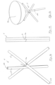
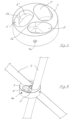
- a frame 1 is shown in the form of a tripod, which here has three rod-shaped legs 2, which are centrally attached to a connecting part 3.
- the frame 1 is unfolded in a use position in which the legs 2 are aligned in a spatial direction, for example to form a fire bowl 1a (cf. Fig. 1 c) in the upper area.
- the fire bowl 1a (or a similar device, such as a lamp or a bucket for cooling drinks, etc.) can also be swiveled as required.
- Fig. 1b The frame 1 is shown in its space-saving transport position, with the three legs 2 folded together in a largely parallel alignment in order to be stacked in a compact manner if necessary.
- Two end surfaces of the legs 2 are provided with reference numerals 2b to indicate quick or screw connections, at which the legs 2 can be extended as required, for example to increase the installation height.
- the fire bowl can thus be folded up according to Fig. 1c
- the quick or screw connection 2b can also be arranged closer to the connecting part 3, as in Fig. 1c indicated in dashed lines. This allows the legs 2 to be moved in the transport position according to Fig. 1 b shortened in order to achieve smaller packing dimensions.
- the partial legs 2 can also be made of wooden rods or plastic tubes, while the central area is generally made of metal for stability reasons.
- two concavely curved support surfaces 5, 5' are provided on the connecting part 3 or the (three) legs 2, to which the outer surface of the legs 2 can alternately cling in the use position, whereby the surface pressure on these contact surfaces is significantly reduced and the frame 1 can therefore bear high loads.
- the (convex) outer surfaces of the tubular legs 2 rest in a similarly shaped, concave bearing surface 5a and are thus positioned.
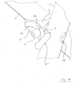
- the locking into the use position is carried out by rotating the legs 2, here around radially aligned pins 4, which are each arranged between the rounded support surfaces 5 and 5', preferably adjacent to the aforementioned locking lugs 5b (see also Fig. 6 ).
- the legs 2 (here the front leg is omitted for a better representation of the pin 4) are preferably made of light metal tubes, as shown in light shade.
- the tubular legs 2 can be stiffened in the area of the connecting part 3, in particular with a metal insert 2a or a bushing (cf. Fig. 5 ). Screw bolts 4a (see also Fig.
- the connecting part 3 is preferably manufactured as a metal casting, in particular together with radially aligned pins 4 or similar connecting elements, as in Fig. 4 shown in a slightly different perspective.
- Fig. 4 The transition between the concave roundings is also visible, as is the locking lug 5b located between them, which is shaped like a gusset in order to be able to be locked in the use position ( Fig. 1a ), but also in the transport position ( Fig. 1 b) to form a "positioning stop" for the pipe surface adjacent there.
- This ensures exact positioning for the legs 2 and a precise fit either on the bearing surface 5a or in the (upper) support surface 5 depending on the desired position (according to Fig. 1a or Fig. 1b ).
- the rod or leg surface In the use position, however, the rod or leg surface not only touches the upper support surface 5, but also the lower support surface 5', which is arranged rotationally symmetrically to the axis of the pin 4. This significantly reduces the surface pressure and increases the load-bearing capacity.
- the upper support surface 5 extends from approximately 0 o'clock to 3 o'clock, like a clock face, and the lower support surface 5' from approximately 6 o'clock to 9 o'clock.
- the leg surface fits perfectly against the correspondingly rounded support surface 5'.
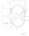
- a cross-section through a tubular leg 2 at the level of the connecting part 3 is shown, the cut surface being determined by the inclined orientation of the leg (corresponding to Fig. 1a ) appears elliptical.
- the leg cross-section is not limited to a cylindrical shape, but can also be elliptical or polygonal, in which case the shape of the support surfaces 5, 5' is adapted accordingly.
- a spring 4c (in particular a disc spring) is arranged between the pin 4 and the screw bolt 4a, so that the outer surface of the leg 2 slides more easily over the locking lug 5b at the transition between the bearing surface 5a and the support surface 5 (or vice versa).
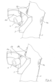
- Fig. 6 Two alternatives to the previously described gusset shape of the locking lug 5b between the support surfaces 5 and 5a are shown.
- the locking lug 5b is parallel to the legs 3 in the transport position (cf. Fig. 1 b) while in the lower part of the drawing the alignment is parallel to the legs 3 in the use position ( Fig. 1a or 1c ) is designed.
- the central connecting part 3 is designed to be open radially outwards, so that the legs 2 can be mounted particularly easily, i.e. they do not have to be threaded in like rings.
- this open design offers an attractive appearance (cf. Fig. 1 a-1c ), since the central connecting part 3 is barely visible.
- the open, star-shaped design offers significant advantages in production compared to a ring shape.
- the support surfaces 5, 5' can be machined with high precision on a CNC milling center, in particular together with the pins 4 in one operation. Grinding heads with radial feed (feed from the outside) can also be used in order to manufacture the support surfaces 5, 5' with high precision in the sense of an optimized system (“snuggling") and thus low surface pressure, which is hardly possible with ring shapes with poor accessibility.
Landscapes
- Engineering & Computer Science (AREA)
- General Engineering & Computer Science (AREA)
- Mechanical Engineering (AREA)
- Furniture Connections (AREA)
- Tables And Desks Characterized By Structural Shape (AREA)
- Devices For Warming Or Keeping Food Or Tableware Hot (AREA)
- Legs For Furniture In General (AREA)
- Special Chairs (AREA)
- Mutual Connection Of Rods And Tubes (AREA)
- Forms Removed On Construction Sites Or Auxiliary Members Thereof (AREA)
Claims (14)
- Râtelier, en particulier sous la forme d'un trépied, avec plusieurs jambes (2) en forme de tige, qui sont fixées de manière centrale à une pièce de liaison (3) conçue de manière ouverte radialement vers l'extérieur, de sorte que les jambes (2) ne doivent pas être enfilées comme pour des anneaux, dans lequel le râtelier peut être replié dans une position de transport peu encombrante, dans laquelle les jambes (2) sont orientées de manière largement parallèle, ainsi que le râtelier peut être déplié dans une position d'utilisation, dans laquelle les jambes (2) sont orientées de manière entrelacée,
caractérisé en ce que
entre les jambes (2) sont disposées deux surfaces d'appui (5, 5') arrondies de manière concave par jambe pour l'appui à plat de la surface de jambe, qui, en position d'utilisation, touchent à plat de manière opposée l'une à l'autre la surface de jambe respective. - Râtelier selon la revendication 1, caractérisé en ce que les surfaces d'appui (5, 5') sont formées respectivement à la pièce de liaison (3).
- Râtelier selon la revendication 1, caractérisé en ce que les surfaces d'appui (5, 5') sont formées respectivement aux jambes (2).
- Râtelier selon l'une des revendications 1 à 3, caractérisé en ce que les surfaces d'appui (5, 5') sont adjacentes l'une à l'autre.
- Râtelier selon l'une des revendications 1 à 4, caractérisé en ce qu'entre les surfaces d'appui (5, 5') est disposé respectivement un tourillon (4) qui est de préférence orienté radialement.
- Râtelier selon l'une des revendications 1 à 5, caractérisé en ce que plusieurs jambes tubulaires (2), en particulier en métal léger, sont disposées à la pièce de liaison (3).
- Râtelier selon l'une des revendications 1 à 6, caractérisé en ce que les jambes (2) sont raidies au niveau de la pièce de liaison (3), en particulier par un insert métallique (2a), une douille ou une pièce intermédiaire.
- Râtelier selon l'une des revendications 1 à 7, caractérisé en ce que des boulons filetés (4a) peuvent être vissés dans les jambes (2) depuis l'extérieur, en particulier avec une tête plate (4b) dans une disposition largement affleurante.
- Râtelier selon la revendication 8, caractérisé en ce qu'un ressort (4c), en particulier une rondelle-ressort, est disposé au boulon fileté (4a).
- Râtelier selon l'une des revendications 1 à 9, caractérisé en ce que la pièce de liaison (3) est formée comme une pièce coulée en métal.
- Râtelier selon l'une des revendications 1 à 10, caractérisé en ce que dans la partie supérieure, au-dessus de la pièce de liaison (3), un gril ou une vasque à feu (1a) peut être inséré, ou un siège, une table ou un seau, en particulier un seau à plantes ou un seau réfrigéré pour boissons, ou un luminaire, en particulier une boule lumineuse, est disposé dans la partie supérieure.
- Râtelier selon l'une des revendications 1 à 11, caractérisé en ce qu'entre les surfaces d'appui (5, 5') et une surface de stockage (5a) un ergot d'encliquetage (5b) est formé qui a de préférence une forme de gousset ou qui est orienté respectivement parallèlement aux jambes (2) en position de transport (Fig. 1 b) ou respectivement parallèlement aux jambes (3) en position d'utilisation (Fig. 1 a).
- Râtelier selon l'une des revendications 1 à 11, caractérisé en ce que les jambes (2) sont formées de plusieurs parties, en particulier peuvent être rallongées avec des liaisons rapides ou vissées (2b).
- Râtelier selon l'une des revendications 1 à 11, caractérisé en ce que la surface de jambe présente une résistance à la pression différente, en particulier est conçue de manière plus souple vers le centre de la pièce de liaison (3).
Applications Claiming Priority (2)
| Application Number | Priority Date | Filing Date | Title |
|---|---|---|---|
| DE202018004631.0U DE202018004631U1 (de) | 2018-10-06 | 2018-10-06 | Gestell, insbesondere in Form eines Dreibeins |
| PCT/EP2019/000288 WO2020069772A1 (fr) | 2018-10-06 | 2019-10-06 | Support, en particulier sous la forme d'un trépied |
Publications (4)
| Publication Number | Publication Date |
|---|---|
| EP3860404A1 EP3860404A1 (fr) | 2021-08-11 |
| EP3860404B1 true EP3860404B1 (fr) | 2025-02-19 |
| EP3860404C0 EP3860404C0 (fr) | 2025-02-19 |
| EP3860404B8 EP3860404B8 (fr) | 2025-03-26 |
Family
ID=68337108
Family Applications (1)
| Application Number | Title | Priority Date | Filing Date |
|---|---|---|---|
| EP19794093.5A Active EP3860404B8 (fr) | 2018-10-06 | 2019-10-06 | Support, en particulier sous la forme d'un trépied |
Country Status (11)
| Country | Link |
|---|---|
| US (1) | US12038126B2 (fr) |
| EP (1) | EP3860404B8 (fr) |
| JP (1) | JP7425789B2 (fr) |
| KR (1) | KR102758817B1 (fr) |
| CN (1) | CN112930131B (fr) |
| AU (1) | AU2019353578A1 (fr) |
| CA (1) | CA3112217A1 (fr) |
| DE (1) | DE202018004631U1 (fr) |
| MX (1) | MX2021003697A (fr) |
| WO (1) | WO2020069772A1 (fr) |
| ZA (1) | ZA202101971B (fr) |
Families Citing this family (8)
| Publication number | Priority date | Publication date | Assignee | Title |
|---|---|---|---|---|
| DE202019000609U1 (de) * | 2019-02-08 | 2020-02-12 | Thomas Kaiser | Feuerschale |
| TWI730881B (zh) * | 2020-08-25 | 2021-06-11 | 永朔實業有限公司 | 連動開收裝置及具有連動開收裝置的椅子 |
| US11965349B2 (en) * | 2020-09-11 | 2024-04-23 | Madi, Llc | Pole cradle |
| JP7752859B2 (ja) * | 2021-11-01 | 2025-10-14 | プラス株式会社 | 三脚連結固定具及び三脚の連結固定方法 |
| CN113914238B (zh) * | 2021-11-11 | 2024-06-11 | 北京市高速公路交通工程有限公司 | 一种用于高速路的高效吸声降噪屏障 |
| TWM631295U (zh) * | 2022-06-17 | 2022-08-21 | 林應安 | 組合桌 |
| USD1019182S1 (en) * | 2023-10-27 | 2024-03-26 | Yueyang County Zhaohang E-Commerce Co., Ltd. | Plant stand |
| USD1088949S1 (en) * | 2025-01-30 | 2025-08-19 | Putian Zhannuo Trading Co., Ltd. | Plant stem support |
Family Cites Families (40)
| Publication number | Priority date | Publication date | Assignee | Title |
|---|---|---|---|---|
| US549457A (en) * | 1895-11-05 | Half to william ii | ||
| US564129A (en) * | 1896-07-14 | Camp-stool | ||
| US948533A (en) * | 1908-08-20 | 1910-02-08 | Charles H Temple | Foldable stool or table. |
| US1172439A (en) * | 1914-07-07 | 1916-02-22 | Elizabeth Crozier | Camp-stool. |
| US1241987A (en) * | 1917-03-06 | 1917-10-02 | Stephen Kalisz | Collapsible stand and support. |
| US1371263A (en) * | 1919-07-16 | 1921-03-15 | Evan L Reed | Tripod support |
| US1561371A (en) * | 1923-01-22 | 1925-11-10 | Leedy Mfg Company | Adjustable stand |
| US1715559A (en) * | 1926-09-04 | 1929-06-04 | Ralph B Long | Folding stool |
| US1940565A (en) * | 1932-05-24 | 1933-12-19 | Cincinnati Galvanizing Company | Collapsible stand |
| US2759780A (en) * | 1952-02-29 | 1956-08-21 | Jr Guy Barker | Collapsible crossed legs table support |
| US3512813A (en) * | 1968-12-09 | 1970-05-19 | Torsten Brimberg | Rod coupling |
| US3709167A (en) | 1971-02-25 | 1973-01-09 | Doering A Mfg Corp | Folding stool |
| DE2163857A1 (de) | 1971-12-22 | 1973-06-28 | Rudolf Schmid | Klappstuhl |
| US4027988A (en) * | 1975-10-28 | 1977-06-07 | Dong Woo Kum | Joint connector for bars |
| JPS53150601U (fr) * | 1977-04-30 | 1978-11-27 | ||
| CH668104A5 (de) * | 1984-11-28 | 1988-11-30 | Paul H Hirzel | Verbindungsanordnung fuer streben. |
| US4934638A (en) * | 1988-02-10 | 1990-06-19 | Davis Kevin R | Collapsible tripod stool |
| US5029795A (en) * | 1989-08-11 | 1991-07-09 | Dexter Ronald P | Camera support stand |
| GB2240919A (en) * | 1990-02-15 | 1991-08-21 | Shui Chuan Chen | Folding seat or table |
| JPH06245840A (ja) * | 1993-02-23 | 1994-09-06 | Kondo Kinzoku:Kk | 脚装置 |
| US5551178A (en) * | 1995-01-19 | 1996-09-03 | Flexsign Inc. | Collapsible sign |
| DE29609996U1 (de) * | 1996-06-08 | 1996-10-31 | Gaiser, Tobias, 72768 Reutlingen | Dreibein-Camping-Stuhl |
| US5876091A (en) * | 1997-03-15 | 1999-03-02 | Chernomashentsev; Alan | Collapsible tripod stool |
| US5851052A (en) * | 1997-10-22 | 1998-12-22 | Gustafsson; Mats | Foldable stool |
| US5975626A (en) * | 1998-07-17 | 1999-11-02 | Tofasco Of America Inc. | Cross-member supporter for foldable furniture |
| US6182650B1 (en) * | 1999-06-18 | 2001-02-06 | Ted A. Tuttle | Dutch oven stand and lid holder |
| US6311857B1 (en) * | 1999-07-09 | 2001-11-06 | Omar Al-Darraji | Stand using hockey stick supports |
| JP3113479U (ja) | 2005-06-08 | 2005-09-08 | コーア株式会社 | 脚の開閉構造 |
| US7367617B1 (en) * | 2006-01-05 | 2008-05-06 | Barry Bond | Collapsible pocket chair |
| US20070196196A1 (en) * | 2006-02-23 | 2007-08-23 | Schorling Detlef T | High strength fastener system |
| US7401850B2 (en) * | 2006-03-14 | 2008-07-22 | Micheel Thomas G | Locking device for collapsible seat |
| US7384097B2 (en) * | 2006-04-28 | 2008-06-10 | Frederick K. Park | Collapsible support frame for furniture |
| TWI337237B (en) * | 2007-12-26 | 2011-02-11 | Rexon Ind Corp Ltd | Collapsible supporting stand |
| GB0911983D0 (en) * | 2009-07-10 | 2009-08-19 | Castle Kate E | Portable toilet apparatus |
| US8448270B2 (en) * | 2010-01-26 | 2013-05-28 | Globe Union Industrial Corp. | Movable support seat for a shower head |
| US8444097B2 (en) * | 2011-07-25 | 2013-05-21 | Morrow Sports, Llc | Support stand |
| US8720896B2 (en) * | 2011-12-13 | 2014-05-13 | Bradley S. Matthis | Portable archery target support |
| US20150056002A1 (en) * | 2013-08-22 | 2015-02-26 | Jeffrey Michael Olds | Apparatus for connecting a plurality of elongate members to form a support structure |
| US9402467B2 (en) * | 2014-05-06 | 2016-08-02 | Zhejiang Hengfeng Top Leisure Co., Ltd. | Collapsible table and method of adjusting the same |
| US10533358B2 (en) * | 2015-09-24 | 2020-01-14 | Sugatsune Kogyo Co., Ltd. | Hinge |
-
2018
- 2018-10-06 DE DE202018004631.0U patent/DE202018004631U1/de active Active
-
2019
- 2019-10-06 AU AU2019353578A patent/AU2019353578A1/en not_active Abandoned
- 2019-10-06 WO PCT/EP2019/000288 patent/WO2020069772A1/fr not_active Ceased
- 2019-10-06 CA CA3112217A patent/CA3112217A1/fr active Pending
- 2019-10-06 CN CN201980065661.3A patent/CN112930131B/zh active Active
- 2019-10-06 EP EP19794093.5A patent/EP3860404B8/fr active Active
- 2019-10-06 JP JP2021518904A patent/JP7425789B2/ja active Active
- 2019-10-06 US US17/278,836 patent/US12038126B2/en active Active
- 2019-10-06 KR KR1020217008113A patent/KR102758817B1/ko active Active
- 2019-10-06 MX MX2021003697A patent/MX2021003697A/es unknown
-
2021
- 2021-03-24 ZA ZA2021/01971A patent/ZA202101971B/en unknown
Also Published As
| Publication number | Publication date |
|---|---|
| AU2019353578A1 (en) | 2021-05-06 |
| US12038126B2 (en) | 2024-07-16 |
| EP3860404B8 (fr) | 2025-03-26 |
| KR102758817B1 (ko) | 2025-01-21 |
| DE202018004631U1 (de) | 2019-10-09 |
| CN112930131A (zh) | 2021-06-08 |
| KR20210071961A (ko) | 2021-06-16 |
| ZA202101971B (en) | 2022-07-27 |
| EP3860404A1 (fr) | 2021-08-11 |
| MX2021003697A (es) | 2021-06-04 |
| JP2022512624A (ja) | 2022-02-07 |
| WO2020069772A1 (fr) | 2020-04-09 |
| EP3860404C0 (fr) | 2025-02-19 |
| US20220034447A1 (en) | 2022-02-03 |
| CA3112217A1 (fr) | 2020-04-09 |
| CN112930131B (zh) | 2024-08-20 |
| JP7425789B2 (ja) | 2024-01-31 |
Similar Documents
| Publication | Publication Date | Title |
|---|---|---|
| EP3860404B1 (fr) | Support, en particulier sous la forme d'un trépied | |
| EP2910146B1 (fr) | Châssis de meuble, notamment châssis de chaise ou de table, et chaise ou table dotée d'un tel châssis de meuble | |
| DE2410099C2 (de) | Zusammensetzbares Untergestell für Möbel | |
| EP3001929B1 (fr) | Table pliante | |
| DE602004007956T2 (de) | Selbststabilisierende stützanordnung für ein möbelstück | |
| EP0641532B1 (fr) | Colonne ajustable en longueur pour chaises, tables ou similaires | |
| EP0663164B1 (fr) | Meuble muni d'un plateau fixe et d'au moins deux plateaux supplémentaires | |
| AT223340B (de) | Stapelbarer Stuhl | |
| EP1604589B1 (fr) | Dispositif de réglage de la hauteur d'une table | |
| WO2004111472A1 (fr) | Table | |
| EP0210585B1 (fr) | Dispositif de support et de réglage pour le siège et le dossier d'une chaise de travail | |
| DE2813199A1 (de) | Freitragende treppe mit einem mittelholm, der aus einzelnen elementen besteht | |
| DE3920959C2 (fr) | ||
| EP3248508B1 (fr) | Dispositif de siège | |
| EP0252170A1 (fr) | Chaise télescopique | |
| DE10051397B4 (de) | Zerlegbares Möbelstück | |
| DE102004043192B4 (de) | Tisch | |
| DE1893258U (de) | Fussteil fuer sitzmoebel. | |
| CH687663A5 (de) | Tisch. | |
| DE102009014141A1 (de) | Rahmen | |
| DE102010060191A1 (de) | Tisch mit einklappbaren Tischbeinen | |
| EP3236088B1 (fr) | Élément de meuble ayant une équerre d'assemblage | |
| EP4663428A1 (fr) | Roulette pivotante | |
| DE19743596C3 (de) | Tisch mit einer Tischplatte | |
| DE102016006307A1 (de) | Platzsparender Drehtisch |
Legal Events
| Date | Code | Title | Description |
|---|---|---|---|
| STAA | Information on the status of an ep patent application or granted ep patent |
Free format text: STATUS: UNKNOWN |
|
| STAA | Information on the status of an ep patent application or granted ep patent |
Free format text: STATUS: THE INTERNATIONAL PUBLICATION HAS BEEN MADE |
|
| PUAI | Public reference made under article 153(3) epc to a published international application that has entered the european phase |
Free format text: ORIGINAL CODE: 0009012 |
|
| STAA | Information on the status of an ep patent application or granted ep patent |
Free format text: STATUS: REQUEST FOR EXAMINATION WAS MADE |
|
| 17P | Request for examination filed |
Effective date: 20210324 |
|
| AK | Designated contracting states |
Kind code of ref document: A1 Designated state(s): AL AT BE BG CH CY CZ DE DK EE ES FI FR GB GR HR HU IE IS IT LI LT LU LV MC MK MT NL NO PL PT RO RS SE SI SK SM TR |
|
| DAV | Request for validation of the european patent (deleted) | ||
| DAX | Request for extension of the european patent (deleted) | ||
| STAA | Information on the status of an ep patent application or granted ep patent |
Free format text: STATUS: EXAMINATION IS IN PROGRESS |
|
| 17Q | First examination report despatched |
Effective date: 20230530 |
|
| GRAP | Despatch of communication of intention to grant a patent |
Free format text: ORIGINAL CODE: EPIDOSNIGR1 |
|
| STAA | Information on the status of an ep patent application or granted ep patent |
Free format text: STATUS: GRANT OF PATENT IS INTENDED |
|
| INTG | Intention to grant announced |
Effective date: 20240923 |
|
| GRAS | Grant fee paid |
Free format text: ORIGINAL CODE: EPIDOSNIGR3 |
|
| GRAA | (expected) grant |
Free format text: ORIGINAL CODE: 0009210 |
|
| STAA | Information on the status of an ep patent application or granted ep patent |
Free format text: STATUS: THE PATENT HAS BEEN GRANTED |
|
| AK | Designated contracting states |
Kind code of ref document: B1 Designated state(s): AL AT BE BG CH CY CZ DE DK EE ES FI FR GB GR HR HU IE IS IT LI LT LU LV MC MK MT NL NO PL PT RO RS SE SI SK SM TR |
|
| REG | Reference to a national code |
Ref country code: GB Ref legal event code: FG4D Free format text: NOT ENGLISH |
|
| REG | Reference to a national code |
Ref country code: CH Ref legal event code: PK Free format text: BERICHTIGUNG B8 Ref country code: CH Ref legal event code: EP |
|
| RAP4 | Party data changed (patent owner data changed or rights of a patent transferred) |
Owner name: WASSERMANN, CHRISTIAN Owner name: KAISER, THOMAS |
|
| RIN2 | Information on inventor provided after grant (corrected) |
Inventor name: WASSERMANN, CHRISTIAN Inventor name: KAISER, THOMAS |
|
| REG | Reference to a national code |
Ref country code: DE Ref legal event code: R096 Ref document number: 502019012969 Country of ref document: DE |
|
| REG | Reference to a national code |
Ref country code: IE Ref legal event code: FG4D Free format text: LANGUAGE OF EP DOCUMENT: GERMAN |
|
| U01 | Request for unitary effect filed |
Effective date: 20250314 |
|
| U07 | Unitary effect registered |
Designated state(s): AT BE BG DE DK EE FI FR IT LT LU LV MT NL PT RO SE SI Effective date: 20250321 |
|
| REG | Reference to a national code |
Ref country code: CH Ref legal event code: PK Free format text: BERICHTIGUNGEN |
|
| RAP2 | Party data changed (patent owner data changed or rights of a patent transferred) |
Owner name: FIRE FRIENDS GMBH & CO. KG |
|
| RIN2 | Information on inventor provided after grant (corrected) |
Inventor name: WASSERMANN, CHRISTIAN Inventor name: KAISER, THOMAS |
|
| U1K | Transfer of rights of the unitary patent after the registration of the unitary effect |
Owner name: FIRE FRIENDS GMBH & CO. KG; DE |
|
| PG25 | Lapsed in a contracting state [announced via postgrant information from national office to epo] |
Ref country code: RS Free format text: LAPSE BECAUSE OF FAILURE TO SUBMIT A TRANSLATION OF THE DESCRIPTION OR TO PAY THE FEE WITHIN THE PRESCRIBED TIME-LIMIT Effective date: 20250519 |
|
| PG25 | Lapsed in a contracting state [announced via postgrant information from national office to epo] |
Ref country code: PL Free format text: LAPSE BECAUSE OF FAILURE TO SUBMIT A TRANSLATION OF THE DESCRIPTION OR TO PAY THE FEE WITHIN THE PRESCRIBED TIME-LIMIT Effective date: 20250219 |
|
| PG25 | Lapsed in a contracting state [announced via postgrant information from national office to epo] |
Ref country code: ES Free format text: LAPSE BECAUSE OF FAILURE TO SUBMIT A TRANSLATION OF THE DESCRIPTION OR TO PAY THE FEE WITHIN THE PRESCRIBED TIME-LIMIT Effective date: 20250219 |
|
| PG25 | Lapsed in a contracting state [announced via postgrant information from national office to epo] |
Ref country code: NO Free format text: LAPSE BECAUSE OF FAILURE TO SUBMIT A TRANSLATION OF THE DESCRIPTION OR TO PAY THE FEE WITHIN THE PRESCRIBED TIME-LIMIT Effective date: 20250519 Ref country code: IS Free format text: LAPSE BECAUSE OF FAILURE TO SUBMIT A TRANSLATION OF THE DESCRIPTION OR TO PAY THE FEE WITHIN THE PRESCRIBED TIME-LIMIT Effective date: 20250619 |
|
| PG25 | Lapsed in a contracting state [announced via postgrant information from national office to epo] |
Ref country code: HR Free format text: LAPSE BECAUSE OF FAILURE TO SUBMIT A TRANSLATION OF THE DESCRIPTION OR TO PAY THE FEE WITHIN THE PRESCRIBED TIME-LIMIT Effective date: 20250219 |
|
| PG25 | Lapsed in a contracting state [announced via postgrant information from national office to epo] |
Ref country code: GR Free format text: LAPSE BECAUSE OF FAILURE TO SUBMIT A TRANSLATION OF THE DESCRIPTION OR TO PAY THE FEE WITHIN THE PRESCRIBED TIME-LIMIT Effective date: 20250520 |
|
| REG | Reference to a national code |
Ref country code: GB Ref legal event code: 732E Free format text: REGISTERED BETWEEN 20250717 AND 20250723 |
|
| PG25 | Lapsed in a contracting state [announced via postgrant information from national office to epo] |
Ref country code: SM Free format text: LAPSE BECAUSE OF FAILURE TO SUBMIT A TRANSLATION OF THE DESCRIPTION OR TO PAY THE FEE WITHIN THE PRESCRIBED TIME-LIMIT Effective date: 20250219 |
|
| PG25 | Lapsed in a contracting state [announced via postgrant information from national office to epo] |
Ref country code: CZ Free format text: LAPSE BECAUSE OF FAILURE TO SUBMIT A TRANSLATION OF THE DESCRIPTION OR TO PAY THE FEE WITHIN THE PRESCRIBED TIME-LIMIT Effective date: 20250219 |
|
| PG25 | Lapsed in a contracting state [announced via postgrant information from national office to epo] |
Ref country code: SK Free format text: LAPSE BECAUSE OF FAILURE TO SUBMIT A TRANSLATION OF THE DESCRIPTION OR TO PAY THE FEE WITHIN THE PRESCRIBED TIME-LIMIT Effective date: 20250219 |
|
| REG | Reference to a national code |
Ref country code: CH Ref legal event code: U11 Free format text: ST27 STATUS EVENT CODE: U-0-0-U10-U11 (AS PROVIDED BY THE NATIONAL OFFICE) Effective date: 20251101 |
|
| U20 | Renewal fee for the european patent with unitary effect paid |
Year of fee payment: 7 Effective date: 20251030 |
|
| PLBE | No opposition filed within time limit |
Free format text: ORIGINAL CODE: 0009261 |
|
| STAA | Information on the status of an ep patent application or granted ep patent |
Free format text: STATUS: NO OPPOSITION FILED WITHIN TIME LIMIT |
|
| PGFP | Annual fee paid to national office [announced via postgrant information from national office to epo] |
Ref country code: GB Payment date: 20251017 Year of fee payment: 7 |
|
| PGFP | Annual fee paid to national office [announced via postgrant information from national office to epo] |
Ref country code: CH Payment date: 20251101 Year of fee payment: 7 |
|
| 26N | No opposition filed |
Effective date: 20251120 |