EP3860876B1 - Systèmes, appareils et procédés pour charger de multiples véhicules à proximité immédiate - Google Patents
Systèmes, appareils et procédés pour charger de multiples véhicules à proximité immédiate Download PDFInfo
- Publication number
- EP3860876B1 EP3860876B1 EP20741012.7A EP20741012A EP3860876B1 EP 3860876 B1 EP3860876 B1 EP 3860876B1 EP 20741012 A EP20741012 A EP 20741012A EP 3860876 B1 EP3860876 B1 EP 3860876B1
- Authority
- EP
- European Patent Office
- Prior art keywords
- battery
- charging
- vehicle
- vehicles
- charge
- Prior art date
- Legal status (The legal status is an assumption and is not a legal conclusion. Google has not performed a legal analysis and makes no representation as to the accuracy of the status listed.)
- Active
Links
Images



Classifications
-
- B—PERFORMING OPERATIONS; TRANSPORTING
- B60—VEHICLES IN GENERAL
- B60L—PROPULSION OF ELECTRICALLY-PROPELLED VEHICLES; SUPPLYING ELECTRIC POWER FOR AUXILIARY EQUIPMENT OF ELECTRICALLY-PROPELLED VEHICLES; ELECTRODYNAMIC BRAKE SYSTEMS FOR VEHICLES IN GENERAL; MAGNETIC SUSPENSION OR LEVITATION FOR VEHICLES; MONITORING OPERATING VARIABLES OF ELECTRICALLY-PROPELLED VEHICLES; ELECTRIC SAFETY DEVICES FOR ELECTRICALLY-PROPELLED VEHICLES
- B60L53/00—Methods of charging batteries, specially adapted for electric vehicles; Charging stations or on-board charging equipment therefor; Exchange of energy storage elements in electric vehicles
- B60L53/10—Methods of charging batteries, specially adapted for electric vehicles; Charging stations or on-board charging equipment therefor; Exchange of energy storage elements in electric vehicles characterised by the energy transfer between the charging station and the vehicle
- B60L53/14—Conductive energy transfer
-
- B—PERFORMING OPERATIONS; TRANSPORTING
- B60—VEHICLES IN GENERAL
- B60L—PROPULSION OF ELECTRICALLY-PROPELLED VEHICLES; SUPPLYING ELECTRIC POWER FOR AUXILIARY EQUIPMENT OF ELECTRICALLY-PROPELLED VEHICLES; ELECTRODYNAMIC BRAKE SYSTEMS FOR VEHICLES IN GENERAL; MAGNETIC SUSPENSION OR LEVITATION FOR VEHICLES; MONITORING OPERATING VARIABLES OF ELECTRICALLY-PROPELLED VEHICLES; ELECTRIC SAFETY DEVICES FOR ELECTRICALLY-PROPELLED VEHICLES
- B60L53/00—Methods of charging batteries, specially adapted for electric vehicles; Charging stations or on-board charging equipment therefor; Exchange of energy storage elements in electric vehicles
- B60L53/50—Charging stations characterised by energy-storage or power-generation means
- B60L53/53—Batteries
-
- B—PERFORMING OPERATIONS; TRANSPORTING
- B60—VEHICLES IN GENERAL
- B60L—PROPULSION OF ELECTRICALLY-PROPELLED VEHICLES; SUPPLYING ELECTRIC POWER FOR AUXILIARY EQUIPMENT OF ELECTRICALLY-PROPELLED VEHICLES; ELECTRODYNAMIC BRAKE SYSTEMS FOR VEHICLES IN GENERAL; MAGNETIC SUSPENSION OR LEVITATION FOR VEHICLES; MONITORING OPERATING VARIABLES OF ELECTRICALLY-PROPELLED VEHICLES; ELECTRIC SAFETY DEVICES FOR ELECTRICALLY-PROPELLED VEHICLES
- B60L53/00—Methods of charging batteries, specially adapted for electric vehicles; Charging stations or on-board charging equipment therefor; Exchange of energy storage elements in electric vehicles
- B60L53/50—Charging stations characterised by energy-storage or power-generation means
- B60L53/57—Charging stations without connection to power networks
-
- B—PERFORMING OPERATIONS; TRANSPORTING
- B60—VEHICLES IN GENERAL
- B60L—PROPULSION OF ELECTRICALLY-PROPELLED VEHICLES; SUPPLYING ELECTRIC POWER FOR AUXILIARY EQUIPMENT OF ELECTRICALLY-PROPELLED VEHICLES; ELECTRODYNAMIC BRAKE SYSTEMS FOR VEHICLES IN GENERAL; MAGNETIC SUSPENSION OR LEVITATION FOR VEHICLES; MONITORING OPERATING VARIABLES OF ELECTRICALLY-PROPELLED VEHICLES; ELECTRIC SAFETY DEVICES FOR ELECTRICALLY-PROPELLED VEHICLES
- B60L53/00—Methods of charging batteries, specially adapted for electric vehicles; Charging stations or on-board charging equipment therefor; Exchange of energy storage elements in electric vehicles
- B60L53/60—Monitoring or controlling charging stations
- B60L53/66—Data transfer between charging stations and vehicles
-
- G—PHYSICS
- G05—CONTROLLING; REGULATING
- G05D—SYSTEMS FOR CONTROLLING OR REGULATING NON-ELECTRIC VARIABLES
- G05D1/00—Control of position, course, altitude or attitude of land, water, air or space vehicles, e.g. using automatic pilots
- G05D1/02—Control of position or course in two dimensions
- G05D1/021—Control of position or course in two dimensions specially adapted to land vehicles
- G05D1/0212—Control of position or course in two dimensions specially adapted to land vehicles with means for defining a desired trajectory
- G05D1/0217—Control of position or course in two dimensions specially adapted to land vehicles with means for defining a desired trajectory in accordance with energy consumption, time reduction or distance reduction criteria
-
- G—PHYSICS
- G05—CONTROLLING; REGULATING
- G05D—SYSTEMS FOR CONTROLLING OR REGULATING NON-ELECTRIC VARIABLES
- G05D1/00—Control of position, course, altitude or attitude of land, water, air or space vehicles, e.g. using automatic pilots
- G05D1/02—Control of position or course in two dimensions
- G05D1/021—Control of position or course in two dimensions specially adapted to land vehicles
- G05D1/0276—Control of position or course in two dimensions specially adapted to land vehicles using signals provided by a source external to the vehicle
- G05D1/028—Control of position or course in two dimensions specially adapted to land vehicles using signals provided by a source external to the vehicle using a RF signal
-
- G—PHYSICS
- G06—COMPUTING OR CALCULATING; COUNTING
- G06Q—INFORMATION AND COMMUNICATION TECHNOLOGY [ICT] SPECIALLY ADAPTED FOR ADMINISTRATIVE, COMMERCIAL, FINANCIAL, MANAGERIAL OR SUPERVISORY PURPOSES; SYSTEMS OR METHODS SPECIALLY ADAPTED FOR ADMINISTRATIVE, COMMERCIAL, FINANCIAL, MANAGERIAL OR SUPERVISORY PURPOSES, NOT OTHERWISE PROVIDED FOR
- G06Q10/00—Administration; Management
- G06Q10/06—Resources, workflows, human or project management; Enterprise or organisation planning; Enterprise or organisation modelling
- G06Q10/063—Operations research, analysis or management
- G06Q10/0631—Resource planning, allocation, distributing or scheduling for enterprises or organisations
- G06Q10/06315—Needs-based resource requirements planning or analysis
-
- B—PERFORMING OPERATIONS; TRANSPORTING
- B60—VEHICLES IN GENERAL
- B60L—PROPULSION OF ELECTRICALLY-PROPELLED VEHICLES; SUPPLYING ELECTRIC POWER FOR AUXILIARY EQUIPMENT OF ELECTRICALLY-PROPELLED VEHICLES; ELECTRODYNAMIC BRAKE SYSTEMS FOR VEHICLES IN GENERAL; MAGNETIC SUSPENSION OR LEVITATION FOR VEHICLES; MONITORING OPERATING VARIABLES OF ELECTRICALLY-PROPELLED VEHICLES; ELECTRIC SAFETY DEVICES FOR ELECTRICALLY-PROPELLED VEHICLES
- B60L2240/00—Control parameters of input or output; Target parameters
- B60L2240/60—Navigation input
- B60L2240/62—Vehicle position
-
- B—PERFORMING OPERATIONS; TRANSPORTING
- B60—VEHICLES IN GENERAL
- B60L—PROPULSION OF ELECTRICALLY-PROPELLED VEHICLES; SUPPLYING ELECTRIC POWER FOR AUXILIARY EQUIPMENT OF ELECTRICALLY-PROPELLED VEHICLES; ELECTRODYNAMIC BRAKE SYSTEMS FOR VEHICLES IN GENERAL; MAGNETIC SUSPENSION OR LEVITATION FOR VEHICLES; MONITORING OPERATING VARIABLES OF ELECTRICALLY-PROPELLED VEHICLES; ELECTRIC SAFETY DEVICES FOR ELECTRICALLY-PROPELLED VEHICLES
- B60L2240/00—Control parameters of input or output; Target parameters
- B60L2240/60—Navigation input
- B60L2240/62—Vehicle position
- B60L2240/622—Vehicle position by satellite navigation
-
- B—PERFORMING OPERATIONS; TRANSPORTING
- B60—VEHICLES IN GENERAL
- B60L—PROPULSION OF ELECTRICALLY-PROPELLED VEHICLES; SUPPLYING ELECTRIC POWER FOR AUXILIARY EQUIPMENT OF ELECTRICALLY-PROPELLED VEHICLES; ELECTRODYNAMIC BRAKE SYSTEMS FOR VEHICLES IN GENERAL; MAGNETIC SUSPENSION OR LEVITATION FOR VEHICLES; MONITORING OPERATING VARIABLES OF ELECTRICALLY-PROPELLED VEHICLES; ELECTRIC SAFETY DEVICES FOR ELECTRICALLY-PROPELLED VEHICLES
- B60L2250/00—Driver interactions
- B60L2250/16—Driver interactions by display
-
- B—PERFORMING OPERATIONS; TRANSPORTING
- B60—VEHICLES IN GENERAL
- B60L—PROPULSION OF ELECTRICALLY-PROPELLED VEHICLES; SUPPLYING ELECTRIC POWER FOR AUXILIARY EQUIPMENT OF ELECTRICALLY-PROPELLED VEHICLES; ELECTRODYNAMIC BRAKE SYSTEMS FOR VEHICLES IN GENERAL; MAGNETIC SUSPENSION OR LEVITATION FOR VEHICLES; MONITORING OPERATING VARIABLES OF ELECTRICALLY-PROPELLED VEHICLES; ELECTRIC SAFETY DEVICES FOR ELECTRICALLY-PROPELLED VEHICLES
- B60L2260/00—Operating Modes
- B60L2260/40—Control modes
- B60L2260/50—Control modes by future state prediction
- B60L2260/52—Control modes by future state prediction drive range estimation, e.g. of estimation of available travel distance
-
- B—PERFORMING OPERATIONS; TRANSPORTING
- B60—VEHICLES IN GENERAL
- B60L—PROPULSION OF ELECTRICALLY-PROPELLED VEHICLES; SUPPLYING ELECTRIC POWER FOR AUXILIARY EQUIPMENT OF ELECTRICALLY-PROPELLED VEHICLES; ELECTRODYNAMIC BRAKE SYSTEMS FOR VEHICLES IN GENERAL; MAGNETIC SUSPENSION OR LEVITATION FOR VEHICLES; MONITORING OPERATING VARIABLES OF ELECTRICALLY-PROPELLED VEHICLES; ELECTRIC SAFETY DEVICES FOR ELECTRICALLY-PROPELLED VEHICLES
- B60L2260/00—Operating Modes
- B60L2260/40—Control modes
- B60L2260/50—Control modes by future state prediction
- B60L2260/54—Energy consumption estimation
-
- B—PERFORMING OPERATIONS; TRANSPORTING
- B60—VEHICLES IN GENERAL
- B60L—PROPULSION OF ELECTRICALLY-PROPELLED VEHICLES; SUPPLYING ELECTRIC POWER FOR AUXILIARY EQUIPMENT OF ELECTRICALLY-PROPELLED VEHICLES; ELECTRODYNAMIC BRAKE SYSTEMS FOR VEHICLES IN GENERAL; MAGNETIC SUSPENSION OR LEVITATION FOR VEHICLES; MONITORING OPERATING VARIABLES OF ELECTRICALLY-PROPELLED VEHICLES; ELECTRIC SAFETY DEVICES FOR ELECTRICALLY-PROPELLED VEHICLES
- B60L58/00—Methods or circuit arrangements for monitoring or controlling batteries or fuel cells, specially adapted for electric vehicles
- B60L58/10—Methods or circuit arrangements for monitoring or controlling batteries or fuel cells, specially adapted for electric vehicles for monitoring or controlling batteries
- B60L58/12—Methods or circuit arrangements for monitoring or controlling batteries or fuel cells, specially adapted for electric vehicles for monitoring or controlling batteries responding to state of charge [SoC]
-
- G—PHYSICS
- G06—COMPUTING OR CALCULATING; COUNTING
- G06Q—INFORMATION AND COMMUNICATION TECHNOLOGY [ICT] SPECIALLY ADAPTED FOR ADMINISTRATIVE, COMMERCIAL, FINANCIAL, MANAGERIAL OR SUPERVISORY PURPOSES; SYSTEMS OR METHODS SPECIALLY ADAPTED FOR ADMINISTRATIVE, COMMERCIAL, FINANCIAL, MANAGERIAL OR SUPERVISORY PURPOSES, NOT OTHERWISE PROVIDED FOR
- G06Q10/00—Administration; Management
- G06Q10/02—Reservations, e.g. for tickets, services or events
-
- Y—GENERAL TAGGING OF NEW TECHNOLOGICAL DEVELOPMENTS; GENERAL TAGGING OF CROSS-SECTIONAL TECHNOLOGIES SPANNING OVER SEVERAL SECTIONS OF THE IPC; TECHNICAL SUBJECTS COVERED BY FORMER USPC CROSS-REFERENCE ART COLLECTIONS [XRACs] AND DIGESTS
- Y02—TECHNOLOGIES OR APPLICATIONS FOR MITIGATION OR ADAPTATION AGAINST CLIMATE CHANGE
- Y02T—CLIMATE CHANGE MITIGATION TECHNOLOGIES RELATED TO TRANSPORTATION
- Y02T10/00—Road transport of goods or passengers
- Y02T10/60—Other road transportation technologies with climate change mitigation effect
- Y02T10/70—Energy storage systems for electromobility, e.g. batteries
-
- Y—GENERAL TAGGING OF NEW TECHNOLOGICAL DEVELOPMENTS; GENERAL TAGGING OF CROSS-SECTIONAL TECHNOLOGIES SPANNING OVER SEVERAL SECTIONS OF THE IPC; TECHNICAL SUBJECTS COVERED BY FORMER USPC CROSS-REFERENCE ART COLLECTIONS [XRACs] AND DIGESTS
- Y02—TECHNOLOGIES OR APPLICATIONS FOR MITIGATION OR ADAPTATION AGAINST CLIMATE CHANGE
- Y02T—CLIMATE CHANGE MITIGATION TECHNOLOGIES RELATED TO TRANSPORTATION
- Y02T10/00—Road transport of goods or passengers
- Y02T10/60—Other road transportation technologies with climate change mitigation effect
- Y02T10/7072—Electromobility specific charging systems or methods for batteries, ultracapacitors, supercapacitors or double-layer capacitors
-
- Y—GENERAL TAGGING OF NEW TECHNOLOGICAL DEVELOPMENTS; GENERAL TAGGING OF CROSS-SECTIONAL TECHNOLOGIES SPANNING OVER SEVERAL SECTIONS OF THE IPC; TECHNICAL SUBJECTS COVERED BY FORMER USPC CROSS-REFERENCE ART COLLECTIONS [XRACs] AND DIGESTS
- Y02—TECHNOLOGIES OR APPLICATIONS FOR MITIGATION OR ADAPTATION AGAINST CLIMATE CHANGE
- Y02T—CLIMATE CHANGE MITIGATION TECHNOLOGIES RELATED TO TRANSPORTATION
- Y02T10/00—Road transport of goods or passengers
- Y02T10/60—Other road transportation technologies with climate change mitigation effect
- Y02T10/72—Electric energy management in electromobility
-
- Y—GENERAL TAGGING OF NEW TECHNOLOGICAL DEVELOPMENTS; GENERAL TAGGING OF CROSS-SECTIONAL TECHNOLOGIES SPANNING OVER SEVERAL SECTIONS OF THE IPC; TECHNICAL SUBJECTS COVERED BY FORMER USPC CROSS-REFERENCE ART COLLECTIONS [XRACs] AND DIGESTS
- Y02—TECHNOLOGIES OR APPLICATIONS FOR MITIGATION OR ADAPTATION AGAINST CLIMATE CHANGE
- Y02T—CLIMATE CHANGE MITIGATION TECHNOLOGIES RELATED TO TRANSPORTATION
- Y02T90/00—Enabling technologies or technologies with a potential or indirect contribution to GHG emissions mitigation
- Y02T90/10—Technologies relating to charging of electric vehicles
- Y02T90/12—Electric charging stations
-
- Y—GENERAL TAGGING OF NEW TECHNOLOGICAL DEVELOPMENTS; GENERAL TAGGING OF CROSS-SECTIONAL TECHNOLOGIES SPANNING OVER SEVERAL SECTIONS OF THE IPC; TECHNICAL SUBJECTS COVERED BY FORMER USPC CROSS-REFERENCE ART COLLECTIONS [XRACs] AND DIGESTS
- Y02—TECHNOLOGIES OR APPLICATIONS FOR MITIGATION OR ADAPTATION AGAINST CLIMATE CHANGE
- Y02T—CLIMATE CHANGE MITIGATION TECHNOLOGIES RELATED TO TRANSPORTATION
- Y02T90/00—Enabling technologies or technologies with a potential or indirect contribution to GHG emissions mitigation
- Y02T90/10—Technologies relating to charging of electric vehicles
- Y02T90/14—Plug-in electric vehicles
-
- Y—GENERAL TAGGING OF NEW TECHNOLOGICAL DEVELOPMENTS; GENERAL TAGGING OF CROSS-SECTIONAL TECHNOLOGIES SPANNING OVER SEVERAL SECTIONS OF THE IPC; TECHNICAL SUBJECTS COVERED BY FORMER USPC CROSS-REFERENCE ART COLLECTIONS [XRACs] AND DIGESTS
- Y02—TECHNOLOGIES OR APPLICATIONS FOR MITIGATION OR ADAPTATION AGAINST CLIMATE CHANGE
- Y02T—CLIMATE CHANGE MITIGATION TECHNOLOGIES RELATED TO TRANSPORTATION
- Y02T90/00—Enabling technologies or technologies with a potential or indirect contribution to GHG emissions mitigation
- Y02T90/10—Technologies relating to charging of electric vehicles
- Y02T90/16—Information or communication technologies improving the operation of electric vehicles
Definitions
- the apparatus includes a vehicle controller and a mobile battery charging device.
- the controller is structured to communicate information indicative of a status of the battery system of the vehicle over a network.
- the mobile battery charging device includes a drive system, a charging interface, and a mobile battery charging device controller.
- the drive system is structured to propel the mobile battery charging device.
- the charging interface is structured to engage the battery charging port of the vehicle.
- the mobile battery charging device controller is structured to: receive the information of the state of charge of the battery system of the vehicle; determine a position of the vehicle; and command the drive system to move the mobile battery charging device to engage the charging interface with the battery charging port of the vehicle to charge the battery system of the vehicle.
- the mobile battery charging device controller 86 is structured to control the mobile battery charging device 22 to travel to the vehicles 18 and charge the vehicles 18 according to the priority structure. In some embodiments, the mobile battery charging device controller 86 is also structured to receive an amount of battery charge required for an upcoming mission of the vehicle 18. In such an embodiment, the mobile battery charging device controller 86 is structured to determine the priority structure based on the charging priorities of each of the vehicles 18.
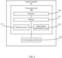
- the positioning circuit 114, the battery status determination circuit 118, and the battery charging circuit 138 are embodied as machine or computer-readable media that is executable by a processor, such as processor 106 or processor 130.
- the machine-readable media facilitates performance of certain operations to enable reception and transmission of data.
- the machine-readable media may provide an instruction (e.g., command, etc.) to, e.g., acquire data.
- the machine-readable media may include programmable logic that defines the frequency of acquisition of the data (or, transmission of the data).
- the memory devices 110, 134 may store data and/or computer code for facilitating the various processes described herein.
- the memory devices 110, 134 may be communicably connected to the processors 106, 130, respectively, to provide computer code or instructions to the processor 68 for executing at least some of the processes described herein.
- the memory devices 110, 134 may be or include tangible, non-transient volatile memory or non-volatile memory. Accordingly, the memory devices 110, 134 may include database components, object code components, script components, or any other type of information structure for supporting the various activities and information structures described herein.
- the communications interfaces 122, 142 may include wired or wireless interfaces (e.g., jacks, antennas, transmitters, receivers, transceivers, wire terminals, etc.) for conducting data communications with various systems, devices, or networks.
- the communications interfaces 122, 142 may include an Ethernet card and port for sending and receiving data via an Ethernet-based communications network and/or a Wi-Fi transceiver for communicating via a wireless communications network.
- the communications interfaces 122, 142 may be structured to communicate via local area networks or wide area networks (e.g., the Internet, etc.) and may use a variety of communications protocols (e.g., IP, LON, Bluetooth, ZigBee, radio, cellular, near field communication, etc.).
- the positioning circuit 114 in response to determining that the position of the vehicle 18 is unacceptable, is structured to notify the operator that the vehicle 18 is in an unacceptable position via the operator I/O device 50.
- the notification may be a visual indication such as a light or a message on a dashboard of the vehicle 18.
- the notification may be an auditory notification.
- the notification may include instructions for correctly positioning the vehicle 18.
- the positioning circuit 114 in response to determining that the position of the vehicle 18 is unacceptable, is structured not to send any notifications to the operator of the vehicle 18 (e.g., the absence of the notification indicates that the vehicle 18 position is unacceptable).
- the battery status determination circuit 118 is structured to send information indicative of the identity of the vehicle 18, the battery status of the battery system 30, the upcoming charge requirement, and/or the information indicative of the position of the vehicle 18 to the controller 86 of the mobile battery charging device 22.
- the battery charging circuit 138 is structured to charge the fleet of vehicles 10 in a sequential order based on the positions of the vehicles 18 in the charging facility 14.
- the mobile battery charging device 22 is structured to command the drive system 82 to follow a path from a starting point to an ending point and charge the battery systems 30 of the vehicles 18 as the mobile battery charging device 22 encounters each of the vehicles 18.
- the drive system 82 is structured to travel along the system of mounted tracks 62
- the system of mounted tracks 62 forms the path.
- the mobile battery charging device controller 86 can be structured to determine the path based on the positions of parking indicators 66 or the path can be programmed into the memory device 134 of the mobile battery charging device 22.
- the battery charging circuit 138 is structured to receive, for each of the vehicles 18, the information indicative of the identity of the vehicle 18 and the battery status of the battery system 30 of the vehicle 18 as the mobile battery charging device 22 approaches each vehicle 18. In some embodiments, the battery charging circuit 138 is structured to determine the amount of battery charge required for the upcoming mission from the vehicle 18. In some embodiments, the battery charging circuit 138 can be structured to retrieve each of the routes that will be travelled by the vehicle 18 on the next mission from the memory device 110 or another database. The battery charging circuit 138 may be structured to determine the upcoming charge requirement based on the amount of battery charge required for the vehicle 18 to complete the upcoming mission.
- the battery charging circuit 118 may be structured to consider on-route charging opportunities in determining the amount of battery charge required for the vehicle 18 to complete the upcoming mission.
- the amount of charge can be a percentage of the total storage capacity of the battery system 30.
- the battery charging circuit 138 is structured to determine a relative position of the charging port 58 of the vehicle 18 and the mobile battery charging device 22 based on information received from the sensors 38, 90.
- the battery charging circuit 138 is structured to command the drive system 82 of the mobile battery charging device 22 to substantially align the mobile battery charging device 22 with the charging port 58 of the vehicle 18.
- the battery charging circuit 138 is then structured to command the charging device drive system 98 to position the charging interface 74 proximate the charging port 58 of the vehicle 18 and engage the charging port 94 of the mobile battery charging device 22 with the charging port 58 of the vehicle 18.
- the battery charging circuit 138 is structured to charge the battery system 30 of the vehicle 18 based on the battery status of the battery system 30.
- the battery charging circuit 138 can receive a notification from the battery status determination circuit 118 of the vehicle 18 indicating that the battery system 30 has been charged according to the upcoming charge requirement and/or has been fully charged.
- the battery charging circuit 138 is structured to command the charging interface drive system 98 to disengage the charging port 58 of the mobile battery charging device 22 from the charging port 58 of the vehicle 18.
- the battery charging circuit 138 is then structured to command the drive system 82 to approach the next vehicle 18 along the path.
- the battery charging circuit 138 is structured to determine a priority structure based on the battery statuses of the battery systems 30 of each of the vehicles 18.
- the battery charging circuit 138 is structured to receive the battery statuses of the battery system 30, the information indicative of the identity of the vehicle 18before determining the priority structure.
- the battery charging circuit 138 can be structured to command the drive system 82 to travel along the path from the starting point to the ending point and receive the battery statuses of the battery system 30 and the information indicative of the identity of the vehicle 18 from each of the vehicles 18 as the mobile battery charging device 22 passes proximate each of the vehicles 18.
- the battery charging circuit 138 is structured to receive the battery status of the battery system 30 and the information indicative of the identity of the vehicle 18 from each of the vehicles 18 as the vehicles 18 enter the charging facility 14 or park in the charging facility 14. In some embodiments, the battery charging circuit 138 is structured to determine a charge time for each of the battery systems 30 of the vehicles 18. In some embodiments, the battery charging circuit 138 is structured to determine the charge time based on the SOCs of the battery system 30 of each of the vehicles 18. In some embodiments, the battery charging circuit 138 is structured to determine the charge time based on the SOCs and the upcoming charge requirements of the battery system 30 of each of the vehicles 18. In some embodiments, the battery charging circuit 138 is structured to consider on-route charging opportunities when determining the amount of battery charge required for the vehicle 18 to complete the upcoming mission.
- the battery charging circuit 138 is structured to determine the charging priority of each of the vehicles 18 based on the battery statuses (e.g., the SOCs of the battery systems 30 of each of the vehicles 18, the amount of battery system 30 charge required) for the each of the vehicles 18 to complete an upcoming mission, and/or the charge times for each of the vehicles 18.
- the battery charging circuit 138 is structured to determine the priority structure of the fleet of vehicles 10 based on the charging priorities of each of the vehicles 18. In some embodiments, the battery charging circuit 138 is structured to determine the priority structure so that the vehicles 18 having the battery systems 30 with the lowest SOC, the vehicles 18 having the battery systems 30 requiring the largest charge to complete the next upcoming mission, and/or the vehicles 18 having the battery systems 30 that require the longest charge time are charged first.
- the battery charging circuit 138 is structured to determine the priority structure so that the vehicles 18 having the battery systems 30 with the highest SOC, the vehicles 18 having the battery systems 30 requiring the least charge to complete the next upcoming mission, and/or the vehicles 18 having the battery systems 30 that require the shortest charge time are charged first.
- the battery charging circuit 138 is structured to retrieve the identity and location of the highest priority vehicle 18 in the priority structure.
- the battery charging circuit 138 is structured to command the drive system 82 to travel to the vehicle 18 having the highest priority.
- the battery charging circuit 138 is structured to charge the battery system 30 of the vehicle 18 as described above.
- the battery charging circuit 138 is structured to determine the identity of the vehicle 18 having the next highest priority according to the priority structure and travel to and charge the next highest priority vehicle 18 as described above until the battery systems 30 of all of the vehicles 18 in the fleet of vehicles 10 have been charged.
- FIG. 4 illustrates an exemplary method 400 for charging the fleet of vehicles 10 with the mobile battery charging device 22 to an example.
- the operator drives one of the vehicles 18 of the fleet of vehicles 10 into the charging facility 14 and parks the vehicle 18 proximate one of the parking indicators 66.
- the positioning circuit 114 receives information indicative of the position of the vehicle 18 relative to the parking indicators 66.
- the positioning circuit 114 can receive the information indicative of the position of the vehicle 18 from the sensors 38 and/or the sensors 70.
- the positioning circuit 114 in response to determining that the position of the vehicle 18 relative to the parking indicators 66 is acceptable, the positioning circuit 114 can notify the operator, via the operator I/O device 50, to indicate that the vehicle 18 position is acceptable.
- the positioning circuit 114 can indicate that the position of the vehicle 18 relative to the parking indicators 66 is unacceptable. For example, the positioning circuit 114 can either not send a notification to the user (e.g., the absence of the notification indicates that the vehicle 18 position is unacceptable) or can send a notification to the operator via the operator I/O device 50 indicating that the vehicle 18 position is unacceptable. In some embodiments, the notification may provide instructions on how to reposition the vehicle 18.
- the battery status determination circuit 118 receives information indicative of the battery status of the battery system 30 of the vehicle 18.
- the information indicative of the SOC of each of the one or more batteries 54 can be determined by at least one battery sensor 90.
- the battery status determination circuit 118 can determine the SOC of the battery system 30 based on the SOCs of the one or more batteries 54.
- the battery status determination circuit 118 may determine the amount of battery charge required for the vehicle 18 to complete the upcoming mission. For example, the battery status determination circuit 118 may retrieve information indicative of the upcoming mission from a networked device and determine the amount of battery charge required for the next mission based on a next route or schedule of routes for the mission and/or on-route charging opportunities during the mission.
- the battery status determination circuit 118 may also determine a charging time for the battery system 30 based on the amount of battery charge required for the next mission and the SOC of the battery system 30. At process 428, the battery status determination circuit 118 sends the information indicative of the status of the battery system 30 and information indicative of the identity of the vehicle 18 to the mobile battery charging device controller 86.
- the battery charging circuit 138 commands the drive system 82 of the mobile battery charging device 22 to follow the path until the mobile battery charging device 22 approaches a first vehicle 18 along the path.
- the drive system 82 is structured to travel along the system of mounted tracks 62
- the system of mounted tracks 62 forms the path.
- the mobile battery charging device controller 86 can be structured to determine the path based on the parking indicators 66 or the path can be programmed into the memory device 134 of the mobile battery charging device 22.
- the battery charging circuit 138 receives the battery status and information indicative of the identity of the vehicle 18.
- the battery charging circuit 138 may determine the amount of battery charge required for the upcoming mission.
- the battery charging circuit 138 may retrieve the amount of battery charge required for the upcoming mission from a database based on the information indicative of the identity of the vehicle 18.
- the battery charging circuit 138 may determine the amount of battery charge required for the upcoming mission based on the route or route(s) the vehicle 18 is scheduled to travel during the upcoming mission.
- the battery charging circuit 138 may also determine a charging time for the battery system 30 based on the amount of battery charge required for the next mission and the SOC of the battery system 30.
- the battery charging circuit 138 sends the information indicative of the status of the battery system 30 and information indicative of the identity of the vehicle 18 to the mobile battery charging device controller 86.
- the battery charging circuit 138 determines a relative position of the charging port 58 of the vehicle 18 and the mobile battery charging device 22.
- the battery charging circuit 138 commands the drive system 82 of the mobile battery charging device 22 to substantially align the mobile battery charging device 22 with the charging port 58 of the vehicle 18.
- the battery charging circuit 138 commands the battery charging interface drive system 98 to position the charging interface 74 proximate the charging port 58 of the vehicle 18 and engage the charging port 94 of the charging interface 74 with the charging port 58 of the vehicle 18.
- the battery charging circuit 138 charges the battery system 30 of the vehicle 18 based on the SOC of the battery system 30 and/or the charge requirement to complete the upcoming mission.
- the battery status determination circuit 118 determines that the battery system 30 is sufficiently charged and sends a notification to the battery charging circuit 138.
- the battery status determination circuit 118 can determine that the battery system 30 is fully charged based on the information indicative of the SOC of the battery system 30 determined by the sensor(s) 42.
- the battery charging circuit 138 commands the charging interface drive system 98 to disengage the charging port 94 of the charging interface 74 from the charging port 58 of the vehicle 18.
- the battery charging circuit 138 commands the drive system 82 to approach the next vehicle 18 along the path.
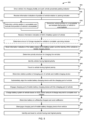
- FIG. 5 is a flow diagram of a method 500 for determining a priority structure for charging the fleet of vehicles 10 with the mobile battery charging device 22 and charging the fleet of vehicles 10 with the mobile battery charging device 22 according to the priority structure according to an embodiment.
- Processes 504 - 516 are substantially similar to processes 404 - 416 of the method 400. Processes 504 - 516 and are shown in FIG. 5 but are not discussed in detail herein for the sake of brevity.
- the battery status determination circuit 118 receives information indicative of the battery status of the battery system 30.
- the information indicative of the SOC of each of the one or more batteries 54 can be determined by at least one battery sensor 42.
- the battery status determination circuit 118 can determine the SOC of the battery system 30 based on the SOCs of the one or more batteries 54.
- the battery status determination circuit 118 may determine the amount of battery charge required for the vehicle 18 to complete the upcoming mission.
- the battery charging circuit 138 may retrieve the amount of battery charge required for the upcoming mission from a database based on the information indicative of the identity of the vehicle 18.
- the battery charging circuit 138 may determine the amount of battery charge required for the upcoming mission based on the route or route(s) the vehicle 18 is scheduled to travel during the upcoming mission.
- the battery status determination circuit 118 may also determine a charging time for the battery system 30 based on the amount of battery charge required for the next mission and the SOC of the battery system 30.
- the battery status determination circuit 118 sends the information indicative of the status of the battery system 30 and information indicative of the identity of the vehicle 18 to the mobile battery charging device controller 86.
- the battery charging circuit 138 determines the priority structure for charging the vehicles 18 of the fleet of vehicles 10. In some embodiments, battery charging circuit 138 determines the priority structure based on the battery statuses (e.g., the SOCs of the battery systems 30, the amount of charge required for the battery system 30 to complete an upcoming mission, and a charge time of the battery systems 30) for each of the vehicles 18.
- the battery charging circuit 138 is structured to identify the vehicle 18 having the highest priority.
- the charging interface 74 commands the drive system 82 of the mobile battery charging device 22 to travel to the vehicle 18 having the highest priority.
- the battery charging circuit 138 determines a relative position of the charging port 58 of the vehicle 18 and the mobile battery charging device 22.
- the battery charging circuit 138 commands the drive system 82 of the mobile battery charging device 22 to substantially align the mobile battery charging device 22 with the charging port 58 of the vehicle 18.
- the battery charging circuit 138 commands the battery charging interface drive system 98 to position the charging interface 74 proximate the charging port 58 of the vehicle 18 and engage the charging port 94 of the charging interface 74 with the charging port 58 of the vehicle 18.
- the battery charging circuit 138 charges the battery system 30 of the vehicle 18 based on the SOC of the battery system 30 and/or the charge requirement to complete the upcoming mission.
- the battery status determination circuit 118 determines that the battery system 30 is sufficiently charged and sends a notification to the battery charging circuit 138.
- the battery status determination circuit 118 can determine that the battery system 30 is fully charged based on the information indicative of the SOC of the battery system 30 determined by the sensor(s) 42.
- the battery charging circuit 138 commands the charging interface drive system 98 to disengage the charging port 94 of the mobile battery charging device 22 from the charging port 58 of the vehicle 18.
- the battery charging circuit 138 identifies the vehicle 18 having the next highest priority.
- the battery charging circuit 138 commands the driving system to approach the next vehicle 18 having the next highest priority according to the priority structure.
- circuit A communicably “coupled” to circuit B may signify that circuit A communicates directly with circuit B (i.e., no intermediary) or communicates indirectly with circuit B (e.g., through one or more intermediaries).
- the vehicle controller 34 or the controller 86 of the mobile battery charging device 22 may include any number of circuits for completing the functions described herein.
- the activities and functionalities of the circuits 114, 118, 122 may be combined in multiple circuits or as a single circuit. Additional circuits with additional functionality may also be included. Further, the controllers 34, 86 may further control other activity beyond the scope of the present disclosure.
- the "circuits" may be implemented in machine-readable medium for execution by various types of processors, such as the processor 106 of FIG. 2 and/or the processor 130 of FIG. 3 .
- An identified circuit of executable code may, for instance, comprise one or more physical or logical blocks of computer instructions, which may, for instance, be organized as an object, procedure, or function. Nevertheless, the executables of an identified circuit need not be physically located together, but may comprise disparate instructions stored in different locations which, when joined logically together, comprise the circuit and achieve the stated purpose for the circuit.
- a circuit of computer readable program code may be a single instruction, or many instructions, and may even be distributed over several different code segments, among different programs, and across several memory devices.
- operational data may be identified and illustrated herein within circuits, and may be embodied in any suitable form and organized within any suitable type of data structure.
- the operational data may be collected as a single data set, or may be distributed over different locations including over different storage devices, and may exist, at least partially, merely as electronic signals on a system or network.
- processor may be implemented as one or more general-purpose processors, application specific integrated circuits (ASICs), field programmable gate arrays (FPGAs), digital signal processors (DSPs), or other suitable electronic data processing components structured to execute instructions provided by memory.
- ASICs application specific integrated circuits
- FPGAs field programmable gate arrays
- DSPs digital signal processors
- the one or more processors may take the form of a single core processor, multi-core processor (e.g., a dual core processor, triple core processor, quad core processor, etc.), microprocessor, etc.
- the one or more processors may be external to the apparatus, for example, the one or more processors may be a remote processor (e.g., a cloud based processor). Alternatively or additionally, the one or more processors may be internal and/or local to the apparatus. In this regard, a given circuit or components thereof may be disposed locally (e.g., as part of a local server, a local computing system, etc.) or remotely (e.g., as part of a remote server such as a cloud based server). To that end, a "circuit" as described herein may include components that are distributed across one or more locations.
Landscapes
- Engineering & Computer Science (AREA)
- Power Engineering (AREA)
- Transportation (AREA)
- Mechanical Engineering (AREA)
- Business, Economics & Management (AREA)
- Human Resources & Organizations (AREA)
- Physics & Mathematics (AREA)
- General Physics & Mathematics (AREA)
- Radar, Positioning & Navigation (AREA)
- Economics (AREA)
- Automation & Control Theory (AREA)
- Strategic Management (AREA)
- Remote Sensing (AREA)
- Aviation & Aerospace Engineering (AREA)
- Entrepreneurship & Innovation (AREA)
- Theoretical Computer Science (AREA)
- Marketing (AREA)
- General Business, Economics & Management (AREA)
- Tourism & Hospitality (AREA)
- Quality & Reliability (AREA)
- Operations Research (AREA)
- Development Economics (AREA)
- Educational Administration (AREA)
- Game Theory and Decision Science (AREA)
- Life Sciences & Earth Sciences (AREA)
- Sustainable Development (AREA)
- Sustainable Energy (AREA)
- Electric Propulsion And Braking For Vehicles (AREA)
- Charge And Discharge Circuits For Batteries Or The Like (AREA)
Claims (12)
- Dispositif de recharge de batterie mobile (22) comprenant :un système d'entraînement (82) conçu pour faire avancer le dispositif de recharge de batterie mobile (22) ;une interface de recharge (74) conçue pour venir en prise avec une prise de recharge (58) d'un véhicule (18) qui est l'un parmi une flotte de véhicules ; etun dispositif de commande (86) conçu pour :recevoir des informations indicatives d'un statut d'un système de batterie (30) de chaque véhicule de la flotte de véhicules, le statut du système de batterie de chaque véhicule de la flotte de véhicules incluant un état de charge du système de batterie et des informations concernant une quantité de charge nécessaire au système de batterie pour réaliser une prochaine mission, la quantité de charge nécessaire au système de batterie pour réaliser la prochaine mission étant un pourcentage de la capacité de stockage totale du système de batterie ;déterminer une priorité de recharge pour chacun des véhicules sur la base de l'état de charge du système de batterie et de la quantité de charge nécessaire au système de batterie pour réaliser la prochaine mission ;recevoir un emplacement du véhicule dont le système de batterie présente la priorité de recharge la plus élevée ;commander au système d'entraînement (82) de déplacer le dispositif de recharge de batterie (22) afin de mettre en prise l'interface de recharge avec la prise de recharge du véhicule dont le système de batterie présente la priorité de recharge la plus élevée pour charger le système de batterie du véhicule sur la base de la charge nécessaire au système de batterie pour réaliser la prochaine mission ;en réponse à la recharge du système de batterie du véhicule sur la base de la réception d'une notification du véhicule dont le système de batterie présente la priorité de recharge la plus élevée recevoir un emplacement d'un second véhicule dont un second système de batterie présente une priorité de recharge la plus élevée suivante ; etcommander au système d'entraînement de désengager l'interface de recharge de la prise de recharge et de déplacer le dispositif de recharge de batterie mobile pour mettre en prise l'interface de recharge avec la prise de recharge du second véhicule dont le second système de batterie présente la priorité de recharge la plus élevée suivante pour charger le second système de batterie du second véhicule.
- Dispositif de recharge de batterie mobile selon la revendication 1, dans lequel la priorité de recharge est basée sur les statuts des systèmes de batterie pour chacun des véhicules.
- Dispositif de recharge de batterie mobile selon la revendication 2, dans lequel le dispositif de commande est conçu pour :déterminer une structure de priorité sur la base des priorités de recharge de chacun des véhicules de telle sorte que les véhicules dont les systèmes de batterie présentent le SOC le plus bas, nécessitant la charge la plus grande pour réaliser la prochaine mission, et/ou le temps de charge le plus long soient chargés en premier ; oudéterminer une structure de priorité sur la base des priorités de recharge de chacun des véhicules de telle sorte que les véhicules dont les systèmes de batterie présentent le SOC le plus élevé, nécessitant la charge la plus petite pour réaliser la prochaine mission, et/ou le temps de charge le plus court soient chargés en premier.
- Dispositif de recharge de batterie mobile selon l'une quelconque des revendications précédentes, dans lequel le système d'entraînement est conçu pour faire avancer le dispositif de recharge de batterie mobile le long d'une piste montée, et dans lequel chacun des véhicules est stationné à proximité de la piste.
- Système comprenant :un dispositif de commande de véhicule (34) en prise avec un véhicule (18) dont une prise de recharge de batterie (58) est accouplée à un système de batterie (30) du véhicule, le dispositif de commande (34) étant conçu pour communiquer des informations indicatives d'un statut du système de batterie du véhicule sur un réseau ; etun dispositif de recharge de batterie mobile (22) selon l'une quelconque des revendications précédentes.
- Système selon la revendication 5 dans lequel le système d'entraînement est conçu pour faire avancer le dispositif de recharge de batterie mobile le long d'une piste montée, et dans lequel le véhicule est stationné de telle sorte que la prise de recharge du véhicule se trouve à proximité de la piste.
- Système selon la revendication 5 ou 6, dans lequel la priorité de recharge est de préférence basée sur les statuts des systèmes de batterie pour chacun des véhicules de la flotte de véhicules.
- Système selon l'une quelconque des revendications 5 à 7, dans lequel le dispositif de commande de véhicule est conçu pour notifier un opérateur du véhicule que le véhicule est positionné pour la recharge de la batterie.
- Procédé, comprenant les étapes suivantes consistant à :recevoir, (520) à l'aide d'un dispositif de commande, des informations indicatives d'un statut d'un système de batterie de chaque véhicule d'une flotte de véhicules, le statut du système de batterie incluant un état de charge (SOC) du système de batterie, et des informations concernant une quantité de charge nécessaire au système de batterie pour réaliser une prochaine mission, la quantité à charger nécessaire au système de batterie pour réaliser les prochaines missions étant un pourcentage de la capacité de stockage totale du système de batterie ;déterminer, (532) à l'aide du dispositif de commande, une priorité de recharge pour chacun des véhicules sur la base de l'état de charge du système de batterie et de la quantité de charge nécessaire au système de batterie pour réaliser les prochaines missions ;déterminer, (536) à l'aide du dispositif de commande, un emplacement du véhicule dont le système de batterie présente la priorité de recharge la plus élevée ;commander, à l'aide du dispositif de commande, un système d'entraînement d'un dispositif de recharge de batterie mobile pour déplacer le dispositif de recharge de batterie (540) afin de mettre en prise l'interface de recharge avec la prise de recharge du véhicule dont le système de batterie présente la priorité de recharge la plus élevée (552) pour charger le système de batterie du véhicule sur la base de la charge nécessaire au système de batterie du véhicule ayant la priorité de recharge la plus élevée pour réaliser la prochaine mission (556) ;recevoir, à l'aide du dispositif de commande, un emplacement d'un second véhicule dont un second système de batterie ayant une priorité de recharge la plus élevée suivante en réponse à la réception d'une notification de recharge du système de batterie du véhicule ayant la priorité de recharge la plus élevée (560) ; etcommander, à l'aide du dispositif de commande, au système d'entraînement de désengager l'interface de recharge de la prise de recharge (564) et de déplacer le dispositif de recharge de batterie mobile pour mettre en prise l'interface de recharge avec la prise de recharge du second véhicule dont le second système de batterie présente la priorité de recharge la plus élevée suivante pour charger le second système de batterie du second véhicule (568).
- Procédé selon la revendication 9, dans lequel la priorité de recharge est basée sur les statuts des systèmes de batterie de la flotte de véhicules.
- Procédé selon la revendication 10, dans lequel le procédé comprend en outre les étapes consistant à :déterminer, avec le dispositif de commande, une structure de priorité sur la base des priorités de recharge de chacun des véhicules de telle sorte que les véhicules dont les systèmes de batterie présentent le SOC le plus bas, nécessitant la charge la plus grande pour réaliser la prochaine mission, et/ou le temps de charge le plus long soient chargés en premier ; oudéterminer, avec le dispositif de commande, une structure de priorité sur la base des priorités de recharge de chacun des véhicules de telle sorte que les véhicules dont les systèmes de batterie présentent le SOC le plus élevé, nécessitant la charge la plus petite pour réaliser la prochaine mission, et/ou le temps de charge le plus court soient chargés en premier.
- Procédé selon l'une quelconque des revendications 9 à 11, dans lequel le système d'entraînement fait avancer le dispositif de recharge de batterie mobile le long d'une piste montée, et dans lequel chacun des véhicules est stationné à proximité de la piste.
Applications Claiming Priority (2)
| Application Number | Priority Date | Filing Date | Title |
|---|---|---|---|
| US201962792281P | 2019-01-14 | 2019-01-14 | |
| PCT/US2020/013364 WO2020150155A1 (fr) | 2019-01-14 | 2020-01-13 | Systèmes, appareils et procédés pour charger de multiples véhicules à proximité immédiate |
Publications (3)
| Publication Number | Publication Date |
|---|---|
| EP3860876A1 EP3860876A1 (fr) | 2021-08-11 |
| EP3860876A4 EP3860876A4 (fr) | 2022-07-27 |
| EP3860876B1 true EP3860876B1 (fr) | 2025-04-02 |
Family
ID=71614028
Family Applications (1)
| Application Number | Title | Priority Date | Filing Date |
|---|---|---|---|
| EP20741012.7A Active EP3860876B1 (fr) | 2019-01-14 | 2020-01-13 | Systèmes, appareils et procédés pour charger de multiples véhicules à proximité immédiate |
Country Status (4)
| Country | Link |
|---|---|
| US (1) | US11858369B2 (fr) |
| EP (1) | EP3860876B1 (fr) |
| CN (1) | CN113165536B (fr) |
| WO (1) | WO2020150155A1 (fr) |
Families Citing this family (19)
| Publication number | Priority date | Publication date | Assignee | Title |
|---|---|---|---|---|
| US11338692B2 (en) * | 2019-04-29 | 2022-05-24 | Matthew David Press | Electric vehicle charging optimization |
| CN110445213B (zh) * | 2019-08-13 | 2022-05-17 | 深圳市道通智能航空技术股份有限公司 | 一种充电管理系统、方法、装置和存储介质 |
| US11152814B2 (en) * | 2019-11-22 | 2021-10-19 | GM Global Technology Operations LLC | Mobile charging stations with fuel-cell generators for electric-drive vehicles |
| US10836274B1 (en) * | 2020-01-13 | 2020-11-17 | NAD Grid Corp. | Methods and systems for facilitating charging sessions for electric vehicles |
| CN113525152B (zh) * | 2020-04-15 | 2023-07-18 | 华为技术有限公司 | 充电认证的方法和装置 |
| US12233733B2 (en) * | 2020-12-09 | 2025-02-25 | Ford Global Technologies, Llc | Electrified vehicle charging station configured to provide parking guidance to electrified vehicles |
| DE102021201382A1 (de) | 2021-02-15 | 2022-08-18 | Zf Friedrichshafen Ag | Batteriemanagementsystem und Verfahren zum Flottenmanagement |
| US12179624B2 (en) * | 2021-03-23 | 2024-12-31 | Honeywell International Inc. | Systems and methods for guiding vehicles to charging points |
| JP7567756B2 (ja) * | 2021-11-15 | 2024-10-16 | トヨタ自動車株式会社 | 配送システム、その制御方法、及び制御プログラム |
| US12580392B2 (en) * | 2021-11-15 | 2026-03-17 | Caterpillar Paving Products Inc. | System, apparatus, and method for machine-to-machine charging at a worksite |
| US20230166613A1 (en) * | 2021-11-29 | 2023-06-01 | Caterpillar Inc. | Battery support service vehicle |
| US20230191931A1 (en) * | 2021-12-17 | 2023-06-22 | Honda Motor Co., Ltd. | Systems and methods for a multi-vehicle charging station |
| US12508943B2 (en) * | 2022-01-06 | 2025-12-30 | Caterpillar Inc. | Systems and methods for queue management of machines based on battery-related characteristics |
| US12472837B2 (en) * | 2022-02-21 | 2025-11-18 | Cyberswitchingpatents, Llc | Electric vehicle charging master controller |
| CN114947625B (zh) * | 2022-07-05 | 2024-03-26 | 深圳乐动机器人股份有限公司 | 一种清洁机器人补充电量的方法及相关装置 |
| JP7746980B2 (ja) * | 2022-12-23 | 2025-10-01 | トヨタ自動車株式会社 | 情報発信装置 |
| US20250222812A1 (en) * | 2024-01-10 | 2025-07-10 | Volvo Car Corporation | Portable apparatus for discharging and receiving charge from multiple entities |
| US20250222811A1 (en) * | 2024-01-10 | 2025-07-10 | Volvo Car Corporation | System and method of receiving charge from multiple entities |
| US12397660B2 (en) * | 2024-02-07 | 2025-08-26 | Ford Global Technologies, Llc | Vehicle-to-vehicle charging |
Citations (4)
| Publication number | Priority date | Publication date | Assignee | Title |
|---|---|---|---|---|
| US20120005031A1 (en) * | 2010-07-01 | 2012-01-05 | Daniel Jammer | Real-time system and method for tracking, locating and recharging electric vehicles in transit |
| US20130197710A1 (en) * | 2010-04-26 | 2013-08-01 | Dong Energy A/S | Dispatch controller for a distributed electrical power system |
| US20150149221A1 (en) * | 2013-11-24 | 2015-05-28 | Martin Tremblay | Methods and systems for charging electric vehicles |
| US20160352113A1 (en) * | 2015-05-29 | 2016-12-01 | GM Global Technology Operations LLC | Electric vehicle charging station |
Family Cites Families (53)
| Publication number | Priority date | Publication date | Assignee | Title |
|---|---|---|---|---|
| US4334819A (en) | 1980-03-27 | 1982-06-15 | Hammerslag Julius G | Battery charging system |
| KR910006494B1 (ko) | 1988-07-13 | 1991-08-27 | 삼성전자 주식회사 | 무인반송차의 배터리 자동교환 장치 |
| US5187423A (en) | 1991-05-15 | 1993-02-16 | Marton Louis L | System for replenishment of energy stored in a battery on an electric vehicle |
| JPH11285109A (ja) * | 1998-03-30 | 1999-10-15 | Sharp Corp | 無人搬送車及びその充電制御方法 |
| KR100906907B1 (ko) * | 2006-10-10 | 2009-07-08 | 현대자동차주식회사 | 자동차 배터리 관리 시스템 |
| GB2460500A (en) * | 2007-12-24 | 2009-12-09 | Yaron Mayer | Electric cars, electric car batteries, and infrastructures for recharging electric cars |
| GB0823447D0 (en) * | 2007-12-24 | 2009-01-28 | Mayer Yaron | System and method for improved electric cars and/or electric car batteries and/or improved infrastructures for recharging electric cars |
| US7999506B1 (en) | 2008-04-09 | 2011-08-16 | SeventhDigit Corporation | System to automatically recharge vehicles with batteries |
| US8294285B2 (en) | 2008-08-14 | 2012-10-23 | F3 & I2, Llc | Power packaging with railcars |
| JP5120204B2 (ja) * | 2008-10-28 | 2013-01-16 | アイシン・エィ・ダブリュ株式会社 | 走行案内装置、走行案内方法及びコンピュータプログラム |
| US20160129798A9 (en) * | 2008-10-31 | 2016-05-12 | Yaniv Sirton | Managing charging of electric vehicles |
| JP4737307B2 (ja) * | 2009-02-16 | 2011-07-27 | 株式会社デンソー | プラグイン自動車の充電状況通知システム |
| US20110221387A1 (en) * | 2010-03-09 | 2011-09-15 | Robert Louis Steigerwald | System and method for charging an energy storage system for an electric or hybrid-electric vehicle |
| JP5678258B2 (ja) * | 2010-04-15 | 2015-02-25 | パナソニックIpマネジメント株式会社 | 充電装置の制御方法、制御装置、およびそのプログラム |
| JP5533306B2 (ja) * | 2010-06-14 | 2014-06-25 | 株式会社豊田自動織機 | 充電制御装置及びその充電制御方法 |
| US20110225105A1 (en) * | 2010-10-21 | 2011-09-15 | Ford Global Technologies, Llc | Method and system for monitoring an energy storage system for a vehicle for trip planning |
| US20120185379A1 (en) | 2011-01-17 | 2012-07-19 | Yu-Ta Tu | Automatic charging station for electric vehicles and charging method thereof |
| US8290657B2 (en) * | 2011-04-06 | 2012-10-16 | Ford Global Technologies | Direction determination for active park assist |
| US9266440B2 (en) * | 2011-09-26 | 2016-02-23 | GM Global Technology Operations LLC | Robotically operated vehicle charging station |
| JP5787797B2 (ja) * | 2012-03-08 | 2015-09-30 | 株式会社日立製作所 | 走行可能範囲算出装置、方法、およびプログラム |
| JP2014016324A (ja) * | 2012-07-11 | 2014-01-30 | Toyota Motor Corp | 車両の運行支援装置、運行支援システム及び運行支援方法 |
| US20140089064A1 (en) * | 2012-09-24 | 2014-03-27 | Elwha Llc | Systems and methods for transferring electrical energy between vehicles |
| US9475402B2 (en) * | 2012-10-15 | 2016-10-25 | Sk Telecom Co., Ltd. | System and method for managing electric vehicle |
| US9415768B2 (en) * | 2012-12-14 | 2016-08-16 | Mitsubishi Electric Corporation | Control device for hybrid vehicle |
| KR20140105060A (ko) * | 2013-02-21 | 2014-09-01 | 주식회사 케이티 | 전기차 배터리 관리 서비스 제공 방법 및 이를 위한 전기차 배터리 관리 서비스 제공 시스템 |
| KR101410272B1 (ko) | 2013-04-25 | 2014-06-23 | (주)세화하이테크 | 전기차 충전용 로봇 |
| US9770993B2 (en) * | 2013-05-31 | 2017-09-26 | GM Global Technology Operations LLC | Electric vehicle charging station |
| US9592742B1 (en) | 2014-04-09 | 2017-03-14 | FreeWire Technologies, Inc. | Systems, apparatus, and methods of charging electric vehicles |
| US9778653B1 (en) * | 2014-06-27 | 2017-10-03 | Amazon Technologies, Inc. | Systems, devices and methods delivering energy using an uncrewed autonomous vehicle |
| US9056555B1 (en) * | 2014-10-21 | 2015-06-16 | Wesley Zhou | Vehicle charge robot |
| US9744870B2 (en) * | 2014-11-11 | 2017-08-29 | Empire Technology Development Llc | Wirelessly charging vehicles moving in vehicle convoy |
| US9187004B1 (en) | 2015-04-03 | 2015-11-17 | Harold William Davis | Electric vehicle carousel battery exchange/charging system |
| DE102015114002B4 (de) * | 2015-08-24 | 2024-05-02 | Deutsche Post Ag | Zentrale Ladesteuerung für eine Mehrzahl Elektrofahrzeuge |
| JP6493097B2 (ja) * | 2015-08-31 | 2019-04-03 | 日産自動車株式会社 | 充電スポット案内システム |
| US20170140349A1 (en) * | 2015-11-13 | 2017-05-18 | NextEv USA, Inc. | Vehicle Group Charging System and Method of Use |
| US10099569B2 (en) * | 2016-09-29 | 2018-10-16 | GM Global Technology Operations LLC | Adaptive system and method for optimizing a fleet of plug-in vehicles |
| CN106274546A (zh) * | 2016-10-02 | 2017-01-04 | 陈时军 | 一种停车场所智能充电管理系统的充电管理方法 |
| KR102618527B1 (ko) * | 2016-10-28 | 2023-12-28 | 삼성전자주식회사 | 전기자동차용 충전장치 및 전기자동차 충전 제어방법 |
| US20190016331A1 (en) * | 2017-07-14 | 2019-01-17 | Nio Usa, Inc. | Programming complex parking maneuvers for driverless vehicles |
| CN107657374B (zh) * | 2017-09-25 | 2021-01-08 | 中南大学 | 一种基于能耗和距离动态变化的按需充电调度方法 |
| DE102017218389B4 (de) * | 2017-10-13 | 2020-12-24 | Ford Global Technologies, Llc | Transporthilfsfahrzeug, Transporthilfssystem und Verfahren zum Betreiben eines Transporthilfsfahrzeugs |
| JP2019088040A (ja) * | 2017-11-01 | 2019-06-06 | トヨタ自動車株式会社 | 移動体の救助システム、及び移動体の救助方法 |
| DE102017219730A1 (de) * | 2017-11-07 | 2019-05-09 | Ford Global Technologies, Llc | Mobiler Energiespeicher |
| DE102017220017A1 (de) * | 2017-11-10 | 2019-05-16 | Kuka Ag | Mobile Ladestation und Verfahren zum Laden eines Elektrofahrzeuges |
| CN108149980A (zh) * | 2017-12-25 | 2018-06-12 | 珠海格力电器股份有限公司 | 充电桩、停车库以及充电控制方法和装置 |
| WO2019163209A1 (fr) * | 2018-02-22 | 2019-08-29 | 本田技研工業株式会社 | Système de commande de véhicule, procédé de commande de véhicule et programme |
| US11420530B2 (en) * | 2018-04-09 | 2022-08-23 | The Regents Of The University Of Michigan | System and methods for a charging network of mobile power transmitters |
| US10870364B2 (en) * | 2018-04-13 | 2020-12-22 | Bedestrian LLC | Method for autonomous charging of a motor vehicle |
| CN108448188B (zh) * | 2018-04-18 | 2020-09-29 | 爱驰汽车有限公司 | 新能源汽车的预约充电方法及装置 |
| CN211899921U (zh) * | 2018-06-10 | 2020-11-10 | 李�杰 | 一种带有无线充电装置的智慧型立体停车库 |
| CN109064772A (zh) * | 2018-09-28 | 2018-12-21 | 上汽通用五菱汽车股份有限公司 | 电动汽车与充电车位的匹配方法、装置和存储介质 |
| CN111224418B (zh) * | 2018-11-27 | 2021-12-17 | 平高集团有限公司 | 一种基于电动汽车储能的微电网调度方法及系统 |
| JP7146656B2 (ja) * | 2019-01-16 | 2022-10-04 | 株式会社ゼンリンデータコム | 端末装置、サーバ装置、プログラム |
-
2020
- 2020-01-13 WO PCT/US2020/013364 patent/WO2020150155A1/fr not_active Ceased
- 2020-01-13 EP EP20741012.7A patent/EP3860876B1/fr active Active
- 2020-01-13 CN CN202080006234.0A patent/CN113165536B/zh active Active
- 2020-01-13 US US17/293,530 patent/US11858369B2/en active Active
Patent Citations (4)
| Publication number | Priority date | Publication date | Assignee | Title |
|---|---|---|---|---|
| US20130197710A1 (en) * | 2010-04-26 | 2013-08-01 | Dong Energy A/S | Dispatch controller for a distributed electrical power system |
| US20120005031A1 (en) * | 2010-07-01 | 2012-01-05 | Daniel Jammer | Real-time system and method for tracking, locating and recharging electric vehicles in transit |
| US20150149221A1 (en) * | 2013-11-24 | 2015-05-28 | Martin Tremblay | Methods and systems for charging electric vehicles |
| US20160352113A1 (en) * | 2015-05-29 | 2016-12-01 | GM Global Technology Operations LLC | Electric vehicle charging station |
Also Published As
| Publication number | Publication date |
|---|---|
| EP3860876A4 (fr) | 2022-07-27 |
| WO2020150155A1 (fr) | 2020-07-23 |
| EP3860876A1 (fr) | 2021-08-11 |
| US11858369B2 (en) | 2024-01-02 |
| US20220024330A1 (en) | 2022-01-27 |
| CN113165536A (zh) | 2021-07-23 |
| CN113165536B (zh) | 2024-01-02 |
Similar Documents
| Publication | Publication Date | Title |
|---|---|---|
| EP3860876B1 (fr) | Systèmes, appareils et procédés pour charger de multiples véhicules à proximité immédiate | |
| US12434684B2 (en) | Vehicle to vehicle communication | |
| US12296707B2 (en) | Operation management device for charging facility | |
| CN107861500A (zh) | 一种纯电动汽车智能网联ivcu控制系统及控制方法 | |
| CN205910588U (zh) | 景区自动观光车 | |
| JP5488418B2 (ja) | 車両用充電予約システム | |
| CN107911490B (zh) | 智能移动充电桩群系统及其控制方法 | |
| US12503128B2 (en) | Telemetry predictive control for vehicle operations | |
| JP2019075875A (ja) | 電動車両の管理システム | |
| CN113997825A (zh) | 一种换电式纯电动半挂牵引车与换电站通讯控制系统 | |
| CN111497662A (zh) | 移动充电方法及系统 | |
| US20250353388A1 (en) | Dynamic wireless power transfer for vehicles | |
| US20240034169A1 (en) | Wireless charging and positioning device and method | |
| CN115556738B (zh) | 基于区域控制架构的线控底盘及新能源电动商用车辆 | |
| CN106274552B (zh) | 汽车控制系统 | |
| JP2012222873A (ja) | 車両プラグイン充電システムおよび充電条件設定管理装置 | |
| CN106899940A (zh) | 一种车辆之间数据交互的方法和装置 | |
| CN110562159B (zh) | 一种车载通信系统及新能源车辆 | |
| US12617307B2 (en) | Vehicle charging control device and method therefor | |
| US20230311691A1 (en) | Vehicle charging control device and method therefor | |
| US20260097674A1 (en) | Vehicle control device | |
| JP7538648B2 (ja) | 情報収集装置 | |
| EP4521070A1 (fr) | Classement de stations de charge de véhicule | |
| CN118876883B (zh) | 一种变结构自储能电动自行轮快速换装系统及其控制方法 | |
| KR20190119931A (ko) | 컨테이너터미널 운행차량용 위치정보 출력장치 |
Legal Events
| Date | Code | Title | Description |
|---|---|---|---|
| STAA | Information on the status of an ep patent application or granted ep patent |
Free format text: STATUS: THE INTERNATIONAL PUBLICATION HAS BEEN MADE |
|
| PUAI | Public reference made under article 153(3) epc to a published international application that has entered the european phase |
Free format text: ORIGINAL CODE: 0009012 |
|
| STAA | Information on the status of an ep patent application or granted ep patent |
Free format text: STATUS: REQUEST FOR EXAMINATION WAS MADE |
|
| 17P | Request for examination filed |
Effective date: 20210505 |
|
| AK | Designated contracting states |
Kind code of ref document: A1 Designated state(s): AL AT BE BG CH CY CZ DE DK EE ES FI FR GB GR HR HU IE IS IT LI LT LU LV MC MK MT NL NO PL PT RO RS SE SI SK SM TR |
|
| DAV | Request for validation of the european patent (deleted) | ||
| DAX | Request for extension of the european patent (deleted) | ||
| A4 | Supplementary search report drawn up and despatched |
Effective date: 20220629 |
|
| RIC1 | Information provided on ipc code assigned before grant |
Ipc: B60L 58/12 20190101ALI20220623BHEP Ipc: B60L 53/14 20190101ALI20220623BHEP Ipc: B60L 53/66 20190101ALI20220623BHEP Ipc: B60L 53/57 20190101ALI20220623BHEP Ipc: B60L 53/53 20190101ALI20220623BHEP Ipc: G06Q 10/06 20120101ALI20220623BHEP Ipc: G06Q 10/02 20120101ALI20220623BHEP Ipc: G05D 1/02 20200101ALI20220623BHEP Ipc: G01C 21/34 20060101ALI20220623BHEP Ipc: B60L 53/60 20190101ALI20220623BHEP Ipc: B60L 53/36 20190101ALI20220623BHEP Ipc: B60L 53/35 20190101ALI20220623BHEP Ipc: B60L 53/30 20190101ALI20220623BHEP Ipc: B60L 53/10 20190101AFI20220623BHEP |
|
| P01 | Opt-out of the competence of the unified patent court (upc) registered |
Effective date: 20230510 |
|
| STAA | Information on the status of an ep patent application or granted ep patent |
Free format text: STATUS: EXAMINATION IS IN PROGRESS |
|
| 17Q | First examination report despatched |
Effective date: 20230831 |
|
| RIC1 | Information provided on ipc code assigned before grant |
Ipc: B60L 53/57 20190101ALI20240920BHEP Ipc: B60L 58/12 20190101ALI20240920BHEP Ipc: B60L 53/14 20190101ALI20240920BHEP Ipc: B60L 53/66 20190101ALI20240920BHEP Ipc: B60L 53/53 20190101ALI20240920BHEP Ipc: G06Q 10/06 20120101ALI20240920BHEP Ipc: G06Q 10/02 20120101ALI20240920BHEP Ipc: G01C 21/34 20060101ALI20240920BHEP Ipc: B60L 53/60 20190101ALI20240920BHEP Ipc: B60L 53/36 20190101ALI20240920BHEP Ipc: G05D 1/00 20060101ALI20240920BHEP Ipc: G06Q 10/0631 20230101ALI20240920BHEP Ipc: B60L 53/35 20190101ALI20240920BHEP Ipc: B60L 53/30 20190101ALI20240920BHEP Ipc: B60L 53/10 20190101AFI20240920BHEP |
|
| GRAP | Despatch of communication of intention to grant a patent |
Free format text: ORIGINAL CODE: EPIDOSNIGR1 |
|
| STAA | Information on the status of an ep patent application or granted ep patent |
Free format text: STATUS: GRANT OF PATENT IS INTENDED |
|
| INTG | Intention to grant announced |
Effective date: 20241106 |
|
| GRAS | Grant fee paid |
Free format text: ORIGINAL CODE: EPIDOSNIGR3 |
|
| GRAA | (expected) grant |
Free format text: ORIGINAL CODE: 0009210 |
|
| STAA | Information on the status of an ep patent application or granted ep patent |
Free format text: STATUS: THE PATENT HAS BEEN GRANTED |
|
| AK | Designated contracting states |
Kind code of ref document: B1 Designated state(s): AL AT BE BG CH CY CZ DE DK EE ES FI FR GB GR HR HU IE IS IT LI LT LU LV MC MK MT NL NO PL PT RO RS SE SI SK SM TR |
|
| REG | Reference to a national code |
Ref country code: GB Ref legal event code: FG4D |
|
| REG | Reference to a national code |
Ref country code: CH Ref legal event code: EP |
|
| REG | Reference to a national code |
Ref country code: IE Ref legal event code: FG4D |
|
| REG | Reference to a national code |
Ref country code: DE Ref legal event code: R096 Ref document number: 602020048722 Country of ref document: DE |
|
| REG | Reference to a national code |
Ref country code: NL Ref legal event code: MP Effective date: 20250402 |
|
| PG25 | Lapsed in a contracting state [announced via postgrant information from national office to epo] |
Ref country code: NL Free format text: LAPSE BECAUSE OF FAILURE TO SUBMIT A TRANSLATION OF THE DESCRIPTION OR TO PAY THE FEE WITHIN THE PRESCRIBED TIME-LIMIT Effective date: 20250402 |
|
| REG | Reference to a national code |
Ref country code: AT Ref legal event code: MK05 Ref document number: 1780981 Country of ref document: AT Kind code of ref document: T Effective date: 20250402 |
|
| PG25 | Lapsed in a contracting state [announced via postgrant information from national office to epo] |
Ref country code: FI Free format text: LAPSE BECAUSE OF FAILURE TO SUBMIT A TRANSLATION OF THE DESCRIPTION OR TO PAY THE FEE WITHIN THE PRESCRIBED TIME-LIMIT Effective date: 20250402 Ref country code: ES Free format text: LAPSE BECAUSE OF FAILURE TO SUBMIT A TRANSLATION OF THE DESCRIPTION OR TO PAY THE FEE WITHIN THE PRESCRIBED TIME-LIMIT Effective date: 20250402 Ref country code: PT Free format text: LAPSE BECAUSE OF FAILURE TO SUBMIT A TRANSLATION OF THE DESCRIPTION OR TO PAY THE FEE WITHIN THE PRESCRIBED TIME-LIMIT Effective date: 20250804 |
|
| REG | Reference to a national code |
Ref country code: LT Ref legal event code: MG9D |
|
| PG25 | Lapsed in a contracting state [announced via postgrant information from national office to epo] |
Ref country code: NO Free format text: LAPSE BECAUSE OF FAILURE TO SUBMIT A TRANSLATION OF THE DESCRIPTION OR TO PAY THE FEE WITHIN THE PRESCRIBED TIME-LIMIT Effective date: 20250702 Ref country code: GR Free format text: LAPSE BECAUSE OF FAILURE TO SUBMIT A TRANSLATION OF THE DESCRIPTION OR TO PAY THE FEE WITHIN THE PRESCRIBED TIME-LIMIT Effective date: 20250703 |
|
| PG25 | Lapsed in a contracting state [announced via postgrant information from national office to epo] |
Ref country code: PL Free format text: LAPSE BECAUSE OF FAILURE TO SUBMIT A TRANSLATION OF THE DESCRIPTION OR TO PAY THE FEE WITHIN THE PRESCRIBED TIME-LIMIT Effective date: 20250402 |
|
| PG25 | Lapsed in a contracting state [announced via postgrant information from national office to epo] |
Ref country code: BG Free format text: LAPSE BECAUSE OF FAILURE TO SUBMIT A TRANSLATION OF THE DESCRIPTION OR TO PAY THE FEE WITHIN THE PRESCRIBED TIME-LIMIT Effective date: 20250402 |
|
| PG25 | Lapsed in a contracting state [announced via postgrant information from national office to epo] |
Ref country code: HR Free format text: LAPSE BECAUSE OF FAILURE TO SUBMIT A TRANSLATION OF THE DESCRIPTION OR TO PAY THE FEE WITHIN THE PRESCRIBED TIME-LIMIT Effective date: 20250402 |
|
| PG25 | Lapsed in a contracting state [announced via postgrant information from national office to epo] |
Ref country code: AT Free format text: LAPSE BECAUSE OF FAILURE TO SUBMIT A TRANSLATION OF THE DESCRIPTION OR TO PAY THE FEE WITHIN THE PRESCRIBED TIME-LIMIT Effective date: 20250402 |
|
| PG25 | Lapsed in a contracting state [announced via postgrant information from national office to epo] |
Ref country code: RS Free format text: LAPSE BECAUSE OF FAILURE TO SUBMIT A TRANSLATION OF THE DESCRIPTION OR TO PAY THE FEE WITHIN THE PRESCRIBED TIME-LIMIT Effective date: 20250702 |
|
| PG25 | Lapsed in a contracting state [announced via postgrant information from national office to epo] |
Ref country code: IS Free format text: LAPSE BECAUSE OF FAILURE TO SUBMIT A TRANSLATION OF THE DESCRIPTION OR TO PAY THE FEE WITHIN THE PRESCRIBED TIME-LIMIT Effective date: 20250802 |
|
| PG25 | Lapsed in a contracting state [announced via postgrant information from national office to epo] |
Ref country code: LV Free format text: LAPSE BECAUSE OF FAILURE TO SUBMIT A TRANSLATION OF THE DESCRIPTION OR TO PAY THE FEE WITHIN THE PRESCRIBED TIME-LIMIT Effective date: 20250402 |
|
| REG | Reference to a national code |
Ref country code: DE Ref legal event code: R097 Ref document number: 602020048722 Country of ref document: DE |
|
| PG25 | Lapsed in a contracting state [announced via postgrant information from national office to epo] |
Ref country code: DK Free format text: LAPSE BECAUSE OF FAILURE TO SUBMIT A TRANSLATION OF THE DESCRIPTION OR TO PAY THE FEE WITHIN THE PRESCRIBED TIME-LIMIT Effective date: 20250402 Ref country code: SM Free format text: LAPSE BECAUSE OF FAILURE TO SUBMIT A TRANSLATION OF THE DESCRIPTION OR TO PAY THE FEE WITHIN THE PRESCRIBED TIME-LIMIT Effective date: 20250402 |
|
| PG25 | Lapsed in a contracting state [announced via postgrant information from national office to epo] |
Ref country code: CZ Free format text: LAPSE BECAUSE OF FAILURE TO SUBMIT A TRANSLATION OF THE DESCRIPTION OR TO PAY THE FEE WITHIN THE PRESCRIBED TIME-LIMIT Effective date: 20250402 |
|
| PG25 | Lapsed in a contracting state [announced via postgrant information from national office to epo] |
Ref country code: EE Free format text: LAPSE BECAUSE OF FAILURE TO SUBMIT A TRANSLATION OF THE DESCRIPTION OR TO PAY THE FEE WITHIN THE PRESCRIBED TIME-LIMIT Effective date: 20250402 |
|
| PG25 | Lapsed in a contracting state [announced via postgrant information from national office to epo] |
Ref country code: RO Free format text: LAPSE BECAUSE OF FAILURE TO SUBMIT A TRANSLATION OF THE DESCRIPTION OR TO PAY THE FEE WITHIN THE PRESCRIBED TIME-LIMIT Effective date: 20250402 Ref country code: SK Free format text: LAPSE BECAUSE OF FAILURE TO SUBMIT A TRANSLATION OF THE DESCRIPTION OR TO PAY THE FEE WITHIN THE PRESCRIBED TIME-LIMIT Effective date: 20250402 |
|
| PG25 | Lapsed in a contracting state [announced via postgrant information from national office to epo] |
Ref country code: IT Free format text: LAPSE BECAUSE OF FAILURE TO SUBMIT A TRANSLATION OF THE DESCRIPTION OR TO PAY THE FEE WITHIN THE PRESCRIBED TIME-LIMIT Effective date: 20250402 |
|
| PLBE | No opposition filed within time limit |
Free format text: ORIGINAL CODE: 0009261 |
|
| STAA | Information on the status of an ep patent application or granted ep patent |
Free format text: STATUS: NO OPPOSITION FILED WITHIN TIME LIMIT |
|
| REG | Reference to a national code |
Ref country code: CH Ref legal event code: L10 Free format text: ST27 STATUS EVENT CODE: U-0-0-L10-L00 (AS PROVIDED BY THE NATIONAL OFFICE) Effective date: 20260211 |
|
| 26N | No opposition filed |
Effective date: 20260105 |
|
| PGFP | Annual fee paid to national office [announced via postgrant information from national office to epo] |
Ref country code: DE Payment date: 20260128 Year of fee payment: 7 |