EP3865654A1 - Dispositif de support d'éléments de fenêtre ou de porte - Google Patents
Dispositif de support d'éléments de fenêtre ou de porte Download PDFInfo
- Publication number
- EP3865654A1 EP3865654A1 EP20157432.4A EP20157432A EP3865654A1 EP 3865654 A1 EP3865654 A1 EP 3865654A1 EP 20157432 A EP20157432 A EP 20157432A EP 3865654 A1 EP3865654 A1 EP 3865654A1
- Authority
- EP
- European Patent Office
- Prior art keywords
- support element
- profile rail
- bracket
- designed
- leg
- Prior art date
- Legal status (The legal status is an assumption and is not a legal conclusion. Google has not performed a legal analysis and makes no representation as to the accuracy of the status listed.)
- Granted
Links
Images


Classifications
-
- E—FIXED CONSTRUCTIONS
- E06—DOORS, WINDOWS, SHUTTERS, OR ROLLER BLINDS IN GENERAL; LADDERS
- E06B—FIXED OR MOVABLE CLOSURES FOR OPENINGS IN BUILDINGS, VEHICLES, FENCES OR LIKE ENCLOSURES IN GENERAL, e.g. DOORS, WINDOWS, BLINDS, GATES
- E06B1/00—Border constructions of openings in walls, floors, or ceilings; Frames to be rigidly mounted in such openings
- E06B1/56—Fastening frames to the border of openings or to similar contiguous frames
- E06B1/60—Fastening frames to the border of openings or to similar contiguous frames by mechanical means, e.g. anchoring means
- E06B1/6015—Anchoring means
-
- E—FIXED CONSTRUCTIONS
- E06—DOORS, WINDOWS, SHUTTERS, OR ROLLER BLINDS IN GENERAL; LADDERS
- E06B—FIXED OR MOVABLE CLOSURES FOR OPENINGS IN BUILDINGS, VEHICLES, FENCES OR LIKE ENCLOSURES IN GENERAL, e.g. DOORS, WINDOWS, BLINDS, GATES
- E06B1/00—Border constructions of openings in walls, floors, or ceilings; Frames to be rigidly mounted in such openings
- E06B1/56—Fastening frames to the border of openings or to similar contiguous frames
- E06B1/60—Fastening frames to the border of openings or to similar contiguous frames by mechanical means, e.g. anchoring means
- E06B1/6046—Clamping means acting perpendicular to the wall opening; Fastening frames by tightening or drawing them against a surface parallel to the opening
- E06B1/6061—Clamping means acting perpendicular to the wall opening; Fastening frames by tightening or drawing them against a surface parallel to the opening with separate clamping means acting on opposite wall or associated surfaces
Definitions
- window and door frames are an important task in modern multi-layer building envelopes, especially because such a building envelope consists of a large number of functional materials of different thicknesses, strengths and resilience.
- a frame is placed in an area of the building envelope that makes sense in terms of energy technology or is specified by building regulations, but which does not have to be identical to a load-bearing wall section.
- assembly devices are often used that have both holding and adjusting elements.
- these are devices such as profile rails to be attached horizontally to the parapet, in which a threaded rod is attached at a right angle (vertically after installation) at one end.
- the upper end of the threaded rod is usually provided with brackets that are vertically adjustable along the longitudinal axis of the thread. This makes it possible to fasten a window or door in a wall opening and to adjust the component.
- adjustment elements cannot be manufactured cheaply because of the additional functionality.
- the adjustment options for threaded elements can be carried out precisely and self-locking, but require some assembly effort.
- the EP 0 945 577 also shows a supplementary bracket designed as an angle. Its first leg is connected to the horizontal profile rail with a force fit, the second leg is attached to the inner wall of the building envelope and can be anchored there by fasteners to the second row of stones.
- the object of the present invention is therefore to offer a fastening system that is more resilient than the prior art, can be used with little effort, requires little assembly effort on the construction site and is compatible with existing systems of the prior art.
- the basic idea is to use a well-known one, for example in the EP 1,500,767
- the system shown consists of a profile rail with an adjusting element for receiving a window or door frame on a wall opening. This is done in such a way that the force is not introduced from the profile rail (directly) into the parapet (or soffit), but the forces that occur are diverted from a support element and a bracket to wall regions that are more suitable for the introduction of force.
- the connecting end of the bracket and the rear end of the support element (during assembly) can be non-positively connected to one another.
- the bracket and the support element are non-positively connected to one another via the fastening point on the bracket. Due to the angled design of the bracket, the first leg can be attached or placed flat on the support element and the second leg can rest on the inside of the building wall.
- the connection between the support element and the bracket is proposed here (preferably) as a screw connection, for example using a self-drilling and / or self-tapping screw. The connection however, it can also be achieved equivalently by other known types of fastening.
- a substantially flat, flat contact surface is provided at the front end on the upper side of the support element. This can be achieved in that the guide elements described above are not implemented in the area of the contact surface. In other words, the end of the support element facing the outside of the building can be described as a flat support.
- Sheet steel or a fiber composite material are preferably used as the material for the support element as well as the bracket.
- the components can be produced in one piece from sheet metal by cold forming processes such as bending, punching, etc.
- the components can be manufactured from GRP or CFRP as injection molding, embossing, punching and hot pressing, with additives, for example, to influence the non-flammability and cold elasticity.
- the guide elements on the support element can be produced as beads, embossments and / or as lateral guides produced by folding in the edge area. Furthermore, recesses or cutouts for weight reduction can be provided on the support element.
- the profile rail has openings that are designed as through-holes, blind holes or embossments and serve as fastening points or as guides for fasteners that non-positively connect the profile rail to the support element.
- Preferred fasteners are again self-tapping screws, which in this way can create a precisely localized and non-positive connection.
- the profile rail has a receptacle at one longitudinal end for a plate-like, flat table element.
- This table element can serve as a holder for blocks with which the height of a window / door frame can be adjusted.
- This embodiment in particular can be supplemented by a support bracket with two legs that enclose a right angle.
- the first leg of the support bracket is placed on the profile rail and / or the support element in a form-fitting manner, but in a longitudinally displaceable manner. It has fastening points for connection to the profile rail.
- the second leg has at least one opening for fasteners, which are used to connect to a door or window frame to be secured with the support bracket.
- a fitter will therefore place as many equalizing blocks as necessary on the table-like surface of the profile rail and then secure this position with a support bracket, which thereby connects the frame to the profile rail.
- the plate-like, flat table element can be designed as a plastic element and have a mandrel, a pin or a holder, which in turn can be inserted into the receptacle of the profile rail or pushed onto it and there is clamped or locked in place.
- the method is further developed in that the support element does not have any direct or immediate attachment to a wall surface. This means that no fastener is specifically intended to connect the support element to the parapet surface or the masonry.
- a bracket is created by the stop surface of the stop element and the bracket, which can safely introduce all forces acting on a window element / frame into the masonry.
- the contact surface of the support element specifically diverts the pressure on the window / door over a large area onto the masonry - better than a screw connection can do at certain points.
- the arrangement described is particularly useful when a heavy window / door element has to be anchored in a wall made of highly porous material or (tall) perforated bricks, where it is either difficult to attach the support element to the parapet or makes little technical sense.
- a heavy window / door element has to be anchored in a wall made of highly porous material or (tall) perforated bricks, where it is either difficult to attach the support element to the parapet or makes little technical sense.
- the introduction of force into the row of stones directly at the wall opening is not desired or permitted.
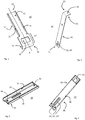
- Figure 1 shows a support element 10 according to the invention in an oblique view of the upper side 11.
- the longitudinal axis A is marked with a dashed line.
- the flat contact surface 17 can be seen at the front end 13, which merges into a beveled angle element which forms a stop surface 18 which merges into the underside 12 of the support element.
- the second longitudinal section extends in the direction of the rear end 14.
- the two guide elements 15 and 15, which are designed as bent edges or webs aligned parallel to the axis A, are also found on the second longitudinal section.
- Feature 19 shows a recess in the area of the contact surface 17, which serves to save weight.
- Figure 2 shows the supplementary bracket 20 with its first (short) leg 21, which contains the connecting end 23, and the second leg 22, which forms the fastening end 24.
- a fastening point 25 is indicated at the connecting end 23; at the fastening end 24 two bores 26, 26 'are shown by way of example.
- a specialist will select their location and dimensions for each requirement profile.
- Figure 3 shows a profile rail 30 as it is already known in the prior art as a holding element.
- a profile rail 30 designed essentially as a U-body, the webs 35 and 36 ensuring the longitudinal rigidity.
- the bottom 38 of the profile rail 30 is dimensioned such that it can be attached to the top of the support element 10 in a form-fitting manner.
- Feature 34 is an opening through which a fastener can be passed to support member 10 (not shown in FIG Figure 3 ).
- Figure 4 shows a reinforced variant 30 'of a profile rail.
- the design is designed as a hollow box, which is closed in cross-section over long distances, with lateral webs 35, 36.
- bores 34, 34 ', ... are attached to one longitudinal end through which fasteners can be guided.
- the recess at the other longitudinal end of the profile rail 30 ′ shows the receptacle 32, which can serve as an interface to the table element 31.
- the recess makes it possible to use the same table element 31 structurally identical for a profile rail of type 30 such as type 30 '.
- Figure 5 shows a combination of profile rail 30 with a plate-like, flat table element 31.
- the connection takes place via the receptacle 32, which is concealed here and into which a pin or pin on the underside of the table element 31 engages.
- Figure 6 shows in training of Figure 5 , the combination of profile rail 10 / table element 31 with a support element 10.
- the webs 35 and 36, in interaction with the guide elements 15, 16, result in a form fit in the transverse direction.
- the profile rail 30 remains longitudinally displaceable until it is fixed by a fastener 45.
- the profile rail 30 rests on the contact surface 17, among other things.
- the attachment of the contact element 10 via bracket 20 is shown in FIG Figures 8 and 9 shown in Figure 6 on the other hand omitted.
- Figure 7 shows a support bracket 50.
- a first leg 52 is designed to be similar to a profile rail Figure 3 or. Figure 4 to be hung up. For this purpose, it can have guide lugs, edges or webs 51, 53 which support alignment on the profile rail.
- a second leg 54 is arranged essentially at right angles to the first leg 52. Both legs carry bores, openings, elongated holes or connection points 56, 58, 58 ', ... around the support bracket properly on a profile rail 30 or 30'.
- the arrangement of a single fastening opening / bore 58 on the first leg 52, laterally on the guide edges or webs 51, 53, has the advantage that a fastener inserted there is only anchored in the profile rail and there is sheared instead of tensile .
- FIGS. 8 and 9 show two mounting situations of a device according to the invention on a wall opening.
- a section of a wall 40 is shown with a parapet or parapet surface 42.
- a support element 10 rests on the parapet surface 42 so that the stop surface 18 engages around an edge 41 of the wall opening and rests on one side (outside) of the wall opening.
- the bracket 20 is connected to the support element 10 on the parapet side (attachment point 46 on the short leg 21) and on the other hand, on the inside 44 of the wall opening through the second leg 22, anchored or screwed on (via opening 20).
- Figure 9 further shows how a profile rail 30 can be arranged on the support element 10 and is fixed by a fastener 45.
- the variant of the profile rail 30 shown has the plate-like, flat table element 31 at its longitudinal end.
- An attached angle element 50 is also shown.
Landscapes
- Engineering & Computer Science (AREA)
- Mechanical Engineering (AREA)
- Civil Engineering (AREA)
- Structural Engineering (AREA)
- Support Devices For Sliding Doors (AREA)
Priority Applications (2)
| Application Number | Priority Date | Filing Date | Title |
|---|---|---|---|
| EP20157432.4A EP3865654B1 (fr) | 2020-02-14 | 2020-02-14 | Dispositif de support d'éléments de fenêtre ou de porte et procédé de montage d'un tel dispositif |
| PL20157432.4T PL3865654T3 (pl) | 2020-02-14 | 2020-02-14 | Układ do podpierania elementów okiennych albo drzwiowych i sposób montażu takiego układu |
Applications Claiming Priority (1)
| Application Number | Priority Date | Filing Date | Title |
|---|---|---|---|
| EP20157432.4A EP3865654B1 (fr) | 2020-02-14 | 2020-02-14 | Dispositif de support d'éléments de fenêtre ou de porte et procédé de montage d'un tel dispositif |
Publications (2)
| Publication Number | Publication Date |
|---|---|
| EP3865654A1 true EP3865654A1 (fr) | 2021-08-18 |
| EP3865654B1 EP3865654B1 (fr) | 2025-04-09 |
Family
ID=69630158
Family Applications (1)
| Application Number | Title | Priority Date | Filing Date |
|---|---|---|---|
| EP20157432.4A Active EP3865654B1 (fr) | 2020-02-14 | 2020-02-14 | Dispositif de support d'éléments de fenêtre ou de porte et procédé de montage d'un tel dispositif |
Country Status (2)
| Country | Link |
|---|---|
| EP (1) | EP3865654B1 (fr) |
| PL (1) | PL3865654T3 (fr) |
Citations (4)
| Publication number | Priority date | Publication date | Assignee | Title |
|---|---|---|---|---|
| EP0945577A2 (fr) | 1998-03-23 | 1999-09-29 | SFS Industrie Holding AG | Dispositif de support d'encadrements pour portes ou fenêtres à la périphérie d'une ouverture de paroi |
| EP1500767A2 (fr) | 2003-07-25 | 2005-01-26 | SFS intec Holding AG | Dispositif de support et de fixation d'encadrements pour portes ou fenêtres à la périphérie d'une ouverture de paroi |
| EP2733293A1 (fr) * | 2012-11-15 | 2014-05-21 | Wolfgang Haas | Système de cadre de montage |
| DE102018117362A1 (de) * | 2018-07-18 | 2020-01-23 | Simone Niemann | Befestigungsvorrichtung für einen Fenster- oder Türrahmen an einem Mauerwerk |
-
2020
- 2020-02-14 PL PL20157432.4T patent/PL3865654T3/pl unknown
- 2020-02-14 EP EP20157432.4A patent/EP3865654B1/fr active Active
Patent Citations (4)
| Publication number | Priority date | Publication date | Assignee | Title |
|---|---|---|---|---|
| EP0945577A2 (fr) | 1998-03-23 | 1999-09-29 | SFS Industrie Holding AG | Dispositif de support d'encadrements pour portes ou fenêtres à la périphérie d'une ouverture de paroi |
| EP1500767A2 (fr) | 2003-07-25 | 2005-01-26 | SFS intec Holding AG | Dispositif de support et de fixation d'encadrements pour portes ou fenêtres à la périphérie d'une ouverture de paroi |
| EP2733293A1 (fr) * | 2012-11-15 | 2014-05-21 | Wolfgang Haas | Système de cadre de montage |
| DE102018117362A1 (de) * | 2018-07-18 | 2020-01-23 | Simone Niemann | Befestigungsvorrichtung für einen Fenster- oder Türrahmen an einem Mauerwerk |
Also Published As
| Publication number | Publication date |
|---|---|
| PL3865654T3 (pl) | 2025-06-30 |
| EP3865654B1 (fr) | 2025-04-09 |
Similar Documents
| Publication | Publication Date | Title |
|---|---|---|
| EP3594427B1 (fr) | Système et procédé de fixation d'éléments de façade | |
| EP0180837B1 (fr) | Jeu de pièces séparées pour un dispositif de fixation de murs rideaux | |
| DE102007036670B4 (de) | Bausatz zum Aufbau eines Fußbodens für ein Schienenfahrzeug | |
| EP3736391B1 (fr) | Support d'élément de façade | |
| EP3365510B1 (fr) | Système destiné à l'habillage de murs, plafonds ou toits d'un corps de bâtiment | |
| EP3546673A1 (fr) | Système de fixation de façade | |
| EP3636844B1 (fr) | Cadre de construction en mur sec pour une porte coulissante | |
| AT527298B1 (de) | Agraffenprofil und System umfassend Agraffenprofil und Agraffe | |
| DE102007037271A1 (de) | Vorrichtung zum Befestigen von plattenartigen Verkleidungselementen | |
| DE20003056U1 (de) | Befestigungsvorrichtung für plattenförmige Fassadenelemente | |
| DE102021103756A1 (de) | Adapter zur Halterung von Fassadenelementen | |
| EP3865654B1 (fr) | Dispositif de support d'éléments de fenêtre ou de porte et procédé de montage d'un tel dispositif | |
| EP3628806B1 (fr) | Dispositif de fixation d'un corps de construction dans une ouverture de mur | |
| DE102012211638A1 (de) | Verankerungssystem | |
| DE102019114492A1 (de) | Befestigungssystem mit Kraftverteilung | |
| DE102016213293A1 (de) | Beschlag, Beschlagsatz und Verfahren zum Befestigen von Fenster- und Türrahmen | |
| DE10134396C1 (de) | Bausatz zum Einsetzen eines Wandelementes in eine Wandöffnung einer doppelschaligen Ständerwand | |
| EP0026495A2 (fr) | Jeu de profilés pour la fixation d'une infrastructure de panneaux de revêtement à une façade | |
| EP2775083B1 (fr) | Assemblage de fixation, utilisation d'un dispositif et procédé de fixation d'un corps de bâtiment dans une ouverture limitée par une surface d'appui | |
| EP4074917B1 (fr) | Montage d'une structure de protection contre les chutes à un cadre au moyen d'un corps de fixation sans connexion directe à un dispositif de fixation de cadre | |
| DE102021107547B4 (de) | Montageset zur Montage eines Rahmens an einer Öffnung eines Verankerungsgrunds mittels biegestabiler Verbindung zwischen Konsolenprofil und Anbauteil, sowie Anordnung und Verfahren hierfür | |
| EP2604868B1 (fr) | Dispositif et procédé destinés à la liaison de composants | |
| EP1717452A1 (fr) | Dispositif de liaison de deux éléments de construction | |
| DE102006020259A1 (de) | Verbindungsvorrichtung zum Verbinden von zwei Bauteilen | |
| EP3696361B1 (fr) | Dispositif de support d'éléments de fenêtre ou de porte |
Legal Events
| Date | Code | Title | Description |
|---|---|---|---|
| PUAI | Public reference made under article 153(3) epc to a published international application that has entered the european phase |
Free format text: ORIGINAL CODE: 0009012 |
|
| STAA | Information on the status of an ep patent application or granted ep patent |
Free format text: STATUS: THE APPLICATION HAS BEEN PUBLISHED |
|
| AK | Designated contracting states |
Kind code of ref document: A1 Designated state(s): AL AT BE BG CH CY CZ DE DK EE ES FI FR GB GR HR HU IE IS IT LI LT LU LV MC MK MT NL NO PL PT RO RS SE SI SK SM TR |
|
| STAA | Information on the status of an ep patent application or granted ep patent |
Free format text: STATUS: REQUEST FOR EXAMINATION WAS MADE |
|
| 17P | Request for examination filed |
Effective date: 20220218 |
|
| RBV | Designated contracting states (corrected) |
Designated state(s): AL AT BE BG CH CY CZ DE DK EE ES FI FR GB GR HR HU IE IS IT LI LT LU LV MC MK MT NL NO PL PT RO RS SE SI SK SM TR |
|
| RAP3 | Party data changed (applicant data changed or rights of an application transferred) |
Owner name: SFS GROUP INTERNATIONAL AG |
|
| GRAP | Despatch of communication of intention to grant a patent |
Free format text: ORIGINAL CODE: EPIDOSNIGR1 |
|
| STAA | Information on the status of an ep patent application or granted ep patent |
Free format text: STATUS: GRANT OF PATENT IS INTENDED |
|
| GRAS | Grant fee paid |
Free format text: ORIGINAL CODE: EPIDOSNIGR3 |
|
| INTG | Intention to grant announced |
Effective date: 20241212 |
|
| GRAA | (expected) grant |
Free format text: ORIGINAL CODE: 0009210 |
|
| STAA | Information on the status of an ep patent application or granted ep patent |
Free format text: STATUS: THE PATENT HAS BEEN GRANTED |
|
| AK | Designated contracting states |
Kind code of ref document: B1 Designated state(s): AL AT BE BG CH CY CZ DE DK EE ES FI FR GB GR HR HU IE IS IT LI LT LU LV MC MK MT NL NO PL PT RO RS SE SI SK SM TR |
|
| REG | Reference to a national code |
Ref country code: GB Ref legal event code: FG4D Free format text: NOT ENGLISH |
|
| REG | Reference to a national code |
Ref country code: CH Ref legal event code: EP |
|
| REG | Reference to a national code |
Ref country code: DE Ref legal event code: R096 Ref document number: 502020010775 Country of ref document: DE |
|
| REG | Reference to a national code |
Ref country code: IE Ref legal event code: FG4D Free format text: LANGUAGE OF EP DOCUMENT: GERMAN |
|
| REG | Reference to a national code |
Ref country code: SE Ref legal event code: TRGR |
|
| REG | Reference to a national code |
Ref country code: NL Ref legal event code: MP Effective date: 20250409 |
|
| PG25 | Lapsed in a contracting state [announced via postgrant information from national office to epo] |
Ref country code: NL Free format text: LAPSE BECAUSE OF FAILURE TO SUBMIT A TRANSLATION OF THE DESCRIPTION OR TO PAY THE FEE WITHIN THE PRESCRIBED TIME-LIMIT Effective date: 20250409 |
|
| PG25 | Lapsed in a contracting state [announced via postgrant information from national office to epo] |
Ref country code: FI Free format text: LAPSE BECAUSE OF FAILURE TO SUBMIT A TRANSLATION OF THE DESCRIPTION OR TO PAY THE FEE WITHIN THE PRESCRIBED TIME-LIMIT Effective date: 20250409 Ref country code: ES Free format text: LAPSE BECAUSE OF FAILURE TO SUBMIT A TRANSLATION OF THE DESCRIPTION OR TO PAY THE FEE WITHIN THE PRESCRIBED TIME-LIMIT Effective date: 20250409 Ref country code: PT Free format text: LAPSE BECAUSE OF FAILURE TO SUBMIT A TRANSLATION OF THE DESCRIPTION OR TO PAY THE FEE WITHIN THE PRESCRIBED TIME-LIMIT Effective date: 20250811 |
|
| REG | Reference to a national code |
Ref country code: LT Ref legal event code: MG9D |
|
| PG25 | Lapsed in a contracting state [announced via postgrant information from national office to epo] |
Ref country code: GR Free format text: LAPSE BECAUSE OF FAILURE TO SUBMIT A TRANSLATION OF THE DESCRIPTION OR TO PAY THE FEE WITHIN THE PRESCRIBED TIME-LIMIT Effective date: 20250710 Ref country code: NO Free format text: LAPSE BECAUSE OF FAILURE TO SUBMIT A TRANSLATION OF THE DESCRIPTION OR TO PAY THE FEE WITHIN THE PRESCRIBED TIME-LIMIT Effective date: 20250709 |
|
| PG25 | Lapsed in a contracting state [announced via postgrant information from national office to epo] |
Ref country code: BG Free format text: LAPSE BECAUSE OF FAILURE TO SUBMIT A TRANSLATION OF THE DESCRIPTION OR TO PAY THE FEE WITHIN THE PRESCRIBED TIME-LIMIT Effective date: 20250409 |
|
| PG25 | Lapsed in a contracting state [announced via postgrant information from national office to epo] |
Ref country code: HR Free format text: LAPSE BECAUSE OF FAILURE TO SUBMIT A TRANSLATION OF THE DESCRIPTION OR TO PAY THE FEE WITHIN THE PRESCRIBED TIME-LIMIT Effective date: 20250409 |
|
| PG25 | Lapsed in a contracting state [announced via postgrant information from national office to epo] |
Ref country code: RS Free format text: LAPSE BECAUSE OF FAILURE TO SUBMIT A TRANSLATION OF THE DESCRIPTION OR TO PAY THE FEE WITHIN THE PRESCRIBED TIME-LIMIT Effective date: 20250709 |
|
| PG25 | Lapsed in a contracting state [announced via postgrant information from national office to epo] |
Ref country code: IS Free format text: LAPSE BECAUSE OF FAILURE TO SUBMIT A TRANSLATION OF THE DESCRIPTION OR TO PAY THE FEE WITHIN THE PRESCRIBED TIME-LIMIT Effective date: 20250809 |
|
| PG25 | Lapsed in a contracting state [announced via postgrant information from national office to epo] |
Ref country code: LV Free format text: LAPSE BECAUSE OF FAILURE TO SUBMIT A TRANSLATION OF THE DESCRIPTION OR TO PAY THE FEE WITHIN THE PRESCRIBED TIME-LIMIT Effective date: 20250409 |
|
| REG | Reference to a national code |
Ref country code: DE Ref legal event code: R097 Ref document number: 502020010775 Country of ref document: DE |
|
| PG25 | Lapsed in a contracting state [announced via postgrant information from national office to epo] |
Ref country code: SM Free format text: LAPSE BECAUSE OF FAILURE TO SUBMIT A TRANSLATION OF THE DESCRIPTION OR TO PAY THE FEE WITHIN THE PRESCRIBED TIME-LIMIT Effective date: 20250409 Ref country code: DK Free format text: LAPSE BECAUSE OF FAILURE TO SUBMIT A TRANSLATION OF THE DESCRIPTION OR TO PAY THE FEE WITHIN THE PRESCRIBED TIME-LIMIT Effective date: 20250409 |
|
| PG25 | Lapsed in a contracting state [announced via postgrant information from national office to epo] |
Ref country code: CZ Free format text: LAPSE BECAUSE OF FAILURE TO SUBMIT A TRANSLATION OF THE DESCRIPTION OR TO PAY THE FEE WITHIN THE PRESCRIBED TIME-LIMIT Effective date: 20250409 |
|
| PG25 | Lapsed in a contracting state [announced via postgrant information from national office to epo] |
Ref country code: EE Free format text: LAPSE BECAUSE OF FAILURE TO SUBMIT A TRANSLATION OF THE DESCRIPTION OR TO PAY THE FEE WITHIN THE PRESCRIBED TIME-LIMIT Effective date: 20250409 |
|
| PG25 | Lapsed in a contracting state [announced via postgrant information from national office to epo] |
Ref country code: RO Free format text: LAPSE BECAUSE OF FAILURE TO SUBMIT A TRANSLATION OF THE DESCRIPTION OR TO PAY THE FEE WITHIN THE PRESCRIBED TIME-LIMIT Effective date: 20250409 Ref country code: SK Free format text: LAPSE BECAUSE OF FAILURE TO SUBMIT A TRANSLATION OF THE DESCRIPTION OR TO PAY THE FEE WITHIN THE PRESCRIBED TIME-LIMIT Effective date: 20250409 |
|
| PG25 | Lapsed in a contracting state [announced via postgrant information from national office to epo] |
Ref country code: IT Free format text: LAPSE BECAUSE OF FAILURE TO SUBMIT A TRANSLATION OF THE DESCRIPTION OR TO PAY THE FEE WITHIN THE PRESCRIBED TIME-LIMIT Effective date: 20250409 |
|
| PLBE | No opposition filed within time limit |
Free format text: ORIGINAL CODE: 0009261 |
|
| STAA | Information on the status of an ep patent application or granted ep patent |
Free format text: STATUS: NO OPPOSITION FILED WITHIN TIME LIMIT |
|
| REG | Reference to a national code |
Ref country code: CH Ref legal event code: L10 Free format text: ST27 STATUS EVENT CODE: U-0-0-L10-L00 (AS PROVIDED BY THE NATIONAL OFFICE) Effective date: 20260218 |
|
| 26N | No opposition filed |
Effective date: 20260112 |
|
| PGFP | Annual fee paid to national office [announced via postgrant information from national office to epo] |
Ref country code: SE Payment date: 20260218 Year of fee payment: 7 |
|
| PGFP | Annual fee paid to national office [announced via postgrant information from national office to epo] |
Ref country code: GB Payment date: 20260219 Year of fee payment: 7 |
|
| PGFP | Annual fee paid to national office [announced via postgrant information from national office to epo] |
Ref country code: DE Payment date: 20260217 Year of fee payment: 7 |
|
| PGFP | Annual fee paid to national office [announced via postgrant information from national office to epo] |
Ref country code: FR Payment date: 20260219 Year of fee payment: 7 |