EP3865705A1 - Éolienne, ainsi que procédé de surveillance d'un entrainement azimutal de l'éolienne - Google Patents
Éolienne, ainsi que procédé de surveillance d'un entrainement azimutal de l'éolienne Download PDFInfo
- Publication number
- EP3865705A1 EP3865705A1 EP21155802.8A EP21155802A EP3865705A1 EP 3865705 A1 EP3865705 A1 EP 3865705A1 EP 21155802 A EP21155802 A EP 21155802A EP 3865705 A1 EP3865705 A1 EP 3865705A1
- Authority
- EP
- European Patent Office
- Prior art keywords
- pinion
- sensor unit
- alignment
- sensor
- wind energy
- Prior art date
- Legal status (The legal status is an assumption and is not a legal conclusion. Google has not performed a legal analysis and makes no representation as to the accuracy of the status listed.)
- Granted
Links
Images




Classifications
-
- F—MECHANICAL ENGINEERING; LIGHTING; HEATING; WEAPONS; BLASTING
- F03—MACHINES OR ENGINES FOR LIQUIDS; WIND, SPRING, OR WEIGHT MOTORS; PRODUCING MECHANICAL POWER OR A REACTIVE PROPULSIVE THRUST, NOT OTHERWISE PROVIDED FOR
- F03D—WIND MOTORS
- F03D7/00—Controlling wind motors
- F03D7/02—Controlling wind motors the wind motors having rotation axis substantially parallel to the air flow entering the rotor
- F03D7/0204—Controlling wind motors the wind motors having rotation axis substantially parallel to the air flow entering the rotor for orientation in relation to wind direction
-
- F—MECHANICAL ENGINEERING; LIGHTING; HEATING; WEAPONS; BLASTING
- F03—MACHINES OR ENGINES FOR LIQUIDS; WIND, SPRING, OR WEIGHT MOTORS; PRODUCING MECHANICAL POWER OR A REACTIVE PROPULSIVE THRUST, NOT OTHERWISE PROVIDED FOR
- F03D—WIND MOTORS
- F03D17/00—Monitoring or testing of wind motors, e.g. diagnostics
-
- F—MECHANICAL ENGINEERING; LIGHTING; HEATING; WEAPONS; BLASTING
- F03—MACHINES OR ENGINES FOR LIQUIDS; WIND, SPRING, OR WEIGHT MOTORS; PRODUCING MECHANICAL POWER OR A REACTIVE PROPULSIVE THRUST, NOT OTHERWISE PROVIDED FOR
- F03D—WIND MOTORS
- F03D80/00—Details, components or accessories not provided for in groups F03D1/00 - F03D17/00
- F03D80/70—Bearing or lubricating arrangements
-
- F—MECHANICAL ENGINEERING; LIGHTING; HEATING; WEAPONS; BLASTING
- F03—MACHINES OR ENGINES FOR LIQUIDS; WIND, SPRING, OR WEIGHT MOTORS; PRODUCING MECHANICAL POWER OR A REACTIVE PROPULSIVE THRUST, NOT OTHERWISE PROVIDED FOR
- F03D—WIND MOTORS
- F03D80/00—Details, components or accessories not provided for in groups F03D1/00 - F03D17/00
-
- F—MECHANICAL ENGINEERING; LIGHTING; HEATING; WEAPONS; BLASTING
- F05—INDEXING SCHEMES RELATING TO ENGINES OR PUMPS IN VARIOUS SUBCLASSES OF CLASSES F01-F04
- F05B—INDEXING SCHEME RELATING TO WIND, SPRING, WEIGHT, INERTIA OR LIKE MOTORS, TO MACHINES OR ENGINES FOR LIQUIDS COVERED BY SUBCLASSES F03B, F03D AND F03G
- F05B2260/00—Function
- F05B2260/70—Adjusting of angle of incidence or attack of rotating blades
- F05B2260/79—Bearing, support or actuation arrangements therefor
-
- F—MECHANICAL ENGINEERING; LIGHTING; HEATING; WEAPONS; BLASTING
- F05—INDEXING SCHEMES RELATING TO ENGINES OR PUMPS IN VARIOUS SUBCLASSES OF CLASSES F01-F04
- F05B—INDEXING SCHEME RELATING TO WIND, SPRING, WEIGHT, INERTIA OR LIKE MOTORS, TO MACHINES OR ENGINES FOR LIQUIDS COVERED BY SUBCLASSES F03B, F03D AND F03G
- F05B2270/00—Control
- F05B2270/10—Purpose of the control system
- F05B2270/109—Purpose of the control system to prolong engine life
- F05B2270/1095—Purpose of the control system to prolong engine life by limiting mechanical stresses
-
- Y—GENERAL TAGGING OF NEW TECHNOLOGICAL DEVELOPMENTS; GENERAL TAGGING OF CROSS-SECTIONAL TECHNOLOGIES SPANNING OVER SEVERAL SECTIONS OF THE IPC; TECHNICAL SUBJECTS COVERED BY FORMER USPC CROSS-REFERENCE ART COLLECTIONS [XRACs] AND DIGESTS
- Y02—TECHNOLOGIES OR APPLICATIONS FOR MITIGATION OR ADAPTATION AGAINST CLIMATE CHANGE
- Y02E—REDUCTION OF GREENHOUSE GAS [GHG] EMISSIONS, RELATED TO ENERGY GENERATION, TRANSMISSION OR DISTRIBUTION
- Y02E10/00—Energy generation through renewable energy sources
- Y02E10/70—Wind energy
- Y02E10/72—Wind turbines with rotation axis in wind direction
Definitions
- the invention relates to a wind power plant with an azimuth bearing that has azimuth gearing and at least one azimuth drive that is coupled to an azimuth gear corresponding to the azimuth gearing, the azimuth gear having a drive pinion that is rotatable about a pinion axis, the drive pinion being configured for this purpose to engage in the corresponding azimuth toothing of the azimuth bearing, the pinion axis having a predetermined reference orientation.
- the invention also relates to a method for monitoring an azimuth drive of a wind energy installation, preferably a wind energy installation of the type mentioned at the beginning.
- Wind turbines are well known. They have a tower on which a gondola is rotatably mounted. This bearing is usually referred to as an azimuth bearing. Depending on the type of turbine, the wind turbine has a large number of azimuth drives. These are set up to track the wind of the nacelle so that the rotor can be correctly aligned even when the wind direction changes.
- An azimuth drive has a drive motor which usually drives a drive shaft via an azimuth gear.
- a drive pinion is arranged on the drive shaft and is cantilevered on a lower pinion shaft bearing.
- the drive is usually rotating quickly with low torque and the drive shaft rotating slowly with high torque.
- the high torque is then transmitted from the drive shaft via the drive pinion, i.e. a small gear, to a large gear, for example an internal toothing of the azimuth bearing, in the area of a transition between the tower and the nacelle, in order to adjust the nacelle horizontally by an azimuth angle.
- a correspondingly high drive torque is transmitted to adjust the gondola.
- the drive pinion Due to its storage and the high loads, the drive pinion tends to move laterally from its normal alignment, hereinafter also reference alignment, from the azimuth toothing during operation. H. to bend away. Under certain unfavorable circumstances, this can lead to wear of the pinion shaft bearing over time, as a result of which the drive pinion can be deflected from its ideal position, that is to say if the bearing is intact.
- a defective pinion shaft bearing means that the pinion shaft of the azimuth gear can no longer be guided without play. When a certain deflection is reached, engagement of the toothing of the drive pinion into the corresponding toothing of the azimuth bearing is accordingly no longer possible.
- the invention was thus based on the object of improving a wind energy installation of the type described at the outset in such a way that the disadvantages found in the prior art are overcome as far as possible.
- lay The object of the invention is to improve a wind turbine in such a way that damage and / or wear and tear of the pinion shaft bearing is detected as early as possible and thus the risk of serious damage to the azimuth gearing and failure of the azimuth drive can be reduced or prevented, but at least downtimes and repair costs to minimize.
- the object is achieved in a first aspect by a wind energy installation of the type mentioned at the beginning, the wind energy installation having at least one sensor unit which is set up to detect a deviation in the orientation of the pinion axis relative to the reference orientation.
- detection is understood to mean that a sensor monitors the alignment of the pinion axis directly or indirectly. This means that a sensor which, for example, monitors the movement of an end face of the drive pinion that is caused by a deflection of the pinion axis, thus also detects a deflection of the pinion axis according to the invention.
- a reference alignment is understood to mean an alignment of the pinion axis of the drive pinion in the assembled state and when the wind energy installation is at a standstill.
- the sensor unit preferably has an inductive sensor and / or a mechanical sensor. According to the invention it is provided to use one sensor unit per drive pinion to monitor the alignment of the pinion axis. In some cases it can make sense to use several sensor units per drive pinion. This can be done using the same sensor types or different sensor types. The same sensor types have the advantage of simple maintenance and control. With the help of different sensor types, the risk of a simultaneous failure of both sensor types is reduced. In addition, the comparability and the informative value of the detected values are increased, since incorrect measurements can be identified more easily.
- inductive sensors With the help of inductive sensors, electrically conductive materials, e.g. metallic materials, can be detected. Due to their insensitivity to environmental influences, it is possible to achieve a high level of measurement accuracy even in a dusty atmosphere or in the event of vibrations and shocks.
- the mechanical sensor can be a touch sensor or a stop sensor.
- a touch sensor is understood to be a sensor that senses the position of a workpiece.
- a stop sensor or limit switch emits a signal when the workpiece to be measured has reached the corresponding stop or the end position.
- the sensor unit is set up to detect a deviation in the alignment of the pinion axis relative to the reference alignment without contact.
- contact-free detection in particular of a distance to a measurement object or a position of a measurement object, no mechanical wear of the sensor occurs. Accordingly, a shorter maintenance interval is required.
- non-contact sensors are also less susceptible to vibration.
- the sensor unit is preferably set up to detect a deviation in the alignment of the pinion axis relative to the reference alignment with contact.
- Touch sensors also known as tactile sensors, react to mechanical contact and can pass them on in binary, analog or digital signals.
- the sensor unit has a digital sensor, in particular a binary sensor.
- binary sensors are to be understood as sensors which convert a discrete physical measured value into a binary signal.
- Binary sensors differentiate between two states, i.e. whether z. B. the position to be determined is taken by the detected object or not.
- the binary signal transmission enables a fast and compact signal processing, since the digital basic links only the binary state of the Query input. Furthermore, only a slight loss of accuracy is to be expected, since there are only two possible states.
- the sensor unit has an analog sensor.
- analog sensors are to be understood as sensors which convert a physical measured value into an analog signal, that is to say, for example, an electrical analog signal such as a voltage or a current.
- the advantage of analog data acquisition would be a higher and therefore more precise resolution range. In this way, a higher information density can be recorded and thus, for example, a preliminary evaluation can be carried out in the sensor itself.
- the sensitivity to external influences is greater.
- the sensor unit is set up to detect the deviation of the alignment of the pinion axis relative to the reference alignment on the basis of a change in position of a reference geometry assigned to the drive pinion.
- a reference geometry is preferably selected from at least a partial section of the drive pinion, preferably selected from one of the following: the toothing of the drive pinion, in particular also sections of the toothing of the drive pinion, i.e. one tooth or more teeth, one or more tooth flanks, a tip circle (diameter), in particular the head surface of a tooth, or a root circle (diameter), at least a section of the end face of the drive pinion, preferably a section within the root circle of the drive pinion or a section within the area that is delimited by the root circle and the tip circle of the drive pinion, or the Outer surface of the pinion shaft.
- a change in position of the toothing relative to the reference alignment can be determined.
- a change in the angle of the pinion axis relative to the reference alignment can in particular be determined.
- a reference point can be selected and determined from the selected reference geometry, in particular the center point of the tip circle and / or the root circle based on a respective radius of the tip circle / root circle of the drive pinion.
- the sensor unit preferably has a distance sensor for measuring a distance between the reference geometry and the sensor unit.
- a distance sensor for measuring a distance between the reference geometry and the sensor unit.
- continuous readings can be recorded.
- fluctuations in the distance can be evaluated in an improved manner, so that, for example, noise in the measurement results, triggered by vibrations during operation, can be filtered out. This enables, among other things, the investigation and evaluation of the change in the distance over a longer period of time, in particular also the investigation and evaluation of the distance with different load cases and different environmental conditions.
- the sensor unit has a proximity sensor for detecting a position, in particular a limit position, of the reference geometry.
- This sensor variant represents a simpler measuring device. Two states are determined, the sensor unit transmitting an interference signal in the second state, that is to say when the reference geometry has reached or exceeded a defined limit position.
- the wind energy installation preferably has a machine support and the sensor unit is arranged on the machine support of the wind energy installation.
- the drive pinion has a pinion shaft which is mounted on a lower pinion shaft bearing and the sensor unit is positioned between the pinion shaft bearing and the drive pinion, preferably between the pinion shaft bearing and an end face, in particular a part of the end face within the root circle, the drive pinion and is aligned with the drive pinion or a peripheral surface of the pinion shaft.
- the sensor unit is arranged between the pinion shaft bearing and the drive pinion and is aligned with a lateral surface of the pinion shaft.
- An inductive sensor can be used to detect a movement or deflection of the end face of the drive pinion.
- the inductive sensor can be aligned both to a full surface, ie an area within the root circle of the drive pinion, and to, for example, the toothing of the drive pinion.
- Another possible embodiment relates to the use of a mechanical sensor.
- the switching logic is preferably used in such a way that that the sensor unit transmits an interfering signal upon contact, in particular the end face or the lateral surface of the drive pinion.
- the at least one sensor unit is positioned at a horizontal distance from the tip diameter of the drive pinion.
- An inductive sensor or a mechanical sensor is preferably used at this position.
- the sensor units are each set up to monitor a deflection of the toothing.
- the field to be monitored should preferably be selected so that several teeth or several tooth flanks serve as reference geometry.
- Two inductive sensor units are particularly preferably used for monitoring the alignment of the pinion axis, a first sensor and a second sensor being positioned in such a way that, during operation, i. H. when the pinion rotates about a pinion axis, at least one tooth is constantly in the measuring range of at least one sensor.
- the sensor unit is preferably arranged below the drive pinion and aligned with the drive pinion, in particular a part of an end face within the root circle of the drive pinion.
- An inductive sensor can be used to detect a movement or deflection of the end face of the drive pinion.
- the inductive sensor can be applied to a full surface, i.e. H. an area within the root circle of the drive pinion as well as, for example, the toothing of the drive pinion.
- Another possible embodiment relates to the use of a mechanical sensor.
- the switching logic is preferably to be used in such a way that the sensor unit transmits an interference signal in the event of a loss of contact, in particular to the end face of the drive pinion.
- the wind energy installation has a controller which is set up to detect a deviation in the alignment of the pinion axis relative to the reference alignment, which is representative of the presence of a disturbance.
- the object is achieved by a method for monitoring an azimuth drive of a wind energy installation, preferably a wind energy installation Initially mentioned type, wherein the azimuth drive has a drive pinion which is rotatable about a pinion axis, the pinion axis having a predetermined reference orientation, the method comprising the step of: detecting, in particular contact-free or with contact, a deviation in the orientation of the pinion axis relative to the reference orientation with a sensor unit.
- the method preferably has the following steps: detecting the reference orientation of the pinion axis with the sensor unit, and / or predefining the reference orientation of the pinion axis and feeding the predefined reference orientation into the sensor unit. It is possible, depending on the type of sensor used, to define a zero position in advance and to feed this into the sensor unit, i. H. for example with the help of a calibration function. As an alternative or in addition, the invention provides for a reference alignment to be detected with the aid of the sensor unit, for example the position or location of the pinion axis, and for this to be assigned as a reference position.
- the sensor unit has a data interface and is set up to be programmed by means of the data interface, wherein preferably a data set can be stored by means of the data interface, which is representative of a previously recorded reference alignment of the pinion axis.
- the method preferably also has the step of: detecting the deviation of the alignment of the pinion axis relative to the reference alignment on the basis of a change in position of a reference geometry assigned to the drive pinion.
- the method preferably also has the step (s): converting a physical measured value into a binary signal by means of the sensor unit, and / or converting a physical measured value into an analog signal by means of the sensor unit.
- the method furthermore preferably has the step (s): measuring a distance between the reference geometry and the sensor unit by means of the sensor unit, and / or detecting a position of the reference geometry by means of the sensor unit.
- the method preferably also has the step of generating an interference signal when a deviation in the alignment of the pinion axis of the drive pinion, which is representative of the presence of a fault, is detected.
- the deviation in the alignment of the pinion axis of the drive pinion is determined by comparing the current deviation in the alignment of the pinion axis of the drive pinion relative to a limit value which is representative of the presence of a fault. This is preferably done with the help of the control of the wind energy installation.
- the sensor unit acts as a signal transmitter. In an alternative embodiment, an evaluation can also be carried out directly by a control unit within the sensor unit itself.
- the method preferably also has the step (s): approaching a parking position of the wind energy installation and / or switching off the wind energy installation.
- a wind energy installation comprises, in particular, several azimuth drives. In order to rule out any operational disruptions, the immediate possibility of troubleshooting is created herewith.
- the method further comprises the step of switching off the azimuth drive coupled to the drive pinion with the aid of the controller if a deviation in the alignment of the pinion axis of the drive pinion, which is representative of the presence of a fault, is detected.
- a deviation in the alignment of the pinion axis of the drive pinion which is representative of the presence of a fault, is detected.
- it can make sense to switch the drive pinion to an idle position. This ensures that a parking position can be approached more securely until potential damage to the wind energy installation, in particular to the toothing of the drive pinion and / or the toothing of the azimuth bearing and / or the pinion shaft bearing, has been checked and repaired.
- Figure 1 shows a wind energy installation 100 with a tower 102 and a nacelle 104.
- a rotor 106 with three rotor blades 108 and a spinner 110 is arranged on the nacelle 104.
- the rotor 106 is set in rotation by the wind during operation and thereby drives a generator 118 ( Fig. 2 ) in gondola 104.
- the nacelle 104 of the wind energy installation 100 according to FIG Fig. 1 is in Fig. 2 shown schematically in a partially sectioned view.
- the nacelle 104 is rotatably mounted on the tower 102 by means of an azimuth bearing 120 and can be driven by means of an azimuth drive 112.
- a machine carrier 116 which carries an axle journal 114, is arranged in the gondola 104.
- Fig. 3 shows an example of an azimuth drive 112 which is fastened to a support structure 134 in such a way that a drive pinion 140, which is formed on the respective azimuth drive 112 on the tower side, is operatively connected to the azimuth toothing 124.
- the drive pinion 140 is driven by means of a drive of the azimuth drive 112 and is set up to engage in a corresponding azimuth toothing 124 by means of a rotary movement about a pinion axis R.
- Fig. 3 it can be seen that the drive pinion 140 engages in an internally toothed azimuth toothing 124 in this exemplary embodiment.
- the azimuth drive 112 and the drive pinion 140 are aligned along a pinion axis R. This has a reference alignment during normal operation.
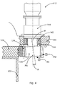
- Fig. 4 shows the embodiment according to. Fig. 3 showing three potential sensor positions (150, 152, 154). It should be understood that in addition to the three sensor positions shown (150, 152, 154) there are a large number of other possible sensor positions within the meaning of the invention. Depending on the reference geometry and the type of wind energy installation, it can be useful to choose a different sensor position than one of those shown for detecting a deviation in the alignment of the pinion axis R of the drive pinion 140.
- Fig. 4 also shows a drive pinion 140 which is deflected from its normal position.
- the pinion axis R has a deviation A in orientation relative to a Reference alignment RA on.
- the deviation can be a distance or an angle of the orientation of the pinion axis relative to a reference orientation.
- Fig. 5 shows the first sensor position 150 in a detailed view. It can be seen that the sensor 160 is fastened to the support structure 134 by means of a first sensor holder 164. The sensor 160 is aligned with the lateral surface 148 of the pinion shaft 146. The sensor 160 is preferably a mechanical sensor or an inductive sensor. The sensor is preferably at a distance from the lateral surface 148 such that it emits an interference signal to a controller (not shown) of the wind turbine 100 if the alignment of the pinion axis deviates from a reference alignment that is representative of the presence of a fault . This deviation A ( Fig. 4 ) is detected at the first sensor position 150 with the use of a mechanical sensor, preferably with contact.
- the position of the sensor 160 and / or a distance between the sensor 160 and the lateral surface 148 of the pinion shaft 146 defines a limit value.
- a signal is transmitted to the control of the wind energy installation 100.
- the sensor 160 is aligned with the end face 170a at the first sensor position 150, in particular arranged between pinion shaft bearing 142 and drive pinion 140. The alignment is preferably carried out on a partial surface of the end face 170a within the root circle 174 of the drive pinion 140.
- Fig. 6 shows the second sensor position 152 in a detailed view, in particular a schematic top view of the end face 170 of the drive pinion 140. It can be seen that a first sensor 160a and a second sensor 160b are arranged horizontally at a distance from the tip diameter 176 of the toothing 172 of the drive pinion 140 and are aligned with the toothing 172. The first and second sensors (160a, 160b) are arranged adjacent to one another and fastened to the support structure 134 by means of a second sensor holder 166.
- the alignment of the first and second sensors (160a, 160b) takes place in such a way that when the drive pinion 140 rotates about the pinion axis R, at least one tooth of the toothing 172 is constantly in the detection range of at least one sensor 160. If the alignment of the pinion axis R deviates, at least one of the sensors (160a, 160b) generates a signal. The signal is transmitted to the controller (not shown) of the wind energy installation 100 by means of a cable 162.
- Fig. 7 shows the third sensor position 154 in a detailed view. It can be seen that the sensor 160 is fastened to the support structure 134 by means of a third sensor holder 168. The sensor 160 is aligned with the lower end face 170b of the drive pinion 140.
- the sensor 160 is preferably a mechanical sensor or an inductive sensor. Preferably, the sensor, when using sensor 160, which detects a deviation by touch, touches the lower end face 170b. A loss of contact would accordingly be representative of the presence of a fault. When a fault is detected, the sensor 160 transmits a fault signal to a controller (not shown) of the wind energy installation 100.
- a sensor unit 160 detects, in particular without or with contact, a deviation in the alignment of the pinion axis relative to the reference alignment.
- a reference alignment can be defined by a predefinition and / or by detecting the reference alignment.
- the term “predefinition” can include, inter alia. it can be understood that a sensor 160 is mounted at a certain position relative to or at a certain distance from the pinion axis RA. The thus predefined starting position or the thus predefined starting distance relative to the reference orientation can thus be understood as predefining the reference orientation of the pinion axis and feeding the predefined reference orientation into the sensor unit 160.
- the reference alignment can be established with the aid of touch sensors 160 by making physical contact with a reference geometry.
- the sensor 160 can be positioned at the third sensor position 154 in such a way that the sensor contacts the end face 170b of the drive pinion 140. In the event of a loss of contact, the sensor 160 can transmit an interference signal to the control of the wind energy installation 100.
- the reference geometry at the first sensor position 150 is preferably the lateral surface 148 of the pinion shaft 146 and / or a partial section of the end face 170a of the drive pinion 140.
- the reference geometry at the second sensor position 152 is preferably the toothing 172 of the drive pinion 140, in particular the top surface of a tooth, and / or the tip circle (diameter) 176 of the toothing 172.
- the reference geometry at the third sensor position 154 is preferably a section of the lower end surface 170a of the drive pinion 140.
- the sensors 160 convert a physical measured value into a binary signal.
- converting the physical measured value into an analog signal or a digital signal by means of the sensor unit 160 can be practical.
- a distance between a reference geometry and the sensor unit 160 and / or a position of a reference geometry can be detected. If the sensor 160 has detected a deviation in the alignment of the pinion axis of the drive pinion 140, which is representative of the presence of a fault, that is, if a certain distance has been exceeded or fallen short of or a position has been reached, the sensor 160 generates an interference signal. This is transmitted to the control of the wind energy installation 100.
- Moving to a safe parking position can include the following actions:
- the rotor blades 108 can be brought into the flag position, ie into a position of the rotor blades 108 which offers the smallest surface area for the wind to attack.
- the rotor 106 can be put into what is known as a spin mode. In this operating mode, the rotor blades 108 are free to move about the rotor axis.
- the azimuth angle of the nacelle 104 can be aligned in the direction of the wind.
Landscapes
- Engineering & Computer Science (AREA)
- Life Sciences & Earth Sciences (AREA)
- Sustainable Development (AREA)
- Sustainable Energy (AREA)
- Chemical & Material Sciences (AREA)
- Combustion & Propulsion (AREA)
- Mechanical Engineering (AREA)
- General Engineering & Computer Science (AREA)
- Wind Motors (AREA)
Applications Claiming Priority (1)
| Application Number | Priority Date | Filing Date | Title |
|---|---|---|---|
| DE102020103401 | 2020-02-11 |
Publications (3)
| Publication Number | Publication Date |
|---|---|
| EP3865705A1 true EP3865705A1 (fr) | 2021-08-18 |
| EP3865705C0 EP3865705C0 (fr) | 2025-07-02 |
| EP3865705B1 EP3865705B1 (fr) | 2025-07-02 |
Family
ID=74561794
Family Applications (1)
| Application Number | Title | Priority Date | Filing Date |
|---|---|---|---|
| EP21155802.8A Active EP3865705B1 (fr) | 2020-02-11 | 2021-02-08 | Éolienne, ainsi que procédé de surveillance d'un entrainement azimutal de l'éolienne |
Country Status (3)
| Country | Link |
|---|---|
| US (1) | US11739736B2 (fr) |
| EP (1) | EP3865705B1 (fr) |
| CN (1) | CN113250910A (fr) |
Citations (4)
| Publication number | Priority date | Publication date | Assignee | Title |
|---|---|---|---|---|
| EP1650431A2 (fr) * | 2004-10-19 | 2006-04-26 | REpower Systems AG | Dispositif destiné à une éolienne |
| WO2018091144A1 (fr) * | 2016-11-18 | 2018-05-24 | Liebherr-Components Biberach Gmbh | Unité de réglage et/ou d'entraînement, éolienne munie de ladite unité de réglage et/ou d'entraînement et procédé de commande de ladite unité de réglage et/ou d'entraînement |
| DK201770330A1 (en) * | 2017-05-10 | 2018-12-13 | Envision Energy (Denmark) Aps | Individual pitch control with hub sensor |
| US20180372071A1 (en) * | 2015-11-20 | 2018-12-27 | Liebherr-Components Biberach Gmbh | Adjustment and/or drive unit, wind power plant having such an adjustment and/or drive unit, and method for controlling such an adjustment and/or drive unit |
Family Cites Families (9)
| Publication number | Priority date | Publication date | Assignee | Title |
|---|---|---|---|---|
| US4239977A (en) * | 1978-09-27 | 1980-12-16 | Lisa Strutman | Surge-accepting accumulator transmission for windmills and the like |
| DE102004063539A1 (de) * | 2004-03-11 | 2005-09-29 | Robert Bosch Gmbh | Magnetsensoranordnung |
| US8008797B2 (en) * | 2009-02-13 | 2011-08-30 | Bernard Joseph Simon | System for converting wind power to electrcial power with transmission |
| DE102013201163A1 (de) * | 2013-01-24 | 2014-08-07 | Wobben Properties Gmbh | Verfahren zum Ausmessen eines Rotorblattwinkels |
| DE102014215969A1 (de) * | 2014-08-12 | 2016-02-18 | Wobben Properties Gmbh | Verfahren zum Installieren eines Rotorblattes an einer Windenergieanlage |
| EP2988002A1 (fr) * | 2014-08-22 | 2016-02-24 | Areva Wind GmbH | Procédé de détection d'erreur précoce dans un système d'entraînement, système de détection d'erreur précoce, générateur éolien comprenant le système et utilisation du système |
| BR112018077284A2 (pt) * | 2016-06-30 | 2019-04-02 | Schlumberger Technology B.V. | sensores de proximidade da haste |
| DE102016122862A1 (de) * | 2016-11-28 | 2018-05-30 | Wobben Properties Gmbh | Messsystem und ein Messverfahren zum Vermessen eines Stators einer getriebelosen Windenergieanlage |
| US11454464B2 (en) * | 2018-08-30 | 2022-09-27 | Tex Tenn, Llc | Fan brake control system |
-
2021
- 2021-02-08 EP EP21155802.8A patent/EP3865705B1/fr active Active
- 2021-02-09 CN CN202110178475.XA patent/CN113250910A/zh active Pending
- 2021-02-09 US US17/171,448 patent/US11739736B2/en active Active
Patent Citations (4)
| Publication number | Priority date | Publication date | Assignee | Title |
|---|---|---|---|---|
| EP1650431A2 (fr) * | 2004-10-19 | 2006-04-26 | REpower Systems AG | Dispositif destiné à une éolienne |
| US20180372071A1 (en) * | 2015-11-20 | 2018-12-27 | Liebherr-Components Biberach Gmbh | Adjustment and/or drive unit, wind power plant having such an adjustment and/or drive unit, and method for controlling such an adjustment and/or drive unit |
| WO2018091144A1 (fr) * | 2016-11-18 | 2018-05-24 | Liebherr-Components Biberach Gmbh | Unité de réglage et/ou d'entraînement, éolienne munie de ladite unité de réglage et/ou d'entraînement et procédé de commande de ladite unité de réglage et/ou d'entraînement |
| DK201770330A1 (en) * | 2017-05-10 | 2018-12-13 | Envision Energy (Denmark) Aps | Individual pitch control with hub sensor |
Also Published As
| Publication number | Publication date |
|---|---|
| US11739736B2 (en) | 2023-08-29 |
| EP3865705C0 (fr) | 2025-07-02 |
| EP3865705B1 (fr) | 2025-07-02 |
| CN113250910A (zh) | 2021-08-13 |
| US20210246874A1 (en) | 2021-08-12 |
Similar Documents
| Publication | Publication Date | Title |
|---|---|---|
| DE102009022835B3 (de) | Verfahren zur Überwachung des Zustands eines Fanglagers einer Maschine | |
| EP2937560B1 (fr) | Dispositif de diagnostic d'éoliennes pour composants du générateur | |
| EP2801729B1 (fr) | Grand palier, en particulier palier principal d'une éolienne et procédé de détermination d'un jeu de palier d'un palier à roulement et éolienne | |
| EP3919781B1 (fr) | Module amélioré hélicoïdale et installation comprenant le module amélioré | |
| EP2169221B1 (fr) | Procédé de surveillance d'un engrenage d'éolienne | |
| EP3343030A1 (fr) | Dispositif et procédé de surveillance d'un palier de pale d'une éolienne | |
| WO2007131489A1 (fr) | Procédé de surveillance des contraintes de pales de rotor d'éoliennes | |
| EP3472459B1 (fr) | Procédé de surveillance d'un réglage de pales de rotor | |
| DE102008007519A1 (de) | Vorrichtung zur Überwachung der Drehzahl bei einer Windenergieanlage | |
| WO2014079467A1 (fr) | Engrenage à vis sans fin | |
| EP3803114A1 (fr) | Arrangement de capteur pour un aérogénérateur | |
| DE102008010466A1 (de) | Windenergieanlage mit Blatteinstellwinkelregler | |
| EP2735766A1 (fr) | Système de servomoteur ou d'engrenage à vis sans fin et machine, installation ou module automobile en étant équipé | |
| EP2058513A2 (fr) | Procédé de fonctionnement d'une éolienne | |
| EP2131178A1 (fr) | Procédé de diagnostic pour au moins un roulement à billes, en particulier pour un palier à billes oblique, système de diagnostic correspondant et utilisation d'un tel système de diagnostic | |
| DE102022212649A1 (de) | Lenkantrieb für ein Lenksystem eines Kraftfahrzeugs, Verfahren zum Betrieb eines Lenkantriebs, Lenksystem für ein Kraftfahrzeug und Verfahren zum Betrieb eines Lenksystems | |
| EP4025875B1 (fr) | Méthode et système pour déterminer déplacements de position | |
| EP3865705B1 (fr) | Éolienne, ainsi que procédé de surveillance d'un entrainement azimutal de l'éolienne | |
| DE10058757A1 (de) | Galette | |
| EP3775588B1 (fr) | Procédé de détermination de l'usure d'un palier lisse disposé dans un engrenage d'éolienne et engrenage d'éolienne | |
| EP1745214A1 (fr) | Procede de commande des pales-rotor d'une installation eolienne et installation eolienne pourvue d'un systeme de mesure et destinee a la mise en oeuvre de ce procede | |
| EP4264221A1 (fr) | Procédé et dispositif de détection et de surveillance d'un changement structural de composants structuraux de turbines éoliennes | |
| EP1985849B1 (fr) | Procédé de fonctionnement d'une éolienne et éolienne | |
| DE102015209867A1 (de) | Verfahren zur Zustandsüberwachung von zumindest einem Planetenrad eines Planetengetriebes | |
| DE102004035235B4 (de) | Verfahren und Vorrichtung zur Überwachung von Spindelantrieben |
Legal Events
| Date | Code | Title | Description |
|---|---|---|---|
| PUAI | Public reference made under article 153(3) epc to a published international application that has entered the european phase |
Free format text: ORIGINAL CODE: 0009012 |
|
| STAA | Information on the status of an ep patent application or granted ep patent |
Free format text: STATUS: THE APPLICATION HAS BEEN PUBLISHED |
|
| AK | Designated contracting states |
Kind code of ref document: A1 Designated state(s): AL AT BE BG CH CY CZ DE DK EE ES FI FR GB GR HR HU IE IS IT LI LT LU LV MC MK MT NL NO PL PT RO RS SE SI SK SM TR |
|
| STAA | Information on the status of an ep patent application or granted ep patent |
Free format text: STATUS: REQUEST FOR EXAMINATION WAS MADE |
|
| 17P | Request for examination filed |
Effective date: 20220218 |
|
| RBV | Designated contracting states (corrected) |
Designated state(s): AL AT BE BG CH CY CZ DE DK EE ES FI FR GB GR HR HU IE IS IT LI LT LU LV MC MK MT NL NO PL PT RO RS SE SI SK SM TR |
|
| GRAP | Despatch of communication of intention to grant a patent |
Free format text: ORIGINAL CODE: EPIDOSNIGR1 |
|
| STAA | Information on the status of an ep patent application or granted ep patent |
Free format text: STATUS: GRANT OF PATENT IS INTENDED |
|
| INTG | Intention to grant announced |
Effective date: 20240221 |
|
| GRAJ | Information related to disapproval of communication of intention to grant by the applicant or resumption of examination proceedings by the epo deleted |
Free format text: ORIGINAL CODE: EPIDOSDIGR1 |
|
| STAA | Information on the status of an ep patent application or granted ep patent |
Free format text: STATUS: REQUEST FOR EXAMINATION WAS MADE |
|
| INTC | Intention to grant announced (deleted) | ||
| GRAP | Despatch of communication of intention to grant a patent |
Free format text: ORIGINAL CODE: EPIDOSNIGR1 |
|
| STAA | Information on the status of an ep patent application or granted ep patent |
Free format text: STATUS: GRANT OF PATENT IS INTENDED |
|
| INTG | Intention to grant announced |
Effective date: 20240904 |
|
| GRAJ | Information related to disapproval of communication of intention to grant by the applicant or resumption of examination proceedings by the epo deleted |
Free format text: ORIGINAL CODE: EPIDOSDIGR1 |
|
| STAA | Information on the status of an ep patent application or granted ep patent |
Free format text: STATUS: REQUEST FOR EXAMINATION WAS MADE |
|
| GRAP | Despatch of communication of intention to grant a patent |
Free format text: ORIGINAL CODE: EPIDOSNIGR1 |
|
| STAA | Information on the status of an ep patent application or granted ep patent |
Free format text: STATUS: GRANT OF PATENT IS INTENDED |
|
| INTC | Intention to grant announced (deleted) | ||
| INTG | Intention to grant announced |
Effective date: 20250123 |
|
| GRAS | Grant fee paid |
Free format text: ORIGINAL CODE: EPIDOSNIGR3 |
|
| GRAA | (expected) grant |
Free format text: ORIGINAL CODE: 0009210 |
|
| STAA | Information on the status of an ep patent application or granted ep patent |
Free format text: STATUS: THE PATENT HAS BEEN GRANTED |
|
| AK | Designated contracting states |
Kind code of ref document: B1 Designated state(s): AL AT BE BG CH CY CZ DE DK EE ES FI FR GB GR HR HU IE IS IT LI LT LU LV MC MK MT NL NO PL PT RO RS SE SI SK SM TR |
|
| REG | Reference to a national code |
Ref country code: GB Ref legal event code: FG4D Free format text: NOT ENGLISH |
|
| REG | Reference to a national code |
Ref country code: CH Ref legal event code: EP |
|
| REG | Reference to a national code |
Ref country code: DE Ref legal event code: R096 Ref document number: 502021007878 Country of ref document: DE |
|
| REG | Reference to a national code |
Ref country code: IE Ref legal event code: FG4D Free format text: LANGUAGE OF EP DOCUMENT: GERMAN |
|
| U01 | Request for unitary effect filed |
Effective date: 20250702 |
|
| U07 | Unitary effect registered |
Designated state(s): AT BE BG DE DK EE FI FR IT LT LU LV MT NL PT RO SE SI Effective date: 20250709 |
|
| PG25 | Lapsed in a contracting state [announced via postgrant information from national office to epo] |
Ref country code: IS Free format text: LAPSE BECAUSE OF FAILURE TO SUBMIT A TRANSLATION OF THE DESCRIPTION OR TO PAY THE FEE WITHIN THE PRESCRIBED TIME-LIMIT Effective date: 20251102 |
|
| PG25 | Lapsed in a contracting state [announced via postgrant information from national office to epo] |
Ref country code: NO Free format text: LAPSE BECAUSE OF FAILURE TO SUBMIT A TRANSLATION OF THE DESCRIPTION OR TO PAY THE FEE WITHIN THE PRESCRIBED TIME-LIMIT Effective date: 20251002 |
|
| PG25 | Lapsed in a contracting state [announced via postgrant information from national office to epo] |
Ref country code: HR Free format text: LAPSE BECAUSE OF FAILURE TO SUBMIT A TRANSLATION OF THE DESCRIPTION OR TO PAY THE FEE WITHIN THE PRESCRIBED TIME-LIMIT Effective date: 20250702 |
|
| PG25 | Lapsed in a contracting state [announced via postgrant information from national office to epo] |
Ref country code: GR Free format text: LAPSE BECAUSE OF FAILURE TO SUBMIT A TRANSLATION OF THE DESCRIPTION OR TO PAY THE FEE WITHIN THE PRESCRIBED TIME-LIMIT Effective date: 20251003 |
|
| PG25 | Lapsed in a contracting state [announced via postgrant information from national office to epo] |
Ref country code: CZ Free format text: LAPSE BECAUSE OF FAILURE TO SUBMIT A TRANSLATION OF THE DESCRIPTION OR TO PAY THE FEE WITHIN THE PRESCRIBED TIME-LIMIT Effective date: 20250702 |
|
| PG25 | Lapsed in a contracting state [announced via postgrant information from national office to epo] |
Ref country code: PL Free format text: LAPSE BECAUSE OF FAILURE TO SUBMIT A TRANSLATION OF THE DESCRIPTION OR TO PAY THE FEE WITHIN THE PRESCRIBED TIME-LIMIT Effective date: 20250702 |
|
| PG25 | Lapsed in a contracting state [announced via postgrant information from national office to epo] |
Ref country code: RS Free format text: LAPSE BECAUSE OF FAILURE TO SUBMIT A TRANSLATION OF THE DESCRIPTION OR TO PAY THE FEE WITHIN THE PRESCRIBED TIME-LIMIT Effective date: 20251002 |
|
| PG25 | Lapsed in a contracting state [announced via postgrant information from national office to epo] |
Ref country code: ES Free format text: LAPSE BECAUSE OF FAILURE TO SUBMIT A TRANSLATION OF THE DESCRIPTION OR TO PAY THE FEE WITHIN THE PRESCRIBED TIME-LIMIT Effective date: 20250702 |
|
| PG25 | Lapsed in a contracting state [announced via postgrant information from national office to epo] |
Ref country code: SM Free format text: LAPSE BECAUSE OF FAILURE TO SUBMIT A TRANSLATION OF THE DESCRIPTION OR TO PAY THE FEE WITHIN THE PRESCRIBED TIME-LIMIT Effective date: 20250702 |
|
| PG25 | Lapsed in a contracting state [announced via postgrant information from national office to epo] |
Ref country code: SK Free format text: LAPSE BECAUSE OF FAILURE TO SUBMIT A TRANSLATION OF THE DESCRIPTION OR TO PAY THE FEE WITHIN THE PRESCRIBED TIME-LIMIT Effective date: 20250702 |
|
| PLBE | No opposition filed within time limit |
Free format text: ORIGINAL CODE: 0009261 |
|
| STAA | Information on the status of an ep patent application or granted ep patent |
Free format text: STATUS: NO OPPOSITION FILED WITHIN TIME LIMIT |