EP3867152B1 - Motor mit hybridantrieb und entsprechendes steuerungsverfahren - Google Patents
Motor mit hybridantrieb und entsprechendes steuerungsverfahren Download PDFInfo
- Publication number
- EP3867152B1 EP3867152B1 EP19808629.0A EP19808629A EP3867152B1 EP 3867152 B1 EP3867152 B1 EP 3867152B1 EP 19808629 A EP19808629 A EP 19808629A EP 3867152 B1 EP3867152 B1 EP 3867152B1
- Authority
- EP
- European Patent Office
- Prior art keywords
- clutch
- propeller
- electric motor
- rotation
- shaft
- Prior art date
- Legal status (The legal status is an assumption and is not a legal conclusion. Google has not performed a legal analysis and makes no representation as to the accuracy of the status listed.)
- Active
Links
Images


Classifications
-
- B—PERFORMING OPERATIONS; TRANSPORTING
- B64—AIRCRAFT; AVIATION; COSMONAUTICS
- B64U—UNMANNED AERIAL VEHICLES [UAV]; EQUIPMENT THEREFOR
- B64U50/00—Propulsion; Power supply
- B64U50/30—Supply or distribution of electrical power
- B64U50/34—In-flight charging
-
- B—PERFORMING OPERATIONS; TRANSPORTING
- B64—AIRCRAFT; AVIATION; COSMONAUTICS
- B64D—EQUIPMENT FOR FITTING IN OR TO AIRCRAFT; FLIGHT SUITS; PARACHUTES; ARRANGEMENT OR MOUNTING OF POWER PLANTS OR PROPULSION TRANSMISSIONS IN AIRCRAFT
- B64D27/00—Arrangement or mounting of power plants in aircraft; Aircraft characterised by the type or position of power plants
- B64D27/02—Aircraft characterised by the type or position of power plants
-
- B—PERFORMING OPERATIONS; TRANSPORTING
- B64—AIRCRAFT; AVIATION; COSMONAUTICS
- B64C—AEROPLANES; HELICOPTERS
- B64C27/00—Rotorcraft; Rotors peculiar thereto
- B64C27/04—Helicopters
- B64C27/12—Rotor drives
-
- B—PERFORMING OPERATIONS; TRANSPORTING
- B64—AIRCRAFT; AVIATION; COSMONAUTICS
- B64C—AEROPLANES; HELICOPTERS
- B64C39/00—Aircraft not otherwise provided for
- B64C39/02—Aircraft not otherwise provided for characterised by special use
- B64C39/024—Aircraft not otherwise provided for characterised by special use of the remote controlled vehicle type, i.e. RPV
-
- B—PERFORMING OPERATIONS; TRANSPORTING
- B64—AIRCRAFT; AVIATION; COSMONAUTICS
- B64D—EQUIPMENT FOR FITTING IN OR TO AIRCRAFT; FLIGHT SUITS; PARACHUTES; ARRANGEMENT OR MOUNTING OF POWER PLANTS OR PROPULSION TRANSMISSIONS IN AIRCRAFT
- B64D27/00—Arrangement or mounting of power plants in aircraft; Aircraft characterised by the type or position of power plants
- B64D27/02—Aircraft characterised by the type or position of power plants
- B64D27/10—Aircraft characterised by the type or position of power plants of gas-turbine type
-
- B—PERFORMING OPERATIONS; TRANSPORTING
- B64—AIRCRAFT; AVIATION; COSMONAUTICS
- B64D—EQUIPMENT FOR FITTING IN OR TO AIRCRAFT; FLIGHT SUITS; PARACHUTES; ARRANGEMENT OR MOUNTING OF POWER PLANTS OR PROPULSION TRANSMISSIONS IN AIRCRAFT
- B64D27/00—Arrangement or mounting of power plants in aircraft; Aircraft characterised by the type or position of power plants
- B64D27/02—Aircraft characterised by the type or position of power plants
- B64D27/30—Aircraft characterised by electric power plants
- B64D27/32—Aircraft characterised by electric power plants within, or attached to, fuselages
-
- B—PERFORMING OPERATIONS; TRANSPORTING
- B64—AIRCRAFT; AVIATION; COSMONAUTICS
- B64D—EQUIPMENT FOR FITTING IN OR TO AIRCRAFT; FLIGHT SUITS; PARACHUTES; ARRANGEMENT OR MOUNTING OF POWER PLANTS OR PROPULSION TRANSMISSIONS IN AIRCRAFT
- B64D27/00—Arrangement or mounting of power plants in aircraft; Aircraft characterised by the type or position of power plants
- B64D27/02—Aircraft characterised by the type or position of power plants
- B64D27/30—Aircraft characterised by electric power plants
- B64D27/33—Hybrid electric aircraft
-
- B—PERFORMING OPERATIONS; TRANSPORTING
- B64—AIRCRAFT; AVIATION; COSMONAUTICS
- B64D—EQUIPMENT FOR FITTING IN OR TO AIRCRAFT; FLIGHT SUITS; PARACHUTES; ARRANGEMENT OR MOUNTING OF POWER PLANTS OR PROPULSION TRANSMISSIONS IN AIRCRAFT
- B64D35/00—Transmitting power from power plants to propellers or rotors; Arrangements of transmissions
- B64D35/02—Transmitting power from power plants to propellers or rotors; Arrangements of transmissions specially adapted for specific power plants
- B64D35/021—Transmitting power from power plants to propellers or rotors; Arrangements of transmissions specially adapted for specific power plants for electric power plants
- B64D35/022—Transmitting power from power plants to propellers or rotors; Arrangements of transmissions specially adapted for specific power plants for electric power plants of hybrid-electric type
- B64D35/023—Transmitting power from power plants to propellers or rotors; Arrangements of transmissions specially adapted for specific power plants for electric power plants of hybrid-electric type of series-parallel type
-
- B—PERFORMING OPERATIONS; TRANSPORTING
- B64—AIRCRAFT; AVIATION; COSMONAUTICS
- B64D—EQUIPMENT FOR FITTING IN OR TO AIRCRAFT; FLIGHT SUITS; PARACHUTES; ARRANGEMENT OR MOUNTING OF POWER PLANTS OR PROPULSION TRANSMISSIONS IN AIRCRAFT
- B64D35/00—Transmitting power from power plants to propellers or rotors; Arrangements of transmissions
- B64D35/02—Transmitting power from power plants to propellers or rotors; Arrangements of transmissions specially adapted for specific power plants
- B64D35/021—Transmitting power from power plants to propellers or rotors; Arrangements of transmissions specially adapted for specific power plants for electric power plants
- B64D35/022—Transmitting power from power plants to propellers or rotors; Arrangements of transmissions specially adapted for specific power plants for electric power plants of hybrid-electric type
- B64D35/024—Transmitting power from power plants to propellers or rotors; Arrangements of transmissions specially adapted for specific power plants for electric power plants of hybrid-electric type of series type
-
- B—PERFORMING OPERATIONS; TRANSPORTING
- B64—AIRCRAFT; AVIATION; COSMONAUTICS
- B64U—UNMANNED AERIAL VEHICLES [UAV]; EQUIPMENT THEREFOR
- B64U50/00—Propulsion; Power supply
- B64U50/10—Propulsion
-
- B—PERFORMING OPERATIONS; TRANSPORTING
- B64—AIRCRAFT; AVIATION; COSMONAUTICS
- B64U—UNMANNED AERIAL VEHICLES [UAV]; EQUIPMENT THEREFOR
- B64U50/00—Propulsion; Power supply
- B64U50/30—Supply or distribution of electrical power
- B64U50/33—Supply or distribution of electrical power generated by combustion engines
-
- B—PERFORMING OPERATIONS; TRANSPORTING
- B64—AIRCRAFT; AVIATION; COSMONAUTICS
- B64D—EQUIPMENT FOR FITTING IN OR TO AIRCRAFT; FLIGHT SUITS; PARACHUTES; ARRANGEMENT OR MOUNTING OF POWER PLANTS OR PROPULSION TRANSMISSIONS IN AIRCRAFT
- B64D27/00—Arrangement or mounting of power plants in aircraft; Aircraft characterised by the type or position of power plants
- B64D27/02—Aircraft characterised by the type or position of power plants
- B64D27/026—Aircraft characterised by the type or position of power plants comprising different types of power plants, e.g. combination of a piston engine and a gas-turbine
-
- Y—GENERAL TAGGING OF NEW TECHNOLOGICAL DEVELOPMENTS; GENERAL TAGGING OF CROSS-SECTIONAL TECHNOLOGIES SPANNING OVER SEVERAL SECTIONS OF THE IPC; TECHNICAL SUBJECTS COVERED BY FORMER USPC CROSS-REFERENCE ART COLLECTIONS [XRACs] AND DIGESTS
- Y02—TECHNOLOGIES OR APPLICATIONS FOR MITIGATION OR ADAPTATION AGAINST CLIMATE CHANGE
- Y02T—CLIMATE CHANGE MITIGATION TECHNOLOGIES RELATED TO TRANSPORTATION
- Y02T50/00—Aeronautics or air transport
- Y02T50/60—Efficient propulsion technologies, e.g. for aircraft
Definitions
- the present invention generally relates to a machine, such as an aircraft, equipped with a powertrain comprising an electric motor and a heat engine.
- the powertrain comprises a propeller, an electric motor for driving the propeller, a battery for powering the electric motor, and a heat engine associated with an alternator for recharging the battery.
- the propeller can no longer be driven.
- Such a powertrain configuration therefore poses significant safety problems, particularly during take-off.
- the aim of the present invention is to propose a new device making it possible to overcome all or part of the problems set out above.
- Such a design of the machine with the rotor which is mounted coaxially and rotatably around the axis of the intermediate shaft, which is part of the motion transmission chain, makes it possible to gain in compactness and weight (by limiting the number of parts), which makes it possible to increase the ratio of power supplied (KW) / weight (Kg).
- the intermediate shaft extends inside the rotor and said intermediate shaft, which is part of the mechanical transmission line, is coaxial with the axis of rotation of the rotor.
- said intermediate shaft is also coaxial with the propeller shaft and a clutch system makes it possible to couple/decouple the intermediate shaft and the propeller shaft.
- each shaft which forms part of the motion transmission chain to the propeller is coaxial with the propeller shaft.
- the stator is in the form of a hollow body and provided with a winding, and the rotor is provided with magnets.
- the clutch system comprises a fourth clutch configured to, in the closed state, transmit rotation of the heat engine to the electric motor to make it work as a generator.
- each shaft that forms part of the motion transmission chain to the propeller shaft is coaxial with the propeller shaft.
- the stator is in the form of a hollow body provided with a winding and/or magnets, preferably on its internal face and the rotor is provided with magnets and/or a winding preferably on its external peripheral face.
- the propeller propulsion system of the machine can thus be driven independently or simultaneously, by the electric motor and/or by the thermal motor. Safety, particularly during takeoff when the machine is an aircraft, is thus improved since, in the event of a problem on the electric transmission chain, the thermal motor can take over to drive the propeller.
- the second clutch in the closed state, transmits the rotation of the intermediate shaft to the propeller shaft.
- the clutch system comprises a fourth clutch configured to, in the closed state, transmit the rotation of the heat engine to the electric motor to operate it as a generator.
- the powertrain comprises a transmission system, for example comprising a clutch, for transmitting a rotational movement between the rotor and the intermediate shaft.
- the powertrain comprises a mechanical transmission system for transmitting rotation from the intermediate shaft to the propeller shaft in the closed state of the second clutch.
- the mechanical transmission system is a reduction system.
- the mechanical transmission system is housed in the rotor.
- the mechanical transmission system comprises for example an epicyclic gear train with a part coupled to the intermediate shaft and a part coupled to a part of the second clutch, the other part of the second clutch being coupled to the propeller shaft.
- the second clutch comprises a part coupled in rotation with the intermediate shaft, for example via the mechanical transmission system, and a part coupled, preferably integral, in rotation with the propeller shaft.
- the fourth clutch comprises a part which is, in the closed state of the first clutch, rotationally secured to the output shaft of the heat engine, and another part which is mounted rotationally secured to the rotor of the electric motor.
- the third clutch comprises a part integral in rotation with the rotor of the electric motor via a mechanical transmission system, and a part integral in rotation with the propeller.
- a piloting method is provided according to any one of claims 9 to 15.
- the aircraft is for example an airplane, a drone or a helicopter.
- the aircraft 100 comprises a powertrain, also called a power module, which comprises a casing 190 and a propeller propulsion system, a thermal engine and an electric engine.
- a powertrain also called a power module
- the card 190 houses the thermal motorization, the rotor 202 of the electric motor 2, the stator 201 to be formed by a part of the casing 190.
- the power unit can also be applied to a nautical propulsion, so that the craft can be a nautical craft.
- the propeller propulsion system comprises a propeller 3 and a propeller shaft A3 to which the propeller 3 is fixed.
- the heat engine and/or the electric motor can be used to drive one or more other additional propeller propulsion systems 3' as shown diagrammatically in the figure. figure 1 .
- This type of configuration can be called “distributed propulsion”.
- the thermal engine comprises a thermal engine 1 which has an output shaft A1, driven in rotation by the thermal engine.
- the thermal engine can for example rotate at a speed of the order of 6000 revolutions/minute.
- the powertrain comprises an AM1 torque damper for correcting/smoothing out the acyclisms of the thermal engine.
- the electric motor comprises an electric motor 2.
- the electric motor 2 can rotate for example at a speed of the order of 6000 revolutions/minute.
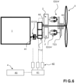
- the electric motor also comprises an electric power supply system 4 which comprises a battery 40 for powering the electric motor 2.
- a reduction system for example with an epicyclic gear train as presented below, allows the propeller to be driven at a lower speed, for example of the order of 2000 revolutions/minute.
- the electrical power supply system 4 also includes an electrical management system 41, 42 which includes a high-voltage box 41 which makes it possible to open or close the power supply circuit between the battery 40 and the electric motor 2.
- the electrical power supply system 4 also includes a controller 42 which makes it possible to process the current supplied by the battery 40 or produced by the electric motor 2 when it operates as a generator.
- the controller 42 can thus transform the direct current from the battery 40 into alternating current, for example by chopping it to power the electric motor 2, and conversely to transform the alternating current produced by the electric motor 2 into direct current to enable the battery 40 to be recharged, when the electric motor 2 operates as a generator, in particular when, as explained below, the rotor of the electric motor 2 is driven by the heat engine 1 or the propeller 3.
- the clutch system of the powertrain has a configuration making it possible to drive the electric motor 2 for recharging the battery 40, when the propeller 3 is driven by wind (or hydroelectric) effect.
- the clutch system may include friction or dog type clutches.
- the power unit comprises an intermediate shaft A2.
- the intermediate shaft A2 is interposed between the output shaft 1 and the propeller shaft A3. Furthermore, the intermediate shaft A2 is housed in the rotor 202.
- the shaft A2 can be secured (coupled) in rotation with the propeller shaft A3 by means of the clutch E23.
- the shaft A2 corresponds to a portion of said propeller shaft A3.
- the clutch system comprises a clutch E123 which, in the closed state, transmits the rotation of the thermal engine 1 to the intermediate shaft A2. In the open state of the clutch E123, the rotation of the thermal engine 1 is no longer transmitted to the intermediate shaft A2.
- the clutch E123 is located between the output shaft A1 of the thermal engine and the intermediate shaft A2.
- the clutch system also comprises a clutch E324 which, in the closed state, transmits the rotation of the electric motor 2, in particular of the rotor 202, to the propeller 3.
- a clutch E324 which, in the closed state, transmits the rotation of the electric motor 2, in particular of the rotor 202, to the propeller 3.
- the rotor 202 In the open state of the clutch E324, the rotor 202 is no longer coupled in rotation to the propeller 3, or propeller shaft A3 (in particular when the clutch E14 and/or E23 is open).
- the clutch system comprises the clutch E23 which, in the closed state, allows the rotation of the intermediate shaft A2 to be transmitted to the propeller shaft A3, preferably with a reduction system.
- the clutch E23 makes it possible to transmit to the propeller shaft A3 the rotation of the intermediate shaft A2 which comes from the rotation of the output shaft A1, in the closed state of the clutch E123, and/or which comes from the rotation of the rotor 202 in the closed state of the clutch E14.
- the clutch system comprises a clutch E14, a first part of which is, in the closed state of the first clutch E123, integral in rotation with the output shaft A1 of the heat engine 1. Said first part of the clutch E14 is mounted integral in rotation of a part of the intermediate shaft A2. A second part of the clutch E14 is mounted so as to rotate with the rotor 202 of the electric motor 2.
- the clutch E324 has a part which is coupled (in rotation) to the rotor 202 of the electric motor 2 by means of a mechanical transmission system with gears S3, S223, C213, and the other part of which is integral in rotation with the propeller 3 (or propeller shaft).
- said other part is mounted integral with the base of the nose of the propeller 3, also called the propeller plate.
- the clutch E324 thus makes it possible to transmit the rotation of the rotor 202 of the electric motor 2 to the propeller 3 (or to the propeller shaft A3 which is integral with the propeller).
- the clutch E324 allows the electric motor 2 to be driven by the propeller 3 when the latter is driven by the external flow to which it is subjected (wind or hydroelectric effect).
- the mechanical transmission system S3, S223, C213 is a meshing transmission system.
- the transmission system is preferably of the epicyclic gear train type.
- the epicyclic gear train comprises an inner shaft S3, called a sun, corresponding to a portion of the rotor 202 of the electric motor 2, and a crown C213 carried by the inside of the hollow body of the stator 201 (presented below) and a satellite S223 interposed between the sun S3 and the crown C213.
- the satellite S223 is secured to a planet carrier which is coaxial with the propeller shaft A3.
- the end of the planet carrier opposite the satellite S223 is mounted so as to rotate securely with a portion of the clutch E324.
- the E23 clutch comprises a part coupled (in rotation) to the intermediate shaft A2 by the mechanical gear transmission system S2, S23, C223 and another part integral in rotation with the propeller shaft A3.
- the mechanical transmission system S2, S23, C223 is a meshing transmission system.
- the transmission system is preferably of the epicyclic gear train type.
- the epicyclic gear train comprises an inner shaft S2, called a sun, corresponding to a portion of the intermediate shaft 2 and a crown C223 carried by the inside of the hollow body of the rotor.
- a satellite S23 is interposed between the sun S2 and the crown C223.
- the satellite S23 is secured to a planet carrier which is coaxial with the intermediate shaft A2 and the propeller shaft A3.
- the end of the planet carrier opposite the satellite S23 is rotationally secured to a portion of the clutch E23.
- the electric motor 2 comprises a stator 201 and a rotor 202.
- the stator 201 has a hollow body provided with a winding 21 on its internal face.
- the stator 201 is a part of the casing 190.
- the rotor 202 has a body rotatable about the (longitudinal) axis of the intermediate shaft A2 and inside the stator 201. Depending on the configuration state of the clutch system, the rotor can rotate about the intermediate shaft A2, relative to said intermediate shaft, or rotate with said intermediate shaft A2 about said (longitudinal) axis of the intermediate shaft A2.
- the rotor 202 is provided with magnets 22 on its external peripheral face.
- the rotational drive of the intermediate shaft A2 by the output shaft A1 of the motor 1 or by the rotation of the rotor 202 of the electric motor 2, makes it possible to rotate the satellite S23 and thus the satellite carrier coupled to the clutch E23. Closing the clutch E23 makes it possible to transmit this rotation to the propeller shaft A3 for the rotational drive of the propeller 3.
- the closing of the clutch E324 makes it possible to transmit the rotational movement between the rotor 202 of the electric motor 2 and the propeller 3.
- the clutch system E123, E14, E23, E324 is also configured to have a configuration according to which the propeller 3, set in rotation by wind or hydroelectric effect, transmits its rotational movement to the electric motor 2 to generate an electric current making it possible to recharge the battery 40.
- one of the clutches E14, E324 is open, while the other clutch E324, E14 is closed.
- one or each of the parts of a clutch mounted so as to rotate integrally with a shaft is slidably mounted, for example using grooves, on said shaft to move from a closed position to an open position and vice versa.
- the powertrain presented above makes it possible to implement different aircraft control processes by adapting the configuration of the clutches.
- the powertrain allows electric propulsion of the aircraft.
- the clutches are brought into the following configuration.
- Clutch E123 is open to release the heat engine 1 relative to the propeller 3.
- Clutch E14 and clutch E23 are preferably open.
- Clutch E324 is closed to transmit the motion of the electric motor 2 to the propeller 3.
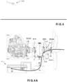
- the arrow shows that the rotational motion of the rotor 202 of the electric motor 2, electrically powered by the battery 40, is transmitted to the propeller 3 by the clutch E324.
- the powertrain In the event of a breakdown occurring in the electric transmission chain, the powertrain allows the use of thermal propulsion without using the electric motor.
- the clutches can be brought into a configuration in which the clutch E123 and the clutch E23 are closed to transmit the motion of the heat engine 1 to the propeller 3.
- the motion of the heat engine 1 is transmitted to the propeller 3 by the shafts A1, A2 and A3.
- clutch E14 and clutch E324 are open to prevent rotor 202 of electric motor 2 from rotating.
- the arrow shows that heat engine 1 transmits its rotational motion to propeller 3 via clutches E123 and E23.
- a breakdown can result, for example, from overheating of the battery or from a malfunction of a component in the electric drive chain. As a result, the rotor of the electric motor no longer turns.
- Such a clutch configuration which allows the propeller to be driven by the thermal engine alone, i.e. without input from the electric motor, can also be used during a normal take-off to conserve the charge of the electric battery or when the latter is discharged.
- Such a clutch configuration can also be used during level flight of the aircraft when the battery is considered sufficiently charged and it is desired to conserve its charge.
- the powertrain also makes it possible to combine the rotational motion provided by the heat engine and the rotational motion provided by the electric motor to drive the propeller.
- the clutches can be brought into the following configuration illustrated in Figure 2C .
- Clutch E123 is closed, clutch E14 is open, clutch E23 is closed to transmit the motion of the heat engine 1 to the propeller 3 and the clutch E324 is closed to transmit the motion of the electric motor 2 to the propeller 3.
- the arrows show that the heat engine transmits its rotational motion to the propeller via the clutches E123 and E23, while the rotational motion of the rotor 202 of the electric motor 2 supplied with current by the battery 40 is transmitted to the propeller by the clutch E324.
- the powertrain also makes it possible to recharge the battery 40 using the heat engine 1 while maintaining rotational drive of the propeller 3.
- the clutches can be brought into the following configuration.
- Clutch E324 is open.
- Clutch E123, clutch E14 and clutch E23 are closed.
- the heat engine 1 drives the intermediate shaft A2, which rotates the rotor 202 provided with the magnets 22 opposite the winding 21 of the stator 201 and thus generates a current in the winding 21, while driving the propeller shaft A3.
- the electrical management system 41, 42 controls the current produced by the rotation of the rotor 202 in order to recharge the battery 40.
- Such a mode of operation of the powertrain makes it possible to use the surplus power of the thermal engine 1 to recharge the battery 40 in flight, in particular when the battery has been used for electric propulsion during the taxiing, take-off and/or climb phase.
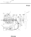
- the powertrain allows energy recovery by wind or hydroelectric effect.
- the clutches can be brought into the following configuration.
- Clutch E123 and clutch E14 are open to decouple the propeller 3 from the heat engine 1 and to decouple the rotor 202 from the heat engine 1.
- clutch E23 is open.
- Clutch E324 is closed. The arrow thus shows that the movement of the propeller 3 is transmitted to the rotor 202 of the electric motor 2 via the satellite S223 and the sun S3 and that the current thus generated is used to recharge the battery 40.
- the powertrain allows the battery 40 to be recharged using the heat engine 1 without driving the propeller 3.
- the clutches can be brought into the following configuration. Clutch E324 and clutch E23 are open. Clutch E123 and clutch E14 are closed.
- the heat engine 1 drives the intermediate shaft A2 to rotate the rotor 202 provided with the magnets 22 opposite the winding 21 of the stator 201 in order to generate a current that the electrical management system 41, 42 controls to recharge the battery 40.
- the aircraft comprises wheels equipped with an electric motor connected to the power supply battery 40 of the aircraft via an electrical management system 41, 42.
- the powertrain makes it possible to power the electric motor of the wheels by the electric battery 40.
- the electric wheel motor management system may be the same as the one that also manages the power supply to the aircraft's electric motor or may be a separate management system, interposed between the battery and the electric wheel motor.
- the heat engine 1 can be switched off or can be running at idle while waiting to be used. In particular in the case where the heat engine is switched on, each of the clutches E23 and E324 is disengaged so as not to drive the propeller.
- the powertrain comprises a clutch E123, for example friction, between said heat engine 1 and the intermediate shaft A2.
- the propeller shaft A3 is integral with the intermediate shaft A2.
- a part of the clutch E123 is rotationally coupled to the output shaft A1 of the heat engine 1 and the other part of the clutch E123 is rotationally coupled to a part of the intermediate shaft A2.
- the intermediate shaft A2 is in two parts axially offset from each other.
- the two parts of the intermediate shaft A2 are connected to each other by a transmission device T12 with pulleys and belt.
- the electric motorization may comprise one or more electric motors 2 offset axially relative to the propeller shaft A3.
- a "radial" offset could also be provided with a right-angle gear system, and on each electric motor output shaft a dog clutch or clutch system.
- Each electric motor 2 is connected to the electric power supply system 4.
- a controller 42 is provided for each electric motor 2.
- each electric motor 2 is rotationally secured to a part of a clutch E324', preferably of the dog type.
- the other part of the clutch E324' is rotationally secured to a transmission system T23, for example with pulleys and belt, arranged to transmit the rotational movement of the electric motor to the propeller shaft A3.
- Each E324' clutch makes it possible to decouple the associated electric motor 2 from the T23 transmission system, in particular in the event of failure of said or each of said electric motors.
- each electric motor 2 is provided with an independent friction or dog clutch system E324', which can be functionally assimilated to the clutch E324 of the embodiment of the Figures 1 to 5 .
- the electric motorization preferably has three or more electric motors.
- shafts of the powertrain are coaxial and the transmission of motion from one shaft is effected by means of clutches which are also coaxial.
- shafts A1 and A3 are axially offset.
- propeller shaft A3 can be driven by the electric motor in the closed state of the or each 'clutch E324', and/or by the thermal engine in the closed state of the clutch E123.
- the clutch system is controlled to switch from one configuration to another by a manual or automatic control device.
- a control unit such as a computer, makes it possible to control a clutch actuation system to control the switch from one configuration to another.
- the control unit may be in the form of a processor and a data memory. in which computer instructions executable by said processor are stored, or in the form of a microcontroller.
- control unit can be implemented by instruction sets or computer modules implemented in a processor or controller or can be implemented by dedicated electronic components or FPGA or ASIC type components. It is also possible to combine computer parts and electronic parts.
- the aircraft is an airplane equipped with wheels
- one or more wheels are equipped with an electric motor, for example incorporated in the hub.
- the electric motor of each wheel can be connected to the electrical management system of the aircraft.
- the electric motor(s) of the wheels can be powered by the battery 40 using the electrical power supply system 4.
- the aircraft may include multiple auxiliary propeller propulsion systems that can be controlled independently of each other.
- the aircraft may comprise two auxiliary propeller engines (preferably lateral) and between the two propeller engines, the propeller propulsion system of the powertrain according to the invention.
- auxiliary engines and the powertrain may be of either the tractive or propulsive type.
- the propeller or propellers have variable pitch and can be put into a so-called flag configuration to reduce drag when not in use.
Landscapes
- Engineering & Computer Science (AREA)
- Aviation & Aerospace Engineering (AREA)
- Mechanical Engineering (AREA)
- Chemical & Material Sciences (AREA)
- Combustion & Propulsion (AREA)
- Connection Of Motors, Electrical Generators, Mechanical Devices, And The Like (AREA)
- Hybrid Electric Vehicles (AREA)
- Electric Propulsion And Braking For Vehicles (AREA)
- Transmission Devices (AREA)
Claims (15)
- Maschine (100), wie beispielsweise ein Flugzeug, die mit einem Antriebsaggregat versehen ist, das Folgendes umfasst:- einen Verbrennungsmotorantrieb, umfassend einen Verbrennungsmotor (1) und eine Welle (A1), die als Abtriebswelle des Verbrennungsmotors bezeichnet wird und durch den Verbrennungsmotor in Drehung versetzt werden kann;- einen elektrischen Motorantrieb, umfassend einen Elektromotor (2);- ein Stromversorgungssystem (4), umfassend eine Batterie (40), die es ermöglicht, den Elektromotor (2) zu versorgen;- ein Propellerantriebssystem, umfassend einen Propeller (3) und eine Welle (A3), die als Propellerwelle bezeichnet wird, an die der Propeller (3) gekoppelt ist;das Antriebsaggregat auch umfassend ein Kupplungssystem (E123, E14, E23, E324) umfasst, das konfiguriert ist, um selektiv Folgendes zu ermöglichen:- Antreiben des Propellers (3) mittels des Verbrennungsmotors (1) ohne Übertragung der Drehung des Elektromotors (2) auf den Propeller (3);- Antreiben des Propellers (3) mittels des Elektromotors (2) ohne Übertragung der Drehung des Verbrennungsmotors (1) auf den Propeller (3);- Antreiben des Propellers (3) durch kombinierte Übertragung der Drehbewegung des Verbrennungsmotors (1) auf den Propeller (3) und der Drehbewegung des Elektromotors (2) auf den Propeller (3);das Antriebsaggregat umfassend eine Welle (A2) umfasst, die als Zwischenwelle bezeichnet wird, die fest mit der Propellerwelle (A3) verbunden oder drehbar damit koppelbar ist,und das Kupplungssystem umfassend:- eine erste Kupplung (E123), die konfiguriert ist, um in dem geschlossenen Zustand die Drehung des Verbrennungsmotors (1) auf die Zwischenwelle (A2) zu übertragen, und- eine zweite Kupplung (E23), die konfiguriert ist, um in dem geschlossenen Zustand die Drehung der Zwischenwelle (A2) auf die Propellerwelle (A3) zu übertragen, und eine dritte Kupplung (E324), die konfiguriert ist, um in dem geschlossenen Zustand die Drehung des Elektromotors (2) auf die Propellerwelle (A3) zu übertragen;der Elektromotor (2) umfassend einen Stator (201) und einen Rotor (202), wobei der Rotor einen Hohlkörper aufweist und drehbar um die Zwischenwelle (A2) und im Inneren des Stators (201) montiert ist, wobei der Rotor (202) und die Zwischenwelle (A2) koaxial sind.
- Maschine (100) nach Anspruch 1, wobei jede Welle (A1, A2), die einen Teil der Bewegungsübertragungskette der Bewegung auf den Propeller (3) bildet, koaxial zu der Propellerwelle (A3) ist.
- Maschine (100) nach Anspruch 1 oder 2, wobei der Stator (201) in Form eines Hohlkörpers vorliegt und mit einer Wicklung (21) versehen ist, und der Rotor (202) mit Magneten (22) versehen ist.
- Maschine (100) nach einem der Ansprüche 1 bis 3, wobei das Antriebsaggregat auch ein mechanisches Übertragungssystem (S2, S23, C223) vom Typ Planetengetriebe umfasst, das Folgendes umfasst:- eine innere Welle (S2), die als Sonne bezeichnet wird, die einem Teil der Zwischenwelle (2) entspricht, und einen Kranz (C223), der von der Innenseite des Hohlkörpers des Rotors getragen wird;- einen Satelliten (S23), der zwischen die Sonne (S2) und den Kranz (C223) ein gefügt ist, und einen Satellitenträger, dessen Ende gegenüber dem Satelliten (S23) drehfest mit einem Teil der zweiten Kupplung (E23) verbunden ist, die zweite Kupplung (E23) umfassend einen anderen Teil, der drehfest mit der Propellerwelle (A3) verbunden ist.
- Maschine (100) nach einem der Ansprüche 1 bis 4, wobei das Kupplungssystem eine vierte Kupplung (E14) umfasst, die konfiguriert ist, um in dem geschlossenen Zustand die Drehung des Verbrennungsmotors (1) auf den Elektromotor (2) zu übertragen, um diesen als Generator zu betreiben.
- Maschine (100) nach Anspruch 5, wobei die vierte Kupplung (E14) einen Teil, der in dem geschlossenen Zustand der ersten Kupplung (E123) drehfest mit der Abtriebswelle (A1) des Verbrennungsmotors (1) verbunden ist, und einen anderen Teil, der drehfest mit dem Rotor (202) des Elektromotors (2) montiert ist, umfasst.
- Maschine (100) nach einem der Ansprüche 1 bis 6, wobei die dritte Kupplung (E324) einen Teil, der über ein mechanisches Übertragungssystem (S3, S223, C213) drehfest mit dem Rotor (202) des Elektromotors (2) verbunden ist, und einen Teil, der drehfest mit dem Propeller (3) verbunden ist, umfasst.
- Maschine (100) nach einem der Ansprüche 1 bis 6, wobei das Stromversorgungssystem (4) auch ein elektrisches Managementsystem (41, 42) aufweist, das Folgendes umfasst:- einen Hochspannungskasten (41), der es ermöglicht, den Stromkreis zwischen der Batterie (40) und dem Elektromotor (2) zu öffnen oder zu schließen;- eine Steuerung (42), die es ermöglicht, den Strom zu verarbeiten, der von der Batterie (40) bereitgestellt oder von dem Elektromotor (2) erzeugt wird, wenn er als Generator betrieben wird.
- Verfahren zur Steuerung einer Maschine (100) gemäß einem der Ansprüche 5 bis 6, dadurch gekennzeichnet, dass das Steuerungsverfahren einen Schritt des elektrischen Antriebs umfasst, insbesondere während einer Start- und/oder Steigphase, wobei die Kupplungen in die folgende Konfiguration gebracht werden:- die erste Kupplung (E123) ist geöffnet, um den Verbrennungsmotor in Bezug auf den Propeller (3) freizugeben;- die vierte Kupplung (E14) und die zweite Kupplung (E23) sind vorzugsweise geöffnet sind;- die dritte Kupplung (E324) ist geschlossen, um die Bewegung des Elektromotors (2) auf den Propeller (3) zu übertragen.
- Steuerungsverfahren einer Maschine (100) nach einem der Ansprüche 1 bis 8, wobei das Steuerungsverfahren einen Schritt eines thermischen Antriebs ohne Verwendung des elektrischen Antriebs umfasst, beispielsweise wenn ein Fehler in der elektrischen Antriebskette auftritt, wobei die Kupplungen in die folgende Konfiguration gebracht werden:- die erste Kupplung (E123) ist geschlossen;- die zweite Kupplung (E23) ist geschlossen, um die Bewegung des Verbrennungsmotors (1) auf den Propeller (3) zu übertragen.
- Steuerungsverfahren einer Maschine (100) nach einem der Ansprüche 5 bis 6, wobei das Steuerungsverfahren einen Schritt eines Antriebs durch kumulativen Nutzung des Verbrennungsmotors (1) und des Elektromotors (2) umfasst, wobei die Kupplungen in die folgende Konfiguration gebracht werden:- die erste Kupplung (E123) ist geschlossen;- die zweite Kupplung (E23) ist geschlossen, um die Bewegung des Verbrennungsmotors (1) auf den Propeller (3) zu übertragen;- die dritte Kupplung (E324) ist geschlossen, um die Bewegung des Elektromotors (2) auf den Propeller (3) zu übertragen;- die vierte Kupplung (E14) ist geöffnet.
- Steuerungsverfahren einer Maschine (100) nach Anspruch 5 oder 6, wobei das Steuerungsverfahren einen Schritt zum Aufladen der Batterie (40) mittels des Verbrennungsmotors (1) unter Beibehaltung eines Drehantriebs des Propellers (3) umfasst, beispielsweise für ein Aufladen der Maschine während des Flugs, wobei die Kupplungen in die folgende Konfiguration gebracht werden:die erste Kupplung (E123), die vierte Kupplung (E14) und die zweite Kupplung (E23) sind geschlossen sind, sodass der Verbrennungsmotor (1) die Zwischenwelle (A2) antreibt, um den Rotor (202) in Bezug auf den Stator (201) zu drehen, um einen Strom zu erzeugen, während er die Propellerwelle (A3) antreibt;und dass das elektrische Managementsystem (41, 42) den Strom steuert, der von dem als Generator betriebenen Elektromotor (2) erzeugt wird, um die Batterie (40) aufzuladen.
- Steuerungsverfahren einer Maschine (100) nach Anspruch 5 oder 6, wobei das Steuerungsverfahren einen Schritt einer Energierückgewinnung durch Wind- oder Wasserkraft umfasst, wobei die Kupplungen in die folgende Konfiguration gebracht werden:- mindestens eine von der ersten Kupplung (E123) und der vierten Kupplung (E14) ist geöffnet ist, um den Propeller (3) in Bezug auf den Verbrennungsmotor (1) zu entkoppeln oder den Rotor (202) in Bezug auf den Verbrennungsmotor (1) zu entkoppeln;- vorzugsweise wobei die zweite Kupplung (E23) geöffnet ist;- die dritte Kupplung (E324) ist geschlossen ist, um die Bewegung des Propellers (3) auf den Rotor (202) des Elektromotors (2) zu übertragen.
- Steuerungsverfahren einer Maschine (100) nach Anspruch 5 oder 6, wobei das Steuerungsverfahren einen Schritt zum Aufladen der Batterie (40) mittels des Verbrennungsmotors (1) umfasst, ohne den Propeller (3) anzutreiben, wobei die Kupplungen in die folgende Konfiguration gebracht werden:- Öffnen der dritten Kupplung (E324) und der zweiten Kupplung (E23),- Schließen der ersten Kupplung (E123) und der vierten Kupplung (E14),sodass der Verbrennungsmotor (1) die Zwischenwelle (A2) antreibt, um den Rotor (202) zu drehen, um einen Strom zu erzeugen,und dass das elektrische Managementsystem (41, 42) den Strom steuert, der von dem als Generator betriebenen Elektromotor (2) erzeugt wird, um die Batterie (40) aufzuladen.
- Steuerungsverfahren nach einem der Ansprüche 9 bis 14 einer Maschine (100) nach einem der Ansprüche 1 bis 8, die Maschine umfassend Räder, die mit einem elektrischen Motorantrieb versehen sind, der über ein elektrisches Managementsystem (41, 42) zur Versorgung der Maschine mit der Batterie (40) verbunden ist, wobei das Verfahren die Versorgung des elektrischen Motorantriebs der Räder durch die elektrische Batterie (40) umfasst.
Applications Claiming Priority (2)
| Application Number | Priority Date | Filing Date | Title |
|---|---|---|---|
| FR1801092A FR3087421B1 (fr) | 2018-10-17 | 2018-10-17 | Engin comprenant un groupe motopropulseur hybride et procede de pilotage correspondant |
| PCT/FR2019/052456 WO2020079369A1 (fr) | 2018-10-17 | 2019-10-16 | Engin comprenant un groupe motopropulseur hybride et procede de pilotage correspondant |
Publications (4)
| Publication Number | Publication Date |
|---|---|
| EP3867152A1 EP3867152A1 (de) | 2021-08-25 |
| EP3867152B1 true EP3867152B1 (de) | 2024-12-25 |
| EP3867152C0 EP3867152C0 (de) | 2024-12-25 |
| EP3867152B8 EP3867152B8 (de) | 2025-02-19 |
Family
ID=65243647
Family Applications (1)
| Application Number | Title | Priority Date | Filing Date |
|---|---|---|---|
| EP19808629.0A Active EP3867152B8 (de) | 2018-10-17 | 2019-10-16 | Motor mit hybridantrieb und entsprechendes steuerungsverfahren |
Country Status (15)
| Country | Link |
|---|---|
| US (1) | US12030654B2 (de) |
| EP (1) | EP3867152B8 (de) |
| JP (1) | JP7495928B2 (de) |
| KR (1) | KR102658150B1 (de) |
| CN (1) | CN112805218B (de) |
| AU (1) | AU2019361306B2 (de) |
| CA (1) | CA3131899A1 (de) |
| ES (1) | ES3013789T3 (de) |
| FR (1) | FR3087421B1 (de) |
| IL (1) | IL281907B2 (de) |
| MX (1) | MX2021004414A (de) |
| PL (1) | PL3867152T3 (de) |
| RU (1) | RU2761151C1 (de) |
| SG (1) | SG11202103308SA (de) |
| WO (1) | WO2020079369A1 (de) |
Families Citing this family (25)
| Publication number | Priority date | Publication date | Assignee | Title |
|---|---|---|---|---|
| WO2020137103A1 (ja) * | 2018-12-27 | 2020-07-02 | 本田技研工業株式会社 | 飛行体 |
| WO2020137104A1 (ja) * | 2018-12-27 | 2020-07-02 | 本田技研工業株式会社 | 飛行体 |
| US11732639B2 (en) * | 2019-03-01 | 2023-08-22 | Pratt & Whitney Canada Corp. | Mechanical disconnects for parallel power lanes in hybrid electric propulsion systems |
| NO348387B1 (no) * | 2019-12-16 | 2024-12-23 | Lars Harald Heggen | Hybridsystem for droner og andre typer fremkomstmidler |
| US12006056B2 (en) * | 2020-10-29 | 2024-06-11 | Hybrid Project Llc | Dual drive hybrid electric power plant for aircraft |
| KR20220092064A (ko) | 2020-12-24 | 2022-07-01 | 현대자동차주식회사 | 비행체의 보조 추진 장치 |
| US12030651B2 (en) | 2021-01-05 | 2024-07-09 | Pratt & Whitney Canada Corp. | Parallel hybrid power plant with hollow motor |
| EP4294727A4 (de) | 2021-02-21 | 2025-02-12 | Verdego Aero, Inc. | Flexible architektur für ein hybridsystem für luft- und raumfahrt und optimierte komponenten davon |
| BR112023016761A2 (pt) | 2021-03-19 | 2023-10-31 | Verdego Aero Inc | Resfriamento de ar simultâneo de múltiplos elementos de um motor de alta potência híbrido |
| CN113716054B (zh) * | 2021-09-14 | 2023-06-27 | 上海峰飞航空科技有限公司 | 动力系统控制方法及无人机控制方法 |
| CN114475115B (zh) * | 2021-12-30 | 2024-05-17 | 广州小鹏智慧充电科技有限公司 | 驱动系统和交通工具 |
| KR102490173B1 (ko) * | 2022-01-04 | 2023-01-19 | (주)창인에이비에이션 | 하이브리드 추진시스템을 이용하는 수직 이착륙 항공기 및 그 제어 방법 |
| JP2025502264A (ja) * | 2022-01-14 | 2025-01-24 | ヴェルデゴ エアロ,インコーポレイテッド | ターボファンエンジンコアを含む並列ハイブリッドパワープラント |
| WO2023211278A1 (en) * | 2022-04-27 | 2023-11-02 | Verdego Aero, Inc. | Hybrid turbofan engine with a planetary gearset for blending power between an electric output and variable-thrust bypass fan |
| US12240621B2 (en) | 2022-05-11 | 2025-03-04 | Parallel Flight Technologies, Inc. | Power module and clutch mechanism for unmanned aircraft systems |
| EP4310309B1 (de) * | 2022-07-19 | 2026-04-22 | General Electric Company | Hybrid-elektrisches antriebssystem mit einem koppler zum umschalten zwischen betriebsmodi |
| US12145738B2 (en) | 2022-08-22 | 2024-11-19 | Pratt & Whitney Canada Corp. | Multi-drive unit propulsion system for an aircraft |
| US12589897B2 (en) | 2023-08-17 | 2026-03-31 | Go Fan Yourself, Llc | Apparatus and method for capturing energy from a vorticular ventilator system to utilize the energy to charge a power source |
| US20250145271A1 (en) * | 2023-11-02 | 2025-05-08 | Textron Aviation Inc. | Aircraft with Hybrid Power Supply and Unobstructed Cabin Door Access |
| US20250242928A1 (en) * | 2024-01-26 | 2025-07-31 | Pratt & Whitney Canada Corp. | Hybrid aircraft power plant and gearbox therefor |
| US20250250015A1 (en) * | 2024-02-05 | 2025-08-07 | Pratt & Whitney Canada Corp. | Hybrid aircraft power plant and method of operation |
| US12187444B1 (en) | 2024-02-06 | 2025-01-07 | Pratt & Whitney Canada Corp. | Hybrid aircraft power plant |
| WO2025239948A2 (en) * | 2024-05-17 | 2025-11-20 | Archer Aviation Inc. | Motor gearbox assembly with layshaft for evtol aircraft |
| EP4691912A1 (de) * | 2024-08-08 | 2026-02-11 | Go Fan Yourself, LLC | Vorrichtung und verfahren zur erfassung von energie aus einem drohnenpropellersystem zur verwendung der energie zum laden einer batterie |
| CN121158202A (zh) * | 2025-11-12 | 2025-12-19 | 南昌航空大学 | 一种具有动能回收功能的垂直起降飞行器 |
Citations (1)
| Publication number | Priority date | Publication date | Assignee | Title |
|---|---|---|---|---|
| EP2964524B1 (de) * | 2013-03-05 | 2018-06-27 | Embry-Riddle Aeronautical University | Hybrid-flugzeug und betriebsverfahren während des fluges |
Family Cites Families (25)
| Publication number | Priority date | Publication date | Assignee | Title |
|---|---|---|---|---|
| US7445178B2 (en) | 2004-09-28 | 2008-11-04 | The Boeing Company | Powered nose aircraft wheel system |
| US20060137355A1 (en) * | 2004-12-27 | 2006-06-29 | Pratt & Whitney Canada Corp. | Fan driven emergency generator |
| DE102007055336A1 (de) * | 2007-01-15 | 2008-08-21 | GIF Gesellschaft für Industrieforschung mbH | Flugzeugpropellerantrieb, Verfahren zum Antreiben eines Flugzeugpropellers und Verwendung eines Lagers eines Flugzeugpropellerantriebs sowie Verwendung einer Elektromaschine |
| DE102007017332A1 (de) * | 2007-04-11 | 2008-10-16 | Flight - Design - GmbH Flugsportgeräte | Luftfahrzeug |
| US8088030B2 (en) * | 2008-12-01 | 2012-01-03 | GM Global Technology Operations LLC | Electrically variable transmission with modular construction |
| GB0903423D0 (en) * | 2009-03-02 | 2009-04-08 | Rolls Royce Plc | Variable drive gas turbine engine |
| JP4981993B2 (ja) | 2009-06-12 | 2012-07-25 | 株式会社ユニバンス | 動力伝達装置 |
| US9085358B2 (en) | 2010-03-17 | 2015-07-21 | Borealis Technical Limited | Electric motor integrated with a wheel |
| US9102326B2 (en) | 2012-03-05 | 2015-08-11 | Embry-Riddle Aeronautical University, Inc. | Hybrid assembly for an aircraft |
| FR2992630B1 (fr) * | 2012-06-29 | 2015-02-20 | Turbomeca | Procede et configuration d'apport d'energie propulsive et/ou non propulsive dans une architecture d'helicoptere par un moteur auxiliaire de puissance |
| CA2820254C (en) * | 2012-07-09 | 2020-02-18 | Mcmaster University | Hybrid powertrain system |
| FR2993727B1 (fr) * | 2012-07-19 | 2017-07-21 | Eurocopter France | Machine electrique reversible pour aeronef |
| DE102012021340A1 (de) * | 2012-10-31 | 2014-04-30 | Eads Deutschland Gmbh | Bausatz und Herstellverfahren zum Herstellen eines unbemannten Luftfahrzeugs sowie damit hergestelltes unbemanntes Luftfahrzeug |
| US10094295B2 (en) * | 2013-01-30 | 2018-10-09 | Pratt & Whitney Canada Corp. | Gas turbine engine with transmission |
| WO2015073084A1 (en) | 2013-08-20 | 2015-05-21 | The Regents Of The University Of Colorado, A Body Corporate | Hybrid co-axial shaft in shaft transmission using planetary gear set for multiple sources of torque |
| FR3029172B1 (fr) * | 2014-11-27 | 2018-05-25 | Safran Helicopter Engines | Groupe propulseur a moyens d'accouplement selectif |
| DE102014224637B4 (de) * | 2014-12-02 | 2022-12-29 | Georgi Atanasov | Hybrid-Elektro-Antriebssystem für ein Flugzeug |
| FR3039614B1 (fr) * | 2015-07-31 | 2018-05-04 | Airbus Helicopters | Installation motrice hybride pour aeronef a voilure tournante bimoteur |
| US10502188B2 (en) | 2016-03-30 | 2019-12-10 | Lockheed Martin Corporation | Wind-powered recharging for a weight-shifting coaxial helicopter |
| EP3296199B1 (de) | 2016-09-19 | 2020-04-08 | Lockheed Martin Corporation | Windbetriebenes wiederaufladen für einen gewichtsverlagernden koaxial-hubschrauber |
| US10837304B2 (en) * | 2016-12-13 | 2020-11-17 | General Electric Company | Hybrid-electric drive system |
| JP6520908B2 (ja) * | 2016-12-22 | 2019-05-29 | トヨタ自動車株式会社 | ハイブリッド車両 |
| CN108082500A (zh) | 2018-01-29 | 2018-05-29 | 吉林大学 | 一种固定翼式混合动力飞行器驱动装置及驱动方法 |
| US10968825B2 (en) * | 2018-04-19 | 2021-04-06 | The Boeing Company | Flow multiplier systems for aircraft |
| US11168616B2 (en) * | 2018-05-16 | 2021-11-09 | Raytheon Technologies Corporation | Hybrid electric fan with improved low pressure compressor |
-
2018
- 2018-10-17 FR FR1801092A patent/FR3087421B1/fr active Active
-
2019
- 2019-10-16 IL IL281907A patent/IL281907B2/en unknown
- 2019-10-16 CN CN201980065847.9A patent/CN112805218B/zh active Active
- 2019-10-16 JP JP2021517786A patent/JP7495928B2/ja active Active
- 2019-10-16 ES ES19808629T patent/ES3013789T3/es active Active
- 2019-10-16 AU AU2019361306A patent/AU2019361306B2/en active Active
- 2019-10-16 MX MX2021004414A patent/MX2021004414A/es unknown
- 2019-10-16 CA CA3131899A patent/CA3131899A1/fr active Pending
- 2019-10-16 RU RU2021111839A patent/RU2761151C1/ru active
- 2019-10-16 WO PCT/FR2019/052456 patent/WO2020079369A1/fr not_active Ceased
- 2019-10-16 US US17/278,770 patent/US12030654B2/en active Active
- 2019-10-16 SG SG11202103308SA patent/SG11202103308SA/en unknown
- 2019-10-16 PL PL19808629.0T patent/PL3867152T3/pl unknown
- 2019-10-16 EP EP19808629.0A patent/EP3867152B8/de active Active
- 2019-10-16 KR KR1020217009821A patent/KR102658150B1/ko active Active
Patent Citations (1)
| Publication number | Priority date | Publication date | Assignee | Title |
|---|---|---|---|---|
| EP2964524B1 (de) * | 2013-03-05 | 2018-06-27 | Embry-Riddle Aeronautical University | Hybrid-flugzeug und betriebsverfahren während des fluges |
Also Published As
| Publication number | Publication date |
|---|---|
| WO2020079369A1 (fr) | 2020-04-23 |
| JP7495928B2 (ja) | 2024-06-05 |
| KR20210075985A (ko) | 2021-06-23 |
| IL281907A (en) | 2021-05-31 |
| CN112805218A (zh) | 2021-05-14 |
| ES3013789T3 (en) | 2025-04-15 |
| JP2022503951A (ja) | 2022-01-12 |
| PL3867152T3 (pl) | 2025-04-28 |
| CN112805218B (zh) | 2023-12-22 |
| US20220033097A1 (en) | 2022-02-03 |
| EP3867152A1 (de) | 2021-08-25 |
| FR3087421B1 (fr) | 2022-03-04 |
| FR3087421A1 (fr) | 2020-04-24 |
| AU2019361306A1 (en) | 2021-05-20 |
| SG11202103308SA (en) | 2021-05-28 |
| IL281907B2 (en) | 2025-05-01 |
| CA3131899A1 (fr) | 2020-04-23 |
| EP3867152C0 (de) | 2024-12-25 |
| KR102658150B1 (ko) | 2024-04-16 |
| RU2761151C1 (ru) | 2021-12-06 |
| MX2021004414A (es) | 2021-07-06 |
| US12030654B2 (en) | 2024-07-09 |
| IL281907B1 (en) | 2025-01-01 |
| EP3867152B8 (de) | 2025-02-19 |
| AU2019361306B2 (en) | 2024-09-19 |
| BR112021006192A2 (pt) | 2021-06-29 |
Similar Documents
| Publication | Publication Date | Title |
|---|---|---|
| EP3867152B1 (de) | Motor mit hybridantrieb und entsprechendes steuerungsverfahren | |
| EP2750969B1 (de) | Luftfahrzeug mit aus mehreren elektromotoren mit freilauf bestehendem antrieb | |
| EP2974964B1 (de) | Elektrischer aufbau für ein luftfahrzeug, luftfahrzeug und anwendungsverfahren | |
| CA2943486C (fr) | Dispositif d'assistance pour une turbomachine a turbine libre d'un aeronef comprenant au moins deux turbomachines a turbine libre | |
| WO2020240134A1 (fr) | Engin comprenant un groupe motopropulseur hybride et procédé de pilotage correspondant | |
| FR2979614A1 (fr) | Transmission electromagnetique de puissance pour aeronef a voilure tournante ou fixe. | |
| EP4334210B1 (de) | Verbessertes getriebe für hybridflugzeuge | |
| EP3787967B1 (de) | Antriebssystem für einen hubschrauber | |
| WO2011107718A1 (fr) | Aéronef à voilure tournante ou fixe équipé d'un groupe électromoteur distribué | |
| FR3039614A1 (fr) | Installation motrice hybride pour aeronef a voilure tournante bimoteur | |
| EP4004355B1 (de) | Turbomaschine mit einer elektrischen maschine mit starter-generatorfunktion und verfahren zur regelung der drehzahl einer solchen elektrischen maschine | |
| WO2017168074A1 (fr) | Unité d'alimentation en air sous pression pour aéronef | |
| EP3659922B1 (de) | Ein flugzeug eines modularen typs und ein verfahren zur vorbereitung eines solchen flugzeugs für eine bestimmte mission | |
| FR2988073A1 (fr) | Aeronef | |
| FR3008953A1 (fr) | Aeronef a entrainement ameliore du systeme hypersustentateur | |
| EP4551428B1 (de) | Elektrischer antriebsstrang für flugzeug und verfahren zum laden einer batterie eines flugzeugs | |
| EP4313764B1 (de) | Kampfflugzeug mit elektrischem waffensystem mit optimiertem energiemanagement | |
| EP4493807A1 (de) | Verbesserte turbomaschine für ein hybridflugzeug | |
| WO2019207256A1 (fr) | Systeme de propulsion hybride pour un aeronef | |
| BR112021006192B1 (pt) | Máquina e método de controle de uma máquina |
Legal Events
| Date | Code | Title | Description |
|---|---|---|---|
| STAA | Information on the status of an ep patent application or granted ep patent |
Free format text: STATUS: UNKNOWN |
|
| STAA | Information on the status of an ep patent application or granted ep patent |
Free format text: STATUS: THE INTERNATIONAL PUBLICATION HAS BEEN MADE |
|
| PUAI | Public reference made under article 153(3) epc to a published international application that has entered the european phase |
Free format text: ORIGINAL CODE: 0009012 |
|
| STAA | Information on the status of an ep patent application or granted ep patent |
Free format text: STATUS: REQUEST FOR EXAMINATION WAS MADE |
|
| 17P | Request for examination filed |
Effective date: 20210326 |
|
| AK | Designated contracting states |
Kind code of ref document: A1 Designated state(s): AL AT BE BG CH CY CZ DE DK EE ES FI FR GB GR HR HU IE IS IT LI LT LU LV MC MK MT NL NO PL PT RO RS SE SI SK SM TR |
|
| DAV | Request for validation of the european patent (deleted) | ||
| DAX | Request for extension of the european patent (deleted) | ||
| GRAP | Despatch of communication of intention to grant a patent |
Free format text: ORIGINAL CODE: EPIDOSNIGR1 |
|
| STAA | Information on the status of an ep patent application or granted ep patent |
Free format text: STATUS: GRANT OF PATENT IS INTENDED |
|
| INTG | Intention to grant announced |
Effective date: 20221216 |
|
| GRAJ | Information related to disapproval of communication of intention to grant by the applicant or resumption of examination proceedings by the epo deleted |
Free format text: ORIGINAL CODE: EPIDOSDIGR1 |
|
| STAA | Information on the status of an ep patent application or granted ep patent |
Free format text: STATUS: REQUEST FOR EXAMINATION WAS MADE |
|
| STAA | Information on the status of an ep patent application or granted ep patent |
Free format text: STATUS: EXAMINATION IS IN PROGRESS |
|
| INTC | Intention to grant announced (deleted) | ||
| 17Q | First examination report despatched |
Effective date: 20230522 |
|
| GRAP | Despatch of communication of intention to grant a patent |
Free format text: ORIGINAL CODE: EPIDOSNIGR1 |
|
| STAA | Information on the status of an ep patent application or granted ep patent |
Free format text: STATUS: GRANT OF PATENT IS INTENDED |
|
| INTG | Intention to grant announced |
Effective date: 20240729 |
|
| GRAS | Grant fee paid |
Free format text: ORIGINAL CODE: EPIDOSNIGR3 |
|
| GRAA | (expected) grant |
Free format text: ORIGINAL CODE: 0009210 |
|
| STAA | Information on the status of an ep patent application or granted ep patent |
Free format text: STATUS: THE PATENT HAS BEEN GRANTED |
|
| GRAL | Information related to payment of fee for publishing/printing deleted |
Free format text: ORIGINAL CODE: EPIDOSDIGR3 |
|
| GRAS | Grant fee paid |
Free format text: ORIGINAL CODE: EPIDOSNIGR3 |
|
| AK | Designated contracting states |
Kind code of ref document: B1 Designated state(s): AL AT BE BG CH CY CZ DE DK EE ES FI FR GB GR HR HU IE IS IT LI LT LU LV MC MK MT NL NO PL PT RO RS SE SI SK SM TR |
|
| REG | Reference to a national code |
Ref country code: GB Ref legal event code: FG4D Free format text: NOT ENGLISH |
|
| REG | Reference to a national code |
Ref country code: CH Ref legal event code: EP |
|
| REG | Reference to a national code |
Ref country code: DE Ref legal event code: R096 Ref document number: 602019064019 Country of ref document: DE |
|
| REG | Reference to a national code |
Ref country code: DE Ref legal event code: R081 Ref document number: 602019064019 Country of ref document: DE Owner name: VOLTAERO, FR Free format text: FORMER OWNER: VOLTAERO, MEDIS, FR |
|
| RAP4 | Party data changed (patent owner data changed or rights of a patent transferred) |
Owner name: VOLTAERO |
|
| REG | Reference to a national code |
Ref country code: IE Ref legal event code: FG4D Free format text: LANGUAGE OF EP DOCUMENT: FRENCH |
|
| REG | Reference to a national code |
Ref country code: CH Ref legal event code: PK Free format text: RECTIFICATION B8 |
|
| RAP4 | Party data changed (patent owner data changed or rights of a patent transferred) |
Owner name: VOLTAERO |
|
| U01 | Request for unitary effect filed |
Effective date: 20250121 |
|
| U07 | Unitary effect registered |
Designated state(s): AT BE BG DE DK EE FI FR IT LT LU LV MT NL PT RO SE SI Effective date: 20250128 |
|
| PG25 | Lapsed in a contracting state [announced via postgrant information from national office to epo] |
Ref country code: HR Free format text: LAPSE BECAUSE OF FAILURE TO SUBMIT A TRANSLATION OF THE DESCRIPTION OR TO PAY THE FEE WITHIN THE PRESCRIBED TIME-LIMIT Effective date: 20241225 |
|
| REG | Reference to a national code |
Ref country code: ES Ref legal event code: FG2A Ref document number: 3013789 Country of ref document: ES Kind code of ref document: T3 Effective date: 20250415 |
|
| PG25 | Lapsed in a contracting state [announced via postgrant information from national office to epo] |
Ref country code: GR Free format text: LAPSE BECAUSE OF FAILURE TO SUBMIT A TRANSLATION OF THE DESCRIPTION OR TO PAY THE FEE WITHIN THE PRESCRIBED TIME-LIMIT Effective date: 20250326 |
|
| PG25 | Lapsed in a contracting state [announced via postgrant information from national office to epo] |
Ref country code: RS Free format text: LAPSE BECAUSE OF FAILURE TO SUBMIT A TRANSLATION OF THE DESCRIPTION OR TO PAY THE FEE WITHIN THE PRESCRIBED TIME-LIMIT Effective date: 20250325 |
|
| PGFP | Annual fee paid to national office [announced via postgrant information from national office to epo] |
Ref country code: TR Payment date: 20250318 Year of fee payment: 7 |
|
| PG25 | Lapsed in a contracting state [announced via postgrant information from national office to epo] |
Ref country code: SM Free format text: LAPSE BECAUSE OF FAILURE TO SUBMIT A TRANSLATION OF THE DESCRIPTION OR TO PAY THE FEE WITHIN THE PRESCRIBED TIME-LIMIT Effective date: 20241225 |
|
| PG25 | Lapsed in a contracting state [announced via postgrant information from national office to epo] |
Ref country code: IS Free format text: LAPSE BECAUSE OF FAILURE TO SUBMIT A TRANSLATION OF THE DESCRIPTION OR TO PAY THE FEE WITHIN THE PRESCRIBED TIME-LIMIT Effective date: 20250425 |
|
| PG25 | Lapsed in a contracting state [announced via postgrant information from national office to epo] |
Ref country code: SK Free format text: LAPSE BECAUSE OF FAILURE TO SUBMIT A TRANSLATION OF THE DESCRIPTION OR TO PAY THE FEE WITHIN THE PRESCRIBED TIME-LIMIT Effective date: 20241225 |
|
| PG25 | Lapsed in a contracting state [announced via postgrant information from national office to epo] |
Ref country code: CZ Free format text: LAPSE BECAUSE OF FAILURE TO SUBMIT A TRANSLATION OF THE DESCRIPTION OR TO PAY THE FEE WITHIN THE PRESCRIBED TIME-LIMIT Effective date: 20241225 |
|
| PGFP | Annual fee paid to national office [announced via postgrant information from national office to epo] |
Ref country code: GB Payment date: 20250916 Year of fee payment: 7 |
|
| PLBE | No opposition filed within time limit |
Free format text: ORIGINAL CODE: 0009261 |
|
| STAA | Information on the status of an ep patent application or granted ep patent |
Free format text: STATUS: NO OPPOSITION FILED WITHIN TIME LIMIT |
|
| REG | Reference to a national code |
Ref country code: CH Ref legal event code: U11 Free format text: ST27 STATUS EVENT CODE: U-0-0-U10-U11 (AS PROVIDED BY THE NATIONAL OFFICE) Effective date: 20251101 |
|
| 26N | No opposition filed |
Effective date: 20250926 |
|
| U20 | Renewal fee for the european patent with unitary effect paid |
Year of fee payment: 7 Effective date: 20251030 |
|
| PGFP | Annual fee paid to national office [announced via postgrant information from national office to epo] |
Ref country code: NO Payment date: 20251023 Year of fee payment: 7 |
|
| PGFP | Annual fee paid to national office [announced via postgrant information from national office to epo] |
Ref country code: CH Payment date: 20251101 Year of fee payment: 7 |
|
| PGFP | Annual fee paid to national office [announced via postgrant information from national office to epo] |
Ref country code: PL Payment date: 20251021 Year of fee payment: 7 |
|
| PGFP | Annual fee paid to national office [announced via postgrant information from national office to epo] |
Ref country code: ES Payment date: 20251104 Year of fee payment: 7 |