EP3867152B1 - Engin comprenant un groupe motopropulseur hybride et procédé de pilotage correspondant - Google Patents
Engin comprenant un groupe motopropulseur hybride et procédé de pilotage correspondant Download PDFInfo
- Publication number
- EP3867152B1 EP3867152B1 EP19808629.0A EP19808629A EP3867152B1 EP 3867152 B1 EP3867152 B1 EP 3867152B1 EP 19808629 A EP19808629 A EP 19808629A EP 3867152 B1 EP3867152 B1 EP 3867152B1
- Authority
- EP
- European Patent Office
- Prior art keywords
- clutch
- propeller
- electric motor
- rotation
- shaft
- Prior art date
- Legal status (The legal status is an assumption and is not a legal conclusion. Google has not performed a legal analysis and makes no representation as to the accuracy of the status listed.)
- Active
Links
Images


Classifications
-
- B—PERFORMING OPERATIONS; TRANSPORTING
- B64—AIRCRAFT; AVIATION; COSMONAUTICS
- B64U—UNMANNED AERIAL VEHICLES [UAV]; EQUIPMENT THEREFOR
- B64U50/00—Propulsion; Power supply
- B64U50/30—Supply or distribution of electrical power
- B64U50/34—In-flight charging
-
- B—PERFORMING OPERATIONS; TRANSPORTING
- B64—AIRCRAFT; AVIATION; COSMONAUTICS
- B64D—EQUIPMENT FOR FITTING IN OR TO AIRCRAFT; FLIGHT SUITS; PARACHUTES; ARRANGEMENT OR MOUNTING OF POWER PLANTS OR PROPULSION TRANSMISSIONS IN AIRCRAFT
- B64D27/00—Arrangement or mounting of power plants in aircraft; Aircraft characterised by the type or position of power plants
- B64D27/02—Aircraft characterised by the type or position of power plants
-
- B—PERFORMING OPERATIONS; TRANSPORTING
- B64—AIRCRAFT; AVIATION; COSMONAUTICS
- B64C—AEROPLANES; HELICOPTERS
- B64C27/00—Rotorcraft; Rotors peculiar thereto
- B64C27/04—Helicopters
- B64C27/12—Rotor drives
-
- B—PERFORMING OPERATIONS; TRANSPORTING
- B64—AIRCRAFT; AVIATION; COSMONAUTICS
- B64C—AEROPLANES; HELICOPTERS
- B64C39/00—Aircraft not otherwise provided for
- B64C39/02—Aircraft not otherwise provided for characterised by special use
- B64C39/024—Aircraft not otherwise provided for characterised by special use of the remote controlled vehicle type, i.e. RPV
-
- B—PERFORMING OPERATIONS; TRANSPORTING
- B64—AIRCRAFT; AVIATION; COSMONAUTICS
- B64D—EQUIPMENT FOR FITTING IN OR TO AIRCRAFT; FLIGHT SUITS; PARACHUTES; ARRANGEMENT OR MOUNTING OF POWER PLANTS OR PROPULSION TRANSMISSIONS IN AIRCRAFT
- B64D27/00—Arrangement or mounting of power plants in aircraft; Aircraft characterised by the type or position of power plants
- B64D27/02—Aircraft characterised by the type or position of power plants
- B64D27/10—Aircraft characterised by the type or position of power plants of gas-turbine type
-
- B—PERFORMING OPERATIONS; TRANSPORTING
- B64—AIRCRAFT; AVIATION; COSMONAUTICS
- B64D—EQUIPMENT FOR FITTING IN OR TO AIRCRAFT; FLIGHT SUITS; PARACHUTES; ARRANGEMENT OR MOUNTING OF POWER PLANTS OR PROPULSION TRANSMISSIONS IN AIRCRAFT
- B64D27/00—Arrangement or mounting of power plants in aircraft; Aircraft characterised by the type or position of power plants
- B64D27/02—Aircraft characterised by the type or position of power plants
- B64D27/30—Aircraft characterised by electric power plants
- B64D27/32—Aircraft characterised by electric power plants within, or attached to, fuselages
-
- B—PERFORMING OPERATIONS; TRANSPORTING
- B64—AIRCRAFT; AVIATION; COSMONAUTICS
- B64D—EQUIPMENT FOR FITTING IN OR TO AIRCRAFT; FLIGHT SUITS; PARACHUTES; ARRANGEMENT OR MOUNTING OF POWER PLANTS OR PROPULSION TRANSMISSIONS IN AIRCRAFT
- B64D27/00—Arrangement or mounting of power plants in aircraft; Aircraft characterised by the type or position of power plants
- B64D27/02—Aircraft characterised by the type or position of power plants
- B64D27/30—Aircraft characterised by electric power plants
- B64D27/33—Hybrid electric aircraft
-
- B—PERFORMING OPERATIONS; TRANSPORTING
- B64—AIRCRAFT; AVIATION; COSMONAUTICS
- B64D—EQUIPMENT FOR FITTING IN OR TO AIRCRAFT; FLIGHT SUITS; PARACHUTES; ARRANGEMENT OR MOUNTING OF POWER PLANTS OR PROPULSION TRANSMISSIONS IN AIRCRAFT
- B64D35/00—Transmitting power from power plants to propellers or rotors; Arrangements of transmissions
- B64D35/02—Transmitting power from power plants to propellers or rotors; Arrangements of transmissions specially adapted for specific power plants
- B64D35/021—Transmitting power from power plants to propellers or rotors; Arrangements of transmissions specially adapted for specific power plants for electric power plants
- B64D35/022—Transmitting power from power plants to propellers or rotors; Arrangements of transmissions specially adapted for specific power plants for electric power plants of hybrid-electric type
- B64D35/023—Transmitting power from power plants to propellers or rotors; Arrangements of transmissions specially adapted for specific power plants for electric power plants of hybrid-electric type of series-parallel type
-
- B—PERFORMING OPERATIONS; TRANSPORTING
- B64—AIRCRAFT; AVIATION; COSMONAUTICS
- B64D—EQUIPMENT FOR FITTING IN OR TO AIRCRAFT; FLIGHT SUITS; PARACHUTES; ARRANGEMENT OR MOUNTING OF POWER PLANTS OR PROPULSION TRANSMISSIONS IN AIRCRAFT
- B64D35/00—Transmitting power from power plants to propellers or rotors; Arrangements of transmissions
- B64D35/02—Transmitting power from power plants to propellers or rotors; Arrangements of transmissions specially adapted for specific power plants
- B64D35/021—Transmitting power from power plants to propellers or rotors; Arrangements of transmissions specially adapted for specific power plants for electric power plants
- B64D35/022—Transmitting power from power plants to propellers or rotors; Arrangements of transmissions specially adapted for specific power plants for electric power plants of hybrid-electric type
- B64D35/024—Transmitting power from power plants to propellers or rotors; Arrangements of transmissions specially adapted for specific power plants for electric power plants of hybrid-electric type of series type
-
- B—PERFORMING OPERATIONS; TRANSPORTING
- B64—AIRCRAFT; AVIATION; COSMONAUTICS
- B64U—UNMANNED AERIAL VEHICLES [UAV]; EQUIPMENT THEREFOR
- B64U50/00—Propulsion; Power supply
- B64U50/10—Propulsion
-
- B—PERFORMING OPERATIONS; TRANSPORTING
- B64—AIRCRAFT; AVIATION; COSMONAUTICS
- B64U—UNMANNED AERIAL VEHICLES [UAV]; EQUIPMENT THEREFOR
- B64U50/00—Propulsion; Power supply
- B64U50/30—Supply or distribution of electrical power
- B64U50/33—Supply or distribution of electrical power generated by combustion engines
-
- B—PERFORMING OPERATIONS; TRANSPORTING
- B64—AIRCRAFT; AVIATION; COSMONAUTICS
- B64D—EQUIPMENT FOR FITTING IN OR TO AIRCRAFT; FLIGHT SUITS; PARACHUTES; ARRANGEMENT OR MOUNTING OF POWER PLANTS OR PROPULSION TRANSMISSIONS IN AIRCRAFT
- B64D27/00—Arrangement or mounting of power plants in aircraft; Aircraft characterised by the type or position of power plants
- B64D27/02—Aircraft characterised by the type or position of power plants
- B64D27/026—Aircraft characterised by the type or position of power plants comprising different types of power plants, e.g. combination of a piston engine and a gas-turbine
-
- Y—GENERAL TAGGING OF NEW TECHNOLOGICAL DEVELOPMENTS; GENERAL TAGGING OF CROSS-SECTIONAL TECHNOLOGIES SPANNING OVER SEVERAL SECTIONS OF THE IPC; TECHNICAL SUBJECTS COVERED BY FORMER USPC CROSS-REFERENCE ART COLLECTIONS [XRACs] AND DIGESTS
- Y02—TECHNOLOGIES OR APPLICATIONS FOR MITIGATION OR ADAPTATION AGAINST CLIMATE CHANGE
- Y02T—CLIMATE CHANGE MITIGATION TECHNOLOGIES RELATED TO TRANSPORTATION
- Y02T50/00—Aeronautics or air transport
- Y02T50/60—Efficient propulsion technologies, e.g. for aircraft
Definitions
- the present invention generally relates to a machine, such as an aircraft, equipped with a powertrain comprising an electric motor and a heat engine.
- the powertrain comprises a propeller, an electric motor for driving the propeller, a battery for powering the electric motor, and a heat engine associated with an alternator for recharging the battery.
- the propeller can no longer be driven.
- Such a powertrain configuration therefore poses significant safety problems, particularly during take-off.
- the aim of the present invention is to propose a new device making it possible to overcome all or part of the problems set out above.
- Such a design of the machine with the rotor which is mounted coaxially and rotatably around the axis of the intermediate shaft, which is part of the motion transmission chain, makes it possible to gain in compactness and weight (by limiting the number of parts), which makes it possible to increase the ratio of power supplied (KW) / weight (Kg).
- the intermediate shaft extends inside the rotor and said intermediate shaft, which is part of the mechanical transmission line, is coaxial with the axis of rotation of the rotor.
- said intermediate shaft is also coaxial with the propeller shaft and a clutch system makes it possible to couple/decouple the intermediate shaft and the propeller shaft.
- each shaft which forms part of the motion transmission chain to the propeller is coaxial with the propeller shaft.
- the stator is in the form of a hollow body and provided with a winding, and the rotor is provided with magnets.
- the clutch system comprises a fourth clutch configured to, in the closed state, transmit rotation of the heat engine to the electric motor to make it work as a generator.
- each shaft that forms part of the motion transmission chain to the propeller shaft is coaxial with the propeller shaft.
- the stator is in the form of a hollow body provided with a winding and/or magnets, preferably on its internal face and the rotor is provided with magnets and/or a winding preferably on its external peripheral face.
- the propeller propulsion system of the machine can thus be driven independently or simultaneously, by the electric motor and/or by the thermal motor. Safety, particularly during takeoff when the machine is an aircraft, is thus improved since, in the event of a problem on the electric transmission chain, the thermal motor can take over to drive the propeller.
- the second clutch in the closed state, transmits the rotation of the intermediate shaft to the propeller shaft.
- the clutch system comprises a fourth clutch configured to, in the closed state, transmit the rotation of the heat engine to the electric motor to operate it as a generator.
- the powertrain comprises a transmission system, for example comprising a clutch, for transmitting a rotational movement between the rotor and the intermediate shaft.
- the powertrain comprises a mechanical transmission system for transmitting rotation from the intermediate shaft to the propeller shaft in the closed state of the second clutch.
- the mechanical transmission system is a reduction system.
- the mechanical transmission system is housed in the rotor.
- the mechanical transmission system comprises for example an epicyclic gear train with a part coupled to the intermediate shaft and a part coupled to a part of the second clutch, the other part of the second clutch being coupled to the propeller shaft.
- the second clutch comprises a part coupled in rotation with the intermediate shaft, for example via the mechanical transmission system, and a part coupled, preferably integral, in rotation with the propeller shaft.
- the fourth clutch comprises a part which is, in the closed state of the first clutch, rotationally secured to the output shaft of the heat engine, and another part which is mounted rotationally secured to the rotor of the electric motor.
- the third clutch comprises a part integral in rotation with the rotor of the electric motor via a mechanical transmission system, and a part integral in rotation with the propeller.
- a piloting method is provided according to any one of claims 9 to 15.
- the aircraft is for example an airplane, a drone or a helicopter.
- the aircraft 100 comprises a powertrain, also called a power module, which comprises a casing 190 and a propeller propulsion system, a thermal engine and an electric engine.
- a powertrain also called a power module
- the card 190 houses the thermal motorization, the rotor 202 of the electric motor 2, the stator 201 to be formed by a part of the casing 190.
- the power unit can also be applied to a nautical propulsion, so that the craft can be a nautical craft.
- the propeller propulsion system comprises a propeller 3 and a propeller shaft A3 to which the propeller 3 is fixed.
- the heat engine and/or the electric motor can be used to drive one or more other additional propeller propulsion systems 3' as shown diagrammatically in the figure. figure 1 .
- This type of configuration can be called “distributed propulsion”.
- the thermal engine comprises a thermal engine 1 which has an output shaft A1, driven in rotation by the thermal engine.
- the thermal engine can for example rotate at a speed of the order of 6000 revolutions/minute.
- the powertrain comprises an AM1 torque damper for correcting/smoothing out the acyclisms of the thermal engine.
- the electric motor comprises an electric motor 2.
- the electric motor 2 can rotate for example at a speed of the order of 6000 revolutions/minute.
- the electric motor also comprises an electric power supply system 4 which comprises a battery 40 for powering the electric motor 2.
- a reduction system for example with an epicyclic gear train as presented below, allows the propeller to be driven at a lower speed, for example of the order of 2000 revolutions/minute.
- the electrical power supply system 4 also includes an electrical management system 41, 42 which includes a high-voltage box 41 which makes it possible to open or close the power supply circuit between the battery 40 and the electric motor 2.
- the electrical power supply system 4 also includes a controller 42 which makes it possible to process the current supplied by the battery 40 or produced by the electric motor 2 when it operates as a generator.
- the controller 42 can thus transform the direct current from the battery 40 into alternating current, for example by chopping it to power the electric motor 2, and conversely to transform the alternating current produced by the electric motor 2 into direct current to enable the battery 40 to be recharged, when the electric motor 2 operates as a generator, in particular when, as explained below, the rotor of the electric motor 2 is driven by the heat engine 1 or the propeller 3.
- the clutch system of the powertrain has a configuration making it possible to drive the electric motor 2 for recharging the battery 40, when the propeller 3 is driven by wind (or hydroelectric) effect.
- the clutch system may include friction or dog type clutches.
- the power unit comprises an intermediate shaft A2.
- the intermediate shaft A2 is interposed between the output shaft 1 and the propeller shaft A3. Furthermore, the intermediate shaft A2 is housed in the rotor 202.
- the shaft A2 can be secured (coupled) in rotation with the propeller shaft A3 by means of the clutch E23.
- the shaft A2 corresponds to a portion of said propeller shaft A3.
- the clutch system comprises a clutch E123 which, in the closed state, transmits the rotation of the thermal engine 1 to the intermediate shaft A2. In the open state of the clutch E123, the rotation of the thermal engine 1 is no longer transmitted to the intermediate shaft A2.
- the clutch E123 is located between the output shaft A1 of the thermal engine and the intermediate shaft A2.
- the clutch system also comprises a clutch E324 which, in the closed state, transmits the rotation of the electric motor 2, in particular of the rotor 202, to the propeller 3.
- a clutch E324 which, in the closed state, transmits the rotation of the electric motor 2, in particular of the rotor 202, to the propeller 3.
- the rotor 202 In the open state of the clutch E324, the rotor 202 is no longer coupled in rotation to the propeller 3, or propeller shaft A3 (in particular when the clutch E14 and/or E23 is open).
- the clutch system comprises the clutch E23 which, in the closed state, allows the rotation of the intermediate shaft A2 to be transmitted to the propeller shaft A3, preferably with a reduction system.
- the clutch E23 makes it possible to transmit to the propeller shaft A3 the rotation of the intermediate shaft A2 which comes from the rotation of the output shaft A1, in the closed state of the clutch E123, and/or which comes from the rotation of the rotor 202 in the closed state of the clutch E14.
- the clutch system comprises a clutch E14, a first part of which is, in the closed state of the first clutch E123, integral in rotation with the output shaft A1 of the heat engine 1. Said first part of the clutch E14 is mounted integral in rotation of a part of the intermediate shaft A2. A second part of the clutch E14 is mounted so as to rotate with the rotor 202 of the electric motor 2.
- the clutch E324 has a part which is coupled (in rotation) to the rotor 202 of the electric motor 2 by means of a mechanical transmission system with gears S3, S223, C213, and the other part of which is integral in rotation with the propeller 3 (or propeller shaft).
- said other part is mounted integral with the base of the nose of the propeller 3, also called the propeller plate.
- the clutch E324 thus makes it possible to transmit the rotation of the rotor 202 of the electric motor 2 to the propeller 3 (or to the propeller shaft A3 which is integral with the propeller).
- the clutch E324 allows the electric motor 2 to be driven by the propeller 3 when the latter is driven by the external flow to which it is subjected (wind or hydroelectric effect).
- the mechanical transmission system S3, S223, C213 is a meshing transmission system.
- the transmission system is preferably of the epicyclic gear train type.
- the epicyclic gear train comprises an inner shaft S3, called a sun, corresponding to a portion of the rotor 202 of the electric motor 2, and a crown C213 carried by the inside of the hollow body of the stator 201 (presented below) and a satellite S223 interposed between the sun S3 and the crown C213.
- the satellite S223 is secured to a planet carrier which is coaxial with the propeller shaft A3.
- the end of the planet carrier opposite the satellite S223 is mounted so as to rotate securely with a portion of the clutch E324.
- the E23 clutch comprises a part coupled (in rotation) to the intermediate shaft A2 by the mechanical gear transmission system S2, S23, C223 and another part integral in rotation with the propeller shaft A3.
- the mechanical transmission system S2, S23, C223 is a meshing transmission system.
- the transmission system is preferably of the epicyclic gear train type.
- the epicyclic gear train comprises an inner shaft S2, called a sun, corresponding to a portion of the intermediate shaft 2 and a crown C223 carried by the inside of the hollow body of the rotor.
- a satellite S23 is interposed between the sun S2 and the crown C223.
- the satellite S23 is secured to a planet carrier which is coaxial with the intermediate shaft A2 and the propeller shaft A3.
- the end of the planet carrier opposite the satellite S23 is rotationally secured to a portion of the clutch E23.
- the electric motor 2 comprises a stator 201 and a rotor 202.
- the stator 201 has a hollow body provided with a winding 21 on its internal face.
- the stator 201 is a part of the casing 190.
- the rotor 202 has a body rotatable about the (longitudinal) axis of the intermediate shaft A2 and inside the stator 201. Depending on the configuration state of the clutch system, the rotor can rotate about the intermediate shaft A2, relative to said intermediate shaft, or rotate with said intermediate shaft A2 about said (longitudinal) axis of the intermediate shaft A2.
- the rotor 202 is provided with magnets 22 on its external peripheral face.
- the rotational drive of the intermediate shaft A2 by the output shaft A1 of the motor 1 or by the rotation of the rotor 202 of the electric motor 2, makes it possible to rotate the satellite S23 and thus the satellite carrier coupled to the clutch E23. Closing the clutch E23 makes it possible to transmit this rotation to the propeller shaft A3 for the rotational drive of the propeller 3.
- the closing of the clutch E324 makes it possible to transmit the rotational movement between the rotor 202 of the electric motor 2 and the propeller 3.
- the clutch system E123, E14, E23, E324 is also configured to have a configuration according to which the propeller 3, set in rotation by wind or hydroelectric effect, transmits its rotational movement to the electric motor 2 to generate an electric current making it possible to recharge the battery 40.
- one of the clutches E14, E324 is open, while the other clutch E324, E14 is closed.
- one or each of the parts of a clutch mounted so as to rotate integrally with a shaft is slidably mounted, for example using grooves, on said shaft to move from a closed position to an open position and vice versa.
- the powertrain presented above makes it possible to implement different aircraft control processes by adapting the configuration of the clutches.
- the powertrain allows electric propulsion of the aircraft.
- the clutches are brought into the following configuration.
- Clutch E123 is open to release the heat engine 1 relative to the propeller 3.
- Clutch E14 and clutch E23 are preferably open.
- Clutch E324 is closed to transmit the motion of the electric motor 2 to the propeller 3.
- the arrow shows that the rotational motion of the rotor 202 of the electric motor 2, electrically powered by the battery 40, is transmitted to the propeller 3 by the clutch E324.
- the powertrain In the event of a breakdown occurring in the electric transmission chain, the powertrain allows the use of thermal propulsion without using the electric motor.
- the clutches can be brought into a configuration in which the clutch E123 and the clutch E23 are closed to transmit the motion of the heat engine 1 to the propeller 3.
- the motion of the heat engine 1 is transmitted to the propeller 3 by the shafts A1, A2 and A3.
- clutch E14 and clutch E324 are open to prevent rotor 202 of electric motor 2 from rotating.
- the arrow shows that heat engine 1 transmits its rotational motion to propeller 3 via clutches E123 and E23.
- a breakdown can result, for example, from overheating of the battery or from a malfunction of a component in the electric drive chain. As a result, the rotor of the electric motor no longer turns.
- Such a clutch configuration which allows the propeller to be driven by the thermal engine alone, i.e. without input from the electric motor, can also be used during a normal take-off to conserve the charge of the electric battery or when the latter is discharged.
- Such a clutch configuration can also be used during level flight of the aircraft when the battery is considered sufficiently charged and it is desired to conserve its charge.
- the powertrain also makes it possible to combine the rotational motion provided by the heat engine and the rotational motion provided by the electric motor to drive the propeller.
- the clutches can be brought into the following configuration illustrated in Figure 2C .
- Clutch E123 is closed, clutch E14 is open, clutch E23 is closed to transmit the motion of the heat engine 1 to the propeller 3 and the clutch E324 is closed to transmit the motion of the electric motor 2 to the propeller 3.
- the arrows show that the heat engine transmits its rotational motion to the propeller via the clutches E123 and E23, while the rotational motion of the rotor 202 of the electric motor 2 supplied with current by the battery 40 is transmitted to the propeller by the clutch E324.
- the powertrain also makes it possible to recharge the battery 40 using the heat engine 1 while maintaining rotational drive of the propeller 3.
- the clutches can be brought into the following configuration.
- Clutch E324 is open.
- Clutch E123, clutch E14 and clutch E23 are closed.
- the heat engine 1 drives the intermediate shaft A2, which rotates the rotor 202 provided with the magnets 22 opposite the winding 21 of the stator 201 and thus generates a current in the winding 21, while driving the propeller shaft A3.
- the electrical management system 41, 42 controls the current produced by the rotation of the rotor 202 in order to recharge the battery 40.
- Such a mode of operation of the powertrain makes it possible to use the surplus power of the thermal engine 1 to recharge the battery 40 in flight, in particular when the battery has been used for electric propulsion during the taxiing, take-off and/or climb phase.
- the powertrain allows energy recovery by wind or hydroelectric effect.
- the clutches can be brought into the following configuration.
- Clutch E123 and clutch E14 are open to decouple the propeller 3 from the heat engine 1 and to decouple the rotor 202 from the heat engine 1.
- clutch E23 is open.
- Clutch E324 is closed. The arrow thus shows that the movement of the propeller 3 is transmitted to the rotor 202 of the electric motor 2 via the satellite S223 and the sun S3 and that the current thus generated is used to recharge the battery 40.
- the powertrain allows the battery 40 to be recharged using the heat engine 1 without driving the propeller 3.
- the clutches can be brought into the following configuration. Clutch E324 and clutch E23 are open. Clutch E123 and clutch E14 are closed.
- the heat engine 1 drives the intermediate shaft A2 to rotate the rotor 202 provided with the magnets 22 opposite the winding 21 of the stator 201 in order to generate a current that the electrical management system 41, 42 controls to recharge the battery 40.
- the aircraft comprises wheels equipped with an electric motor connected to the power supply battery 40 of the aircraft via an electrical management system 41, 42.
- the powertrain makes it possible to power the electric motor of the wheels by the electric battery 40.
- the electric wheel motor management system may be the same as the one that also manages the power supply to the aircraft's electric motor or may be a separate management system, interposed between the battery and the electric wheel motor.
- the heat engine 1 can be switched off or can be running at idle while waiting to be used. In particular in the case where the heat engine is switched on, each of the clutches E23 and E324 is disengaged so as not to drive the propeller.
- the powertrain comprises a clutch E123, for example friction, between said heat engine 1 and the intermediate shaft A2.
- the propeller shaft A3 is integral with the intermediate shaft A2.
- a part of the clutch E123 is rotationally coupled to the output shaft A1 of the heat engine 1 and the other part of the clutch E123 is rotationally coupled to a part of the intermediate shaft A2.
- the intermediate shaft A2 is in two parts axially offset from each other.
- the two parts of the intermediate shaft A2 are connected to each other by a transmission device T12 with pulleys and belt.
- the electric motorization may comprise one or more electric motors 2 offset axially relative to the propeller shaft A3.
- a "radial" offset could also be provided with a right-angle gear system, and on each electric motor output shaft a dog clutch or clutch system.
- Each electric motor 2 is connected to the electric power supply system 4.
- a controller 42 is provided for each electric motor 2.
- each electric motor 2 is rotationally secured to a part of a clutch E324', preferably of the dog type.
- the other part of the clutch E324' is rotationally secured to a transmission system T23, for example with pulleys and belt, arranged to transmit the rotational movement of the electric motor to the propeller shaft A3.
- Each E324' clutch makes it possible to decouple the associated electric motor 2 from the T23 transmission system, in particular in the event of failure of said or each of said electric motors.
- each electric motor 2 is provided with an independent friction or dog clutch system E324', which can be functionally assimilated to the clutch E324 of the embodiment of the Figures 1 to 5 .
- the electric motorization preferably has three or more electric motors.
- shafts of the powertrain are coaxial and the transmission of motion from one shaft is effected by means of clutches which are also coaxial.
- shafts A1 and A3 are axially offset.
- propeller shaft A3 can be driven by the electric motor in the closed state of the or each 'clutch E324', and/or by the thermal engine in the closed state of the clutch E123.
- the clutch system is controlled to switch from one configuration to another by a manual or automatic control device.
- a control unit such as a computer, makes it possible to control a clutch actuation system to control the switch from one configuration to another.
- the control unit may be in the form of a processor and a data memory. in which computer instructions executable by said processor are stored, or in the form of a microcontroller.
- control unit can be implemented by instruction sets or computer modules implemented in a processor or controller or can be implemented by dedicated electronic components or FPGA or ASIC type components. It is also possible to combine computer parts and electronic parts.
- the aircraft is an airplane equipped with wheels
- one or more wheels are equipped with an electric motor, for example incorporated in the hub.
- the electric motor of each wheel can be connected to the electrical management system of the aircraft.
- the electric motor(s) of the wheels can be powered by the battery 40 using the electrical power supply system 4.
- the aircraft may include multiple auxiliary propeller propulsion systems that can be controlled independently of each other.
- the aircraft may comprise two auxiliary propeller engines (preferably lateral) and between the two propeller engines, the propeller propulsion system of the powertrain according to the invention.
- auxiliary engines and the powertrain may be of either the tractive or propulsive type.
- the propeller or propellers have variable pitch and can be put into a so-called flag configuration to reduce drag when not in use.
Landscapes
- Engineering & Computer Science (AREA)
- Aviation & Aerospace Engineering (AREA)
- Mechanical Engineering (AREA)
- Chemical & Material Sciences (AREA)
- Combustion & Propulsion (AREA)
- Connection Of Motors, Electrical Generators, Mechanical Devices, And The Like (AREA)
- Hybrid Electric Vehicles (AREA)
- Electric Propulsion And Braking For Vehicles (AREA)
- Transmission Devices (AREA)
Description
- La présente invention concerne de manière générale un engin, tel qu'un aéronef, équipé d'un groupe motopropulseur comprenant un moteur électrique et un moteur thermique.
- On connaît de l'état de la technique des engins tels que des aéronefs qui comprennent un groupe motopropulseur avec la configuration suivante. Le groupe motopropulseur comprend une hélice, un moteur électrique permettant d'entraîner l'hélice, une batterie permettant d'alimenter le moteur électrique, et un moteur thermique associé à un alternateur permettant de recharger la batterie.
- Cependant, en cas de défaut sur la chaîne de commande électrique qui comprend la batterie et le moteur électrique, l'hélice ne peut plus être entraînée.
- Une telle configuration du groupe motopropulseur pose ainsi des problèmes de sécurité importants, notamment au décollage.
- On connaît aussi des documents
DE102012021340 ,EP2964524 , etUS2010/219779 des groupes motopropulseurs dont les configurations posent cependant des problèmes d'encombrement et/ou de poids. - La présente invention a pour but de proposer un nouvel engin permettant de pallier tout ou partie des problèmes exposés ci-dessus.
- Il est proposé un engin, tel qu'un aéronef, muni d'un groupe motopropulseur conforme à la revendication 1.
- Une telle conception de l'engin avec le rotor qui est monté coaxial et rotatif autour l'axe de l'arbre intermédiaire, qui fait partie de la chaîne de transmission de mouvement, permet de gagner en compacité et en poids (en limitant le nombre de pièces), ce qui permet d'augmenter le ratio de puissance fournie (KW) / poids (Kg). En effet, l'arbre intermédiaire s'étend à l'intérieur du rotor et ledit arbre intermédiaire, qui fait partie de la ligne de transmission mécanique, est coaxial avec l'axe de rotation du rotor. Selon un mode de réalisation, ledit arbre intermédiaire est aussi coaxial avec l'arbre d'hélice et un système d'embrayage permet de coupler/découpler l'arbre intermédiaire et l'arbre d'hélice.
- Selon un mode de réalisation, chaque arbre qui forme partie de la chaîne de transmission de mouvement à l'hélice est coaxial avec l'arbre d'hélice.
- Selon un mode de réalisation, le stator se présente sous la forme d'un corps creux et muni d'un bobinage, et le rotor est muni d'aimants.
- Selon un mode de réalisation, le groupe motopropulseur comprend aussi un système de transmission mécanique de type train épicycloïdal, qui comprend:
- un arbre intérieur, appelé soleil, correspondant à une partie de l'arbre intermédiaire et une couronne portée par l'intérieur du corps creux du rotor;
- un satellite interposé entre le soleil et la couronne, et un porte-satellite dont l'extrémité opposée au satellite est solidaire en rotation d'une partie du deuxième embrayage, le deuxième embrayage comprenant une autre partie solidaire en rotation de l'arbre d'hélice.
- Selon un mode de réalisation, le système d'embrayages comprend un quatrième embrayage configuré pour, à l'état fermé, transmettre la rotation du moteur thermique au moteur électrique pour le faire fonctionner en génératrice.
- Les différents arbres qui participent à la chaîne de transmission de mouvement entre, d'une part, le moteur thermique et/ou le moteur électrique et, d'autre part, l'arbre d'hélice, sont coaxiaux. Autrement dit, chaque arbre qui forme une partie de la chaîne de transmission de mouvement à l'arbre d'hélice est coaxial avec l'arbre d'hélice.
- Selon un mode de réalisation, le stator se présente sous la forme d'un corps creux muni d'un bobinage et/ou d'aimants, de préférence sur sa face interne et le rotor est muni d'aimants et/ou d'un bobinage de préférence sur sa face périphérique externe.
- Selon un exemple, il est proposé un engin tel qu'un aéronef, muni d'un groupe motopropulseur qui comprend :
- une motorisation thermique comprenant un moteur thermique et un arbre, appelé arbre de sortie du moteur thermique, entrainable en rotation par le moteur thermique ;
- une motorisation électrique comprenant un moteur électrique ;
- un système d'alimentation électrique comprenant une batterie permettant d'alimenter le moteur électrique ;
- un système de propulsion à hélice comprenant une hélice et un arbre, appelé arbre d'hélice, auquel est couplé l'hélice ;
- d'entraîner l'hélice à l'aide du moteur thermique sans transmission de rotation du moteur électrique à l'hélice ;
- d'entraîner l'hélice à l'aide du moteur électrique sans transmission de rotation du moteur thermique à l'hélice ;
- d'entraîner l'hélice par transmission combinée du mouvement de rotation du moteur thermique à l'hélice, et du mouvement de rotation du moteur électrique à l'hélice.
- Le système de propulsion à hélice de l'engin peut ainsi être entraîné de façon indépendante ou simultanée, par la motorisation électrique et/ou par la motorisation thermique. La sécurité, notamment au décollage lorsque l'engin est un aéronef, est ainsi améliorée puisque, en cas de problème sur la chaîne de transmission électrique, la motorisation thermique peut prendre le relais pour entraîner l'hélice.
- Par ailleurs, la possibilité d'utiliser un mode de propulsion électrique seul, permet à un aéronef de décoller et d'atterrir sur des terrains urbains, ou périurbains avec une production sonore réduite.
- Le groupe motopropulseur comprenant un arbre, appelé arbre intermédiaire, solidaire de ou couplable en rotation à l'arbre d'hélice, le système d'embrayages comprend :
- un premier embrayage configuré pour, à l'état fermé, transmettre la rotation du moteur thermique à l'arbre intermédiaire, et
- un deuxième embrayage et/ou un troisième embrayage configuré pour, à l'état fermé, transmettre la rotation du moteur électrique à l'arbre d'hélice.
- Le deuxième embrayage permet, à l'état fermé, de transmettre la rotation de l'arbre intermédiaire à l'arbre d'hélice
- Selon un mode de réalisation, le système d'embrayages comprend un quatrième embrayage configuré pour, à l'état fermé, transmettre la rotation du moteur thermique au moteur électrique pour le faire fonctionner en génératrice.
- Selon un mode de réalisation, le moteur électrique comprend :
- un stator se présentant sous la forme d'un corps creux et muni d'un bobinage sur sa face interne ;
- un rotor se présentant sous la forme d'un corps rotatif autour de l'arbre intermédiaire et à l'intérieur du stator, le rotor étant muni d'aimants sur sa face périphérique externe.
- Le groupe motopropulseur comprend un système de transmission, comprenant par exemple un embrayage, permettant de transmettre un mouvement de rotation entre le rotor et l'arbre intermédiaire.
- Le groupe motopropulseur comprend un système de transmission mécanique permettant de transmettre la rotation de l'arbre intermédiaire à l'arbre d'hélice à l'état fermé du deuxième embrayage. Selon un mode de réalisation, le système de transmission mécanique est un système de réduction.
- Avantageusement, le système de transmission mécanique est logé dans le rotor.
- Le système de transmission mécanique comprend par exemple un train épicycloïdal avec une partie couplée à l'arbre intermédiaire et une partie couplée à une partie du deuxième embrayage, l'autre partie du deuxième embrayage étant couplée à l'arbre d'hélice.
- Selon un mode de réalisation, le deuxième embrayage comprend une partie couplée à rotation avec l'arbre intermédiaire, par exemple via le système de transmission mécanique, et une partie couplée, de préférence solidaire, à rotation avec l'arbre d'hélice.
- Selon un mode de réalisation, le quatrième embrayage comprend une partie qui est, à l'état fermé du premier embrayage, solidaire en rotation de l'arbre de sortie du moteur thermique, et une autre partie qui est montée solidaire en rotation du rotor du moteur électrique.
- Selon un mode de réalisation, le troisième embrayage comprend une partie solidaire en rotation du rotor du moteur électrique par l'intermédiaire d'un système de transmission mécanique, et une partie solidaire en rotation de l'hélice.
- Selon un mode de réalisation, le système d'alimentation électrique comporte aussi un système de gestion électrique qui comprend :
- un boîtier haute-tension qui permet d'ouvrir ou de fermer le circuit d'alimentation entre la batterie et le moteur électrique ;
- un contrôleur qui permet de traiter le courant fourni par la batterie ou produit par le moteur électrique lorsqu'il fonctionne en génératrice.
- Selon un mode de réalisation, il est proposé un procédé de pilotage conforme à l'une quelconque des revendications 9 à 15.
- D'autres caractéristiques et avantages de l'invention ressortiront encore de la description qui suit, laquelle est purement illustrative et non limitative et doit être lue en regard des dessins annexés, sur lesquels :
- la
Figure 1 est une vue schématique d'un aéronef conformément à un mode de réalisation de l'invention ; - la
Figure 1A est une vue schématique d'un groupe motopropulseur d'un aéronef conformément à un mode de réalisation de l'invention ; - la
Figure 2 est une vue schématique d'un aéronef conformément à un mode de réalisation de l'invention, lors de son décollage et/ou de sa montée ; - la
Figure 2A est une vue schématique d'un groupe motopropulseur d'un aéronef conformément à un mode de réalisation de l'invention, en mode de propulsion électrique ; - la
Figure 2B est une vue schématique d'un groupe motopropulseur d'un aéronef conformément à un mode de réalisation de l'invention, en mode de propulsion thermique ; - la
Figure 2C est une vue schématique d'un groupe motopropulseur d'un aéronef conformément à un mode de réalisation de l'invention, en mode de propulsion thermique et électrique ; - la
Figure 3 est une vue schématique d'un aéronef conformément à un mode de réalisation de l'invention, au cours de son sol, par exemple en palier ; - la
Figure 3A est une vue schématique d'un groupe motopropulseur d'un aéronef conformément à un mode de réalisation de l'invention, en mode recharge en vol ; - la
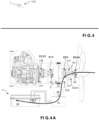
Figure 4 est une vue schématique d'un aéronef conformément à un mode de réalisation de l'invention, au cours d'une descente de l'aéronef ; - la
Figure 4A est une vue schématique d'un groupe motopropulseur d'un aéronef conformément à un mode de réalisation de l'invention, en mode récupération d'énergie électrique ; - la
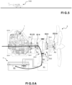
Figure 5 est une vue schématique d'un aéronef conformément à un mode de réalisation de l'invention, l'aéronef étant au sol ; - la
Figure 5A est une vue schématique d'un groupe motopropulseur d'un aéronef conformément à un mode de réalisation de l'invention, en mode recharge via son moteur thermique alors que l'aéronef est au sol ; - la
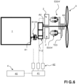
Figure 6 est une vue schématique d'une variante non revendiquée de groupe motopropulseur. - Le concept de l'invention est décrit plus complètement ci-après avec référence aux dessins joints, sur lesquels des modes de réalisation du concept de l'invention sont montrés. Sur les dessins, la taille et les tailles relatives des éléments peuvent être exagérées à des fins de clarté. Des numéros similaires font référence à des éléments similaires sur tous les dessins. Cependant, ce concept de l'invention peut être mis en oeuvre sous de nombreuses formes différentes et ne devrait pas être interprété comme étant limité aux modes de réalisation exposés ici, mais par les revendications. Au lieu de cela, ces modes de réalisation sont proposés de sorte que cette description soit complète, et communiquent l'étendue du concept de l'invention aux hommes du métier. Les modes de réalisation qui suivent sont examinés, par souci de simplification, en relation avec la terminologie et la structure d'un aéronef. Comme expliqué ci-après, l'engin peut aussi être un engin nautique.
- Une référence dans toute la spécification à « un mode de réalisation » signifie qu'une fonctionnalité, une structure, ou une caractéristique particulière décrite en relation avec un mode de réalisation est incluse dans au moins un mode de réalisation de la présente invention. Ainsi, l'apparition de l'expression « dans un mode de réalisation » à divers emplacements dans toute la spécification ne fait pas nécessairement référence au même mode de réalisation. En outre, les fonctionnalités, les structures, ou les caractéristiques particulières peuvent être combinées dans un ou plusieurs modes de réalisation.
- A la
figure 1 , on a illustré un engin qui est un aéronef 100 à hélice. L'aéronef est par exemple un avion, un drone ou un hélicoptère. - L'aéronef 100 comporte un groupe motopropulseur, encore appelé module de puissance, qui comprend un carter 190 et un système de propulsion à hélice, une motorisation thermique et une motorisation électrique. Comme visibles aux
figures 1 à 5 et comme expliqué ci-après, le carte 190 loge la motorisation thermique, le rotor 202 du moteur électrique 2, le stator 201 pour être formé par une partie du carter 190. - Le groupe motopropulseur peut également être appliqué à une propulsion nautique, de sorte que l'engin peut être un engin nautique. Le système de propulsion à hélice comprend une hélice 3 et un arbre A3 d'hélice auquel est fixé l'hélice 3.
- A titre d'exemple, le moteur thermique et/ou le moteur électrique peuvent permettre d'entraîner un ou plusieurs autres systèmes de propulsion à hélice supplémentaires 3' comme schématisé sur la
figure 1 . Ce type de configuration peut être appelé « propulsion distribuée ». - La motorisation thermique comprend un moteur thermique 1 qui présente un arbre A1 de sortie, entrainable en rotation par le moteur thermique. Le moteur thermique peut par exemple tourner à une vitesse de l'ordre de 6000 tours/minute.
- Selon un mode de réalisation, le groupe motopropulseur comprend un amortisseur de couple AM1 permettant de corriger/lisser les acyclismes du moteur thermique.
- La motorisation électrique comprend un moteur électrique 2. Le moteur électrique 2 peut tourner par exemple à une vitesse de l'ordre de 6000 tours/minute. La motorisation électrique comporte aussi un système d'alimentation 4 électrique qui comprend une batterie 40 permettant d'alimenter le moteur électrique 2.
- Un système de réduction, par exemple à train épicycloïdal tel que présenté ci-après, permet que l'hélice soit entraînée à une vitesse plus faible, par exemple de l'ordre de 2000 tours/minute.
- Le système d'alimentation 4 électrique comporte aussi un système de gestion électrique 41, 42 qui comprend un boîtier haute-tension 41 qui permet d'ouvrir ou de fermer le circuit d'alimentation entre la batterie 40 et le moteur électrique 2. Le système d'alimentation 4 électrique comporte aussi un contrôleur 42 qui permet de traiter le courant fourni par la batterie 40 ou produit par le moteur électrique 2 lorsqu'il fonctionne en génératrice.
- A titre d'exemple, le contrôleur 42 peut ainsi transformer le courant continu issu de la batterie 40 en courant alternatif, par exemple en le hachant pour alimenter le moteur électrique 2, et inversement pour transformer le courant alternatif produit par le moteur électrique 2 en courant continu pour permettre la recharge de la batterie 40, lorsque le moteur électrique 2 fonctionne en génératrice, en particulier lorsque, comme expliqué ci-après, le rotor du moteur électrique 2 est entraîné par le moteur thermique 1 ou l'hélice 3.
- Le groupe motopropulseur comprend aussi un système d'embrayages configuré pour pouvoir présenter plusieurs configurations comme détaillé ci-après. Comme expliqué ci-après, l'agencement de la motorisation électrique, de la motorisation thermique et du système de propulsion à hélice permet, en combinaison avec le système d'embrayages, de sélectivement :
- entraîner le système de propulsion à hélice 3 pour la propulsion de l'aéronef à l'aide du moteur thermique 1 seul ;
- entraîner le système de propulsion à hélice 3 dans le sens de la propulsion de l'aéronef à l'aide du moteur thermique 1 seul et d'entraîner le moteur électrique 2 pour le rechargement de la batterie et éventuellement d'une ou plusieurs autres batteries, à l'aide du moteur thermique 1 ;
- entraîner le système de propulsion à hélice 3 pour la propulsion de l'aéronef à l'aide de la motorisation électrique 2 seule ;
- entraîner le système de propulsion à hélice 3 à l'aide du mouvement de rotation de l'arbre de sortie du moteur thermique 1 transmis à l'arbre d'hélice et du mouvement de rotation du moteur électrique 2 transmis également à l'arbre d'hélice (ou hélice 3). Autrement dit, dans ce cas la rotation de l'hélice résulte de la transmission à l'arbre d'hélice A3 (ou hélice 3) du mouvement de rotation combiné du moteur thermique et du moteur électrique.
- Selon un mode de réalisation particulier, le système d'embrayages du groupe motopropulseur présente une configuration permettant d'entraîner le moteur électrique 2 pour le rechargement de la batterie 40, lorsque l'hélice 3 est entraînée par effet éolien (ou hydrolien).
- Le système d'embrayages peut comprendre des embrayages de type à friction ou à crabot.
- Le groupe motopropulseur comprend un arbre intermédiaire A2. Comme visible aux figures, l'arbre intermédiaire A2 est interposé entre l'arbre de sortie 1 et l'arbre d'hélice A3. Par ailleurs, l'arbre intermédiaire A2 est logé dans le rotor 202.
- Dans le mode de réalisation des
figures 1 à 5 , l'arbre A2 est solidarisable (couplable) en rotation de l'arbre d'hélice A3 par l'intermédiaire de l'embrayage E23. Dans l'exemple alternatif illustré à lafigure 6 et présenté ci-après, l'arbre A2 correspond à une portion dudit arbre d'hélice A3. - Le système d'embrayages comprend un embrayage E123 qui, à l'état fermé, transmet la rotation du moteur thermique 1 à l'arbre intermédiaire A2. A l'état ouvert de l'embrayage E123, la rotation de la motorisation thermique 1 n'est plus transmise à l'arbre intermédiaire A2. L'embrayage E123 est situé entre l'arbre A1 de sortie du moteur thermique et l'arbre intermédiaire A2.
- Le système d'embrayages comprend aussi un embrayage E324 qui, à l'état fermé, transmet la rotation du moteur électrique 2, en particulier du rotor 202, à l'hélice 3. A l'état ouvert de l'embrayage E324, le rotor 202 n'est plus couplé en rotation à l'hélice 3, ou arbre d'hélice A3 (en particulier lorsque l'embrayage E14 et/ou E23 est ouvert).
- Le système d'embrayages comprend l'embrayage E23 qui, à l'état fermé, permet de transmettre la rotation de l'arbre intermédiaire A2 à l'arbre d'hélice A3, de préférence avec un système de réduction.
- L'embrayage E23 permet de transmettre à l'arbre d'hélice A3 la rotation de l'arbre intermédiaire A2 qui provient de la rotation de l'arbre de sortie A1, à l'état fermé de l'embrayage E123, et/ou qui provient de la rotation du rotor 202 à l'état fermé de l'embrayage E14.
- L'ouverture des embrayages permet d'interrompre la transmission de mouvement correspondante.
- Dans l'exemple illustré aux
figures 1 à 5 , le système d'embrayages comprend un embrayage E14 dont une première partie est, à l'état fermé du premier embrayage E123, solidaire en rotation de l'arbre A1 de sortie du moteur thermique 1. Ladite première partie de l'embrayage E14 est montée solidaire en rotation d'une partie de l'arbre intermédiaire A2. Une deuxième partie de l'embrayage E14 est montée solidaire en rotation du rotor 202 du moteur électrique 2. - Dans l'exemple illustré aux
figures 1 à 5 , l'embrayage E324 présente une partie qui est couplée (en rotation) au rotor 202 du moteur électrique 2 par l'intermédiaire d'un système de transmission mécanique à engrenages S3, S223, C213, et dont l'autre partie est solidaire en rotation de l'hélice 3 (ou arbre d'hélice). En particulier, ladite autre partie est montée solidaire de la base du nez de l'hélice 3, encore appelé plateau d'hélice. L'embrayage E324 permet ainsi de transmettre la rotation du rotor 202 du moteur électrique 2 à l'hélice 3 (ou encore à l'arbre d'hélice A3 qui est solidaire de l'hélice). - En position fermée, l'embrayage E324 permet que le moteur électrique 2 soit entraîné par l'hélice 3 lorsque celle-ci est entraînée par le flux extérieur auquel elle est soumise (effet éolien ou hydrolien).
- Le système de transmission mécanique S3, S223, C213 est un système de transmission par engrènement. Le système de transmission est de préférence de type train épicycloïdal. Le train épicycloïdal comprend un arbre intérieur S3, appelé soleil, correspondant à une partie du rotor 202 du moteur électrique 2, et une couronne C213 portée par l'intérieur du corps creux du stator 201 (présenté ci-après) et un satellite S223 interposé entre le soleil S3 et la couronne C213. Le satellite S223 est solidaire d'un porte-satellite qui est coaxial avec l'arbre d'hélice A3. L'extrémité du porte-satellite opposée au satellite S223 est monté solidaire en rotation d'une partie de l'embrayage E324.
- L'embrayage E23 comprend une partie couplée (en rotation) à l'arbre intermédiaire A2 par le système transmission mécanique à engrenages S2, S23, C223 et une autre partie solidaire en rotation de l'arbre d'hélice A3.
- Dans l'exemple illustré aux
figures 1 à 5 , le système de transmission mécanique S2, S23, C223 est un système de transmission par engrènement. Le système de transmission est de préférence de type train épicycloïdal. Le train épicycloïdal comprend un arbre intérieur S2, appelé soleil, correspondant à une partie de l'arbre intermédiaire 2 et une couronne C223 portée par l'intérieur du corps creux du rotor. Un satellite S23 est interposé entre le soleil S2 et la couronne C223. Le satellite S23 est solidaire d'un porte-satellite qui est coaxial avec l'arbre intermédiaire A2 et l'arbre d'hélice A3. L'extrémité du porte-satellite opposée au satellite S23 est solidaire en rotation d'une partie de l'embrayage E23. - Comme illustré aux
figures 1 à 5 , le moteur électrique 2 comprend un stator 201 et un rotor 202. Le stator 201 a un corps creux muni d'un bobinage 21 sur sa face interne. Dans l'exemple illustré auxfigures 1 à 5 , le stator 201 est une partie du carter 190. - Le rotor 202 a un corps rotatif autour de l'axe (longitudinal) de l'arbre intermédiaire A2 et à l'intérieur du stator 201. Selon l'état de configuration du système d'embrayage le rotor peut tourner autour de l'arbre intermédiaire A2, relativement audit arbre intermédiaire, ou tourner avec ledit arbre intermédiaire A2 autour dudit axe (longitudinal) de l'arbre intermédiaire A2. Avantageusement, le rotor 202 est muni d'aimants 22 sur sa face périphérique externe.
- L'entraînement de l'arbre intermédiaire A2 en rotation par l'arbre A1 de sortie du moteur 1 ou par la rotation du rotor 202 du moteur électrique 2, permet d'entraîner en rotation le satellite S23 et ainsi le porte-satellite couplé à l'embrayage E23. La fermeture de l'embrayage E23 permet de transmettre cette rotation à l'arbre d'hélice A3 pour l'entraînement en rotation de l'hélice 3.
- Ainsi, la rotation de l'arbre intermédiaire A2 peut être transmise à l'arbre d'hélice A3, et donc à l'hélice 3, par fermeture de l'embrayage E23.
- Par ailleurs, la fermeture de l'embrayage E324 permet de transmettre le mouvement de rotation entre le rotor 202 du moteur électrique 2 et l'hélice 3.
- Selon un mode de réalisation, le système d'embrayages E123, E14, E23, E324 est aussi configuré pour présenter une configuration selon laquelle l'hélice 3, mise en rotation par effet éolien ou hydrolien, transmet son mouvement de rotation au moteur électrique 2 pour générer un courant électrique permettant de recharger la batterie 40.
- Selon un mode de réalisation, l'un des embrayages E14, E324 est ouvert, tandis que l'autre embrayage E324, E14 est fermé.
- On peut prévoir qu'une ou chacune des parties d'un embrayage montée solidaire en rotation d'un arbre soit monté coulissant, par exemple à l'aide de cannelures, sur ledit arbre pour passer d'une position de fermeture à une position d'ouverture et inversement.
- Le groupe motopropulseur présenté ci-avant permet de mettre en oeuvre différents procédés de pilotage de l'aéronef en adaptant la configuration des embrayages.
- Dans l'exemple illustré aux
figures 2A ,2B ,2C ,3A ,4A ,5A les embrayages sont représentés par simplification en position ouverte. Pour autant, la description ci-après précise la configuration réelle, ouverte ou fermée, de chacun desdits embrayages selon le procédé de pilotage mis en oeuvre. Par ailleurs, des flèches ont été ajoutées (distinctes des flèches de référence) pour symboliser la chaîne de transmission de mouvement qui est active et le cas échéant le courant électrique délivré ou reçu par le système d'alimentation électrique. - Pour un usage optimal de l'aéronef lors d'une phase de décollage et/ou de montée, le groupe motopropulseur permet une propulsion électrique de l'aéronef.
- Dans l'exemple illustré aux
figures 2 et 2A , les embrayages sont amenés dans la configuration suivante. L'embrayage E123 est ouvert pour libérer le moteur thermique 1 par rapport à l'hélice 3. L'embrayage E14 et l'embrayage E23 sont de préférence ouverts. L'embrayage E324 est fermé pour transmettre le mouvement du moteur électrique 2 à l'hélice 3. La flèche montre que le mouvement de rotation du rotor 202 du moteur électrique 2, alimenté électriquement par la batterie 40, est transmis à l'hélice 3 par l'embrayage E324. - Dans l'hypothèse d'une panne se produisant sur la chaîne de transmission électrique, le groupe motopropulseur permet d'utiliser la propulsion thermique sans utilisation de la motorisation électrique.
- Ainsi, dans l'exemple illustré à la
Figure 2B , les embrayages peuvent être amenés dans une configuration selon laquelle l'embrayage E123 et l'embrayage E23 sont fermés pour transmettre le mouvement du moteur thermique 1 à l'hélice 3. Le mouvement du moteur thermique 1 est transmis à l'hélice 3 par les arbres A1, A2 et A3. Selon un aspect particulier illustré pour le mode de réalisation de lafigure 2B , l'embrayage E14 et l'embrayage E324 sont ouverts pour éviter que le rotor 202 du moteur électrique 2 ne tourne. La flèche montre que le moteur thermique 1 transmet son mouvement de rotation à l'hélice 3 via les embrayages E123 et E23. - Une panne peut résulter par exemple d'une surchauffe de la batterie, d'un dysfonctionnement d'un composant de la chaîne de transmission électrique. Il en résulte que le rotor du moteur électrique ne tourne plus.
- Comme expliqué ci-dessus, en cas de panne sur la chaîne de transmission électrique, on peut prévoir par sécurité d'ouvrir E324 et de préférence E14 pour réduire le risque de problème électrique supplémentaire qui résulterait de la rotation dans un sens ou dans l'autre du rotor 202.
- La panne peut être détectée en fonction des critères suivants qui peuvent être pris ou non dans toute combinaison techniquement possible :
- diminution de puissance électrique par rapport à une valeur seuil,
- diminution de vitesse rotation,
- diminution de la pente de la trajectoire,
- diminution de la vitesse d'avance de l'aéronef,
- augmentation inusuelle de l'ampérage
- Lorsqu'une panne électrique est détectée alors que seule la propulsion électrique était utilisée, on peut ainsi prévoir de passer en mode propulsion thermique pour palier la panne sur la chaîne de transmission électrique.
- Une telle configuration des embrayages qui permet un entraînement de l'hélice par le moteur thermique seul, c'est-à-dire sans apport du moteur électrique, peut aussi être utilisée lors d'un décollage normal pour conserver la charge de la batterie électrique ou lorsque celle-ci est déchargée.
- Une telle configuration des embrayages peut aussi être utilisée lors d'un vol en palier de l'aéronef lorsque la batterie est considérée comme suffisamment chargée et que l'on souhaite conserver sa charge.
- Le groupe motopropulseur permet en outre de combiner le mouvement de rotation fourni par le moteur thermique et le mouvement de rotation fourni par le moteur électrique pour entraîner l'hélice.
- Ainsi, par exemple lorsque la piste de décollage est courte, afin de bénéficier d'un mode dit superpuissance, c'est-à-dire pour une propulsion par usage cumulé du moteur thermique 1 et du moteur électrique 2, les embrayages peuvent être amenés dans la configuration suivante illustrée à la
Figure 2C . L'embrayage E123 est fermé, l'embrayage E14 est ouvert, l'embrayage E23 est fermé pour transmettre le mouvement du moteur thermique 1 à l'hélice 3 et l'embrayage E324 est fermé pour transmettre le mouvement du moteur électrique 2 à l'hélice 3. Les flèches montrent que le moteur thermique transmet son mouvement de rotation à l'hélice via les embrayages E123 et E23, tandis que le mouvement de rotation du rotor 202 du moteur électrique 2 alimenté en courant par la batterie 40 est transmis à l'hélice par l'embrayage E324. - Le groupe motopropulseur permet en outre de recharger la batterie 40 à l'aide du moteur thermique 1 tout en conservant un entraînement en rotation de l'hélice 3. Ainsi, par exemple pour une recharge en vol de l'aéronef comme illustré aux
figures 3 et 3A , les embrayages peuvent être amenés dans la configuration suivante. L'embrayage E324 est ouvert. L'embrayage E123, l'embrayage E14 et l'embrayage E23 sont fermés. Ainsi, comme l'illustre la flèche, le moteur thermique 1 entraine l'arbre intermédiaire A2, ce qui fait tourner le rotor 202 muni des aimants 22 en regard du bobinage 21 du stator 201 et génère ainsi une courant dans le bobinage 21, tout en entraînant l'arbre d'hélice A3. Le système de gestion électrique 41, 42 contrôle le courant produit par la rotation du rotor 202 afin de recharger la batterie 40. - Un tel mode de fonctionnement du groupe motopropulseur permet d'utiliser le surplus de puissance du moteur thermique 1 pour recharger la batterie 40 en vol, notamment lorsque la batterie a été utilisée pour la propulsion électrique en phase de roulage, décollage et/ou de montée.
- Le groupe motopropulseur permet une récupération d'énergie par effet éolien ou hydrolien. Ainsi, notamment lors d'une descente de l'aéronef en laissant l'hélice 3 tourner sous l'effet du flux d'air dans lequel elle se situe, comme illustré aux
Figures 4 et 4A , les embrayages peuvent être amenés dans la configuration suivante. L'embrayage E123 et l'embrayage E14 sont ouverts pour découpler l'hélice 3 par rapport au moteur thermique 1 et découpler le rotor 202 par rapport au moteur thermique 1. De préférence, l'embrayage E23 est ouvert. L'embrayage E324 est fermé. La flèche montre ainsi que le mouvement de l'hélice 3 est transmis au rotor 202 du moteur électrique 2 via le satellite S223 et le soleil S3 et que le courant ainsi généré est utilisé pour recharger la batterie 40. - Le groupe motopropulseur permet de recharger la batterie 40 à l'aide du moteur thermique 1 sans entraîner l'hélice 3. Ainsi, par exemple pour une recharge au sol de l'aéronef et comme illustré aux
Figures 5 et 5A , les embrayages peuvent être amenés dans la configuration suivante. L'embrayage E324 et l'embrayage E23 sont ouverts. L'embrayage E123 et l'embrayage E14 sont fermés. Ainsi comme le montre la flèche de lafigure 5A , le moteur thermique 1 entraine l'arbre intermédiaire A2 pour faire tourner le rotor 202 muni des aimants 22 en regard du bobinage 21 du stator 201 afin de générer une courant que le système de gestion électrique 41, 42 contrôle pour recharger la batterie 40. - Selon un mode de réalisation particulier, l'aéronef comprenant des roues munies d'une motorisation électrique connectée à la batterie 40 d'alimentation de l'aéronef par l'intermédiaire d'un système 41, 42 de gestion électrique. Dans ce cas le groupe motopropulseur permet d'alimenter la motorisation électrique des roues par la batterie 40 électrique.
- Le système de gestion de la motorisation électrique des roues peut être celui qui sert également à la gestion de l'alimentation du moteur électrique de l'aéronef ou être un système de gestion distinct, interposé entre la batterie et la motorisation électrique des roues.
- Le moteur thermique 1 peut être éteint ou peut tourner au ralenti en attendant d'être utilisé. En particulier dans le cas où le moteur thermique est allumé, chacun des embrayages E23 et E324 est débrayé afin de ne pas entraîner l'hélice.
- Le fait de ne pas entraîner l'hélice permet d'augmenter la sécurité du matériel et des personnes autour de l'avion en phase de roulage tout en évitant de consommer inutilement de l'énergie de la batterie par mise en rotation de l'hélice.
- Dans l'exemple de la
figure 6 , le groupe motopropulseur comprend un embrayage E123, par exemple à friction, entre ledit moteur thermique 1 et l'arbre intermédiaire A2. - Dans cet exemple de la
figure 6 , l'arbre d'hélice A3 est solidaire de l'arbre intermédiaire A2. - Une partie de l'embrayage E123 est couplée en rotation à l'arbre de sortie A1du moteur thermique 1 et l'autre partie de l'embrayage E123 est couplée en rotation à une partie de l'arbre intermédiaire A2.
- L'arbre intermédiaire A2 est en deux parties décalées axialement l'une par rapport à l'autre. Les deux parties de l'arbre intermédiaire A2 sont raccordées entre elles par un dispositif de transmission T12 à poulies et courroie.
- La motorisation électrique peut comprendre un ou plusieurs moteurs électriques 2 décalés axialement par rapport à l'arbre d'hélice A3. On pourrait également prévoir un décalage "radial" avec un système d'engrenages à renvoi d'angle, et sur chaque arbre de sortie de moteur électrique un système de crabotage ou d'embrayage.
- Chaque moteur électrique 2 est raccordé au système d'alimentation 4 électrique. En particulier, il est prévu un contrôleur 42 par moteur électrique 2.
- L'arbre de sortie de chaque moteur électrique 2 est solidaire en rotation d'une partie d'un embrayage E324', de préférence de type crabot. L'autre partie de l'embrayage E324' est solidaire en rotation d'un système de transmission T23, par exemple à poulies et courroie, agencé pour transmettre le mouvement de rotation de la motorisation électrique à l'arbre d'hélice A3.
- Chaque embrayage E324' permet de découpler le moteur électrique 2 associé par rapport au système de transmission T23, notamment en cas de défaillance dudit ou de chacun desdits moteurs électriques.
- Ainsi, dans cet exemple illustré à la
figure 6 , chaque moteur électrique 2 est doté d'un système indépendant d'embrayage E324' de type à friction ou par crabotage, qui peut être assimilé fonctionnellement à l'embrayage E324 du mode de réalisation desfigures 1 à 5 . - Seuls deux moteurs électriques sont schématisés à la
figure 6 , mais un troisième moteur électrique est néanmoins présent et relié au système de transmission T23, de manière similaire aux autre moteurs électrique, par un embrayage à friction ou à crabots, par exemple du type de l'embrayage E324'. La motorisation électrique présente de préférence trois moteurs électriques ou plus. - Dans le mode de réalisation illustré aux
figures 1 à 5 , les arbres du groupe motopropulseur sont coaxiaux et la transmission de mouvement d'un arbre s'effectue à l'aide d'embrayages également coaxiaux. Selon la variante non revendiquée de lafigure 6 , les arbres A1 et A3 sont décalés axialement. - On comprend ainsi que l'arbre d'hélice A3 peut être entraîné par la motorisation électrique à l'état fermé du ou de chaque 'embrayage E324', et/ou par le moteur thermique à l'état fermé de l'embrayage E123.
- On peut prévoir que le système d'embrayages soit commandé pour passer d'une configuration à une autre par un dispositif de commande manuel ou automatique. En particulier on peut prévoir qu'une unité de pilotage, telle qu'un calculateur, permette de piloter un système d'actionnement des embrayages pour commander le passage d'une configuration à un autre. L'unité de pilotage peut se présenter sous la forme d'un processeur et d'une mémoire de données dans laquelle sont stockées des instructions informatiques exécutables par ledit processeur, ou encore sous la forme d'un microcontrôleur.
- Autrement dit, les fonctions et étapes décrites peuvent être mise en oeuvre à l'aide de programme informatique ou via des composants matériels (p. ex. des réseaux de portes programmables). En particulier, les fonctions et étapes opérées par l'unité de pilotage peuvent être réalisées par des jeux d'instructions ou modules informatiques implémentés dans un processeur ou contrôleur ou être réalisées par des composants électroniques dédiés ou des composants de type FPGA ou ASIC. Il est aussi possible de combiner des parties informatiques et des parties électroniques.
- Dans le cas où l'aéronef est un avion muni de roues, il est également possible de prévoir qu'une ou plusieurs roues soit munies d'un moteur électrique, par exemple incorporé dans le moyeu. Le moteur électrique de chaque roue peut être raccordé au système de gestion électrique de l'aéronef. Ainsi pour la phase de roulage, le ou les moteurs électriques des roues peuvent être alimentés par la batterie 40 à l'aide du système d'alimentation 4 électrique.
- L'aéronef peut comprendre plusieurs systèmes de propulsion à hélice auxiliaires qui peuvent être commandés de manière indépendante les uns des autres.
- Selon un exemple, l'aéronef peut comprendre deux moteurs à hélice auxiliaires (de préférence latéraux) et entre les deux moteurs à hélice, le système de propulsion à hélice du groupe motopropulseur selon l'invention. Ces motorisations auxiliaires et le groupe motopropulseur peuvent être indifféremment de type tractif ou propulsif.
- On peut prévoir que la ou chaque hélice est à pas variable et qu'elle peut être mise en configuration dite drapeau pour réduire la trainée en cas de non utilisation.
- L'invention n'est pas limitée aux modes de réalisation illustrés dans les dessins.
- De plus, le terme « comprenant » n'exclut pas d'autres éléments ou étapes. En outre, des caractéristiques ou étapes qui ont été décrites en référence à l'un des modes de réalisation exposés ci-dessus peuvent également être utilisées en combinaison avec d'autres caractéristiques ou étapes d'autres modes de réalisation exposés ci-dessus.
le groupe motopropulseur comprend aussi un système d'embrayages configuré pour permettre, sélectivement :
Claims (15)
- Engin (100), tel qu'un aéronef, muni d'un groupe motopropulseur qui comprend :- une motorisation thermique comprenant un moteur thermique (1) et un arbre (A1), appelé arbre de sortie du moteur thermique, entrainable en rotation par le moteur thermique ;- une motorisation électrique comprenant un moteur électrique (2) ;- un système d'alimentation (4) électrique comprenant une batterie (40) permettant d'alimenter le moteur électrique (2) ;- un système de propulsion à hélice comprenant une hélice (3) et un arbre (A3), appelé arbre d'hélice, auquel est couplé l'hélice (3) ;le groupe motopropulseur comprenant aussi un système d'embrayages (E123, E14, E23, E324) configuré pour permettre, sélectivement :- d'entraîner l'hélice (3) à l'aide du moteur thermique (1) sans transmission de rotation du moteur électrique (2) à l'hélice (3) ;- d'entraîner l'hélice (3) à l'aide du moteur électrique (2) sans transmission de rotation du moteur thermique (1) à l'hélice (3) ;- d'entraîner l'hélice (3) par transmission combinée du mouvement de rotation du moteur thermique (1) à l'hélice (3), et du mouvement de rotation du moteur électrique (2) à l'hélice (3) ;le groupe motopropulseur comprenant un arbre (A2), appelé arbre intermédiaire, solidaire de ou couplable en rotation à l'arbre d'hélice (A3),et le système d'embrayages comprenant :- un premier embrayage (E123) configuré pour, à l'état fermé, transmettre la rotation du moteur thermique (1) à l'arbre intermédiaire (A2), et- un deuxième embrayage (E23) configuré pour, à l'état fermé, transmettre la rotation de l'arbre intermédiaire (A2) à l'arbre d'hélice (A3) et un troisième embrayage (E324) configuré pour, à l'état fermé, transmettre la rotation du moteur électrique (2) à l'arbre d'hélice (A3) ;le moteur électrique (2) comprenant un stator (201) et un rotor (202), le rotor présentant un corps creux et étant monté rotatif autour de l'arbre intermédiaire (A2) et à l'intérieur du stator (201), le rotor (202) et l'arbre intermédiaire (A2) étant coaxiaux.
- Engin (100) selon la revendication 1, dans lequel chaque arbre (A1, A2) qui forme partie de la chaîne de transmission de mouvement à l'hélice (3) est coaxial avec l'arbre d'hélice (A3).
- Engin (100) selon la revendication 1 ou 2, dans lequel le stator (201) se présente sous la forme d'un corps creux et muni d'un bobinage (21), et le rotor (202) est muni d'aimants (22).
- Engin (100) selon l'une quelconque des revendication 1 à 3, dans lequel le groupe motopropulseur comprend aussi un système de transmission mécanique (S2, S23, C223) de type train épicycloïdal, qui comprend :- un arbre intérieur (S2), appelé soleil, correspondant à une partie de l'arbre intermédiaire (2) et une couronne (C223) portée par l'intérieur du corps creux du rotor ;- un satellite (S23) interposé entre le soleil (S2) et la couronne (C223), et un porte-satellite dont l'extrémité opposée au satellite (S23) est solidaire en rotation d'une partie du deuxième embrayage (E23), le deuxième embrayage (E23) comprenant une autre partie solidaire en rotation de l'arbre d'hélice (A3).
- Engin (100) selon l'une quelconque des revendications 1 à 4, dans lequel le système d'embrayages comprend un quatrième embrayage (E14) configuré pour, à l'état fermé, transmettre la rotation du moteur thermique (1) au moteur électrique (2) pour le faire fonctionner en génératrice.
- Engin (100) selon la revendication 5, dans lequel le quatrième embrayage (E14) comprend une partie qui est, à l'état fermé du premier embrayage (E123), solidaire en rotation de l'arbre (A1) de sortie du moteur thermique (1), et une autre partie qui est montée solidaire en rotation du rotor (202) du moteur électrique (2).
- Engin (100) selon l'une quelconque des revendications 1 à 6, dans lequel le troisième embrayage (E324) comprend une partie solidaire en rotation du rotor (202) du moteur électrique (2) par l'intermédiaire d'un système de transmission mécanique (S3, S223, C213), et une partie solidaire en rotation de l'hélice (3).
- Engin (100) selon l'une quelconque des revendications 1 à 6, dans lequel le système d'alimentation (4) électrique comporte aussi un système de gestion électrique (41, 42) qui comprend :- un boîtier haute-tension (41) qui permet d'ouvrir ou de fermer le circuit d'alimentation entre la batterie (40) et le moteur électrique (2) ;- un contrôleur (42) qui permet de traiter le courant fourni par la batterie (40) ou produit par le moteur électrique (2) lorsqu'il fonctionne en génératrice.
- Procédé de pilotage d'un engin (100) conforme à l'une quelconque des revendications 5 à 6, caractérisé en ce que ledit procédé de pilotage comporte une étape de propulsion électrique, notamment lors d'une phase de décollage et/ou de montée, selon laquelle les embrayages sont amenés dans la configuration suivante :- le premier embrayage (E123) est ouvert pour libérer le moteur thermique (1) par rapport à l'hélice (3) ;- le quatrième embrayage (E14) et le deuxième embrayage (E23) sont de préférence ouverts ;- le troisième embrayage (E324) est fermé pour transmettre le mouvement du moteur électrique (2) à l'hélice (3).
- Procédé de pilotage d'un engin (100) conforme à l'une quelconque des revendications 1 à 8, dans lequel ledit procédé de pilotage comporte une étape de propulsion thermique sans utilisation de la motorisation électrique, par exemple lorsqu'une panne se produit sur la chaîne de transmission électrique, selon laquelle les embrayages sont amenés dans la configuration suivante :- le premier embrayage (E123) est fermé ;- le deuxième embrayage (E23) est fermé pour transmettre le mouvement du moteur thermique (1) à l'hélice (3).
- Procédé de pilotage d'un engin (100) conforme à l'une quelconque des revendications 5 à 6, dans lequel ledit procédé de pilotage comporte une étape de propulsion par usage cumulé du moteur thermique (1) et du moteur électrique (2), selon laquelle les embrayages sont amenés dans la configuration suivante :- le premier embrayage (E123) est fermé ;- le deuxième embrayage (E23) est fermé pour transmettre le mouvement du moteur thermique (1) à l'hélice (3) ;- le troisième embrayage (E324) est fermé pour transmettre le mouvement du moteur électrique (2) à l'hélice (3) ;- le quatrième embrayage (E14)est ouvert.
- Procédé de pilotage d'un engin (100) conforme à la revendication 5 ou 6, dans lequel ledit procédé de pilotage comporte une étape de recharge de la batterie (40) à l'aide du moteur thermique (1) tout en conservant un entraînement en rotation de l'hélice (3), par exemple pour une recharge en vol de l'engin, selon laquelle les embrayages sont amenés dans la configuration suivante :le premier embrayage (E123), le quatrième embrayage (E14) et le deuxième embrayage (E23) sont fermés, de sorte que le moteur thermique (1) entraine l'arbre intermédiaire (A2) pour faire tourner le rotor (202) en regard du stator (201) afin de générer un courant, tout en entraînant l'arbre d'hélice (A3) ;et en ce que le système de gestion électrique (41, 42) contrôle le courant produit par le moteur électrique (2) fonctionnant en génératrice pour recharger la batterie (40).
- Procédé de pilotage d'un engin (100) conforme à la revendication 5 ou 6, dans lequel ledit procédé de pilotage comporte une étape de récupération d'énergie par effet éolien ou hydrolien, selon laquelle les embrayages sont amenés dans la configuration suivante :- au moins l'un parmi le premier embrayage (E123) et le quatrième embrayage (E14) est ouvert pour découpler l'hélice (3) par rapport au moteur thermique (1) ou découpler le rotor (202) par rapport au moteur thermique (1) ;- de préférence, le deuxième embrayage (E23) est ouvert ;- le troisième embrayage (E324) est fermé pour transmettre le mouvement de l'hélice (3) au rotor (202) du moteur électrique (2).
- Procédé de pilotage d'un engin (100) conforme à la revendication 5 ou 6, dans lequel ledit procédé de pilotage comporte une étape de recharge de la batterie (40) à l'aide du moteur thermique (1) sans entraîner l'hélice (3), selon laquelle les embrayages sont amenés dans la configuration suivante :- ouverture du troisième embrayage (E324) et du deuxième embrayage (E23),- fermeture du premier embrayage (E123) et du quatrième embrayage (E14), de sorte que le moteur thermique (1) entraine l'arbre intermédiaire (A2) pour faire tourner le rotor (202) afin de générer un courant,et en ce que le système de gestion électrique (41, 42) contrôle le courant produit par le moteur électrique (2) fonctionnant en génératrice pour recharger la batterie (40).
- Procédé de pilotage selon l'une quelconque des revendications 9 à 14, d'un engin (100) conforme à l'une quelconque des revendications 1 à 8, dans lequel, l'engin comprenant des roues munies d'une motorisation électrique connectée à la batterie (40) d'alimentation de l'engin par l'intermédiaire d'un système (41, 42) de gestion électrique, le procédé comprend l'alimentation de la motorisation électrique des roues par la batterie (40) électrique.
Applications Claiming Priority (2)
| Application Number | Priority Date | Filing Date | Title |
|---|---|---|---|
| FR1801092A FR3087421B1 (fr) | 2018-10-17 | 2018-10-17 | Engin comprenant un groupe motopropulseur hybride et procede de pilotage correspondant |
| PCT/FR2019/052456 WO2020079369A1 (fr) | 2018-10-17 | 2019-10-16 | Engin comprenant un groupe motopropulseur hybride et procede de pilotage correspondant |
Publications (4)
| Publication Number | Publication Date |
|---|---|
| EP3867152A1 EP3867152A1 (fr) | 2021-08-25 |
| EP3867152B1 true EP3867152B1 (fr) | 2024-12-25 |
| EP3867152C0 EP3867152C0 (fr) | 2024-12-25 |
| EP3867152B8 EP3867152B8 (fr) | 2025-02-19 |
Family
ID=65243647
Family Applications (1)
| Application Number | Title | Priority Date | Filing Date |
|---|---|---|---|
| EP19808629.0A Active EP3867152B8 (fr) | 2018-10-17 | 2019-10-16 | Engin comprenant un groupe motopropulseur hybride et procédé de pilotage correspondant |
Country Status (15)
| Country | Link |
|---|---|
| US (1) | US12030654B2 (fr) |
| EP (1) | EP3867152B8 (fr) |
| JP (1) | JP7495928B2 (fr) |
| KR (1) | KR102658150B1 (fr) |
| CN (1) | CN112805218B (fr) |
| AU (1) | AU2019361306B2 (fr) |
| CA (1) | CA3131899A1 (fr) |
| ES (1) | ES3013789T3 (fr) |
| FR (1) | FR3087421B1 (fr) |
| IL (1) | IL281907B2 (fr) |
| MX (1) | MX2021004414A (fr) |
| PL (1) | PL3867152T3 (fr) |
| RU (1) | RU2761151C1 (fr) |
| SG (1) | SG11202103308SA (fr) |
| WO (1) | WO2020079369A1 (fr) |
Families Citing this family (25)
| Publication number | Priority date | Publication date | Assignee | Title |
|---|---|---|---|---|
| WO2020137103A1 (fr) * | 2018-12-27 | 2020-07-02 | 本田技研工業株式会社 | Objet volant |
| WO2020137104A1 (fr) * | 2018-12-27 | 2020-07-02 | 本田技研工業株式会社 | Objet volant |
| US11732639B2 (en) * | 2019-03-01 | 2023-08-22 | Pratt & Whitney Canada Corp. | Mechanical disconnects for parallel power lanes in hybrid electric propulsion systems |
| NO348387B1 (no) * | 2019-12-16 | 2024-12-23 | Lars Harald Heggen | Hybridsystem for droner og andre typer fremkomstmidler |
| US12006056B2 (en) * | 2020-10-29 | 2024-06-11 | Hybrid Project Llc | Dual drive hybrid electric power plant for aircraft |
| KR20220092064A (ko) | 2020-12-24 | 2022-07-01 | 현대자동차주식회사 | 비행체의 보조 추진 장치 |
| US12030651B2 (en) | 2021-01-05 | 2024-07-09 | Pratt & Whitney Canada Corp. | Parallel hybrid power plant with hollow motor |
| EP4294727A4 (fr) | 2021-02-21 | 2025-02-12 | Verdego Aero, Inc. | Architecture flexible pour un système hybride aérospatial et composants optimisés associés |
| BR112023016761A2 (pt) | 2021-03-19 | 2023-10-31 | Verdego Aero Inc | Resfriamento de ar simultâneo de múltiplos elementos de um motor de alta potência híbrido |
| CN113716054B (zh) * | 2021-09-14 | 2023-06-27 | 上海峰飞航空科技有限公司 | 动力系统控制方法及无人机控制方法 |
| CN114475115B (zh) * | 2021-12-30 | 2024-05-17 | 广州小鹏智慧充电科技有限公司 | 驱动系统和交通工具 |
| KR102490173B1 (ko) * | 2022-01-04 | 2023-01-19 | (주)창인에이비에이션 | 하이브리드 추진시스템을 이용하는 수직 이착륙 항공기 및 그 제어 방법 |
| JP2025502264A (ja) * | 2022-01-14 | 2025-01-24 | ヴェルデゴ エアロ,インコーポレイテッド | ターボファンエンジンコアを含む並列ハイブリッドパワープラント |
| WO2023211278A1 (fr) * | 2022-04-27 | 2023-11-02 | Verdego Aero, Inc. | Turboréacteur hybride à train planétaire pour mélange d'énergie entre une sortie électrique et un ventilateur de dérivation à poussée variable |
| US12240621B2 (en) | 2022-05-11 | 2025-03-04 | Parallel Flight Technologies, Inc. | Power module and clutch mechanism for unmanned aircraft systems |
| EP4310309B1 (fr) * | 2022-07-19 | 2026-04-22 | General Electric Company | Système de propulsion hybride-électrique équipé d'un coupleur pour commuter entre des modes de fonctionnement |
| US12145738B2 (en) | 2022-08-22 | 2024-11-19 | Pratt & Whitney Canada Corp. | Multi-drive unit propulsion system for an aircraft |
| US12589897B2 (en) | 2023-08-17 | 2026-03-31 | Go Fan Yourself, Llc | Apparatus and method for capturing energy from a vorticular ventilator system to utilize the energy to charge a power source |
| US20250145271A1 (en) * | 2023-11-02 | 2025-05-08 | Textron Aviation Inc. | Aircraft with Hybrid Power Supply and Unobstructed Cabin Door Access |
| US20250242928A1 (en) * | 2024-01-26 | 2025-07-31 | Pratt & Whitney Canada Corp. | Hybrid aircraft power plant and gearbox therefor |
| US20250250015A1 (en) * | 2024-02-05 | 2025-08-07 | Pratt & Whitney Canada Corp. | Hybrid aircraft power plant and method of operation |
| US12187444B1 (en) | 2024-02-06 | 2025-01-07 | Pratt & Whitney Canada Corp. | Hybrid aircraft power plant |
| WO2025239948A2 (fr) * | 2024-05-17 | 2025-11-20 | Archer Aviation Inc. | Ensemble motoréducteur à arbre intermédiaire pour aéronef evtol |
| EP4691912A1 (fr) * | 2024-08-08 | 2026-02-11 | Go Fan Yourself, LLC | Appareil et procédé de capture d'énergie à partir d'un système d'hélice de drone pour utiliser l'énergie pour charger une batterie |
| CN121158202A (zh) * | 2025-11-12 | 2025-12-19 | 南昌航空大学 | 一种具有动能回收功能的垂直起降飞行器 |
Citations (1)
| Publication number | Priority date | Publication date | Assignee | Title |
|---|---|---|---|---|
| EP2964524B1 (fr) * | 2013-03-05 | 2018-06-27 | Embry-Riddle Aeronautical University | Avion hybride et procédé de fonctionnement en vol |
Family Cites Families (25)
| Publication number | Priority date | Publication date | Assignee | Title |
|---|---|---|---|---|
| US7445178B2 (en) | 2004-09-28 | 2008-11-04 | The Boeing Company | Powered nose aircraft wheel system |
| US20060137355A1 (en) * | 2004-12-27 | 2006-06-29 | Pratt & Whitney Canada Corp. | Fan driven emergency generator |
| DE102007055336A1 (de) * | 2007-01-15 | 2008-08-21 | GIF Gesellschaft für Industrieforschung mbH | Flugzeugpropellerantrieb, Verfahren zum Antreiben eines Flugzeugpropellers und Verwendung eines Lagers eines Flugzeugpropellerantriebs sowie Verwendung einer Elektromaschine |
| DE102007017332A1 (de) * | 2007-04-11 | 2008-10-16 | Flight - Design - GmbH Flugsportgeräte | Luftfahrzeug |
| US8088030B2 (en) * | 2008-12-01 | 2012-01-03 | GM Global Technology Operations LLC | Electrically variable transmission with modular construction |
| GB0903423D0 (en) * | 2009-03-02 | 2009-04-08 | Rolls Royce Plc | Variable drive gas turbine engine |
| JP4981993B2 (ja) | 2009-06-12 | 2012-07-25 | 株式会社ユニバンス | 動力伝達装置 |
| US9085358B2 (en) | 2010-03-17 | 2015-07-21 | Borealis Technical Limited | Electric motor integrated with a wheel |
| US9102326B2 (en) | 2012-03-05 | 2015-08-11 | Embry-Riddle Aeronautical University, Inc. | Hybrid assembly for an aircraft |
| FR2992630B1 (fr) * | 2012-06-29 | 2015-02-20 | Turbomeca | Procede et configuration d'apport d'energie propulsive et/ou non propulsive dans une architecture d'helicoptere par un moteur auxiliaire de puissance |
| CA2820254C (fr) * | 2012-07-09 | 2020-02-18 | Mcmaster University | Systeme de groupe propulseur hybride |
| FR2993727B1 (fr) * | 2012-07-19 | 2017-07-21 | Eurocopter France | Machine electrique reversible pour aeronef |
| DE102012021340A1 (de) * | 2012-10-31 | 2014-04-30 | Eads Deutschland Gmbh | Bausatz und Herstellverfahren zum Herstellen eines unbemannten Luftfahrzeugs sowie damit hergestelltes unbemanntes Luftfahrzeug |
| US10094295B2 (en) * | 2013-01-30 | 2018-10-09 | Pratt & Whitney Canada Corp. | Gas turbine engine with transmission |
| WO2015073084A1 (fr) | 2013-08-20 | 2015-05-21 | The Regents Of The University Of Colorado, A Body Corporate | Arbre coaxial hybride utilisé dans une transmission avec arbre utilisant un train planétaire pour une pluralité de sources de couple |
| FR3029172B1 (fr) * | 2014-11-27 | 2018-05-25 | Safran Helicopter Engines | Groupe propulseur a moyens d'accouplement selectif |
| DE102014224637B4 (de) * | 2014-12-02 | 2022-12-29 | Georgi Atanasov | Hybrid-Elektro-Antriebssystem für ein Flugzeug |
| FR3039614B1 (fr) * | 2015-07-31 | 2018-05-04 | Airbus Helicopters | Installation motrice hybride pour aeronef a voilure tournante bimoteur |
| US10502188B2 (en) | 2016-03-30 | 2019-12-10 | Lockheed Martin Corporation | Wind-powered recharging for a weight-shifting coaxial helicopter |
| EP3296199B1 (fr) | 2016-09-19 | 2020-04-08 | Lockheed Martin Corporation | Rechargement par énergie éolienne pour hélicoptère coaxial à décalage de poids |
| US10837304B2 (en) * | 2016-12-13 | 2020-11-17 | General Electric Company | Hybrid-electric drive system |
| JP6520908B2 (ja) * | 2016-12-22 | 2019-05-29 | トヨタ自動車株式会社 | ハイブリッド車両 |
| CN108082500A (zh) | 2018-01-29 | 2018-05-29 | 吉林大学 | 一种固定翼式混合动力飞行器驱动装置及驱动方法 |
| US10968825B2 (en) * | 2018-04-19 | 2021-04-06 | The Boeing Company | Flow multiplier systems for aircraft |
| US11168616B2 (en) * | 2018-05-16 | 2021-11-09 | Raytheon Technologies Corporation | Hybrid electric fan with improved low pressure compressor |
-
2018
- 2018-10-17 FR FR1801092A patent/FR3087421B1/fr active Active
-
2019
- 2019-10-16 IL IL281907A patent/IL281907B2/en unknown
- 2019-10-16 CN CN201980065847.9A patent/CN112805218B/zh active Active
- 2019-10-16 JP JP2021517786A patent/JP7495928B2/ja active Active
- 2019-10-16 ES ES19808629T patent/ES3013789T3/es active Active
- 2019-10-16 AU AU2019361306A patent/AU2019361306B2/en active Active
- 2019-10-16 MX MX2021004414A patent/MX2021004414A/es unknown
- 2019-10-16 CA CA3131899A patent/CA3131899A1/fr active Pending
- 2019-10-16 RU RU2021111839A patent/RU2761151C1/ru active
- 2019-10-16 WO PCT/FR2019/052456 patent/WO2020079369A1/fr not_active Ceased
- 2019-10-16 US US17/278,770 patent/US12030654B2/en active Active
- 2019-10-16 SG SG11202103308SA patent/SG11202103308SA/en unknown
- 2019-10-16 PL PL19808629.0T patent/PL3867152T3/pl unknown
- 2019-10-16 EP EP19808629.0A patent/EP3867152B8/fr active Active
- 2019-10-16 KR KR1020217009821A patent/KR102658150B1/ko active Active
Patent Citations (1)
| Publication number | Priority date | Publication date | Assignee | Title |
|---|---|---|---|---|
| EP2964524B1 (fr) * | 2013-03-05 | 2018-06-27 | Embry-Riddle Aeronautical University | Avion hybride et procédé de fonctionnement en vol |
Also Published As
| Publication number | Publication date |
|---|---|
| WO2020079369A1 (fr) | 2020-04-23 |
| JP7495928B2 (ja) | 2024-06-05 |
| KR20210075985A (ko) | 2021-06-23 |
| IL281907A (en) | 2021-05-31 |
| CN112805218A (zh) | 2021-05-14 |
| ES3013789T3 (en) | 2025-04-15 |
| JP2022503951A (ja) | 2022-01-12 |
| PL3867152T3 (pl) | 2025-04-28 |
| CN112805218B (zh) | 2023-12-22 |
| US20220033097A1 (en) | 2022-02-03 |
| EP3867152A1 (fr) | 2021-08-25 |
| FR3087421B1 (fr) | 2022-03-04 |
| FR3087421A1 (fr) | 2020-04-24 |
| AU2019361306A1 (en) | 2021-05-20 |
| SG11202103308SA (en) | 2021-05-28 |
| IL281907B2 (en) | 2025-05-01 |
| CA3131899A1 (fr) | 2020-04-23 |
| EP3867152C0 (fr) | 2024-12-25 |
| KR102658150B1 (ko) | 2024-04-16 |
| RU2761151C1 (ru) | 2021-12-06 |
| MX2021004414A (es) | 2021-07-06 |
| US12030654B2 (en) | 2024-07-09 |
| IL281907B1 (en) | 2025-01-01 |
| EP3867152B8 (fr) | 2025-02-19 |
| AU2019361306B2 (en) | 2024-09-19 |
| BR112021006192A2 (pt) | 2021-06-29 |
Similar Documents
| Publication | Publication Date | Title |
|---|---|---|
| EP3867152B1 (fr) | Engin comprenant un groupe motopropulseur hybride et procédé de pilotage correspondant | |
| EP2750969B1 (fr) | Aéronef équipé d'un groupe électromoteur distribué à roues libres | |
| EP2974964B1 (fr) | Architecture électrique pour un aéronef, aéronef et procédé de mise en oeuvre | |
| CA2943486C (fr) | Dispositif d'assistance pour une turbomachine a turbine libre d'un aeronef comprenant au moins deux turbomachines a turbine libre | |
| WO2020240134A1 (fr) | Engin comprenant un groupe motopropulseur hybride et procédé de pilotage correspondant | |
| FR2979614A1 (fr) | Transmission electromagnetique de puissance pour aeronef a voilure tournante ou fixe. | |
| EP4334210B1 (fr) | Dispositif de transmission amélioré pour aéronef hybride | |
| EP3787967B1 (fr) | Systeme propulsif pour un helicoptere | |
| WO2011107718A1 (fr) | Aéronef à voilure tournante ou fixe équipé d'un groupe électromoteur distribué | |
| FR3039614A1 (fr) | Installation motrice hybride pour aeronef a voilure tournante bimoteur | |
| EP4004355B1 (fr) | Turbomachine comprenant une machine électrique ayant une fonction de démarreur-générateur et procédé de régulation de la vitesse d'une telle machine électrique | |
| WO2017168074A1 (fr) | Unité d'alimentation en air sous pression pour aéronef | |
| EP3659922B1 (fr) | Aeronef de type modulaire et procede de preparation d'un tel aeronef a une mission specifique | |
| FR2988073A1 (fr) | Aeronef | |
| FR3008953A1 (fr) | Aeronef a entrainement ameliore du systeme hypersustentateur | |
| EP4551428B1 (fr) | Chaîne propulsive électrique pour aéronef et procédé de charge d'une batterie d'aéronef | |
| EP4313764B1 (fr) | Aeronef de combat a systeme d'armement electrique a gestion d'energie optimisee | |
| EP4493807A1 (fr) | Turbomachine amelioree pour aeronef hybride | |
| WO2019207256A1 (fr) | Systeme de propulsion hybride pour un aeronef | |
| BR112021006192B1 (pt) | Máquina e método de controle de uma máquina |
Legal Events
| Date | Code | Title | Description |
|---|---|---|---|
| STAA | Information on the status of an ep patent application or granted ep patent |
Free format text: STATUS: UNKNOWN |
|
| STAA | Information on the status of an ep patent application or granted ep patent |
Free format text: STATUS: THE INTERNATIONAL PUBLICATION HAS BEEN MADE |
|
| PUAI | Public reference made under article 153(3) epc to a published international application that has entered the european phase |
Free format text: ORIGINAL CODE: 0009012 |
|
| STAA | Information on the status of an ep patent application or granted ep patent |
Free format text: STATUS: REQUEST FOR EXAMINATION WAS MADE |
|
| 17P | Request for examination filed |
Effective date: 20210326 |
|
| AK | Designated contracting states |
Kind code of ref document: A1 Designated state(s): AL AT BE BG CH CY CZ DE DK EE ES FI FR GB GR HR HU IE IS IT LI LT LU LV MC MK MT NL NO PL PT RO RS SE SI SK SM TR |
|
| DAV | Request for validation of the european patent (deleted) | ||
| DAX | Request for extension of the european patent (deleted) | ||
| GRAP | Despatch of communication of intention to grant a patent |
Free format text: ORIGINAL CODE: EPIDOSNIGR1 |
|
| STAA | Information on the status of an ep patent application or granted ep patent |
Free format text: STATUS: GRANT OF PATENT IS INTENDED |
|
| INTG | Intention to grant announced |
Effective date: 20221216 |
|
| GRAJ | Information related to disapproval of communication of intention to grant by the applicant or resumption of examination proceedings by the epo deleted |
Free format text: ORIGINAL CODE: EPIDOSDIGR1 |
|
| STAA | Information on the status of an ep patent application or granted ep patent |
Free format text: STATUS: REQUEST FOR EXAMINATION WAS MADE |
|
| STAA | Information on the status of an ep patent application or granted ep patent |
Free format text: STATUS: EXAMINATION IS IN PROGRESS |
|
| INTC | Intention to grant announced (deleted) | ||
| 17Q | First examination report despatched |
Effective date: 20230522 |
|
| GRAP | Despatch of communication of intention to grant a patent |
Free format text: ORIGINAL CODE: EPIDOSNIGR1 |
|
| STAA | Information on the status of an ep patent application or granted ep patent |
Free format text: STATUS: GRANT OF PATENT IS INTENDED |
|
| INTG | Intention to grant announced |
Effective date: 20240729 |
|
| GRAS | Grant fee paid |
Free format text: ORIGINAL CODE: EPIDOSNIGR3 |
|
| GRAA | (expected) grant |
Free format text: ORIGINAL CODE: 0009210 |
|
| STAA | Information on the status of an ep patent application or granted ep patent |
Free format text: STATUS: THE PATENT HAS BEEN GRANTED |
|
| GRAL | Information related to payment of fee for publishing/printing deleted |
Free format text: ORIGINAL CODE: EPIDOSDIGR3 |
|
| GRAS | Grant fee paid |
Free format text: ORIGINAL CODE: EPIDOSNIGR3 |
|
| AK | Designated contracting states |
Kind code of ref document: B1 Designated state(s): AL AT BE BG CH CY CZ DE DK EE ES FI FR GB GR HR HU IE IS IT LI LT LU LV MC MK MT NL NO PL PT RO RS SE SI SK SM TR |
|
| REG | Reference to a national code |
Ref country code: GB Ref legal event code: FG4D Free format text: NOT ENGLISH |
|
| REG | Reference to a national code |
Ref country code: CH Ref legal event code: EP |
|
| REG | Reference to a national code |
Ref country code: DE Ref legal event code: R096 Ref document number: 602019064019 Country of ref document: DE |
|
| REG | Reference to a national code |
Ref country code: DE Ref legal event code: R081 Ref document number: 602019064019 Country of ref document: DE Owner name: VOLTAERO, FR Free format text: FORMER OWNER: VOLTAERO, MEDIS, FR |
|
| RAP4 | Party data changed (patent owner data changed or rights of a patent transferred) |
Owner name: VOLTAERO |
|
| REG | Reference to a national code |
Ref country code: IE Ref legal event code: FG4D Free format text: LANGUAGE OF EP DOCUMENT: FRENCH |
|
| REG | Reference to a national code |
Ref country code: CH Ref legal event code: PK Free format text: RECTIFICATION B8 |
|
| RAP4 | Party data changed (patent owner data changed or rights of a patent transferred) |
Owner name: VOLTAERO |
|
| U01 | Request for unitary effect filed |
Effective date: 20250121 |
|
| U07 | Unitary effect registered |
Designated state(s): AT BE BG DE DK EE FI FR IT LT LU LV MT NL PT RO SE SI Effective date: 20250128 |
|
| PG25 | Lapsed in a contracting state [announced via postgrant information from national office to epo] |
Ref country code: HR Free format text: LAPSE BECAUSE OF FAILURE TO SUBMIT A TRANSLATION OF THE DESCRIPTION OR TO PAY THE FEE WITHIN THE PRESCRIBED TIME-LIMIT Effective date: 20241225 |
|
| REG | Reference to a national code |
Ref country code: ES Ref legal event code: FG2A Ref document number: 3013789 Country of ref document: ES Kind code of ref document: T3 Effective date: 20250415 |
|
| PG25 | Lapsed in a contracting state [announced via postgrant information from national office to epo] |
Ref country code: GR Free format text: LAPSE BECAUSE OF FAILURE TO SUBMIT A TRANSLATION OF THE DESCRIPTION OR TO PAY THE FEE WITHIN THE PRESCRIBED TIME-LIMIT Effective date: 20250326 |
|
| PG25 | Lapsed in a contracting state [announced via postgrant information from national office to epo] |
Ref country code: RS Free format text: LAPSE BECAUSE OF FAILURE TO SUBMIT A TRANSLATION OF THE DESCRIPTION OR TO PAY THE FEE WITHIN THE PRESCRIBED TIME-LIMIT Effective date: 20250325 |
|
| PGFP | Annual fee paid to national office [announced via postgrant information from national office to epo] |
Ref country code: TR Payment date: 20250318 Year of fee payment: 7 |
|
| PG25 | Lapsed in a contracting state [announced via postgrant information from national office to epo] |
Ref country code: SM Free format text: LAPSE BECAUSE OF FAILURE TO SUBMIT A TRANSLATION OF THE DESCRIPTION OR TO PAY THE FEE WITHIN THE PRESCRIBED TIME-LIMIT Effective date: 20241225 |
|
| PG25 | Lapsed in a contracting state [announced via postgrant information from national office to epo] |
Ref country code: IS Free format text: LAPSE BECAUSE OF FAILURE TO SUBMIT A TRANSLATION OF THE DESCRIPTION OR TO PAY THE FEE WITHIN THE PRESCRIBED TIME-LIMIT Effective date: 20250425 |
|
| PG25 | Lapsed in a contracting state [announced via postgrant information from national office to epo] |
Ref country code: SK Free format text: LAPSE BECAUSE OF FAILURE TO SUBMIT A TRANSLATION OF THE DESCRIPTION OR TO PAY THE FEE WITHIN THE PRESCRIBED TIME-LIMIT Effective date: 20241225 |
|
| PG25 | Lapsed in a contracting state [announced via postgrant information from national office to epo] |
Ref country code: CZ Free format text: LAPSE BECAUSE OF FAILURE TO SUBMIT A TRANSLATION OF THE DESCRIPTION OR TO PAY THE FEE WITHIN THE PRESCRIBED TIME-LIMIT Effective date: 20241225 |
|
| PGFP | Annual fee paid to national office [announced via postgrant information from national office to epo] |
Ref country code: GB Payment date: 20250916 Year of fee payment: 7 |
|
| PLBE | No opposition filed within time limit |
Free format text: ORIGINAL CODE: 0009261 |
|
| STAA | Information on the status of an ep patent application or granted ep patent |
Free format text: STATUS: NO OPPOSITION FILED WITHIN TIME LIMIT |
|
| REG | Reference to a national code |
Ref country code: CH Ref legal event code: U11 Free format text: ST27 STATUS EVENT CODE: U-0-0-U10-U11 (AS PROVIDED BY THE NATIONAL OFFICE) Effective date: 20251101 |
|
| 26N | No opposition filed |
Effective date: 20250926 |
|
| U20 | Renewal fee for the european patent with unitary effect paid |
Year of fee payment: 7 Effective date: 20251030 |
|
| PGFP | Annual fee paid to national office [announced via postgrant information from national office to epo] |
Ref country code: NO Payment date: 20251023 Year of fee payment: 7 |
|
| PGFP | Annual fee paid to national office [announced via postgrant information from national office to epo] |
Ref country code: CH Payment date: 20251101 Year of fee payment: 7 |
|
| PGFP | Annual fee paid to national office [announced via postgrant information from national office to epo] |
Ref country code: PL Payment date: 20251021 Year of fee payment: 7 |
|
| PGFP | Annual fee paid to national office [announced via postgrant information from national office to epo] |
Ref country code: ES Payment date: 20251104 Year of fee payment: 7 |