EP3868209A1 - Machine à pétrir et procédé de production de pâte - Google Patents
Machine à pétrir et procédé de production de pâte Download PDFInfo
- Publication number
- EP3868209A1 EP3868209A1 EP21156250.9A EP21156250A EP3868209A1 EP 3868209 A1 EP3868209 A1 EP 3868209A1 EP 21156250 A EP21156250 A EP 21156250A EP 3868209 A1 EP3868209 A1 EP 3868209A1
- Authority
- EP
- European Patent Office
- Prior art keywords
- phase difference
- kneading
- tool
- tools
- reference phase
- Prior art date
- Legal status (The legal status is an assumption and is not a legal conclusion. Google has not performed a legal analysis and makes no representation as to the accuracy of the status listed.)
- Granted
Links
Images


Classifications
-
- A—HUMAN NECESSITIES
- A21—BAKING; EDIBLE DOUGHS
- A21C—MACHINES OR EQUIPMENT FOR MAKING OR PROCESSING DOUGHS; HANDLING BAKED ARTICLES MADE FROM DOUGH
- A21C1/00—Mixing or kneading machines for the preparation of dough
- A21C1/02—Mixing or kneading machines for the preparation of dough with vertically-mounted tools; Machines for whipping or beating
-
- A—HUMAN NECESSITIES
- A21—BAKING; EDIBLE DOUGHS
- A21C—MACHINES OR EQUIPMENT FOR MAKING OR PROCESSING DOUGHS; HANDLING BAKED ARTICLES MADE FROM DOUGH
- A21C1/00—Mixing or kneading machines for the preparation of dough
- A21C1/14—Structural elements of mixing or kneading machines; Parts; Accessories
- A21C1/145—Controlling; Testing; Measuring
- A21C1/1455—Measuring data of the driving system, e.g. torque, speed, power
-
- B—PERFORMING OPERATIONS; TRANSPORTING
- B01—PHYSICAL OR CHEMICAL PROCESSES OR APPARATUS IN GENERAL
- B01F—MIXING, e.g. DISSOLVING, EMULSIFYING OR DISPERSING
- B01F27/00—Mixers with rotary stirring devices in fixed receptacles; Kneaders
- B01F27/23—Mixers with rotary stirring devices in fixed receptacles; Kneaders characterised by the orientation or disposition of the rotor axis
- B01F27/232—Mixers with rotary stirring devices in fixed receptacles; Kneaders characterised by the orientation or disposition of the rotor axis with two or more rotation axes
- B01F27/2322—Mixers with rotary stirring devices in fixed receptacles; Kneaders characterised by the orientation or disposition of the rotor axis with two or more rotation axes with parallel axes
-
- B—PERFORMING OPERATIONS; TRANSPORTING
- B01—PHYSICAL OR CHEMICAL PROCESSES OR APPARATUS IN GENERAL
- B01F—MIXING, e.g. DISSOLVING, EMULSIFYING OR DISPERSING
- B01F27/00—Mixers with rotary stirring devices in fixed receptacles; Kneaders
- B01F27/80—Mixers with rotary stirring devices in fixed receptacles; Kneaders with stirrers rotating about a substantially vertical axis
- B01F27/85—Mixers with rotary stirring devices in fixed receptacles; Kneaders with stirrers rotating about a substantially vertical axis with two or more stirrers on separate shafts
-
- B—PERFORMING OPERATIONS; TRANSPORTING
- B01—PHYSICAL OR CHEMICAL PROCESSES OR APPARATUS IN GENERAL
- B01F—MIXING, e.g. DISSOLVING, EMULSIFYING OR DISPERSING
- B01F27/00—Mixers with rotary stirring devices in fixed receptacles; Kneaders
- B01F27/80—Mixers with rotary stirring devices in fixed receptacles; Kneaders with stirrers rotating about a substantially vertical axis
- B01F27/96—Mixers with rotary stirring devices in fixed receptacles; Kneaders with stirrers rotating about a substantially vertical axis with openwork frames or cages
-
- B—PERFORMING OPERATIONS; TRANSPORTING
- B01—PHYSICAL OR CHEMICAL PROCESSES OR APPARATUS IN GENERAL
- B01F—MIXING, e.g. DISSOLVING, EMULSIFYING OR DISPERSING
- B01F35/00—Accessories for mixers; Auxiliary operations or auxiliary devices; Parts or details of general application
- B01F35/20—Measuring; Control or regulation
- B01F35/21—Measuring
- B01F35/212—Measuring of the driving system data, e.g. torque, speed or power data
-
- B—PERFORMING OPERATIONS; TRANSPORTING
- B01—PHYSICAL OR CHEMICAL PROCESSES OR APPARATUS IN GENERAL
- B01F—MIXING, e.g. DISSOLVING, EMULSIFYING OR DISPERSING
- B01F35/00—Accessories for mixers; Auxiliary operations or auxiliary devices; Parts or details of general application
- B01F35/20—Measuring; Control or regulation
- B01F35/22—Control or regulation
- B01F35/221—Control or regulation of operational parameters, e.g. level of material in the mixer, temperature or pressure
- B01F35/2214—Speed during the operation
- B01F35/22142—Speed of the mixing device during the operation
- B01F35/221422—Speed of rotation of the mixing axis, stirrer or receptacle during the operation
Definitions
- the present invention relates to a kneading machine, in particular for preparing doughs for oven-baked products, of the type comprising:
- the system for driving the kneading tools comprises an electric motor common to the two tools, which is connected thereto through motion-transmission means of various types, such as belts, gears, etc.
- setting of the phase difference between the two kneading tools is defined by the configuration and arrangement given to the kinematic chain that transmits the motion from the electric motor to the two kneading tools.
- This configuration of phase difference between the tools cannot be modified except by intervening on the aforesaid kinematic chain.
- the operating parameters can be adjusted on the basis of the type of preparation required as regards the velocity of rotation of the tools and the duration of the kneading process.
- the object of the present invention is to provide a kneading machine that will be improved as compared to the solutions according to the prior art, and, in particular, that will be able to carry out a preparation of the dough that can be adapted to the requirements of the specific applications.
- the above object is achieved via a kneading machine that presents the characteristics recalled in Claim 1.
- the present invention moreover regards a method for preparing a dough according to Claim 10. Furthermore, the present invention regards a method for operating a kneading machine according to Claim 15.
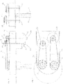
- the kneading machine described herein designated as a whole by the reference number 10, comprises two kneading tools 2, 4, which rotate about respective, preferably fixed, axes of rotation I1, 12.
- the machine described herein may in any case even present a larger number of tools, and the teachings that will be presented hereinafter with reference to the tools 2, 4 may be applied in the same way to all the tools.
- the two kneading tools 2, 4 are mounted and turn on a top structure 12 of the kneading machine, which extends horizontally, in cantilever fashion, setting the two tools 2, 4 above a region S that is to house a bowl (not illustrated) containing the ingredients for preparation of the dough.
- a top structure 12 of the kneading machine which extends horizontally, in cantilever fashion, setting the two tools 2, 4 above a region S that is to house a bowl (not illustrated) containing the ingredients for preparation of the dough.
- the machine 10 comprises two driving units 6, 8, for example two electric motors, which are each prearranged for actuating a respective one of the two tools 2 and 4.
- the two driving units 6, 8 can be connected to the respective tools 2, 4 in any way known to the person skilled in the sector.
- the two motors 6, 8 are mounted on a proximal region of the top structure 12, according to an arrangement such that the axes of rotation 13, I4 of the rotors of the two motors are parallel to one another and to the two axes of rotation I1, I2 of the two kneading tools 2, 4.
- the output shafts 6A, 8A of the two motors are connected in rotation to the two tools 2, 4 through a belt-transmission system.
- the two kneading tools 2, 4 are fixed to the bottom ends of two respective shafts 22, 24, which are rotatably mounted on the structure 12 so as to turn about the two axes of rotation I1, 12.
- the two shafts 22, 24 have, fitted on them, respective pulleys 26, 28, which are connected via the belts 32, 34 to the pulleys 36, 38, respectively, which are in turn fitted on the shafts 6A, 8A of the two electric motors 6, 8.
- the two driving units 6, 8 may, instead, be directly connected to the two kneading tools 2, 4; in this case, for example, the two motors 6, 8 are arranged with their own axes of rotation 13, I4 aligned to the two axes of rotation I1, I2 of the two kneading tools.
- the kneading machine 10 comprises at least two sensors 102, 104, 44 with the function of detecting a datum indicating the velocity and/or position of the two kneading tools 2, 4.
- the two sensors 102, 104 are, for example, two encoders.
- the kneading machine 10 comprises a control unit 100 (see Figure 8 ) configured to control the two driving units 6, 8 so as to operate the two kneading tools 2, 4 for execution of a kneading action.
- the two kneading tools 2, 4 are prearranged for assuming, instant by instant, a respective phase or angular position about the corresponding axes of rotation, creating between them a phase difference necessary for them to carry out an effective kneading action.
- Figure 5A represents a "snapshot" of the two kneading tools 2, 4 driven in rotation by the motors 6, 8, where the tool 2 is in the angular position of 320°, the tool 4 is in the angular position of 180°, and their phase difference is equal to 40°. As indicated in the figure, these angular values are determined with respect to a reference axis R perpendicular to the axis of rotation of the tool.
- the phase difference indicated determines, in the positions reached by the two tools at the instant represented, a minimum distance D respective portions 2A, 4A of the two tools.
- the condition represented in Figure 5A corresponds to a position in which two corresponding portions (the two portions 2A and 4A in the example illustrated) of the two tools are at a minimum distance from all the other positions assumed by the two tools during their rotation.
- the portions 2A, 4A are active portions of the tools during kneading of the dough, which are set in corresponding positions along the corresponding axes of rotation I1, 12.
- the kneading machine 10 is prearranged for adjusting the phase difference between the two kneading tools 2, 4 according to the requirements of the specific applications.
- control unit 100 is configured to control the two driving unit 6, 8 on the basis of the signals coming from the sensors 102 and 104 so as to operate the two tools 2, 4 according to a reference phase difference.
- the reference phase difference can be selected by the operator or else can be determined by the machine on the basis of one or more data inherent in the specific application. In some applications, the phase difference may even be equal to 0°, the two tools being in this case at the minimum distance apart possible (clearly, this is possible when the orbits of rotation of the two tools do not interpenetrate).
- the kneading machine may, for example, envisage a user-interface device prearranged for enabling the operator to enter a datum regarding a required phase difference.
- the user-interface device is prearranged for entering one or more data regarding:
- the machine 10 comprises a control unit configured to determine a reference phase difference on the basis of one or more of the aforesaid data.
- the kneading machine 10 is moreover prearranged for adjusting the phase difference of the kneading tools 2, 4 during the kneading cycle.
- control unit is configured to receive a signal indicating a reference phase difference and to modify the velocity of rotation of at least one of the two tools 2, 4 as a function of the aforesaid signal until a phase difference of the two tools is achieved that corresponds to the reference phase difference.
- the user-interface device of the kneading machine 10 is prearranged for enabling application of a required phase difference during the work cycle of the machine.
- the machine comprises a memory unit containing a temporal sequence of reference phase differences on the basis of which the control unit 100 carries out control of the driving unit 6, 8 during the work cycle of the machine.
- the memory unit comprises a plurality of kneading programmes, each having a time sequence of reference phase differences.
- a control unit of the machine is configured to select one of the kneading programmes on the basis of one or more data regarding one or more of the following conditions:
- the kneading machine 10 comprises a sensor designed to detect a parameter indicating the kneading action performed by the two tools 2, 4, and the control unit 100 is configured to modify the velocity of rotation of the two tools 2, 4 as a function of the signal coming from the aforesaid sensor so as to pass from a first reference phase difference to a second reference phase difference between the two kneading tools 2, 4.
- Said sensor may, for example, be a timer designed to detect a pre-set kneading time.
- phase difference corresponding to the above different conditions of phase difference are different values of the distance D between the portions 2A and 4A of the two tools, in particular the increase of the phase difference corresponding to a proportional increase of the distance D.
- the kneading machine 10 can hence adjust the phase difference between the two tools on the basis of specific requirements of application.
- the phase difference between the tools 2, 4 may be determined on the basis of one or more of the following conditions:
- the two kneading tools 2, 4 can operate with a difference in angle that is very small at the start of the kneading cycle and then increases as the gluten is formed in the dough, or, vice versa, the difference in angle can start from a high value and decrease.
- Experimental tests conducted by the present applicant have shown that this operating mode enables significant reduction in the duration of the kneading cycle.
- Figures 1 to 5A-5C illustrate an example of embodiment in which the kneading machine 10 is equipped with two tools having individual rectilinear main portions oriented in a direction parallel to the corresponding axes of rotation.
- the two tools 2, 4 have corresponding orbits that interpenetrate and, in the example illustrated, are driven in discordant directions of rotation.
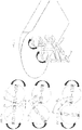
- Figure 6 illustrates, instead, a variant in which the two tools 2, 4 have more complex profiles that develop in planes containing the corresponding axes of rotation.
- the two tools 2, 4 define orbits that do not interpenetrate, but are set at a distance apart, and are driven in concordant directions of rotation.
- the two tools 2, 4 are also different from one another.
- Figures 7A-7C illustrate the two tools 2, 4 in different conditions of mutual phase difference, 0°, 45°, 90°, corresponding to which are different values of the distance D between the portions 2A and 4A of the two tools.
- the system illustrated envisages two inverters 106 and 108 for supplying, respectively, the two motors 6, 8, and two encoders 102 and 104 associated, respectively, to the two motors 6, 8 for detecting their velocity of rotation and their positions.
- the two encoders correspond to the sensors 102, 104 referred to previously.
- a control module 110 receives at input a reference velocity ⁇ R and issues to the inverters 106 and 108 signals for actuation of the two motors 6, 8 at a velocity of rotation corresponding to the reference velocity.
- the control system further comprises a module 112 prearranged for receiving at input the angular positions ⁇ 1, ⁇ 2 of the two kneading tools 2, 4 and designed to determine the effective phase difference ⁇ M of the two tools.
- a further control module 114 receives at input a reference phase difference ⁇ R and the phase difference ⁇ M calculated by the module 112, and is designed to transmit to the control module 110 a command signal ⁇ ⁇ for a change in peed.
- the modules 110, 112 and 114 form part of the control unit 100 mentioned above.
- the reference phase difference ⁇ R may, for example, come from the user-device interface of the machine, designated by the reference 120 in Figure 8 , through which the operator has entered a required phase difference.
- the module 114 When at input to the module 114 a reference phase difference ⁇ R is received that differs from the effective phase difference of the two tools, the module 114 transmits to the module 110 a command signal for a change in velocity.
- the module 110 carries out an action of control of the velocities of the two kneading tools 2, 4 in such a way that these velocities differ from one another until between the two tools the reference phase difference ⁇ R is obtained, at which point the reference velocity ⁇ R is set for both tools.
- control module 110 can vary the velocity of just one or else both of the tools 2, 4. For instance, the module 110 can accelerate or decelerate one of the two tools or else simultaneously accelerate one and decelerate the other.
- the reference phase difference ⁇ R may correspond to the required phase difference or else may be determined by the machine according to the modalities described above.
Landscapes
- Chemical & Material Sciences (AREA)
- Chemical Kinetics & Catalysis (AREA)
- Life Sciences & Earth Sciences (AREA)
- Engineering & Computer Science (AREA)
- Food Science & Technology (AREA)
- Biophysics (AREA)
- Manufacturing And Processing Devices For Dough (AREA)
- Road Repair (AREA)
- Electrical Discharge Machining, Electrochemical Machining, And Combined Machining (AREA)
- Confectionery (AREA)
Applications Claiming Priority (1)
| Application Number | Priority Date | Filing Date | Title |
|---|---|---|---|
| IT102020000003413A IT202000003413A1 (it) | 2020-02-19 | 2020-02-19 | Macchina impastatrice |
Publications (2)
| Publication Number | Publication Date |
|---|---|
| EP3868209A1 true EP3868209A1 (fr) | 2021-08-25 |
| EP3868209B1 EP3868209B1 (fr) | 2023-07-26 |
Family
ID=70738855
Family Applications (1)
| Application Number | Title | Priority Date | Filing Date |
|---|---|---|---|
| EP21156250.9A Active EP3868209B1 (fr) | 2020-02-19 | 2021-02-10 | Machine à pétrir et procédé de production de pâte |
Country Status (2)
| Country | Link |
|---|---|
| EP (1) | EP3868209B1 (fr) |
| IT (1) | IT202000003413A1 (fr) |
Cited By (1)
| Publication number | Priority date | Publication date | Assignee | Title |
|---|---|---|---|---|
| AT526679B1 (de) * | 2023-04-06 | 2024-06-15 | Maschf Laska Gesellschaft M B H | Verfahren zum Steuern einer Mischvorrichtung |
Citations (3)
| Publication number | Priority date | Publication date | Assignee | Title |
|---|---|---|---|---|
| US3656718A (en) * | 1970-07-30 | 1972-04-18 | Dynamics Corp America | Helical blade mixer |
| EP2269802A1 (fr) * | 2008-04-08 | 2011-01-05 | Moriyama Co., Ltd. | Extrudeuse à deux arbres |
| EP3450007A1 (fr) * | 2016-04-25 | 2019-03-06 | Metatek Co., Ltd. | Agitateur comprenant deux arbres rotatifs ayant des lames d'agitation se croisant capables de tourner symétriquement et de tourner dans une direction identique, et procédé d'agitation |
-
2020
- 2020-02-19 IT IT102020000003413A patent/IT202000003413A1/it unknown
-
2021
- 2021-02-10 EP EP21156250.9A patent/EP3868209B1/fr active Active
Patent Citations (3)
| Publication number | Priority date | Publication date | Assignee | Title |
|---|---|---|---|---|
| US3656718A (en) * | 1970-07-30 | 1972-04-18 | Dynamics Corp America | Helical blade mixer |
| EP2269802A1 (fr) * | 2008-04-08 | 2011-01-05 | Moriyama Co., Ltd. | Extrudeuse à deux arbres |
| EP3450007A1 (fr) * | 2016-04-25 | 2019-03-06 | Metatek Co., Ltd. | Agitateur comprenant deux arbres rotatifs ayant des lames d'agitation se croisant capables de tourner symétriquement et de tourner dans une direction identique, et procédé d'agitation |
Cited By (2)
| Publication number | Priority date | Publication date | Assignee | Title |
|---|---|---|---|---|
| AT526679B1 (de) * | 2023-04-06 | 2024-06-15 | Maschf Laska Gesellschaft M B H | Verfahren zum Steuern einer Mischvorrichtung |
| AT526679A4 (de) * | 2023-04-06 | 2024-06-15 | Maschf Laska Gesellschaft M B H | Verfahren zum Steuern einer Mischvorrichtung |
Also Published As
| Publication number | Publication date |
|---|---|
| IT202000003413A1 (it) | 2021-08-19 |
| EP3868209B1 (fr) | 2023-07-26 |
Similar Documents
| Publication | Publication Date | Title |
|---|---|---|
| CN106863266B (zh) | 机器人、控制装置以及机器人系统 | |
| US4277731A (en) | Wrapping machine | |
| JP2009213190A (ja) | モータ装置 | |
| EP3868209B1 (fr) | Machine à pétrir et procédé de production de pâte | |
| JP2761426B2 (ja) | 数値制御装置 | |
| JPH02256483A (ja) | 産業用ロボットの速度制御装置 | |
| EP0135772B1 (fr) | Dispositif pour le contrôle de mouvements pour un robot | |
| US20020188381A1 (en) | Control system for robots | |
| US7992688B2 (en) | Door device for an elevator | |
| US20230033189A1 (en) | Minimally invasive surgical robot master manipulator and slave manipulator control method | |
| CN103914067A (zh) | 一种控制方法及电子设备 | |
| CN211862956U (zh) | 一种微创手术机器人主手 | |
| EP2495626A1 (fr) | Procédé de contrôle de commande électrique d'une machine de fabrication automatique et machine de fabrication automatique à contrôle de commande électrique | |
| CN113216997B (zh) | 电机驱动式偏心刀盘的转动位置控制方法 | |
| CN117598794A (zh) | 操控装置、手术机器人及手术机器人开合角度的校正方法 | |
| EP3919994B1 (fr) | Dispositif de commande | |
| JPS63286705A (ja) | ロボットの位置検出方法 | |
| JPS63260757A (ja) | ワイヤソ−装置 | |
| JPH0331906A (ja) | 数値制御装置 | |
| JP2003088184A (ja) | 複数軸制御装置及びその軸間同期方法 | |
| JP3388426B2 (ja) | 任意補間を可能としたモータのパルス列制御方式 | |
| JP2819411B2 (ja) | 定位置停止制御装置 | |
| US20240361777A1 (en) | Gyro unit and steering system | |
| JPS62155786A (ja) | 同期ずれ検出方法 | |
| KR101201725B1 (ko) | 매니퓰레이터 |
Legal Events
| Date | Code | Title | Description |
|---|---|---|---|
| PUAI | Public reference made under article 153(3) epc to a published international application that has entered the european phase |
Free format text: ORIGINAL CODE: 0009012 |
|
| STAA | Information on the status of an ep patent application or granted ep patent |
Free format text: STATUS: THE APPLICATION HAS BEEN PUBLISHED |
|
| AK | Designated contracting states |
Kind code of ref document: A1 Designated state(s): AL AT BE BG CH CY CZ DE DK EE ES FI FR GB GR HR HU IE IS IT LI LT LU LV MC MK MT NL NO PL PT RO RS SE SI SK SM TR |
|
| STAA | Information on the status of an ep patent application or granted ep patent |
Free format text: STATUS: REQUEST FOR EXAMINATION WAS MADE |
|
| 17P | Request for examination filed |
Effective date: 20220208 |
|
| RBV | Designated contracting states (corrected) |
Designated state(s): AL AT BE BG CH CY CZ DE DK EE ES FI FR GB GR HR HU IE IS IT LI LT LU LV MC MK MT NL NO PL PT RO RS SE SI SK SM TR |
|
| GRAP | Despatch of communication of intention to grant a patent |
Free format text: ORIGINAL CODE: EPIDOSNIGR1 |
|
| STAA | Information on the status of an ep patent application or granted ep patent |
Free format text: STATUS: GRANT OF PATENT IS INTENDED |
|
| RIC1 | Information provided on ipc code assigned before grant |
Ipc: B01F 35/221 20220101ALI20230125BHEP Ipc: B01F 35/212 20220101ALI20230125BHEP Ipc: B01F 27/96 20220101ALI20230125BHEP Ipc: B01F 27/85 20220101ALI20230125BHEP Ipc: B01F 27/2322 20220101ALI20230125BHEP Ipc: A21C 1/14 20060101ALI20230125BHEP Ipc: A21C 1/02 20060101AFI20230125BHEP |
|
| INTG | Intention to grant announced |
Effective date: 20230224 |
|
| GRAS | Grant fee paid |
Free format text: ORIGINAL CODE: EPIDOSNIGR3 |
|
| GRAA | (expected) grant |
Free format text: ORIGINAL CODE: 0009210 |
|
| STAA | Information on the status of an ep patent application or granted ep patent |
Free format text: STATUS: THE PATENT HAS BEEN GRANTED |
|
| AK | Designated contracting states |
Kind code of ref document: B1 Designated state(s): AL AT BE BG CH CY CZ DE DK EE ES FI FR GB GR HR HU IE IS IT LI LT LU LV MC MK MT NL NO PL PT RO RS SE SI SK SM TR |
|
| REG | Reference to a national code |
Ref country code: CH Ref legal event code: EP |
|
| REG | Reference to a national code |
Ref country code: IE Ref legal event code: FG4D |
|
| REG | Reference to a national code |
Ref country code: DE Ref legal event code: R096 Ref document number: 602021003675 Country of ref document: DE |
|
| REG | Reference to a national code |
Ref country code: LT Ref legal event code: MG9D |
|
| REG | Reference to a national code |
Ref country code: NL Ref legal event code: MP Effective date: 20230726 |
|
| REG | Reference to a national code |
Ref country code: AT Ref legal event code: MK05 Ref document number: 1590851 Country of ref document: AT Kind code of ref document: T Effective date: 20230726 |
|
| PG25 | Lapsed in a contracting state [announced via postgrant information from national office to epo] |
Ref country code: NL Free format text: LAPSE BECAUSE OF FAILURE TO SUBMIT A TRANSLATION OF THE DESCRIPTION OR TO PAY THE FEE WITHIN THE PRESCRIBED TIME-LIMIT Effective date: 20230726 |
|
| PG25 | Lapsed in a contracting state [announced via postgrant information from national office to epo] |
Ref country code: GR Free format text: LAPSE BECAUSE OF FAILURE TO SUBMIT A TRANSLATION OF THE DESCRIPTION OR TO PAY THE FEE WITHIN THE PRESCRIBED TIME-LIMIT Effective date: 20231027 |
|
| PG25 | Lapsed in a contracting state [announced via postgrant information from national office to epo] |
Ref country code: IS Free format text: LAPSE BECAUSE OF FAILURE TO SUBMIT A TRANSLATION OF THE DESCRIPTION OR TO PAY THE FEE WITHIN THE PRESCRIBED TIME-LIMIT Effective date: 20231126 |
|
| PG25 | Lapsed in a contracting state [announced via postgrant information from national office to epo] |
Ref country code: SE Free format text: LAPSE BECAUSE OF FAILURE TO SUBMIT A TRANSLATION OF THE DESCRIPTION OR TO PAY THE FEE WITHIN THE PRESCRIBED TIME-LIMIT Effective date: 20230726 Ref country code: RS Free format text: LAPSE BECAUSE OF FAILURE TO SUBMIT A TRANSLATION OF THE DESCRIPTION OR TO PAY THE FEE WITHIN THE PRESCRIBED TIME-LIMIT Effective date: 20230726 Ref country code: PT Free format text: LAPSE BECAUSE OF FAILURE TO SUBMIT A TRANSLATION OF THE DESCRIPTION OR TO PAY THE FEE WITHIN THE PRESCRIBED TIME-LIMIT Effective date: 20231127 Ref country code: NO Free format text: LAPSE BECAUSE OF FAILURE TO SUBMIT A TRANSLATION OF THE DESCRIPTION OR TO PAY THE FEE WITHIN THE PRESCRIBED TIME-LIMIT Effective date: 20231026 Ref country code: LV Free format text: LAPSE BECAUSE OF FAILURE TO SUBMIT A TRANSLATION OF THE DESCRIPTION OR TO PAY THE FEE WITHIN THE PRESCRIBED TIME-LIMIT Effective date: 20230726 Ref country code: LT Free format text: LAPSE BECAUSE OF FAILURE TO SUBMIT A TRANSLATION OF THE DESCRIPTION OR TO PAY THE FEE WITHIN THE PRESCRIBED TIME-LIMIT Effective date: 20230726 Ref country code: IS Free format text: LAPSE BECAUSE OF FAILURE TO SUBMIT A TRANSLATION OF THE DESCRIPTION OR TO PAY THE FEE WITHIN THE PRESCRIBED TIME-LIMIT Effective date: 20231126 Ref country code: HR Free format text: LAPSE BECAUSE OF FAILURE TO SUBMIT A TRANSLATION OF THE DESCRIPTION OR TO PAY THE FEE WITHIN THE PRESCRIBED TIME-LIMIT Effective date: 20230726 Ref country code: GR Free format text: LAPSE BECAUSE OF FAILURE TO SUBMIT A TRANSLATION OF THE DESCRIPTION OR TO PAY THE FEE WITHIN THE PRESCRIBED TIME-LIMIT Effective date: 20231027 Ref country code: FI Free format text: LAPSE BECAUSE OF FAILURE TO SUBMIT A TRANSLATION OF THE DESCRIPTION OR TO PAY THE FEE WITHIN THE PRESCRIBED TIME-LIMIT Effective date: 20230726 Ref country code: AT Free format text: LAPSE BECAUSE OF FAILURE TO SUBMIT A TRANSLATION OF THE DESCRIPTION OR TO PAY THE FEE WITHIN THE PRESCRIBED TIME-LIMIT Effective date: 20230726 |
|
| PG25 | Lapsed in a contracting state [announced via postgrant information from national office to epo] |
Ref country code: PL Free format text: LAPSE BECAUSE OF FAILURE TO SUBMIT A TRANSLATION OF THE DESCRIPTION OR TO PAY THE FEE WITHIN THE PRESCRIBED TIME-LIMIT Effective date: 20230726 |
|
| PG25 | Lapsed in a contracting state [announced via postgrant information from national office to epo] |
Ref country code: ES Free format text: LAPSE BECAUSE OF FAILURE TO SUBMIT A TRANSLATION OF THE DESCRIPTION OR TO PAY THE FEE WITHIN THE PRESCRIBED TIME-LIMIT Effective date: 20230726 |
|
| REG | Reference to a national code |
Ref country code: DE Ref legal event code: R097 Ref document number: 602021003675 Country of ref document: DE |
|
| PG25 | Lapsed in a contracting state [announced via postgrant information from national office to epo] |
Ref country code: SM Free format text: LAPSE BECAUSE OF FAILURE TO SUBMIT A TRANSLATION OF THE DESCRIPTION OR TO PAY THE FEE WITHIN THE PRESCRIBED TIME-LIMIT Effective date: 20230726 Ref country code: RO Free format text: LAPSE BECAUSE OF FAILURE TO SUBMIT A TRANSLATION OF THE DESCRIPTION OR TO PAY THE FEE WITHIN THE PRESCRIBED TIME-LIMIT Effective date: 20230726 Ref country code: ES Free format text: LAPSE BECAUSE OF FAILURE TO SUBMIT A TRANSLATION OF THE DESCRIPTION OR TO PAY THE FEE WITHIN THE PRESCRIBED TIME-LIMIT Effective date: 20230726 Ref country code: EE Free format text: LAPSE BECAUSE OF FAILURE TO SUBMIT A TRANSLATION OF THE DESCRIPTION OR TO PAY THE FEE WITHIN THE PRESCRIBED TIME-LIMIT Effective date: 20230726 Ref country code: DK Free format text: LAPSE BECAUSE OF FAILURE TO SUBMIT A TRANSLATION OF THE DESCRIPTION OR TO PAY THE FEE WITHIN THE PRESCRIBED TIME-LIMIT Effective date: 20230726 Ref country code: CZ Free format text: LAPSE BECAUSE OF FAILURE TO SUBMIT A TRANSLATION OF THE DESCRIPTION OR TO PAY THE FEE WITHIN THE PRESCRIBED TIME-LIMIT Effective date: 20230726 Ref country code: SK Free format text: LAPSE BECAUSE OF FAILURE TO SUBMIT A TRANSLATION OF THE DESCRIPTION OR TO PAY THE FEE WITHIN THE PRESCRIBED TIME-LIMIT Effective date: 20230726 |
|
| PLBE | No opposition filed within time limit |
Free format text: ORIGINAL CODE: 0009261 |
|
| STAA | Information on the status of an ep patent application or granted ep patent |
Free format text: STATUS: NO OPPOSITION FILED WITHIN TIME LIMIT |
|
| 26N | No opposition filed |
Effective date: 20240429 |
|
| PG25 | Lapsed in a contracting state [announced via postgrant information from national office to epo] |
Ref country code: SI Free format text: LAPSE BECAUSE OF FAILURE TO SUBMIT A TRANSLATION OF THE DESCRIPTION OR TO PAY THE FEE WITHIN THE PRESCRIBED TIME-LIMIT Effective date: 20230726 |
|
| PG25 | Lapsed in a contracting state [announced via postgrant information from national office to epo] |
Ref country code: MC Free format text: LAPSE BECAUSE OF FAILURE TO SUBMIT A TRANSLATION OF THE DESCRIPTION OR TO PAY THE FEE WITHIN THE PRESCRIBED TIME-LIMIT Effective date: 20230726 |
|
| REG | Reference to a national code |
Ref country code: CH Ref legal event code: PL |
|
| PG25 | Lapsed in a contracting state [announced via postgrant information from national office to epo] |
Ref country code: LU Free format text: LAPSE BECAUSE OF NON-PAYMENT OF DUE FEES Effective date: 20240210 |
|
| PG25 | Lapsed in a contracting state [announced via postgrant information from national office to epo] |
Ref country code: CH Free format text: LAPSE BECAUSE OF NON-PAYMENT OF DUE FEES Effective date: 20240229 |
|
| PG25 | Lapsed in a contracting state [announced via postgrant information from national office to epo] |
Ref country code: LU Free format text: LAPSE BECAUSE OF NON-PAYMENT OF DUE FEES Effective date: 20240210 Ref country code: CH Free format text: LAPSE BECAUSE OF NON-PAYMENT OF DUE FEES Effective date: 20240229 |
|
| PG25 | Lapsed in a contracting state [announced via postgrant information from national office to epo] |
Ref country code: BG Free format text: LAPSE BECAUSE OF FAILURE TO SUBMIT A TRANSLATION OF THE DESCRIPTION OR TO PAY THE FEE WITHIN THE PRESCRIBED TIME-LIMIT Effective date: 20230726 |
|
| PG25 | Lapsed in a contracting state [announced via postgrant information from national office to epo] |
Ref country code: BG Free format text: LAPSE BECAUSE OF FAILURE TO SUBMIT A TRANSLATION OF THE DESCRIPTION OR TO PAY THE FEE WITHIN THE PRESCRIBED TIME-LIMIT Effective date: 20230726 |
|
| REG | Reference to a national code |
Ref country code: BE Ref legal event code: MM Effective date: 20240229 |
|
| PG25 | Lapsed in a contracting state [announced via postgrant information from national office to epo] |
Ref country code: BE Free format text: LAPSE BECAUSE OF NON-PAYMENT OF DUE FEES Effective date: 20240229 |
|
| PG25 | Lapsed in a contracting state [announced via postgrant information from national office to epo] |
Ref country code: IE Free format text: LAPSE BECAUSE OF NON-PAYMENT OF DUE FEES Effective date: 20240210 |
|
| PG25 | Lapsed in a contracting state [announced via postgrant information from national office to epo] |
Ref country code: IE Free format text: LAPSE BECAUSE OF NON-PAYMENT OF DUE FEES Effective date: 20240210 Ref country code: BE Free format text: LAPSE BECAUSE OF NON-PAYMENT OF DUE FEES Effective date: 20240229 |
|
| PG25 | Lapsed in a contracting state [announced via postgrant information from national office to epo] |
Ref country code: CY Free format text: LAPSE BECAUSE OF FAILURE TO SUBMIT A TRANSLATION OF THE DESCRIPTION OR TO PAY THE FEE WITHIN THE PRESCRIBED TIME-LIMIT; INVALID AB INITIO Effective date: 20210210 |
|
| PG25 | Lapsed in a contracting state [announced via postgrant information from national office to epo] |
Ref country code: HU Free format text: LAPSE BECAUSE OF FAILURE TO SUBMIT A TRANSLATION OF THE DESCRIPTION OR TO PAY THE FEE WITHIN THE PRESCRIBED TIME-LIMIT; INVALID AB INITIO Effective date: 20210210 |
|
| GBPC | Gb: european patent ceased through non-payment of renewal fee |
Effective date: 20250210 |
|
| PG25 | Lapsed in a contracting state [announced via postgrant information from national office to epo] |
Ref country code: TR Free format text: LAPSE BECAUSE OF FAILURE TO SUBMIT A TRANSLATION OF THE DESCRIPTION OR TO PAY THE FEE WITHIN THE PRESCRIBED TIME-LIMIT Effective date: 20230726 |
|
| PG25 | Lapsed in a contracting state [announced via postgrant information from national office to epo] |
Ref country code: GB Free format text: LAPSE BECAUSE OF NON-PAYMENT OF DUE FEES Effective date: 20250210 |
|
| PGFP | Annual fee paid to national office [announced via postgrant information from national office to epo] |
Ref country code: DE Payment date: 20260220 Year of fee payment: 6 |
|
| PGFP | Annual fee paid to national office [announced via postgrant information from national office to epo] |
Ref country code: IT Payment date: 20260203 Year of fee payment: 6 |
|
| PGFP | Annual fee paid to national office [announced via postgrant information from national office to epo] |
Ref country code: FR Payment date: 20260227 Year of fee payment: 6 |