EP2269802A1 - Extrudeuse à deux arbres - Google Patents
Extrudeuse à deux arbres Download PDFInfo
- Publication number
- EP2269802A1 EP2269802A1 EP08873882A EP08873882A EP2269802A1 EP 2269802 A1 EP2269802 A1 EP 2269802A1 EP 08873882 A EP08873882 A EP 08873882A EP 08873882 A EP08873882 A EP 08873882A EP 2269802 A1 EP2269802 A1 EP 2269802A1
- Authority
- EP
- European Patent Office
- Prior art keywords
- abutment member
- phase difference
- pair
- projecting portions
- rotor
- Prior art date
- Legal status (The legal status is an assumption and is not a legal conclusion. Google has not performed a legal analysis and makes no representation as to the accuracy of the status listed.)
- Granted
Links
Images

Classifications
-
- B—PERFORMING OPERATIONS; TRANSPORTING
- B29—WORKING OF PLASTICS; WORKING OF SUBSTANCES IN A PLASTIC STATE IN GENERAL
- B29C—SHAPING OR JOINING OF PLASTICS; SHAPING OF MATERIAL IN A PLASTIC STATE, NOT OTHERWISE PROVIDED FOR; AFTER-TREATMENT OF THE SHAPED PRODUCTS, e.g. REPAIRING
- B29C48/00—Extrusion moulding, i.e. expressing the moulding material through a die or nozzle which imparts the desired form; Apparatus therefor
- B29C48/25—Component parts, details or accessories; Auxiliary operations
- B29C48/36—Means for plasticising or homogenising the moulding material or forcing it through the nozzle or die
- B29C48/395—Means for plasticising or homogenising the moulding material or forcing it through the nozzle or die using screws surrounded by a cooperating barrel, e.g. single screw extruders
- B29C48/40—Means for plasticising or homogenising the moulding material or forcing it through the nozzle or die using screws surrounded by a cooperating barrel, e.g. single screw extruders using two or more parallel screws or at least two parallel non-intermeshing screws, e.g. twin screw extruders
- B29C48/402—Means for plasticising or homogenising the moulding material or forcing it through the nozzle or die using screws surrounded by a cooperating barrel, e.g. single screw extruders using two or more parallel screws or at least two parallel non-intermeshing screws, e.g. twin screw extruders the screws having intermeshing parts
-
- B—PERFORMING OPERATIONS; TRANSPORTING
- B29—WORKING OF PLASTICS; WORKING OF SUBSTANCES IN A PLASTIC STATE IN GENERAL
- B29B—PREPARATION OR PRETREATMENT OF THE MATERIAL TO BE SHAPED; MAKING GRANULES OR PREFORMS; RECOVERY OF PLASTICS OR OTHER CONSTITUENTS OF WASTE MATERIAL CONTAINING PLASTICS
- B29B7/00—Mixing; Kneading
- B29B7/30—Mixing; Kneading continuous, with mechanical mixing or kneading devices
- B29B7/34—Mixing; Kneading continuous, with mechanical mixing or kneading devices with movable mixing or kneading devices
- B29B7/38—Mixing; Kneading continuous, with mechanical mixing or kneading devices with movable mixing or kneading devices rotary
- B29B7/46—Mixing; Kneading continuous, with mechanical mixing or kneading devices with movable mixing or kneading devices rotary with more than one shaft
- B29B7/48—Mixing; Kneading continuous, with mechanical mixing or kneading devices with movable mixing or kneading devices rotary with more than one shaft with intermeshing devices, e.g. screws
- B29B7/484—Mixing; Kneading continuous, with mechanical mixing or kneading devices with movable mixing or kneading devices rotary with more than one shaft with intermeshing devices, e.g. screws with two shafts provided with screws, e.g. one screw being shorter than the other
-
- B—PERFORMING OPERATIONS; TRANSPORTING
- B29—WORKING OF PLASTICS; WORKING OF SUBSTANCES IN A PLASTIC STATE IN GENERAL
- B29B—PREPARATION OR PRETREATMENT OF THE MATERIAL TO BE SHAPED; MAKING GRANULES OR PREFORMS; RECOVERY OF PLASTICS OR OTHER CONSTITUENTS OF WASTE MATERIAL CONTAINING PLASTICS
- B29B7/00—Mixing; Kneading
- B29B7/30—Mixing; Kneading continuous, with mechanical mixing or kneading devices
- B29B7/34—Mixing; Kneading continuous, with mechanical mixing or kneading devices with movable mixing or kneading devices
- B29B7/38—Mixing; Kneading continuous, with mechanical mixing or kneading devices with movable mixing or kneading devices rotary
- B29B7/46—Mixing; Kneading continuous, with mechanical mixing or kneading devices with movable mixing or kneading devices rotary with more than one shaft
- B29B7/48—Mixing; Kneading continuous, with mechanical mixing or kneading devices with movable mixing or kneading devices rotary with more than one shaft with intermeshing devices, e.g. screws
- B29B7/488—Parts, e.g. casings, sealings; Accessories, e.g. flow controlling or throttling devices
- B29B7/489—Screws
-
- B—PERFORMING OPERATIONS; TRANSPORTING
- B29—WORKING OF PLASTICS; WORKING OF SUBSTANCES IN A PLASTIC STATE IN GENERAL
- B29B—PREPARATION OR PRETREATMENT OF THE MATERIAL TO BE SHAPED; MAKING GRANULES OR PREFORMS; RECOVERY OF PLASTICS OR OTHER CONSTITUENTS OF WASTE MATERIAL CONTAINING PLASTICS
- B29B7/00—Mixing; Kneading
- B29B7/30—Mixing; Kneading continuous, with mechanical mixing or kneading devices
- B29B7/58—Component parts, details or accessories; Auxiliary operations
- B29B7/60—Component parts, details or accessories; Auxiliary operations for feeding, e.g. end guides for the incoming material
-
- B—PERFORMING OPERATIONS; TRANSPORTING
- B29—WORKING OF PLASTICS; WORKING OF SUBSTANCES IN A PLASTIC STATE IN GENERAL
- B29B—PREPARATION OR PRETREATMENT OF THE MATERIAL TO BE SHAPED; MAKING GRANULES OR PREFORMS; RECOVERY OF PLASTICS OR OTHER CONSTITUENTS OF WASTE MATERIAL CONTAINING PLASTICS
- B29B7/00—Mixing; Kneading
- B29B7/30—Mixing; Kneading continuous, with mechanical mixing or kneading devices
- B29B7/58—Component parts, details or accessories; Auxiliary operations
- B29B7/72—Measuring, controlling or regulating
- B29B7/728—Measuring data of the driving system, e.g. torque, speed, power, vibration
-
- B—PERFORMING OPERATIONS; TRANSPORTING
- B29—WORKING OF PLASTICS; WORKING OF SUBSTANCES IN A PLASTIC STATE IN GENERAL
- B29C—SHAPING OR JOINING OF PLASTICS; SHAPING OF MATERIAL IN A PLASTIC STATE, NOT OTHERWISE PROVIDED FOR; AFTER-TREATMENT OF THE SHAPED PRODUCTS, e.g. REPAIRING
- B29C48/00—Extrusion moulding, i.e. expressing the moulding material through a die or nozzle which imparts the desired form; Apparatus therefor
- B29C48/25—Component parts, details or accessories; Auxiliary operations
- B29C48/252—Drive or actuation means; Transmission means; Screw supporting means
-
- B—PERFORMING OPERATIONS; TRANSPORTING
- B29—WORKING OF PLASTICS; WORKING OF SUBSTANCES IN A PLASTIC STATE IN GENERAL
- B29C—SHAPING OR JOINING OF PLASTICS; SHAPING OF MATERIAL IN A PLASTIC STATE, NOT OTHERWISE PROVIDED FOR; AFTER-TREATMENT OF THE SHAPED PRODUCTS, e.g. REPAIRING
- B29C48/00—Extrusion moulding, i.e. expressing the moulding material through a die or nozzle which imparts the desired form; Apparatus therefor
- B29C48/25—Component parts, details or accessories; Auxiliary operations
- B29C48/36—Means for plasticising or homogenising the moulding material or forcing it through the nozzle or die
- B29C48/50—Details of extruders
- B29C48/505—Screws
- B29C48/52—Screws with an outer diameter varying along the longitudinal axis, e.g. for obtaining different thread clearance
- B29C48/525—Conical screws
-
- B—PERFORMING OPERATIONS; TRANSPORTING
- B29—WORKING OF PLASTICS; WORKING OF SUBSTANCES IN A PLASTIC STATE IN GENERAL
- B29C—SHAPING OR JOINING OF PLASTICS; SHAPING OF MATERIAL IN A PLASTIC STATE, NOT OTHERWISE PROVIDED FOR; AFTER-TREATMENT OF THE SHAPED PRODUCTS, e.g. REPAIRING
- B29C48/00—Extrusion moulding, i.e. expressing the moulding material through a die or nozzle which imparts the desired form; Apparatus therefor
- B29C48/25—Component parts, details or accessories; Auxiliary operations
- B29C48/92—Measuring, controlling or regulating
-
- B—PERFORMING OPERATIONS; TRANSPORTING
- B29—WORKING OF PLASTICS; WORKING OF SUBSTANCES IN A PLASTIC STATE IN GENERAL
- B29B—PREPARATION OR PRETREATMENT OF THE MATERIAL TO BE SHAPED; MAKING GRANULES OR PREFORMS; RECOVERY OF PLASTICS OR OTHER CONSTITUENTS OF WASTE MATERIAL CONTAINING PLASTICS
- B29B7/00—Mixing; Kneading
- B29B7/74—Mixing; Kneading using other mixers or combinations of mixers, e.g. of dissimilar mixers ; Plant
- B29B7/7476—Systems, i.e. flow charts or diagrams; Plants
- B29B7/7495—Systems, i.e. flow charts or diagrams; Plants for mixing rubber
-
- B—PERFORMING OPERATIONS; TRANSPORTING
- B29—WORKING OF PLASTICS; WORKING OF SUBSTANCES IN A PLASTIC STATE IN GENERAL
- B29C—SHAPING OR JOINING OF PLASTICS; SHAPING OF MATERIAL IN A PLASTIC STATE, NOT OTHERWISE PROVIDED FOR; AFTER-TREATMENT OF THE SHAPED PRODUCTS, e.g. REPAIRING
- B29C2948/00—Indexing scheme relating to extrusion moulding
- B29C2948/92—Measuring, controlling or regulating
- B29C2948/92009—Measured parameter
- B29C2948/92076—Position, e.g. linear or angular
-
- B—PERFORMING OPERATIONS; TRANSPORTING
- B29—WORKING OF PLASTICS; WORKING OF SUBSTANCES IN A PLASTIC STATE IN GENERAL
- B29C—SHAPING OR JOINING OF PLASTICS; SHAPING OF MATERIAL IN A PLASTIC STATE, NOT OTHERWISE PROVIDED FOR; AFTER-TREATMENT OF THE SHAPED PRODUCTS, e.g. REPAIRING
- B29C2948/00—Indexing scheme relating to extrusion moulding
- B29C2948/92—Measuring, controlling or regulating
- B29C2948/92009—Measured parameter
- B29C2948/92085—Velocity
- B29C2948/92095—Angular velocity
-
- B—PERFORMING OPERATIONS; TRANSPORTING
- B29—WORKING OF PLASTICS; WORKING OF SUBSTANCES IN A PLASTIC STATE IN GENERAL
- B29C—SHAPING OR JOINING OF PLASTICS; SHAPING OF MATERIAL IN A PLASTIC STATE, NOT OTHERWISE PROVIDED FOR; AFTER-TREATMENT OF THE SHAPED PRODUCTS, e.g. REPAIRING
- B29C2948/00—Indexing scheme relating to extrusion moulding
- B29C2948/92—Measuring, controlling or regulating
- B29C2948/92323—Location or phase of measurement
- B29C2948/92361—Extrusion unit
- B29C2948/9238—Feeding, melting, plasticising or pumping zones, e.g. the melt itself
- B29C2948/9239—Screw or gear
-
- B—PERFORMING OPERATIONS; TRANSPORTING
- B29—WORKING OF PLASTICS; WORKING OF SUBSTANCES IN A PLASTIC STATE IN GENERAL
- B29C—SHAPING OR JOINING OF PLASTICS; SHAPING OF MATERIAL IN A PLASTIC STATE, NOT OTHERWISE PROVIDED FOR; AFTER-TREATMENT OF THE SHAPED PRODUCTS, e.g. REPAIRING
- B29C2948/00—Indexing scheme relating to extrusion moulding
- B29C2948/92—Measuring, controlling or regulating
- B29C2948/92504—Controlled parameter
- B29C2948/92571—Position, e.g. linear or angular
-
- B—PERFORMING OPERATIONS; TRANSPORTING
- B29—WORKING OF PLASTICS; WORKING OF SUBSTANCES IN A PLASTIC STATE IN GENERAL
- B29C—SHAPING OR JOINING OF PLASTICS; SHAPING OF MATERIAL IN A PLASTIC STATE, NOT OTHERWISE PROVIDED FOR; AFTER-TREATMENT OF THE SHAPED PRODUCTS, e.g. REPAIRING
- B29C2948/00—Indexing scheme relating to extrusion moulding
- B29C2948/92—Measuring, controlling or regulating
- B29C2948/92504—Controlled parameter
- B29C2948/9258—Velocity
- B29C2948/9259—Angular velocity
-
- B—PERFORMING OPERATIONS; TRANSPORTING
- B29—WORKING OF PLASTICS; WORKING OF SUBSTANCES IN A PLASTIC STATE IN GENERAL
- B29C—SHAPING OR JOINING OF PLASTICS; SHAPING OF MATERIAL IN A PLASTIC STATE, NOT OTHERWISE PROVIDED FOR; AFTER-TREATMENT OF THE SHAPED PRODUCTS, e.g. REPAIRING
- B29C2948/00—Indexing scheme relating to extrusion moulding
- B29C2948/92—Measuring, controlling or regulating
- B29C2948/92819—Location or phase of control
- B29C2948/92857—Extrusion unit
- B29C2948/92876—Feeding, melting, plasticising or pumping zones, e.g. the melt itself
- B29C2948/92885—Screw or gear
-
- B—PERFORMING OPERATIONS; TRANSPORTING
- B29—WORKING OF PLASTICS; WORKING OF SUBSTANCES IN A PLASTIC STATE IN GENERAL
- B29C—SHAPING OR JOINING OF PLASTICS; SHAPING OF MATERIAL IN A PLASTIC STATE, NOT OTHERWISE PROVIDED FOR; AFTER-TREATMENT OF THE SHAPED PRODUCTS, e.g. REPAIRING
- B29C2948/00—Indexing scheme relating to extrusion moulding
- B29C2948/92—Measuring, controlling or regulating
- B29C2948/92819—Location or phase of control
- B29C2948/92952—Drive section, e.g. gearbox, motor or drive fluids
-
- B—PERFORMING OPERATIONS; TRANSPORTING
- B29—WORKING OF PLASTICS; WORKING OF SUBSTANCES IN A PLASTIC STATE IN GENERAL
- B29C—SHAPING OR JOINING OF PLASTICS; SHAPING OF MATERIAL IN A PLASTIC STATE, NOT OTHERWISE PROVIDED FOR; AFTER-TREATMENT OF THE SHAPED PRODUCTS, e.g. REPAIRING
- B29C48/00—Extrusion moulding, i.e. expressing the moulding material through a die or nozzle which imparts the desired form; Apparatus therefor
- B29C48/03—Extrusion moulding, i.e. expressing the moulding material through a die or nozzle which imparts the desired form; Apparatus therefor characterised by the shape of the extruded material at extrusion
-
- B—PERFORMING OPERATIONS; TRANSPORTING
- B29—WORKING OF PLASTICS; WORKING OF SUBSTANCES IN A PLASTIC STATE IN GENERAL
- B29C—SHAPING OR JOINING OF PLASTICS; SHAPING OF MATERIAL IN A PLASTIC STATE, NOT OTHERWISE PROVIDED FOR; AFTER-TREATMENT OF THE SHAPED PRODUCTS, e.g. REPAIRING
- B29C48/00—Extrusion moulding, i.e. expressing the moulding material through a die or nozzle which imparts the desired form; Apparatus therefor
- B29C48/25—Component parts, details or accessories; Auxiliary operations
- B29C48/252—Drive or actuation means; Transmission means; Screw supporting means
- B29C48/2522—Shaft or screw supports, e.g. bearings
Definitions
- the present invention relates to a two-shaft extruder comprising a pair of rotor shafts rotatably disposed with a distance therebetween diminishing toward the leading ends thereof, a screw blade mounted to the leading end of each one of the pair of rotor shafts, one screw blade intruding into the pitch of the other screw blade; and a drive unit mounted the base end of each one of the pair of rotor shafts for rotatably driving the rotor shaft associated therewith.
- Such two-shaft extruder is configured to be capable of extruding an amount of high-viscosity substance such a un-formed rubber material, plastic material charged therein while kneading the substance with the screw blades.
- a motor M with a reduction mechanism is mounted as a drive unit to the base end of one rotor shaft 1a alone.
- a conical gear 15 is attached to each one of the pair of rotor shafts 1.
- the motor M rotatably drives the one rotor shaft 1a
- the other rotor shaft 1b is rotated in association therewith through the meshing engagement between the pair of conical gears 15.
- both these extruders require that conical gears having complicated contours and requiring high working precision be provided on the pair of rotor shafts respectively; hence, there was room for improvement.
- the conical gear requires a gear box for oil bathing with lubricant oil because of the constant meshing between the gears, and provision of the gear box leads to need to provide separately a mechanism for preventing the lubricant oil of the gear box from entering the housing. In these ways, the constructions would tend to be complicated.
- the present invention has been made in view of the above-described state of the art and its object is to provide a two-shaft extruder having simple construction, yet capable of efficient and effective extrusion.
- a two-shaft extruder relating to the present invention comprises a pair of rotor shafts rotatably disposed with a distance therebetween diminishing toward the leading ends thereof, a screw blade mounted to the leading end of each one of the pair of rotor shafts, one screw blade intruding into the pitch of the other screw blade; and a drive unit mounted the base end of each one of the pair of rotor shafts for rotatably driving the rotor shaft associated therewith.
- a screw blade contact preventing mechanism configured to allow a predetermined phase difference between the pair of rotor shafts, while inhibiting a phase difference greater than the predetermined phase difference when the pair of rotor shafts are rotatably driven respectively.
- a screw blade contact preventing mechanism configured to allow a predetermined phase difference between the pair of rotor shafts, while inhibiting a phase difference greater than the predetermined phase difference when the pair of rotor shafts are rotatably driven respectively, it becomes possible to simplify the construction by e.g. omitting the conical gears. And, at the same time, with setting, as the predetermined phase difference, such an appropriate phase difference as to be capable of inhibiting inadvertent contact between the screw blades, efficient and effective extrusion is made possible with prevention of mutual contact between the screw blades.
- the gear box for lubricant oil bathing and the mechanism for preventing entrance of lubricant oil of the gear box into the housing can be omitted also, so that the construction can be further simplified.
- said screw blade contact preventing mechanism includes:
- the first abutment member and the second abutment member can be provided by a simple work not requiring high precision, i.e. the work of providing a plurality of projecting portions in peripheral juxtaposition on each rotor shaft.
- phase difference is prevented between the pair of rotor shafts through the abutment between a projecting portion of the first abutment member and a projecting portion in the second abutment member peripherally opposed thereto, inadvertent contact or collision between the screw blades can be prevented, thus making effective and efficient extruding operation possible.
- a plurality of sets of the first abutment members and the second abutment members are provided along the longitudinal direction of each rotor shaft; the projecting portions of the first abutment member belonging in a certain set are made different in position peripherally as seen in the axial direction of the one rotor shaft than the projecting portions of the first abutment member belonging in another set adjacent thereto; and the projecting portions of the second abutment member belonging in a certain set are made different in position peripherally as seen in the axial direction of the other rotor shaft than the projecting portions of the second abutment member belonging in another set adjacent thereto.
- the projecting portions of the first abutment member belonging in a certain set are made different in position peripherally as seen in the axial direction of the one rotor shaft than the projecting portions of the first abutment member belonging in another set adjacent thereto and the projecting portions of the second abutment member belonging in a certain set are made different in position peripherally as seen in the axial directing portion of the other rotor shaft than the projecting portions of the second abutment member belonging in another set adjacent thereto, even if a projecting portion of the first abutment member of a certain set inadvertently fails to abut the second abutment member of that set and bypasses it via the gap, the projecting portion of the first abutment member belonging in the adjacent set will abut the second abutment member in that set, thus preventing a phase difference greater than the pre
- the extruder further comprises:
- a rotational speed detecting means for detecting a rotational speed of each one of the first abutment member and the second abutment member and a controlling means for calculating a cycle ratio between the cycle of the first abutment member and the cycle of the second abutment member from the rotational speeds detected by the rotational speed detecting means and also for executing synchronization control scheme for each one of the pair of drive units such that said cycle ratio becomes equal to 1 (one), in comparison with an alternative arrangement wherein a phase difference between the pair of rotor shafts is detected by a position detecting means such as a rotary encoder and the respective rotational speeds of the pair of rotor shafts are detected by a rotational speed detecting means such as a tachometer and synchronization control scheme is executed for each one of the drive units such that the phase difference between the pair of rotor shafts becomes equal to 0 (zero), the position detecting means can be omitted. Moreover, the synchronization control is made possible with the
- the extruder further comprises:
- phase difference generating commanding means for issuing a phase difference generating command and in response to input of the phase difference generating command to said phase difference generating commanding means, said controlling means executes a phase difference generating control scheme for each one of the pair of drive units with priority over said synchronization control scheme such that the predetermined phase difference is generated between the pair of rotor shafts, by causing the phase difference generating command by the phase difference generating commanding means, it is possible to positively cause the above-described enhanced kneading effect and the cleaning effect to be provided as needed.
- a two-shaft extruder relating to the present invention will be described.
- a two-shaft extruder is for use in extruding an amount of high-viscosity substance such as un-formed rubber material, plastic material which has been kneaded by a kneading machine such as a mixer, a kneader, etc.
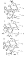
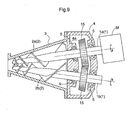
- the two-shaft extruder includes such components as a pair of rotor shafts 1 rotatably disposed with a distance therebetween diminishing toward the leading ends thereof, a pair of screw blades 2 mounted to the respective leading ends of the pair of rotor shafts 1, a pair of motors M with reduction mechanism provided at the respective base ends of the pair of rotor shafts 1 as a pair of drive units for rotatably driving the rotor shafts 1 respectively, and so on.
- Each rotor shaft 1 has an approximately cylindrical shape with a tapered leading end.
- the screw blade 2 is configured as a variable pitch type having its pitch width P progressively decreasing toward the leading end and its flight height reducing toward the same.
- the other screw blade 2b intrudes into the pitch P of one screw blade 2a and the one screw blade 2a intrudes into the pitch P of the other screw blade 2b so that the peripheral edge of the screw blade 2 is disposed in close vicinity of the outer peripheral face of the rotor shaft 1.
- a housing 3 is provided for accommodating therein the rotor shafts 1 and the screw blades 2. And, an amount of high-viscous substance or material can be charged from above the housing 3.
- the base ends of the rotor shafts 1 extend through the extruder main body 4 and bearings 5 are provided between base ends of the rotor shafts 1 and the extruder main body 4, so that the extruder main body 4 rotatably supports the rotor shafts 1. And, at positions offset toward the base ends from the center portions of the rotor shafts 1, there are mounted a first abutment member 6 and a second abutment member 7 to be described later.
- the first abutment member 6 and the second abutment member 7 are provided in an inner space 4a of the extruder main body 4.
- the first abutment member 6 is constituted of a plurality of projecting portions 6a formed on one rotor shaft 1a equidistantly in the peripheral direction.
- the second abutment member 7 is constituted of a plurality of projecting portions 7a formed on the other rotor shaft 1b equidistantly in the peripheral direction. And, arrangement is provided such that the path of the projecting portions 6a of the first abutment member 6 and the path of the projecting portions 7a of the second abutment member 7 interfere with each other.
- a gap (d) for allowing a predetermined phase difference between the pair of rotor shafts 1, while preventing any phase difference greater than the predetermined phase difference.
- a screw blade contact preventing mechanism SS for allowing a predetermined phase difference between the pair of rotor shafts 1, while preventing any phase difference greater than the predetermined phase difference, when the pair of rotor shafts 1 are rotatably driven respectively.
- the first abutment member 6 comprises four projecting portions 6a formed peripherally equidistantly on a cylindrical boss portion 6b attached to the one rotor shaft 1a, each projecting portion 6a having a rectangular plate-like shape with one corner removed therefrom.
- the second abutment member 7 comprises four projecting portions 7a formed peripherally equidistantly on a cylindrical boss portion 7b attached to the other rotor shaft 1b, each projecting portion 7a having a rectangular plate-like shape with one corner removed therefrom.
- distances P1, P2 longitudinally of the respective rotor shaft 1 between the one screw blade 2a and the other screw blade 2b intruding into the pitch P of the one screw blade 2a will vary, thereby to provide an enhanced kneading effect for providing enhanced kneading of an amount of high-viscous substance entrapped between these screw blades 2 and the cleaning effect of the peripheral edge of the screw blade 2 moving along the outer peripheral face of the rotor shaft 1 to remove or scrape off an amount of high-viscous substance adhering to this rotor shaft 1.
- the predetermined phase difference between the pair of rotor shafts 1 is not limited to the 60 degrees phase difference described above, but may vary as desired and/or appropriately, in accordance with such factors as the torsion angle, the flight height of the screw blade 2.
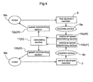
- the construction includes an unillustrated command switch as a phase difference generating commanding means for issuing a phase difference generating command, one proximity sensor 9a disposed in close proximity of the projecting portion 6a of the first abutment member 6, one rotational speed determining section 10a for determining a rotational speed of the first abutment member 6 based on detection information from the proximity sensor 9a and an unillustrated timer, the other proximity sensor 9b disposed in close proximity of the projecting portion 7a of the second abutment member 7, the other rotational speed determining section 10b for determining a rotational speed of the second abutment member 7 based on detection information from the proximity sensor 9b and an unillustrated timer.
- an unillustrated command switch as a phase difference generating commanding means for issuing a phase difference generating command
- one proximity sensor 9a disposed in close proximity of the projecting portion 6a of the first abutment member 6
- one rotational speed determining section 10a for determining a rotational speed of
- the construction further includes a calculating section 11 for calculating a cycle ratio Ta/Tb between a cycle Ta of the first abutment member 6 and a cycle Tb of the second abutment member 7, based on the rotational speeds of the first and second abutment members 6, 7 detected by the rotational speed determining sections 10a, 10b, respectively, one speed commanding section 12a for issuing, to one motor Ma, a speed increasing/decreasing command for increasing/decreasing the rotational speed of this one motor Ma based on the cycle ratio Ta/Tb calculated by the calculating section 11, and the other speed commanding section 12b for issuing, to the other motor Mb, a speed increasing/decreasing command for increasing/decreasing the rotational speed of this other motor Mb based on the cycle ratio Ta/Tb calculated by the calculating section 11.
- the proximity sensors 9a, 9b and the rotational speed determining sections 10a, 10b together constitute "a rotational speed detecting means" for detecting rotational speeds of the first abutment member 6 and the second abutment member 7.
- the rotational speed determining sections 10a, 10b, the calculating section 11, and the speed commanding sections 12a, 12b together constitute a controlling apparatus H as "a controlling means” for controlling drives of the pair of motors M respectively, based on the detection information from the proximity sensors 9a, 9b.
- the controlling apparatus H calculates the cycle ratio Ta/Tb between the cycle Ta of the first abutment member 6 and the cycle Tb of the second abutment member 7 based on the rotational speeds detected by the rotational speed detecting means and also issues a speed increasing/decreasing command to the pair of motors M respectively so that the cycle ratio Ta/Tb may become 1 (one), thereby to execute a synchronization control scheme for driving the pair of motors M respectively.
- the controlling apparatus H issues a speed increasing/decreasing command to the pair of motors M respectively so as to execute a phase difference generating control scheme in such a manner as to generate the predetermined phase difference between the pair of rotor shafts 1, with priority over the synchronization control scheme described above. Therefore, under the normal condition, the pair of motors M are synchronized with each other and as a worker, monitoring the conditions of the rotor shafts 1 and/or the screw blades 2, will operate the commanding switch to issue the phase difference generating command, so that an enhanced kneading effect and/or cleaning effect can be provided as needed or desired.
- the first abutment member 6 will be rotated by 1/4 rotation and the one proximity sensor 9a detects the cycle (0.25 Ta) of the first abutment member 6.
- the second abutment member 7 is rotated by 1/4 rotation and the other proximity sensor 9b detects the cycle (0.25 Tb) of the second abutment member 7.
- the controlling apparatus will calculate the cycle ratio Ta/Tb between the cycle (0.25Ta) in the case of the 1/4 rotation of the first abutment member 6 and the cycle (0.25 Tb) in the case of the 1/4 rotation of the second abutment member 7.
- this cycle ratio Ta/Tb is smaller than 1, that is, the phase of the first abutment member 6 has advanced at the time of the 1/4 rotations of the first abutment member 6 and the second abutment member 7, speed increasing/decreasing commands will be issued respectively to the pair of motors M so that the cycle ratio Ta/Tb between the cycle (0.5Ta) at the time of 1/2 rotation of the first abutment member 6 and the cycle (0.5Tb) at the time of 1/2 rotation of the second abutment member 7 may become 1 (one).
- the speed increasing/decreasing commands are issued to the respective motors M so as to generate the predetermined phase difference between the pair of rotor shafts 1.
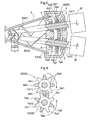
- FIG. 5 and FIG. 6 two sets of the first abutment members 6 and the second abutment members 7 are provided along the longitudinal direction of each rotor shaft 1 (that is, the direction along the bisector dividing the internal angle formed between the pair of rotor shafts 1 into two equal angles). And, the positions of projecting portions 6a1 of the first abutment member 6 belonging to the base end side set (outline portions in FIG.
- the first abutment member 6 belonging to the base end side set comprise four trapezoidal-shaped projecting portions 6a1 peripherally equidistantly disposed on a cylindrical boss portion 6b1 mounted on the one rotor shaft 1a.
- the first abutment member 6 belonging to leading end side set comprise four trapezoidal-shaped projecting portions 6a2 peripherally equidistantly disposed on a cylindrical boss portion 6b2 mounted on the one rotor shaft 1a.
- the second abutment member 7 belonging to the base end side set comprise four trapezoidal-shaped projecting portions 7a1 peripherally equidistantly disposed on a cylindrical boss portion 7b1 mounted on the other rotor shaft 1b.
- the second abutment member 7 belonging to the leading end side set comprise four trapezoidal-shaped projecting portions 7a2 peripherally equidistantly disposed on a cylindrical boss portion 7b2 mounted on the other rotor shaft 1b.
- the first abutment member 6 belonging to the base end side set and the first abutment member 6 belong to the leading end side set are disposed with a phase difference of 45 degrees between these first abutment members 6 as seen along the axial direction of the one rotor shaft.
- the second abutment member 7 belonging to the base end side set and the second abutment member 7 belong to the leading end side set are disposed with a phase difference of 45 degrees between these second abutment members 7 as seen along the axial direction of the other rotor shaft.
- the phase difference to be provided between the first abutment members 6 or between the second abutment members 7 is not limited to the 45 degree phase difference described above. However, such angle (45 degrees) is preferred in view of reliably preventing a phase difference (e.g. about 60 degrees) greater than the predetermined phase difference between the pair of rotor shafts.
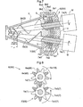
- FIG. 7 and FIG. 8 three sets of the first abutment members 6 and the second abutment members 7 are provided along the longitudinal direction of each rotor shaft 1. And, the positions of projecting portions 6a1 of the first abutment member 6 belonging to the base end side set (outline portions in FIG. 8 ) and the positions of projecting portions 6a2 of the first abutment member 6 belonging to the intermediate side set (shaded portions in FIG.
- the positions of projecting portions 7a1 of the second abutment member 7 belonging to the base end side set and the positions of projecting portions 7a2 of the second abutment member 7 belonging to the intermediate side set adjacent to the base end side set and the positions of the projecting portions 7a3 of the second abutment member 7 belonging to the leading end side set adjacent to the intermediate side set are rendered different from each other in the peripheral direction as seen along the axis of the other rotor shaft.
- the first abutment member 6 belonging to the base end side set comprise three trapezoidal-shaped projecting portions 6a1 peripherally equidistantly disposed on a cylindrical boss portion 6b1 mounted on the one rotor shaft 1a.
- the first abutment member 6 belonging to the intermediate side set comprise three trapezoidal-shaped projecting portions 6a2 peripherally equidistantly disposed on a cylindrical boss portion 6b2 mounted on the one rotor shaft 1a.
- the first abutment member 6 belonging to the leading end side set comprise three trapezoidal-shaped projecting portions 6a3 peripherally equidistantly disposed on a cylindrical boss portion 6b3 mounted on the one rotor shaft 1a.
- the second abutment member 7 belonging to the base end side set comprise three trapezoidal-shaped projecting portions 7a1 peripherally equidistantly disposed on a cylindrical boss portion 7b1 mounted on the other rotor shaft 1b.
- the second abutment member 7 belonging to the intermediate side set comprise three trapezoidal-shaped projecting portions 7a2 peripherally equidistantly disposed on a cylindrical boss portion 7b2 mounted on the other rotor shaft 1b.
- the second abutment member 7 belonging to the leading end side set comprise three trapezoidal-shaped projecting portions 7a3 peripherally equidistantly disposed on a cylindrical boss portion 7b3 mounted on the other rotor shaft 1b.
- first abutment member 6 belonging to the base end side set and the first abutment member 6 belong to the intermediate side set and the first abutment member 6 belong to the leading end side set are disposed with a phase difference of 40 degrees between these first abutment members 6 as seen along the axial direction of the one rotor shaft.
- second abutment member 7 belonging to the base end side set and the second abutment member 7 belonging to the intermediate side set and the second abutment member 7 belong to the leading end side set are disposed with a phase difference of 40 degrees between these second abutment members 7 as seen along the axial direction of the other rotor shaft.
- the number of the sets of the first abutment members 6 and the second abutment members 7 is not limited to 2 or 3, but may be more. In such case, an arrangement will be made such that the first abutment member 6 of each one of the plurality of sets is disposed with an offset in phase as seen in the direction of the one rotor shaft axis by an angle obtained by dividing the angle formed between its projecting portions 6a peripherally adjacent each other by the number of the sets of the first abutment members 6.
- the present invention is useful as a two-shaft extruder having simple construction, yet capable of efficient and effective extrusion.
Landscapes
- Engineering & Computer Science (AREA)
- Mechanical Engineering (AREA)
- Extrusion Moulding Of Plastics Or The Like (AREA)
- Processing And Handling Of Plastics And Other Materials For Molding In General (AREA)
- Mixers Of The Rotary Stirring Type (AREA)
Applications Claiming Priority (2)
| Application Number | Priority Date | Filing Date | Title |
|---|---|---|---|
| JP2008100645A JP5027717B2 (ja) | 2008-04-08 | 2008-04-08 | 2軸押出機 |
| PCT/JP2008/071418 WO2009125514A1 (fr) | 2008-04-08 | 2008-11-26 | Extrudeuse à deux arbres |
Publications (3)
| Publication Number | Publication Date |
|---|---|
| EP2269802A1 true EP2269802A1 (fr) | 2011-01-05 |
| EP2269802A4 EP2269802A4 (fr) | 2013-12-18 |
| EP2269802B1 EP2269802B1 (fr) | 2015-08-12 |
Family
ID=41161654
Family Applications (1)
| Application Number | Title | Priority Date | Filing Date |
|---|---|---|---|
| EP08873882.8A Not-in-force EP2269802B1 (fr) | 2008-04-08 | 2008-11-26 | Extrudeuse à deux arbres |
Country Status (6)
| Country | Link |
|---|---|
| US (1) | US8905623B2 (fr) |
| EP (1) | EP2269802B1 (fr) |
| JP (1) | JP5027717B2 (fr) |
| KR (1) | KR101527252B1 (fr) |
| CN (1) | CN101998901B (fr) |
| WO (1) | WO2009125514A1 (fr) |
Cited By (2)
| Publication number | Priority date | Publication date | Assignee | Title |
|---|---|---|---|---|
| IT202000003413A1 (it) * | 2020-02-19 | 2021-08-19 | Sancassiano Spa | Macchina impastatrice |
| WO2021165871A1 (fr) * | 2020-02-20 | 2021-08-26 | Pomini Rubber & Plastics S.R.L. | Appareil et procédé pour mélanger des matériaux élastomères |
Families Citing this family (18)
| Publication number | Priority date | Publication date | Assignee | Title |
|---|---|---|---|---|
| JP5027717B2 (ja) * | 2008-04-08 | 2012-09-19 | 株式会社モリヤマ | 2軸押出機 |
| JP2013146920A (ja) * | 2012-01-19 | 2013-08-01 | Kankyo Create:Kk | 籾殻含有樹脂組成物の製造方法、籾殻含有樹脂組成物、及び成形品 |
| JP2014019168A (ja) * | 2012-07-12 | 2014-02-03 | Nissan Motor Co Ltd | 駆動力配分装置 |
| JP6066183B2 (ja) * | 2013-01-23 | 2017-01-25 | 日本スピンドル製造株式会社 | スクリュー軸の支持部構造 |
| JP5984186B2 (ja) * | 2013-03-07 | 2016-09-06 | 日本スピンドル製造株式会社 | 2軸押出機 |
| CN103878373A (zh) * | 2014-03-25 | 2014-06-25 | 萍乡亘易隆实业有限公司 | 一种基于无机粉末的双螺杆造粒机 |
| JP6202624B2 (ja) * | 2014-06-30 | 2017-09-27 | 日本スピンドル製造株式会社 | 2軸押出機 |
| RU2605910C2 (ru) * | 2015-04-02 | 2016-12-27 | Егор Владимирович Кулигин | Устройство подготовки формовочной смеси для изготовления изделий из композитного материала (варианты) |
| CN106891505B (zh) * | 2017-04-12 | 2018-10-26 | 许梦艳 | 一种双锥可调速螺杆挤出机 |
| TWM551971U (zh) * | 2017-08-24 | 2017-11-21 | 周延儒 | 連續式超臨界發泡及混練押出設備 |
| JP2020001176A (ja) * | 2018-06-25 | 2020-01-09 | 株式会社神戸製鋼所 | スクリュ式押出機 |
| FR3093457A1 (fr) * | 2019-03-06 | 2020-09-11 | Compagnie Generale Des Etablissements Michelin | Machine de Mélangeage et d’Extrusion à Bi-Vis avec Éléments Amovibles |
| FR3093456A1 (fr) | 2019-03-06 | 2020-09-11 | Compagnie Generale Des Etablissements Michelin | Mécanisme de Sortie d’un Mélangeur à Bi-Vis Conique Convergente |
| FR3093458A1 (fr) | 2019-03-06 | 2020-09-11 | Compagnie Generale Des Etablissements Michelin | Machine de Mélangeage et d’Extrusion à Bi-Vis Autonettoyante et Méthode d’Utilisation |
| FR3093459A1 (fr) | 2019-03-06 | 2020-09-11 | Compagnie Generale Des Etablissements Michelin | Gestion de Température des Mélanges de Caoutchouc Sortant un Mélangeur à Bi-Vis Conique Convergente |
| JP2023515338A (ja) * | 2020-02-20 | 2023-04-13 | ポミニ ラバー アンド プラスチック エス アール エル | エラストマー材料の混合装置および方法 |
| RU199031U1 (ru) * | 2020-04-20 | 2020-08-07 | Егор Владимирвич Кулигин | Устройство подготовки формовочной смеси |
| TWI830232B (zh) * | 2022-05-20 | 2024-01-21 | 國立高雄科技大學 | 雙螺桿裁切碳纖維回收料方法與裝置 |
Family Cites Families (63)
| Publication number | Priority date | Publication date | Assignee | Title |
|---|---|---|---|---|
| US617735A (en) * | 1899-01-17 | godfrey | ||
| US363953A (en) * | 1887-05-31 | Georges alexis-godillot | ||
| US970240A (en) * | 1910-05-23 | 1910-09-13 | Chauncey W Kilborn | Pug-mill and stone-separator. |
| US2041619A (en) * | 1935-04-20 | 1936-05-19 | Clarence M Steele | Clay working machine |
| US2466934A (en) * | 1946-01-05 | 1949-04-12 | Charles E Dellenbarger | Extruding machine for plastic material |
| GB1094035A (en) * | 1964-03-23 | 1967-12-06 | Kawasaki Kokuki Kogyo Kabushik | Improvements in or relating to a plastics extruder |
| US3314660A (en) * | 1965-06-11 | 1967-04-18 | Atlantic Res Corp | Mixer |
| US3605188A (en) * | 1969-08-08 | 1971-09-20 | Nrm Corp | Plastic mixer and extruder |
| NL7101060A (fr) * | 1970-02-10 | 1971-08-12 | ||
| BE788327A (fr) * | 1971-09-02 | 1973-01-02 | Wittrock Ludwig | Procede et dispositif pour l'obtention de matieres premieres thermoplastiques ou produits analogues |
| IT975950B (it) * | 1972-12-05 | 1974-08-10 | Benadi A | Dispositivo per il comando delle vi ti di estrusori del tipo a due viti co rotanti particolarmente per resine termoplastiche |
| DE2446420C2 (de) * | 1974-09-28 | 1982-07-15 | Krauss-Maffei AG, 8000 München | Schneckenstrangpresse zum Verarbeiten von Kunststoffen |
| JPS5549134A (en) * | 1978-10-05 | 1980-04-09 | Masao Moriyama | Continuous mixer |
| JPS5551543A (en) * | 1978-10-12 | 1980-04-15 | Toshiba Mach Co Ltd | Conical multi-shaft extruder screw |
| DE3021739A1 (de) * | 1980-06-10 | 1981-12-17 | Textruder Engineering AG, Zug | Verfahren und doppelschnecken-extruder zur verarbeitung von lebens- und futtermitteln |
| AT371058B (de) * | 1980-11-10 | 1983-05-25 | Maplan Masch Tech Anlagen | Doppelschneckenpresse |
| JPS5942619B2 (ja) * | 1981-03-13 | 1984-10-16 | 正夫 森山 | コ−ン型押出機 |
| JPS60154030A (ja) * | 1984-01-23 | 1985-08-13 | Masao Moriyama | コ−ン型押出機 |
| DE3420918C2 (de) * | 1984-06-05 | 1987-04-02 | Johannes Dr. 8640 Kronach Weber | Doppelschneckenextruder |
| JPS61206715A (ja) * | 1985-03-08 | 1986-09-13 | Hitachi Zosen Corp | 粉体圧送用スクリユウフイ−ダ |
| JPS6264505A (ja) * | 1985-09-18 | 1987-03-23 | Keiji Nakajima | 合成樹脂の混合溶融方法及びその装置 |
| DE3545339A1 (de) * | 1985-12-20 | 1987-07-02 | Krupp Koppers Gmbh | Schneckenfoerderer fuer den transport feinzerteilter fester stoffe |
| US4764020A (en) * | 1986-12-12 | 1988-08-16 | Masao Moriyama | Apparatus for mixing and extruding viscous liquids |
| DE3700771C1 (de) * | 1987-01-13 | 1988-05-05 | Weber Johannes | Doppelschneckenextruder |
| DE3920422A1 (de) * | 1989-06-22 | 1991-01-03 | Basf Ag | Mischvorrichtung fuer mehrkomponentenkunststoffe |
| DE3940833C1 (fr) * | 1989-12-11 | 1990-09-27 | Rhodia Ag, 7800 Freiburg, De | |
| CA2049256A1 (fr) * | 1990-08-22 | 1992-02-23 | Masao Moriyama | Machine a extrusion conique et jumelee |
| DE4126390A1 (de) * | 1991-08-09 | 1993-02-11 | Werner & Pfleiderer | Misch- und aufbereitungsvorrichtung mit austragspumpe |
| JP2962625B2 (ja) * | 1992-11-16 | 1999-10-12 | 株式会社神戸製鋼所 | コーン型2軸押出機 |
| US6258302B1 (en) * | 1999-02-10 | 2001-07-10 | Spalding Sports Worldwide, Inc. | Process for producing polybutadiene golf ball cores |
| JPH06154030A (ja) * | 1993-07-06 | 1994-06-03 | Dentaru Kagaku Kk | 抗菌性アパタイトおよびそれを含有する抗菌性樹脂 |
| JP2698037B2 (ja) * | 1993-09-14 | 1998-01-19 | 株式会社神戸製鋼所 | 押出機のバンク量調節装置 |
| JPH07164508A (ja) * | 1993-12-13 | 1995-06-27 | Kobe Steel Ltd | 二軸押出機の駆動伝達装置 |
| KR100355500B1 (ko) * | 1994-01-19 | 2003-02-05 | 더 다우 케미칼 캄파니 | 1축-스크류압출방법및장치 |
| IT1270683B (it) * | 1994-10-27 | 1997-05-07 | Pomini Spa | Apparecchiatura per l'alimentazione continua di macchine di estrusione e/o laminazione con materiale viscoso quale gomma e simile proveniente da macchine a ciclo discontinuo |
| JP2989110B2 (ja) * | 1994-12-26 | 1999-12-13 | 株式会社日本製鋼所 | 2軸噛合型テーパスクリュフィーダにおける投入原料の有無を検出する方法およびその装置 |
| US5628560A (en) * | 1995-05-24 | 1997-05-13 | American Maplan Corporation | Double-screw extruder |
| JPH091631A (ja) * | 1995-06-16 | 1997-01-07 | Kobe Steel Ltd | ローラヘッド押出機のシート幅調整装置 |
| IT1277236B1 (it) * | 1995-11-21 | 1997-11-05 | Pomini Spa | Macchina a due rotori filettati convergenti per l'estruzione di plastomeri, elastomeri e simili |
| IT1279066B1 (it) * | 1995-11-21 | 1997-12-04 | Pomini Spa | Macchina per l'estrusione di polimeri e simili con rotori filettati convergenti azionati ciascuno tramite un proprio motore di |
| JP2871565B2 (ja) * | 1995-12-26 | 1999-03-17 | 株式会社神戸製鋼所 | ローラヘッド押出機とその制御方法 |
| JPH09300433A (ja) * | 1996-05-20 | 1997-11-25 | Kobe Steel Ltd | 押出機用スクリュウ |
| US5782560A (en) * | 1996-06-24 | 1998-07-21 | Kabushiki Kaisha Kobe Seiko Sho | Internal mixer |
| DE29703158U1 (de) * | 1997-02-22 | 1997-05-22 | Rehau Ag + Co, 95111 Rehau | Doppelschneckenextruder |
| DE19741674A1 (de) * | 1997-09-22 | 1999-03-25 | Haake Gmbh Geb | Mischer insbesondere für viskoelastische Materialien |
| JPH11132166A (ja) * | 1997-10-28 | 1999-05-18 | Mitsubishi Heavy Ind Ltd | スクロール型流体機械 |
| JP2000225641A (ja) * | 1998-12-02 | 2000-08-15 | Ikegai Corp | 押出機 |
| JP2000246731A (ja) * | 1999-03-02 | 2000-09-12 | Kobe Steel Ltd | 混練ロータとこれを有する混練機 |
| JP2002144313A (ja) * | 2000-08-30 | 2002-05-21 | Denso Corp | セラミック成形体の押出成形装置 |
| DE10113949A1 (de) * | 2001-03-22 | 2002-09-26 | Krupp Elastomertechnik Gmbh | Vorrichtung zum Sieben von Kautschuk |
| JP2002355879A (ja) * | 2001-05-30 | 2002-12-10 | Toshiba Mach Co Ltd | コニカル形二軸押出機用スクリュおよびそれを用いた押出成形方法 |
| US6609819B2 (en) * | 2001-07-24 | 2003-08-26 | Wenger Mfg | Twin screw extruder with conical non-parallel converging screws |
| WO2005025847A1 (fr) * | 2003-09-12 | 2005-03-24 | New Pressing Technology Di Babbini Maria Teresa E C. S.R.L. | Presse continue permettant d'extraire par pressage une matiere fibreuse |
| JP4064308B2 (ja) * | 2002-07-17 | 2008-03-19 | 鈴鹿エンヂニヤリング株式会社 | ゴム練り機 |
| DE60325788D1 (de) * | 2003-10-28 | 2009-02-26 | Colmec S P A | Vorrichtung zum mischen und zum extrudieren von kunststoffmaterialien auf kautschukbasis und auf siliconbasis und deren herstellungsverfahren |
| DE10359774A1 (de) | 2003-12-19 | 2005-07-14 | Thyssenkrupp Elastomertechnik Gmbh | Vorrichtung |
| DE102004012569A1 (de) * | 2004-03-12 | 2005-09-29 | A. Friedr. Flender Ag | Getriebe für einen Doppelschneckenextruder |
| JP4255873B2 (ja) * | 2004-03-30 | 2009-04-15 | 株式会社神戸製鋼所 | コニカル二軸押出機及び脱水装置 |
| AT503371B1 (de) * | 2005-11-25 | 2010-11-15 | Schulz Helmuth Ing | Vorrichtung und verfahren zur verarbeitung von material durch mischung und bzw. oder plastifizierung oder agglomerierung |
| US20070190198A1 (en) * | 2006-02-16 | 2007-08-16 | Hyundai Mobis Co., Ltd. | Apparatus for processing polypropylene compound containing glass bubble |
| JP5027717B2 (ja) * | 2008-04-08 | 2012-09-19 | 株式会社モリヤマ | 2軸押出機 |
| JP5102168B2 (ja) * | 2008-10-01 | 2012-12-19 | 株式会社モリヤマ | シート成形装置のトラブル解消方法及びシート成形装置 |
| US8328993B2 (en) * | 2009-05-18 | 2012-12-11 | Greenlight Energy Solutions, Llc | Pyrolysis reactor for processing municipal wastes |
-
2008
- 2008-04-08 JP JP2008100645A patent/JP5027717B2/ja active Active
- 2008-11-26 CN CN2008801284959A patent/CN101998901B/zh not_active Expired - Fee Related
- 2008-11-26 WO PCT/JP2008/071418 patent/WO2009125514A1/fr not_active Ceased
- 2008-11-26 EP EP08873882.8A patent/EP2269802B1/fr not_active Not-in-force
- 2008-11-26 US US12/933,937 patent/US8905623B2/en not_active Expired - Fee Related
- 2008-11-26 KR KR1020107024745A patent/KR101527252B1/ko not_active Expired - Fee Related
Cited By (3)
| Publication number | Priority date | Publication date | Assignee | Title |
|---|---|---|---|---|
| IT202000003413A1 (it) * | 2020-02-19 | 2021-08-19 | Sancassiano Spa | Macchina impastatrice |
| EP3868209A1 (fr) * | 2020-02-19 | 2021-08-25 | SANCASSIANO S.p.A. | Machine à pétrir et procédé de production de pâte |
| WO2021165871A1 (fr) * | 2020-02-20 | 2021-08-26 | Pomini Rubber & Plastics S.R.L. | Appareil et procédé pour mélanger des matériaux élastomères |
Also Published As
| Publication number | Publication date |
|---|---|
| US20110091596A1 (en) | 2011-04-21 |
| KR20110002856A (ko) | 2011-01-10 |
| WO2009125514A1 (fr) | 2009-10-15 |
| CN101998901A (zh) | 2011-03-30 |
| KR101527252B1 (ko) | 2015-06-16 |
| US8905623B2 (en) | 2014-12-09 |
| CN101998901B (zh) | 2013-10-02 |
| EP2269802B1 (fr) | 2015-08-12 |
| JP5027717B2 (ja) | 2012-09-19 |
| EP2269802A4 (fr) | 2013-12-18 |
| JP2009248486A (ja) | 2009-10-29 |
Similar Documents
| Publication | Publication Date | Title |
|---|---|---|
| EP2269802A1 (fr) | Extrudeuse à deux arbres | |
| US8500414B2 (en) | Method of controlling a gear pump as well as an application of the method | |
| KR101622806B1 (ko) | 커터 장치 | |
| EP2286975B1 (fr) | Dispositif de formation de feuilles | |
| JPH02263609A (ja) | 連続混練機の混練制御装置 | |
| US7587975B2 (en) | Embossed sheet forming apparatus and rotary phase difference control method | |
| US20100154610A1 (en) | Cut off apparatus for cutting off corrugated fiberboard web | |
| US20100322806A1 (en) | Arrangement including a gear pump | |
| EP3973185B1 (fr) | Pompe à cavité progressive | |
| AU764062B2 (en) | Displacement machine for compressible media | |
| JP5081013B2 (ja) | 二軸混練押出機及び二軸混練押出機での負荷トルク算出方法 | |
| EP2628391B1 (fr) | Procédé de remplissage de saucisses avec une masse pâteuse et machine de remplissage destinée à l'exécution de ce procédé | |
| JP2007500092A (ja) | 材料処理設備 | |
| JP2010006474A (ja) | 包装装置およびモータ制御装置 | |
| JP4665434B2 (ja) | 歯車機構の潤滑装置 | |
| EP2495626A1 (fr) | Procédé de contrôle de commande électrique d'une machine de fabrication automatique et machine de fabrication automatique à contrôle de commande électrique | |
| CN210025896U (zh) | 开放式炼胶机气动翻炼装置 | |
| JP3611347B2 (ja) | 2軸押出機の内部状態計測方法および装置 | |
| KR20190073148A (ko) | 이중 분할 헬리컬 기어가 구비된 커터 모듈 | |
| KR101167471B1 (ko) | 압연기용 모터의 피엘지 연결장치 | |
| JP2601645B2 (ja) | 連続混練機の混練制御装置 | |
| JP2015157610A (ja) | 電動パワーステアリング装置 | |
| KR20110130684A (ko) | 페어크로스의 이송량 측정장치 | |
| JPS6084474A (ja) | ウオ−ム歯車装置 | |
| JP2008075759A (ja) | 接続装置と、接続装置を介して混練装置と駆動装置とを接続した混練設備 |
Legal Events
| Date | Code | Title | Description |
|---|---|---|---|
| PUAI | Public reference made under article 153(3) epc to a published international application that has entered the european phase |
Free format text: ORIGINAL CODE: 0009012 |
|
| 17P | Request for examination filed |
Effective date: 20101019 |
|
| AK | Designated contracting states |
Kind code of ref document: A1 Designated state(s): AT BE BG CH CY CZ DE DK EE ES FI FR GB GR HR HU IE IS IT LI LT LU LV MC MT NL NO PL PT RO SE SI SK TR |
|
| AX | Request for extension of the european patent |
Extension state: AL BA MK RS |
|
| DAX | Request for extension of the european patent (deleted) | ||
| A4 | Supplementary search report drawn up and despatched |
Effective date: 20131119 |
|
| RIC1 | Information provided on ipc code assigned before grant |
Ipc: B29C 47/40 20060101AFI20131113BHEP Ipc: B29C 47/92 20060101ALI20131113BHEP Ipc: B29C 47/08 20060101ALI20131113BHEP |
|
| 17Q | First examination report despatched |
Effective date: 20140709 |
|
| GRAP | Despatch of communication of intention to grant a patent |
Free format text: ORIGINAL CODE: EPIDOSNIGR1 |
|
| INTG | Intention to grant announced |
Effective date: 20150331 |
|
| RAP1 | Party data changed (applicant data changed or rights of an application transferred) |
Owner name: MORIYAMA COMPANY LTD. |
|
| GRAS | Grant fee paid |
Free format text: ORIGINAL CODE: EPIDOSNIGR3 |
|
| GRAA | (expected) grant |
Free format text: ORIGINAL CODE: 0009210 |
|
| AK | Designated contracting states |
Kind code of ref document: B1 Designated state(s): AT BE BG CH CY CZ DE DK EE ES FI FR GB GR HR HU IE IS IT LI LT LU LV MC MT NL NO PL PT RO SE SI SK TR |
|
| REG | Reference to a national code |
Ref country code: GB Ref legal event code: FG4D |
|
| REG | Reference to a national code |
Ref country code: CH Ref legal event code: EP |
|
| REG | Reference to a national code |
Ref country code: AT Ref legal event code: REF Ref document number: 741736 Country of ref document: AT Kind code of ref document: T Effective date: 20150815 |
|
| REG | Reference to a national code |
Ref country code: IE Ref legal event code: FG4D |
|
| REG | Reference to a national code |
Ref country code: DE Ref legal event code: R096 Ref document number: 602008039595 Country of ref document: DE |
|
| REG | Reference to a national code |
Ref country code: LT Ref legal event code: MG4D |
|
| REG | Reference to a national code |
Ref country code: AT Ref legal event code: MK05 Ref document number: 741736 Country of ref document: AT Kind code of ref document: T Effective date: 20150812 |
|
| REG | Reference to a national code |
Ref country code: NL Ref legal event code: MP Effective date: 20150812 |
|
| PG25 | Lapsed in a contracting state [announced via postgrant information from national office to epo] |
Ref country code: LT Free format text: LAPSE BECAUSE OF FAILURE TO SUBMIT A TRANSLATION OF THE DESCRIPTION OR TO PAY THE FEE WITHIN THE PRESCRIBED TIME-LIMIT Effective date: 20150812 Ref country code: GR Free format text: LAPSE BECAUSE OF FAILURE TO SUBMIT A TRANSLATION OF THE DESCRIPTION OR TO PAY THE FEE WITHIN THE PRESCRIBED TIME-LIMIT Effective date: 20151113 Ref country code: LV Free format text: LAPSE BECAUSE OF FAILURE TO SUBMIT A TRANSLATION OF THE DESCRIPTION OR TO PAY THE FEE WITHIN THE PRESCRIBED TIME-LIMIT Effective date: 20150812 Ref country code: NO Free format text: LAPSE BECAUSE OF FAILURE TO SUBMIT A TRANSLATION OF THE DESCRIPTION OR TO PAY THE FEE WITHIN THE PRESCRIBED TIME-LIMIT Effective date: 20151112 Ref country code: FI Free format text: LAPSE BECAUSE OF FAILURE TO SUBMIT A TRANSLATION OF THE DESCRIPTION OR TO PAY THE FEE WITHIN THE PRESCRIBED TIME-LIMIT Effective date: 20150812 |
|
| PG25 | Lapsed in a contracting state [announced via postgrant information from national office to epo] |
Ref country code: PT Free format text: LAPSE BECAUSE OF FAILURE TO SUBMIT A TRANSLATION OF THE DESCRIPTION OR TO PAY THE FEE WITHIN THE PRESCRIBED TIME-LIMIT Effective date: 20151214 Ref country code: ES Free format text: LAPSE BECAUSE OF FAILURE TO SUBMIT A TRANSLATION OF THE DESCRIPTION OR TO PAY THE FEE WITHIN THE PRESCRIBED TIME-LIMIT Effective date: 20150812 Ref country code: IS Free format text: LAPSE BECAUSE OF FAILURE TO SUBMIT A TRANSLATION OF THE DESCRIPTION OR TO PAY THE FEE WITHIN THE PRESCRIBED TIME-LIMIT Effective date: 20151212 Ref country code: HR Free format text: LAPSE BECAUSE OF FAILURE TO SUBMIT A TRANSLATION OF THE DESCRIPTION OR TO PAY THE FEE WITHIN THE PRESCRIBED TIME-LIMIT Effective date: 20150812 Ref country code: AT Free format text: LAPSE BECAUSE OF FAILURE TO SUBMIT A TRANSLATION OF THE DESCRIPTION OR TO PAY THE FEE WITHIN THE PRESCRIBED TIME-LIMIT Effective date: 20150812 Ref country code: SE Free format text: LAPSE BECAUSE OF FAILURE TO SUBMIT A TRANSLATION OF THE DESCRIPTION OR TO PAY THE FEE WITHIN THE PRESCRIBED TIME-LIMIT Effective date: 20150812 Ref country code: PL Free format text: LAPSE BECAUSE OF FAILURE TO SUBMIT A TRANSLATION OF THE DESCRIPTION OR TO PAY THE FEE WITHIN THE PRESCRIBED TIME-LIMIT Effective date: 20150812 |
|
| PG25 | Lapsed in a contracting state [announced via postgrant information from national office to epo] |
Ref country code: NL Free format text: LAPSE BECAUSE OF FAILURE TO SUBMIT A TRANSLATION OF THE DESCRIPTION OR TO PAY THE FEE WITHIN THE PRESCRIBED TIME-LIMIT Effective date: 20150812 |
|
| PG25 | Lapsed in a contracting state [announced via postgrant information from national office to epo] |
Ref country code: CZ Free format text: LAPSE BECAUSE OF FAILURE TO SUBMIT A TRANSLATION OF THE DESCRIPTION OR TO PAY THE FEE WITHIN THE PRESCRIBED TIME-LIMIT Effective date: 20150812 Ref country code: SK Free format text: LAPSE BECAUSE OF FAILURE TO SUBMIT A TRANSLATION OF THE DESCRIPTION OR TO PAY THE FEE WITHIN THE PRESCRIBED TIME-LIMIT Effective date: 20150812 Ref country code: DK Free format text: LAPSE BECAUSE OF FAILURE TO SUBMIT A TRANSLATION OF THE DESCRIPTION OR TO PAY THE FEE WITHIN THE PRESCRIBED TIME-LIMIT Effective date: 20150812 Ref country code: EE Free format text: LAPSE BECAUSE OF FAILURE TO SUBMIT A TRANSLATION OF THE DESCRIPTION OR TO PAY THE FEE WITHIN THE PRESCRIBED TIME-LIMIT Effective date: 20150812 |
|
| REG | Reference to a national code |
Ref country code: DE Ref legal event code: R097 Ref document number: 602008039595 Country of ref document: DE |
|
| PG25 | Lapsed in a contracting state [announced via postgrant information from national office to epo] |
Ref country code: RO Free format text: LAPSE BECAUSE OF FAILURE TO SUBMIT A TRANSLATION OF THE DESCRIPTION OR TO PAY THE FEE WITHIN THE PRESCRIBED TIME-LIMIT Effective date: 20150812 |
|
| PLBE | No opposition filed within time limit |
Free format text: ORIGINAL CODE: 0009261 |
|
| STAA | Information on the status of an ep patent application or granted ep patent |
Free format text: STATUS: NO OPPOSITION FILED WITHIN TIME LIMIT |
|
| PG25 | Lapsed in a contracting state [announced via postgrant information from national office to epo] |
Ref country code: LU Free format text: LAPSE BECAUSE OF FAILURE TO SUBMIT A TRANSLATION OF THE DESCRIPTION OR TO PAY THE FEE WITHIN THE PRESCRIBED TIME-LIMIT Effective date: 20151126 Ref country code: MC Free format text: LAPSE BECAUSE OF FAILURE TO SUBMIT A TRANSLATION OF THE DESCRIPTION OR TO PAY THE FEE WITHIN THE PRESCRIBED TIME-LIMIT Effective date: 20150812 |
|
| REG | Reference to a national code |
Ref country code: CH Ref legal event code: PL |
|
| 26N | No opposition filed |
Effective date: 20160513 |
|
| PG25 | Lapsed in a contracting state [announced via postgrant information from national office to epo] |
Ref country code: CH Free format text: LAPSE BECAUSE OF NON-PAYMENT OF DUE FEES Effective date: 20151130 Ref country code: LI Free format text: LAPSE BECAUSE OF NON-PAYMENT OF DUE FEES Effective date: 20151130 |
|
| REG | Reference to a national code |
Ref country code: IE Ref legal event code: MM4A |
|
| REG | Reference to a national code |
Ref country code: FR Ref legal event code: ST Effective date: 20160729 |
|
| PG25 | Lapsed in a contracting state [announced via postgrant information from national office to epo] |
Ref country code: SI Free format text: LAPSE BECAUSE OF FAILURE TO SUBMIT A TRANSLATION OF THE DESCRIPTION OR TO PAY THE FEE WITHIN THE PRESCRIBED TIME-LIMIT Effective date: 20150812 |
|
| PG25 | Lapsed in a contracting state [announced via postgrant information from national office to epo] |
Ref country code: IE Free format text: LAPSE BECAUSE OF NON-PAYMENT OF DUE FEES Effective date: 20151126 |
|
| PG25 | Lapsed in a contracting state [announced via postgrant information from national office to epo] |
Ref country code: FR Free format text: LAPSE BECAUSE OF NON-PAYMENT OF DUE FEES Effective date: 20151130 |
|
| PG25 | Lapsed in a contracting state [announced via postgrant information from national office to epo] |
Ref country code: BE Free format text: LAPSE BECAUSE OF FAILURE TO SUBMIT A TRANSLATION OF THE DESCRIPTION OR TO PAY THE FEE WITHIN THE PRESCRIBED TIME-LIMIT Effective date: 20150812 |
|
| PG25 | Lapsed in a contracting state [announced via postgrant information from national office to epo] |
Ref country code: BG Free format text: LAPSE BECAUSE OF FAILURE TO SUBMIT A TRANSLATION OF THE DESCRIPTION OR TO PAY THE FEE WITHIN THE PRESCRIBED TIME-LIMIT Effective date: 20150812 Ref country code: HU Free format text: LAPSE BECAUSE OF FAILURE TO SUBMIT A TRANSLATION OF THE DESCRIPTION OR TO PAY THE FEE WITHIN THE PRESCRIBED TIME-LIMIT; INVALID AB INITIO Effective date: 20081126 |
|
| PG25 | Lapsed in a contracting state [announced via postgrant information from national office to epo] |
Ref country code: CY Free format text: LAPSE BECAUSE OF FAILURE TO SUBMIT A TRANSLATION OF THE DESCRIPTION OR TO PAY THE FEE WITHIN THE PRESCRIBED TIME-LIMIT Effective date: 20150812 |
|
| PG25 | Lapsed in a contracting state [announced via postgrant information from national office to epo] |
Ref country code: MT Free format text: LAPSE BECAUSE OF FAILURE TO SUBMIT A TRANSLATION OF THE DESCRIPTION OR TO PAY THE FEE WITHIN THE PRESCRIBED TIME-LIMIT Effective date: 20150812 Ref country code: TR Free format text: LAPSE BECAUSE OF FAILURE TO SUBMIT A TRANSLATION OF THE DESCRIPTION OR TO PAY THE FEE WITHIN THE PRESCRIBED TIME-LIMIT Effective date: 20150812 |
|
| REG | Reference to a national code |
Ref country code: DE Ref legal event code: R079 Ref document number: 602008039595 Country of ref document: DE Free format text: PREVIOUS MAIN CLASS: B29C0047400000 Ipc: B29C0048400000 |
|
| PGFP | Annual fee paid to national office [announced via postgrant information from national office to epo] |
Ref country code: GB Payment date: 20181121 Year of fee payment: 11 Ref country code: IT Payment date: 20181122 Year of fee payment: 11 |
|
| GBPC | Gb: european patent ceased through non-payment of renewal fee |
Effective date: 20191126 |
|
| PG25 | Lapsed in a contracting state [announced via postgrant information from national office to epo] |
Ref country code: IT Free format text: LAPSE BECAUSE OF NON-PAYMENT OF DUE FEES Effective date: 20191126 Ref country code: GB Free format text: LAPSE BECAUSE OF NON-PAYMENT OF DUE FEES Effective date: 20191126 |
|
| PGFP | Annual fee paid to national office [announced via postgrant information from national office to epo] |
Ref country code: DE Payment date: 20211005 Year of fee payment: 14 |
|
| REG | Reference to a national code |
Ref country code: DE Ref legal event code: R119 Ref document number: 602008039595 Country of ref document: DE |
|
| PG25 | Lapsed in a contracting state [announced via postgrant information from national office to epo] |
Ref country code: DE Free format text: LAPSE BECAUSE OF NON-PAYMENT OF DUE FEES Effective date: 20230601 |