EP3875396A1 - Faisceau d'articles en verre tubulaire et/ou en forme de tige, son procédé de fabrication ainsi que pour le déballage dudit faisceau - Google Patents
Faisceau d'articles en verre tubulaire et/ou en forme de tige, son procédé de fabrication ainsi que pour le déballage dudit faisceau Download PDFInfo
- Publication number
- EP3875396A1 EP3875396A1 EP21160015.0A EP21160015A EP3875396A1 EP 3875396 A1 EP3875396 A1 EP 3875396A1 EP 21160015 A EP21160015 A EP 21160015A EP 3875396 A1 EP3875396 A1 EP 3875396A1
- Authority
- EP
- European Patent Office
- Prior art keywords
- thread
- tubular
- rod
- bundle
- glass articles
- Prior art date
- Legal status (The legal status is an assumption and is not a legal conclusion. Google has not performed a legal analysis and makes no representation as to the accuracy of the status listed.)
- Withdrawn
Links
Images





Classifications
-
- B—PERFORMING OPERATIONS; TRANSPORTING
- B65—CONVEYING; PACKING; STORING; HANDLING THIN OR FILAMENTARY MATERIAL
- B65D—CONTAINERS FOR STORAGE OR TRANSPORT OF ARTICLES OR MATERIALS, e.g. BAGS, BARRELS, BOTTLES, BOXES, CANS, CARTONS, CRATES, DRUMS, JARS, TANKS, HOPPERS, FORWARDING CONTAINERS; ACCESSORIES, CLOSURES, OR FITTINGS THEREFOR; PACKAGING ELEMENTS; PACKAGES
- B65D63/00—Flexible elongated elements, e.g. straps, for bundling or supporting articles
-
- B—PERFORMING OPERATIONS; TRANSPORTING
- B65—CONVEYING; PACKING; STORING; HANDLING THIN OR FILAMENTARY MATERIAL
- B65D—CONTAINERS FOR STORAGE OR TRANSPORT OF ARTICLES OR MATERIALS, e.g. BAGS, BARRELS, BOTTLES, BOXES, CANS, CARTONS, CRATES, DRUMS, JARS, TANKS, HOPPERS, FORWARDING CONTAINERS; ACCESSORIES, CLOSURES, OR FITTINGS THEREFOR; PACKAGING ELEMENTS; PACKAGES
- B65D75/00—Packages comprising articles or materials partially or wholly enclosed in strips, sheets, blanks, tubes or webs of flexible sheet material, e.g. in folded wrappers
- B65D75/002—Packages comprising articles or materials partially or wholly enclosed in strips, sheets, blanks, tubes or webs of flexible sheet material, e.g. in folded wrappers in shrink films
- B65D75/004—Packages comprising articles or materials partially or wholly enclosed in strips, sheets, blanks, tubes or webs of flexible sheet material, e.g. in folded wrappers in shrink films with auxiliary packaging elements, e.g. protective pads or frames, trays
-
- B—PERFORMING OPERATIONS; TRANSPORTING
- B65—CONVEYING; PACKING; STORING; HANDLING THIN OR FILAMENTARY MATERIAL
- B65D—CONTAINERS FOR STORAGE OR TRANSPORT OF ARTICLES OR MATERIALS, e.g. BAGS, BARRELS, BOTTLES, BOXES, CANS, CARTONS, CRATES, DRUMS, JARS, TANKS, HOPPERS, FORWARDING CONTAINERS; ACCESSORIES, CLOSURES, OR FITTINGS THEREFOR; PACKAGING ELEMENTS; PACKAGES
- B65D63/00—Flexible elongated elements, e.g. straps, for bundling or supporting articles
- B65D63/10—Non-metallic straps, tapes, or bands; Filamentary elements, e.g. strings, threads or wires; Joints between ends thereof
-
- B—PERFORMING OPERATIONS; TRANSPORTING
- B65—CONVEYING; PACKING; STORING; HANDLING THIN OR FILAMENTARY MATERIAL
- B65B—MACHINES, APPARATUS OR DEVICES FOR, OR METHODS OF, PACKAGING ARTICLES OR MATERIALS; UNPACKING
- B65B13/00—Bundling articles
- B65B13/02—Applying and securing binding material around articles or groups of articles, e.g. using strings, wires, strips, bands or tapes
-
- B—PERFORMING OPERATIONS; TRANSPORTING
- B65—CONVEYING; PACKING; STORING; HANDLING THIN OR FILAMENTARY MATERIAL
- B65B—MACHINES, APPARATUS OR DEVICES FOR, OR METHODS OF, PACKAGING ARTICLES OR MATERIALS; UNPACKING
- B65B23/00—Packaging fragile or shock-sensitive articles other than bottles; Unpacking eggs
-
- B—PERFORMING OPERATIONS; TRANSPORTING
- B65—CONVEYING; PACKING; STORING; HANDLING THIN OR FILAMENTARY MATERIAL
- B65B—MACHINES, APPARATUS OR DEVICES FOR, OR METHODS OF, PACKAGING ARTICLES OR MATERIALS; UNPACKING
- B65B27/00—Bundling particular articles presenting special problems using string, wire, or narrow tape or band; Baling fibrous material, e.g. peat, not otherwise provided for
- B65B27/10—Bundling rods, sticks, or like elongated objects
-
- B—PERFORMING OPERATIONS; TRANSPORTING
- B65—CONVEYING; PACKING; STORING; HANDLING THIN OR FILAMENTARY MATERIAL
- B65B—MACHINES, APPARATUS OR DEVICES FOR, OR METHODS OF, PACKAGING ARTICLES OR MATERIALS; UNPACKING
- B65B69/00—Unpacking of articles or materials, not otherwise provided for
- B65B69/0025—Removing or cutting binding material, e.g. straps or bands
-
- B—PERFORMING OPERATIONS; TRANSPORTING
- B65—CONVEYING; PACKING; STORING; HANDLING THIN OR FILAMENTARY MATERIAL
- B65D—CONTAINERS FOR STORAGE OR TRANSPORT OF ARTICLES OR MATERIALS, e.g. BAGS, BARRELS, BOTTLES, BOXES, CANS, CARTONS, CRATES, DRUMS, JARS, TANKS, HOPPERS, FORWARDING CONTAINERS; ACCESSORIES, CLOSURES, OR FITTINGS THEREFOR; PACKAGING ELEMENTS; PACKAGES
- B65D71/00—Bundles of articles held together by packaging elements for convenience of storage or transport, e.g. portable segregating carrier for plural receptacles such as beer cans or pop bottles; Bales of material
- B65D71/0088—Palletisable loads, i.e. loads intended to be transported by means of a fork-lift truck
- B65D71/0092—Palletisable loads, i.e. loads intended to be transported by means of a fork-lift truck provided with one or more rigid supports, at least one dimension of the supports corresponding to a dimension of the load, e.g. skids
-
- B—PERFORMING OPERATIONS; TRANSPORTING
- B65—CONVEYING; PACKING; STORING; HANDLING THIN OR FILAMENTARY MATERIAL
- B65D—CONTAINERS FOR STORAGE OR TRANSPORT OF ARTICLES OR MATERIALS, e.g. BAGS, BARRELS, BOTTLES, BOXES, CANS, CARTONS, CRATES, DRUMS, JARS, TANKS, HOPPERS, FORWARDING CONTAINERS; ACCESSORIES, CLOSURES, OR FITTINGS THEREFOR; PACKAGING ELEMENTS; PACKAGES
- B65D71/00—Bundles of articles held together by packaging elements for convenience of storage or transport, e.g. portable segregating carrier for plural receptacles such as beer cans or pop bottles; Bales of material
- B65D71/02—Arrangements of flexible binders
-
- B—PERFORMING OPERATIONS; TRANSPORTING
- B65—CONVEYING; PACKING; STORING; HANDLING THIN OR FILAMENTARY MATERIAL
- B65D—CONTAINERS FOR STORAGE OR TRANSPORT OF ARTICLES OR MATERIALS, e.g. BAGS, BARRELS, BOTTLES, BOXES, CANS, CARTONS, CRATES, DRUMS, JARS, TANKS, HOPPERS, FORWARDING CONTAINERS; ACCESSORIES, CLOSURES, OR FITTINGS THEREFOR; PACKAGING ELEMENTS; PACKAGES
- B65D81/00—Containers, packaging elements, or packages, for contents presenting particular transport or storage problems, or adapted to be used for non-packaging purposes after removal of contents
- B65D81/02—Containers, packaging elements, or packages, for contents presenting particular transport or storage problems, or adapted to be used for non-packaging purposes after removal of contents specially adapted to protect contents from mechanical damage
- B65D81/05—Containers, packaging elements, or packages, for contents presenting particular transport or storage problems, or adapted to be used for non-packaging purposes after removal of contents specially adapted to protect contents from mechanical damage maintaining contents at spaced relation from package walls, or from other contents
-
- B—PERFORMING OPERATIONS; TRANSPORTING
- B65—CONVEYING; PACKING; STORING; HANDLING THIN OR FILAMENTARY MATERIAL
- B65D—CONTAINERS FOR STORAGE OR TRANSPORT OF ARTICLES OR MATERIALS, e.g. BAGS, BARRELS, BOTTLES, BOXES, CANS, CARTONS, CRATES, DRUMS, JARS, TANKS, HOPPERS, FORWARDING CONTAINERS; ACCESSORIES, CLOSURES, OR FITTINGS THEREFOR; PACKAGING ELEMENTS; PACKAGES
- B65D85/00—Containers, packaging elements or packages, specially adapted for particular articles or materials
- B65D85/20—Containers, packaging elements or packages, specially adapted for particular articles or materials for incompressible or rigid rod-shaped or tubular articles
-
- B—PERFORMING OPERATIONS; TRANSPORTING
- B65—CONVEYING; PACKING; STORING; HANDLING THIN OR FILAMENTARY MATERIAL
- B65D—CONTAINERS FOR STORAGE OR TRANSPORT OF ARTICLES OR MATERIALS, e.g. BAGS, BARRELS, BOTTLES, BOXES, CANS, CARTONS, CRATES, DRUMS, JARS, TANKS, HOPPERS, FORWARDING CONTAINERS; ACCESSORIES, CLOSURES, OR FITTINGS THEREFOR; PACKAGING ELEMENTS; PACKAGES
- B65D85/00—Containers, packaging elements or packages, specially adapted for particular articles or materials
- B65D85/30—Containers, packaging elements or packages, specially adapted for particular articles or materials for articles particularly sensitive to damage by shock or pressure
- B65D85/307—Local shock-absorbing elements, e.g. elastic rings
-
- B—PERFORMING OPERATIONS; TRANSPORTING
- B65—CONVEYING; PACKING; STORING; HANDLING THIN OR FILAMENTARY MATERIAL
- B65D—CONTAINERS FOR STORAGE OR TRANSPORT OF ARTICLES OR MATERIALS, e.g. BAGS, BARRELS, BOTTLES, BOXES, CANS, CARTONS, CRATES, DRUMS, JARS, TANKS, HOPPERS, FORWARDING CONTAINERS; ACCESSORIES, CLOSURES, OR FITTINGS THEREFOR; PACKAGING ELEMENTS; PACKAGES
- B65D85/00—Containers, packaging elements or packages, specially adapted for particular articles or materials
- B65D85/62—Containers, packaging elements or packages, specially adapted for particular articles or materials for stacks of articles; for special arrangements of groups of articles
-
- B—PERFORMING OPERATIONS; TRANSPORTING
- B65—CONVEYING; PACKING; STORING; HANDLING THIN OR FILAMENTARY MATERIAL
- B65B—MACHINES, APPARATUS OR DEVICES FOR, OR METHODS OF, PACKAGING ARTICLES OR MATERIALS; UNPACKING
- B65B19/00—Packaging rod-shaped or tubular articles susceptible to damage by abrasion or pressure, e.g. cigarettes, cigars, macaroni, spaghetti, drinking straws or welding electrodes
- B65B19/34—Packaging other rod-shaped articles, e.g. sausages, macaroni, spaghetti, drinking straws, welding electrodes
-
- B—PERFORMING OPERATIONS; TRANSPORTING
- B65—CONVEYING; PACKING; STORING; HANDLING THIN OR FILAMENTARY MATERIAL
- B65D—CONTAINERS FOR STORAGE OR TRANSPORT OF ARTICLES OR MATERIALS, e.g. BAGS, BARRELS, BOTTLES, BOXES, CANS, CARTONS, CRATES, DRUMS, JARS, TANKS, HOPPERS, FORWARDING CONTAINERS; ACCESSORIES, CLOSURES, OR FITTINGS THEREFOR; PACKAGING ELEMENTS; PACKAGES
- B65D2571/00—Bundles of articles held together by packaging elements for convenience of storage or transport, e.g. portable segregating carrier for plural receptacles such as beer cans, pop bottles; Bales of material
- B65D2571/00123—Bundling wrappers or trays
- B65D2571/00648—Elements used to form the wrapper
- B65D2571/00672—Films
- B65D2571/00679—Shrink films
Definitions
- the present invention relates to a bundle of tubular and/or rod-shaped glass articles, a method for bundling such glass articles, as well as to a method for unpacking such a bundle.
- Tubular and/or rod-shaped glass articles are common half-finished or pre-products used, for example, for pharmaceutical packing, i.e. for the production of glass vials, ampoules, syringes, cartridges or the like, or for glass fibres. Further production processes may take place in specialised production sites. Therefore, after melting and hot forming, tubular and/or rod-shaped glass articles are usually shipped to such further production sites. For an easy and cost efficient shipment, a certain plurality of tubular and/or rod-shaped glass articles are usually combined to a bundle. In such a bundle, the tubular and/or rod-shaped glass articles are usually arranged in a way that, when viewed in a direction along the length of the glass articles, they form a close or dense packing. In order to ensure safe shipment and to prevent relative movement of the glass rods and/or glass tubes, such as scrubbing or rubbing, as far as possible, the bundle may be fixed for example, by using a belt or a heat-shrink tubing.
- German patent application DE 27 29 966 A1 relates to a method for packaging tubes or rods, wherein tubes or rods of equal length are arranged in a close packed bundle, both ends of which are wrapped in a flexible material, like a foil or a film, for example, polymeric or plastic film, in order to fasten the rods or tubes or the bundle, respectively.
- Japanese patent application JP H09-295686 A discloses a glass tube packaging body with a plurality of stages with spacers.
- Patent document DD 82301 relates to a packaging for tubular glass bodies, the packaging comprising corrugated card board.
- Patent document DD 224 555 A1 relates to a heat-shrink tubing for the packaging of glass tubes or glass rods.
- German utility model DE 201 21 582 U1 relates to a packaging for glass tubes. Both ends of the glass tubes are covered by a cap. The glass tubes are then assembled in a bundle, both ends of which are covered by a shrink wrap film.
- European patent application EP 0 132 587 A1 discloses a bundle of tubes.
- the tubes are arranged in stacked layers of tubes. Between each layer, a slip-resistant film is arranged.
- US patent specification US 3 373 540 A discloses a method for bundling elongated articles wherein a tensilely strong supple material is wrapped around the elongated articles at least partially.
- US 3 373 540 A does not teach the use of thread-like elements in combination with tubular and/or rod-shaped glass articles, but lists a variety of tensilely strong supple materials, such as cord, yard, twine, thread, rope, band, ribbon tape and so forth.
- a single line 11 tensilely string supple material is used, that is entwined about and between the articles to be bundles in a rather complicated way.
- line 11 is a rather rigid material with a large cross section. While this large cross section ensures a large enough spacing of the bundled articles, the resulting ladder-like structure is rather inflexible and further results in a rather space-consuming bundle. Furthermore, rather rigid, solid line 11 is not well suited for fixing or fastening of the elongated articles to be bundled but allows for sliding of the articles in the loops formed by line 11 along the length of the bundle.
- German patent specification DE 42 25 876 C2 relates to an apparatus for bundling rid-shaped articles.
- a flexible, foil-like or film-like material is placed between the rod-shaped articles.
- US patent specification US 3 294 225 A relates to a combined shipping package as well as to a protective armour for glass pipes, said armour being an encasement for a single glass pipe Several encased glass pipes may be combined to form a bundle.
- the problem of the present invention is therefore to provide for a bundle of tubular and/or rod-shaped glass articles that show the drawbacks of the state of the art at least only to a lesser degree, if at all. Further, the problem of the present invention is according to further aspects directed towards a method of bundling as and to a method of unpacking of a bundle that overcome the drawbacks of the state of the art at least partially.
- the present disclosure therefore relates to a bundle of tubular and/or rod-shaped glass articles, the longest dimension of the tubular and/or rod-shaped glass articles extending in a first direction of a Cartesian coordinate system, defining a length I of the tubular and/or rod-shaped glass articles, comprising a number N L of layers of the tubular and/or rod-shaped glass articles, the glass articles in each layer being arranged side by side in a second direction of the Cartesian coordinate system perpendicular to the first direction, wherein N L is at least 2, wherein the N L layers of the tubular and/or rod-shaped glass articles are arranged side by side in a third direction of the Cartesian coordinate system, the third direction being perpendicular to the first and second directions, preferably forming a close packing of the tubular and/or rod-shaped glass articles when viewed along the first direction, and at least one thread-like element that is wrapped around at least two tubular and/or rod-shaped articles in at least one of the N L layers of tubular and/or
- the at least one thread-like element may have a cross section between of at least 0.25 mm to at most 2.5 mm, preferably of at least 1.5 mm to at most 2.5 mm, or preferably of at least 0.25 mm to at most 1.25 mm, more preferably to about at most 1.0 mm.
- the at least one thread-like element may have a cross section of 0.1 mm, or of 0.2 mm, or of 0.3 mm, or of 0.4 mm, or of 0.5 mm, or of 0.6 mm, or of 0.7 mm, or of 0.8 mm, or of 0.9 mm, or of 0.95 mm, or of 1.0 mm, or of 1.05 mm, or of 1.1 mm, or of 1.5 mm.
- the three dimensions of the Cartesian coordinate system may also be denoted as x, y, and z directions.
- Such an embodiment of a bundle of rod-shaped and/or tubular glass articles offers several advantages.
- At least two of the glass articles in at least one of the N L layers of glass articles are spaced apart. It is preferred that all glass articles in a layer, preferably in all layers (and so, all tubular and/or rod-shaped glass articles comprised by the bundle), are spaced apart, in order to prevent surface defects caused by relative movement of the tubular and/or rod-shaped glass articles in the bundle during handling and/or shipping of the bundle.
- This is advantageous, as in this way there will be less deficient tubular and/or rod-shaped articles that cannot be used in subsequent production processes. Further, as scratching is reduced, particle contamination of the tubular and/or rod-shaped glass articles will be lower compared to standard packaging methods without spacers. Therefore, it is advantageous to use glass articles spaced apart by a thread-like element for the production of pharmaceutical packaging products, like glass vials, ampoules, cartridges, syringes or the like.
- arranging glass articles, like glass tubes and glass rods, in a layer-wise manner offers the advantage to closely pack these articles, while lessening the risk of tilting and twisting these articles, for example during rolling of a ladder-like structure as in US 3 373 540 A .
- a further advantage of a layer-like arrangement of tubular and/or rod-shaped in a bundle is that in this way a bundle may more easily be packed and unpacked, as this layer-wise arrangement allows piling or stacking of the layers.
- this layer-wise arrangement allows piling or stacking of the layers.
- twisting and tilting of the glass articles may in a very easy manner be avoided or at least minimized.
- thread-like elements like threads, yarn, twine, strings or the like, are quite commonly known materials, therefore available in a huge variety of materials, quality and quantity and at comparably low cost.
- the thread-like element according to the present disclosure may have a cross section (or diameter, or outer dimension) of at most 4.0 mm, or even of at most 2.5 mm, meaning that, especially when compared with ribbons, or cardboard or paper layers or other means for spacing apart that have been used in the state of the art, only a very small quantity of material is necessary. Therefore, using a thread-like element as spacer in a bundle of rod-shaped and/or tubular glass articles is not only advantageous in terms of cost and material availability, but also in terms of environmental sustainability.
- the cross section of the thread-like element may at least be of 0.25 mm, preferably of at least 0.5 mm or even more than 0.5 mm.
- the cross section of the at least one thread-like element is between at least 0.25 mm to at most 2.5 mm. According to another embodiment, the cross section of the at least one thread-like element is between at least 1.5 mm to at most 2.5 mm. According to a further embodiment, the cross section is between at least 0.25 mm to at most 1.25 mm. According to a further embodiment, the cross section is between at least 0.25 mm to about at most 1.0 mm.
- the cross section of the thread-like element may be determined in accordance with and/or on the basis of the projection microscope method as described, for example, in DIN EN ISO 137.
- the at least one thread-like element is fastened or tied, thereby forming at least one knot, preferably by forming at least one loop or bight, such as a loop knot.
- a knot such as a loop knot, with an adhesive force, preferably a maximum adhesive force, between about 0.1 N and 4.0 N, preferably between 0.4 N and 3.5 N is formed.
- several knots for example corresponding to the number of tubular and/or rod-shaped articles bundled or arranged within a layer of the bundle, or to a multiple of this number, may be formed.
- several knots are formed in a like manner, so that all knots formed correspond to the same knot type.
- a knot is understood to refer to any intentional complication to a thread-like element, such as cord or yarn or a thread or any other thread-like element.
- “Complication” in the sense of the disclosure, may be any form of entwining, interlacing, or wrapping of a thread-like element, for example by forming loops or bights or the like.
- Knots may be formed by tying, or else by techniques such as knotting, sewing and stitching, in order to fasten or secure or constrict objects, for example, and may be accomplished by using any kind of suitable means, such as a needle.
- the knot or knots formed are releasable knots, that is, a knot or knots that may easily be untied by pulling. Further preferably, the knot or knots formed are non-jamming knots.
- Adhesive force of a knot is understood to refer to the force between the parts of the thread-like element or thread-like elements, in case the knot is formed by tying of tying several thread-like elements, for example, two thread-like elements, that is, the force holding the different parts of the thread-like element or element together.
- Adhesive force of a knot in the sense of the present disclosure is therefore understood to refer to the force necessary to untie the knot, thereby releasing or unwrapping the thread-like element or the thread-like elements.
- the minimum force necessary for untying the knot for example by pulling the thread-like element (also denoted as "pulling force" in the sense of the disclosure), has the same absolute value than the maximum adhesive force of said knot.
- Adhesive force of a knot in a bundle or layer of tubular and/or rod-shaped articles may be influenced by a normal force acting on both the thread-like element or elem1.6ents and the articles, for example, because of the weight of the glass articles, causing the thread-like elements and the glass articles to be more closely stacked upon each other, thereby increasing the force needed to undue the knot or knots. Therefore, when reference is made to adhesive force of a knot, this preferably refers to the adhesive force of a knot in a top layer or single layer of tubular and/or rod-shaped glass articles.
- the adhesive force preferably the maximum adhesive force of a knot is set between at least 0.1 N and at most 4.0 N. That is, a minimum pulling force, preferably a force acting in an axial direction of the thread-like element, of 0.1 N and at most 4.0 N is necessary to undue the knot.
- Pulling force in the sense of the disclosure, is a force acting on a loose or free end of a thread-like element forming the knots or, in case the knot is formed by more than one thread-like element, of one end of at least one of the thread-like elements forming the knot.
- the pulling force is acting in an axial direction of the thread-like element.
- Minimum pulling force in the sense of the disclosure, is the minimum pulling force needed to untie a knot. It is to be noted here that for knots of the same type, this minimum pulling force still may differ, as may the corresponding maximum adhesive force of the respective knot. Minimum pulling forces as well as maximum adhesive forces may therefore preferably given by indicating a range or an average value. Further, upon pulling a free end of a thread tied to a knot, the force may differ over time corresponding to different stages of the process of untying. It is understood here that the minimum pulling force indicates that force necessary for releasing the knot, for example by pulling the thread back through the knot, thereby overcoming the adhesive force stored within the knot.
- the adhesive force of a knot and, thus, the pulling force necessary to untie or undue a knot in a bundle or layer of tubular and/or rod-shaped glass articles according to embodiments are further influenced by the cross section of said glass articles.
- minimum pulling forces (corresponding, as has already been pointed out above, to the maximum adhesive force of the knot) between about 0.4 N about 4.0 N, preferably between about 0.4 N and about and 3.5 N, are required for untying of a knot, with an average minimum pulling force of about 1.6 N.
- the minimum pulling force required may range from 1.3 N to 3.5 N, for example from 1.3 N to 3.2 N, with an average minimum pulling force ranging from 1.9 N to 2.2 N.
- the minimum pulling force may range from 1.0 N to 2.5 N, for example, in particular from 1.0 N to 2.2 N, with an average minimum pulling force ranging from 1.5 N to 1.7 N, approximately.
- the minimum pulling force required may range from 0.4 N to 2.7 N, for example from 1.4 N to 2.5 N, with an average minimum pulling force ranging from 1.1 N to 1.3 N.
- the minimum pulling force required may range from 0.6 N to 1.6 N, for example from 0.6 N to 1.4 N, with an average minimum pulling force ranging from 0.8 N to 1.0 N.
- Knots that are particularly well suited to be easily undone or released are slipped knots (also known as quick release knots or slipped loops) or running knots. Therefore, according to a particularly preferred embodiment, the thread-like element or the thread-like elements is or are fastened to form a slipped knot or a running knot.
- all knots formed within a layer of tubular and/or rod shaped glass articles or within a bundle of tubular and/or rod-shaped glass articles are formed as slipped knots or running knots.
- a slipped knot or a running knot may easily be undone by pulling one free end of a thread-like element forming the knot, or, in case the knot is formed by more than one thread-like element, by pulling one free end of at least one thread-like element forming the knot.
- An embodiment with the thread-like element or elements forming a knot is particularly well suited to securely fasten and fix the tubular and/or rod-shaped glass articles.
- the knot or knots may be formed by using a machine, for example by stitching using an industrial sewing machine.
- the tensile elasticity Cs of the thread-like element may be between of at least 80 N to at most 700 N.
- the tensile elasticity Cs of a thread-like element may be measured in a measurement method akin to the skein method as disclosed by ISO 6939 for determining the tensile strength of yarn.
- Cs the tensile elasticity
- L corresponds to the initial length of the thread-like-element
- ⁇ L is the amount by which the length of the thread-like element changes
- ⁇ F is the change of the tensile force in the thread-like element, as determined in usual load-strain-curves, that is, by the ratio of the strain (or relative elongation of the respective thread-like element ⁇ L/L) and the change of the tensile strength, ⁇ F, in the respective thread-like element.
- This embodiment is favourable, as usually unpacking of the bundle is done by pulling the thread-like element, for example in order to untie knots in the thread-like element used to fasten the glass articles in the respective layer and/or the bundle. Therefore, a minimum tensile elasticity of at least 80 N is advantageous.
- This maximum force F Max is, according to a particular embodiment of the present invention, at most half of the rupture force F Rupt at which value rupture of the thread-like element takes place.
- thread-like elements may be chosen such that their cross section c s , tensile elasticity C s and minimum force F Min , maximum force F Max and rupture force F rupt meet the specifications according to the following table: c t C S F Min F Max F rupt Less than 1.0mm 80N - 600N 10N 55N 110N 1.0mm - 1.5mm 80N - 700N 10N 55N 130N 1.5mm - 2.0mm 80N - 700N 15N 70N 140N More than 2.0mm 80N - 700N 15N 70N 150N
- the at least one thread-like element has a cross section of at least c t , c t being the minimum cross-section dimension of the thread-like element, and the at least one thread-like element is wrapped around the glass articles at least partially at least in nt different spacer positions along the length of the glass articles, wherein nt corresponds to the minimum number of different spacer positions, wherein nt and c t are selected according to the following table: N L C R - value Less than 3000 6000...12000 12000...20000 More than 20000 Less than 8 n t ⁇ 2 c t ⁇ 0.5 mm preferably ⁇ 0.6 mm, more preferably ⁇ 0.7 mm more particularly preferably ⁇ 0.8 mm and most preferably ⁇ 0.9 mm n t ⁇ 2 preferably n t ⁇ 3 c t ⁇ 0.5 mm preferably ⁇ 0.6 mm, more preferably ⁇ 0.7 mm more particularly preferably ⁇ 0.8 mm
- the C R -value of the glass articles is between 3000 and 30000.
- Such an embodiment is advantageous in terms of cost, efficiency and sustainability, as it allows to determine the minimum value of spacer positions along the length of the tubular and/or rod-shaped articles where a thread-like element of a particular thickness needs to be wrapped around the glass articles at least partially in order to minimize direct contact between the glass articles taking into account size of the bundle, characterized by N L , the number of layers of glass articles arranged side by side, that is, for example, on top of each other, as well as characteristics of the glass articles to be packed, that is, their outer diameters and the respective wall thicknesses.
- N L the number of layers of glass articles arranged side by side, that is, for example, on top of each other, as well as characteristics of the glass articles to be packed, that is, their outer diameters and the respective wall thicknesses.
- the wall thickness of a rod-shaped article that is, in the scope of a present disclosure, a solid glass cylinder, corresponds to one half of the outer diameter or the radius of the rod-shaped article.
- the thread-like element is positioned in spacer positions along the length of the tubular and/or rod-shaped glass articles.
- the spacer positions are preferably spaced apart at distances between 20 cm and 90 cm, more preferably between 20 cm and 80 cm, more particularly preferably between 40 cm and 60 cm, however, it has been shown that the spacer positions are preferably selected as a function of the length of the tubular and/or rod-shaped glass articles and, hence, the bundle and the number of spacer positions.
- the thread-like element is positioned in at least nt spacer positions along the length of the tubular and/or rod-shaped glass articles in such a manner that the respective spacer positions can be defined by
- Such an embodiment is particularly advantageous, as the tubular and/or rod-shaped glass articles will usually be bent along their length due to the elongated shape. That is, even if securely spaced apart by means of a spacer, like a thread-like element, at or near one or even both ends of the bundle, due to this bending there might still be direct contact between adjacent glass articles for example, at the half length of the glass articles especially taking into account handling and/or shipping of the bundle. Therefore, one might choose to position a spacer, like the thread-like element, at several spacer positions along the length of the glass articles, with short distances between these spacer positions, in order to overcome the problem of bending.
- the amount of bending and therefore, the risk of direct contact of the glass articles resulting in unwanted surface defects and thus, waste can be minimized even for a minimum number of spacer positions.
- This takes into account that the amount of bending of an elongated glass article, such as a tubular or a rod-shaped glass article will, however, depend on the length of the glass articles as well as on the number of spacers arranged along its length.
- the spacers - in case of the present disclosure, the thread-like element or elements - may be understood as acting like a very small, nearly point-like support.
- the thread-like element - or, in case more than one thread-like element is used, the thread-like elements - is positioned in spacer positions characterized by a, b and c in correspondence with the selection rules as disclosed above, then the risk of surface defects like scratches is minimized in a time and cost efficient way.
- n t a b c 3 -0.02 ⁇ a/L ⁇ 0.02 0.33 ⁇ b/L ⁇ 0.39 4 0.11 ⁇ a/L ⁇ 0.15 0.38 ⁇ b/L ⁇ 0.42 5 -0.02 ⁇ a/L ⁇ 0.02 0.19 ⁇ b/L ⁇ 0.23 0.39 ⁇ c/L ⁇ 0.43
- the bundle comprises one or more heat-shrink tubing or shrink film wrapped around the bundle at least partially.
- the bundle comprises at least nt thread-like elements so that at each one of the nt different spacer positions, there is at least one separate thread-like element.
- thread-like element As spacer, taking into account that a thread-like element, like yarn, is flexible and can easily be bent so that in principle it is possible to use only one single thread-like element.
- the number of thread-like elements used will inter alia depend on the actual method used to wrap the thread-like element or elements around the tubular and/or rod-shaped glass articles at least partially. For example, it might be contemplated to employ a method where two thread-like elements will be employed as upper thread und lower thread in a sewing like method. Further, it might be contemplated to use separate thread-like elements at each spacer position, as this will allow interlacing of the thread-like elements at several spacer positions at the same time. This will be, much quicker and it therefore preferred. Therefore, an embodiment where the bundle comprises at least nt thread-like elements so that at each one of the nt different spacer positions there is at least one separate thread-like element is advantageous especially in terms of time efficiency.
- the at least one thread-like element comprises a plurality of strands, preferably between at least 5 and at most 20 strands, more preferably between at least 7 strands and at most 12 strands, wherein preferably each strand has an outer diameter of at least 0.1 mm and at most 1 mm, more preferably at most 0.5 mm, wherein preferably the strands are twisted, more preferably so that per 1 centimetre length of the thread-like element there are at least 0.1 windings and at most 1 winding.
- the thread-like element comprises strands (or, synonymously, filaments or fibres) that are spun to form a thread. It is preferred to use a multiple-strand thread-like element, as such a multiple-strand thread-like element usually is more flexible than a single-strand-thread of the same material with the same or at least comparable outer diameter. That is, a multiple-strand thread-like element usually can for example, be much easier knotted or otherwise tangled, woven or entangled. Therefore, using a multiple-strand thread-like element is particularly preferred for embodiments of the bundle comprising at least one knot, that is, for embodiments wherein the at least one thread-like element forms at least one knot.
- the thread-like element comprises between at least 7 strands and at most 12 strands.
- each strand has the same outer diameter, taking into account usual fabrication tolerances.
- the strands should not be to fine, and therefore, an outer diameter of at least 0.1 mm is preferred.
- the maximum outer diameter is limited and should be at most 1 mm, preferred is a maximum outer diameter of at most 0.5 mm.
- the strands are twisted, preferably so that per 1 centimetre length of the thread-like element there are at least 0.1 windings and at most 1 winding. If the thread-like element is to loosely wound, direct contact between the glass articles might occur. However, too strong a winding may negatively affect the flexibility of the thread-like element.
- the thread-like element and/or the strands comprised by the thread-like element comprise a material with a surface energy of at least 25 mN/m and at of at most 38 mN/m, preferably between of at least 29 mN/m and of at most 36 mN/m.
- the thread-like element and/or the strands comprised by the thread-like element comprise a material with a surface energy in the limits as indicated above, it is possible to fasten the glass articles securely while at the same time enable an easy unpacking of the bundle and/or layers, for example, simply by pulling out the thread-like element or elements.
- the friction between the surface of the thread-like element or elements and surface of the glass articles would be too low, with the risk of the glass articles slipping.
- the surface energy were too high, unpacking of the bundle by simply pulling out the thread-like element or elements would not be possible because of too high a friction.
- the thread-like element is preferably made of a plastic material. Preference is given to elastic polymer materials which enable the spacers to cushion vibrations of the glass articles occurring during shipping of glass article layers and glass articles bundles. The risk of breakage of the glass articles is thereby further reduced.
- the plastic material preferably comprises polypropylene (PP), polyethylene (PE), preferably high-density polyethylene (HDPE), polyethylene wax, polyamide (PA), styrene-acrylonitrile copolymer (SAN), polyester, polyethylene terephthalate (PET), polybutylene terephthalate (PBT), polyurethane (PU), acrylonitrile-butadiene-styrene copolymer (ABS), polyether ether ketone (PEEK), and/or polycarbonate (PC), or the plastic material consists of the one or more polymer(s) mentioned.
- PP polypropylene
- PE polyethylene
- HDPE high-density polyethylene
- PA polyamide
- SAN styrene-acrylonitrile copolymer
- PET polyethylene terephthalate
- PBT polybutylene terephthalate
- PU polyurethane
- ABS acrylonitrile-butadiene-styrene copo
- the thread-like element may comprise and/or contain polypropylene (PP), polyethylene, in particular high-density polyethylene (HDPE), polyethylene wax, polyamide (PA), styrene-acrylonitrile copolymer (SAN), polyester, polyethylene terephthalate (PET), polybutylene terephthalate (PBT), polyurethane (PU), acrylonitrile-butadiene-styrene copolymer (ABS), polyether ether ketone (PEEK), and/or polycarbonate (PC), or the thread-like element may be made of polypropylene (PP), polyethylene, in particular high-density polyethylene (HDPE), polyethylene wax, polyamide (PA), styrene-acrylonitrile copolymer (SAN), polyester, polyethylene terephthalate (PET), polybutylene terephthalate (PBT), polyurethane (PU), acrylonitrile-butadiene-styrene copolymer
- Suitable materials comprised and/or contained by the thread-like element may be any one of polypropylene (PP) or polyethylene (PE), especially high-density polyethylene (HDPE), or a polyethylene wax, or polyamide (PA), or styrene-acrylonitrile resin (SAN) or polyester or polyethylene terephthatalate (PET) or polybutylene terephthalate (PBT) or polyurethane (PU), or polycarbonate (PC) or acrylonitrile butadiene styrene (ABS) or polyether ether ketone (PEEK), or any combinations thereof.
- PP polypropylene
- PE polyethylene
- PE polyethylene
- HDPE high-density polyethylene
- PA polyamide
- SAN styrene-acrylonitrile resin
- PET polyethylene terephthatalate
- PBT polybutylene terephthalate
- PU polyurethane
- PC polycarbonate
- ABS acrylon
- the expression of the at least one thread-like element comprising a material or a material combination is to be understood to encompass that the at least one thread-like element may consist at least predominantly, that is, to more than 50 wt.-%, or essentially, that is, to more than 90 wt.-%, or even totally of a material or a material combination, respectively.
- the at least one thread-like element comprises or contains or consists at least predominantly or essentially or even totally of a plastic material (or polymeric material, or synthetic material) selected from one of polypropylene (PP) or polyethylene (PE), especially high-density polyethylene (HDPE), or a polyethylene wax, or polyamide (PA), or styrene-acrylonitrile resin (SAN) or polyester or polyethylene terephthatalate (PET) or polybutylene terephthalate (PBT) or polyurethane (PU), or polycarbonate (PC) or acrylonitrile butadiene styrene (ABS) or polyether ether ketone (PEEK), or any combinations thereof.
- a plastic material or polymeric material, or synthetic material selected from one of polypropylene (PP) or polyethylene (PE), especially high-density polyethylene (HDPE), or a polyethylene wax, or polyamide (PA), or styrene-acrylonitrile resin (SAN) or polyester
- a particularly preferred material is polyethylene, especially high density polyethylene (also known as HDPE).
- the at least one thread-like element comprises or consists at least predominantly or essentially or even totally of a material with a Young's modulus between at least 500 MPa and at most 1000 MPa.
- the material comprised by the thread-like element should be able to withstand high loads without a too strong change in dimension.
- the bundles of glass articles are to be stacked in palettes, so that, as a result, the undermost layer of glass articles (and, thus, the thread-like element) may bear a load of several hundreds of kilograms.
- the Young's modulus should not be too high either, preferably not higher than 1000 MPa, which ensures that the thread-like element may be wrapped around the glass articles that are to be spaced apart at least partially in an easy and quick manner.
- the distance between the at least two spaced-apart tubular and/or rod-shaped glass articles is at least 0.5 mm, preferably between at least 0.6 mm and at most 0.7 mm. It has been found that a minimum distance of at least 0.5 mm is enough to prevent direct contact between the surfaces of adjacent glass articles in the same layer or in different layers. Preferably, the distance between the glass articles is between at least 0.6 mm and at most 0.7 mm.
- the resulting distance between articles in a bundle may be adjusted by a careful choice of thread-like element materials and/or the way in which the thread-like element or elements are wrapped around the glass articles at least partially. However, the resulting distance is further influenced by the load of glass articles stacked upon each other.
- a bundle of tubular and/or rod-shaped glass articles is to be understood as a package of tubular and/or rod-shaped glass articles. Such packages are quite commonly known to the person skilled in the art.
- a tubular glass article is preferably to be understood as - at least taking into account usual production tolerances - a right circular hollow cylinder of glass that can be defined by a length - that equals the height of the cylinder - a diameter, meaning the maximum outer dimension of the tubular glass article perpendicular to its length, and a wall thickness.
- a rod-shaped glass article may mutatis mutandis preferably be understood as - at least taking into account usual production tolerances - a right circular plain cylinder made of glass that may be defined by a length - that equals the height of the cylinder - and a diameter that is the maximum outer dimension of the rod-shaped glass article perpendicular to its length.
- the diameter or maximum outer dimension may, in the scope of the present disclosure, also be referred to as the cross-section.
- both the tubular and the rod-shaped glass article may preferably be understood to have a rotational axis - as usual, at least taking into account usual production tolerances.
- the tubular and/or rod-shaped article according to the present disclosure may have cross sections having a shape that deviates from a round or circular or nearly round or circular shape.
- the cross section may have a polygonal or elliptic shape.
- cross section of a tubular and/or rod-shaped article this refers to the outer dimension of the glass article in a cross-sectional view.
- the cross section may be between 6 mm and 50 mm, according to the desired end product.
- the cross section may be 6.85 mm, 8.15 mm, 10.85 mm, 14.45 mm, 17.05 mm, or 22.05 mm, in particular for a glass tube intended for a syringe body as the addressed final product, or may be 8.65 mm, 10.85 mm, 10.95 mm, 11.60 mm, 14.00 mm, 14.45 mm or 18.25 mm, in particular for so-called carpule tubes, or may range between 6.8 mm and 8.9 mm, or between 9.0 mm and 14.9 mm, or between 15.0 mm and 17.9 mm, or between 18.0 mm and 19.9 mm, or between 20.0 mm and 24.9 mm, or between 25.0 and 30.9 mm, or between 31.0 mm and 34.9 mm, or between 35.0 mm and 42.9 mm, or between 43.0 mm and 50.0 mm, in particular for glass tubes intended for vials as the addressed end products, or between 9.0 mm and 14.9 mm, or between 15.0
- a round or circular - at least taking into account usual production tolerances - shape of the cross section is preferred.
- a cross section may be regarded as round or circular if the circularity error is less than a predetermined value.
- the circularity error in this case, is a measure for the deviation of a given shape from the ideal circular shape,
- a circumferential line of a cross section has to lie in a plane defined by two concentrical circles with a specific, predefined distance from each other.
- the actual value of the circularity error is one half of the maximum difference the outer diameters in the respective plane.
- the ovality may be given, wherein the ovality is the difference of the maximum outer cross section and the minimum outer cross section in a direction perpendicular to the length I of a rod-shaped or tubular glass article.
- the ovality is two times the value of the circularity error.
- minimum cross-section When, in the scope of the present disclosure, reference is made to a "minimum cross-section", this is to be understood as referring to the minimum diameter or minimum outer dimension of an article, meaning that this article should at least have this minimum cross-section, however, the article may well be chosen to have a greater cross-section than this minimum value.
- tubular and/or rod-shaped articles are to be understood as elongated glass articles, meaning that their length usually is at least one dimension greater that the diameter. It is to be understood that the length of such an article is its outer dimension in a first dimension of a Cartesian coordinate system, whereas the diameter or cross-section are determined in a direction perpendicular to this first direction.
- a layer of tubular and/or rod-shaped glass articles refers to tubular and/or rod-shaped glass articles that are arranged laterally side by side so that their rotational axes are essentially parallel to each other, meaning that the rotational axes form an angle of at most 5° with each other, preferably an angle of 0°.
- a packing is regarded as a close packing even if the circles and/or rings do not contact each other directly, that is, even if the circles slightly are spaced apart, given the space between the circles is small compared to the cross section of the circles, that is, if the space between two circles is less than 16 %, preferably less than 10%, more preferably less than 5%, the outer dimension (or diameter, or cross section) of the circles and/or rings.
- this outer diameter of the thread-like element is determined by measuring the maximum outer dimension of the thread-like element in a dimension relative to the length of the thread-like element.
- the cross-section ct is the effective outer diameter of the thread-like element.
- the rod-shaped and/or tubular glass articles are, taking into account usual production tolerances, of equal length.
- the length of the tubular and/or rod-shaped glass articles may be between of at least 0.5 m to at most 2.5 m.
- the length may be 1.2 m, or between 1.2 m and 1.8 m, or 1.5 m, or greater than 1.8 m.
- Thread-like element is preferably understood to mean a thin item twisted from fibers or from strips of material.
- the term “thread-like element” also encompasses strings, lines and cords.
- the thread-like element is a round cord, an oval cord, a braided cord or a string from twisted film strips, for example.
- the thread-like element may be made of an extruded material.
- the present disclosure further relates to a use of a bundle of tubular and/or rod-shaped glass articles, preferably a bundle according embodiments of the present disclosure, for palletizing and/or shipping.
- a further aspect of the present disclosure is directed towards a method for bundling tubular and/or rod-shaped glass articles to obtain a bundle, preferably a bundle according to embodiments of the present disclosure, comprising the following steps
- the number of knots preferably corresponds to the number of glass articles in the bundle or to an integer multiple thereof.
- the at least one thread-like element may be formed to at least one knot, further preferably several knots are formed at each spacer position, wherein in particular the number of knots at each spacer position corresponding to the number of glass articles arranged within the bundle or to an integer multiple thereof.
- Suitable thread-like-elements to be used in this method are disclosed in the present application.
- a yet further aspect of the present disclosure is directed towards a method for unpacking a bundle otf tubular and/or rod-shaped glass articles, preferably to a bundle according to any of the embodiments of the present disclosure and/or bundled according to the method of the disclosure.
- the method for unpacking comprises the following steps:
- a locked or fixed position of a tubular and/or rod-shaped glass article is understood as a position in which the centre point of the respective glass article can only vary within a given, predetermined range.
- the centre point of the glass articles may only vary within a perimeter of at most about 1 cm.
- glass articles stacked within the bundle may be unwrapped, preferably so that each glass article may be taken from storage individually. It may also be provided for that while one glass article is unwrapped, for example by untying a knot formed by at least one thread-like element, further glass articles stay put, with positions within the bundle still fixed by at least one thread-like element.
- each glass article is fixed at least at one spacer position by a knot formed by at least one thread-like element.
- the number of knots for a given spacer position corresponds to the number of articles bundled or to an integer multiple thereof.
- at each spacer position at least one knot is formed.
- at each spacer position several knots are formed, wherein the number of knots at each spacer position corresponds to the number of glass articles bundled together, or to an integer multiple thereof.
- a slipped knot also known as "quick release knot” or slipped loop
- running knot is formed.
- all knots formed within a bundle correspond to the same type of knots.
- all knots formed are knots that may easily be undone, for example slipped knots or running knots, that is, knots that may easily be untied by pulling at least one free end of at least one thread-like element forming the knot or knots.
- a pulling force (or tension) that acts in on the thread-like element preferably in an axial direction thereof, of between 0.1 N and 4 N.
- the minimum pulling force required to untie a knot corresponds to the maximum adhesive force in said knot
- previous information on behalf of maximum adhesive force for knots in bundles applies to minimum pulling forces required for untying knots mutatis mutandis. Therefore, in case of a bundle comprising at least one knot formed by at least one thread-like element at at least one spacer position, the minimum pulling force, preferably the minimum pulling force acting in an axial direction of the at least one thread-like element, corresponds to the maximum adhesive force of said knot, as indicated further above.
- a supplemental normal force acting on the bundle and/or the tubular and/or rod-shaped articles and/or on a layer of tubular and/or rod-shaped articles is not greater than 100 N.
- a normal force in that sense, may be according to an embodiment a weight load applied to the bundle so that the bundle (that is, the glass articles bundled together) stays put during pulling of the at least one thread-like element.
- the bundle may be contacted with on overlay, thereby ensuring a fixed position of the bundle.
- such an extra normal force should preferably, if needed at all, be rather low, in order to avoid twisting and/or tilting of the bundled glass articles.
- Unpacking may be effected with the bundle (and, respectively, the articles) lying flat, for example on an underlay, that is, with the bundle and/or the articles being stored or supported in a horizontal position.
- an underlay that is, with the bundle and/or the articles being stored or supported in a horizontal position.
- the minimum pulling force required for withdrawal of the at least one thread-like element is adjusted so that the self-weight of a layer of tubular and/or rod-shaped glass articles within a bundle is sufficient for keeping the glass articles in a locked or fixed position during pulling. That is, preferably, no extra normal force is required.
- unpacking is achieved in a contact-free manner.
- no overlay is needed to ensure a locked position of the articles to be unbundled. That is, unpacking may simply be achieved by pulling at least one free end of at least one thread-like element.
- the bundle comprises at least two thread-like element, wherein one thread-like element is arranged in a first spacer position and the further thread-like element is arranged in a second spacer position, wherein each thread-like element is individually removable, preferably by pulling at least one free end thereof, wherein further preferably withdrawal and/or removing of the at least two different thread-like elements may be achieved simultaneously.
- the bundle may comprise three thread-like elements, each of which arranged in a different spaced position along the length of the bundle, and unpacking may be achieved by pulling one free end of each of these thread-like elements at the same time.
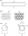
- Fig. 1 is a schematic depiction of a tubular and/or rod-shaped glass article 1.
- the glass article has longest dimension I, likewise depicted in fig. 1 .
- the longest dimension - or simply length I - of the tubular and/or rod-shaped article 1 extends along a first direction of a Cartesian coordinate system, that is, here in this case, from the left to the right of the figure.
- Fig. 2 is a schematic depiction of a close packing of equal circles in the sense of the present disclosure.
- the left close packing may be understood in this case as a cross-sectional view of a bundle of rod-shaped glass articles 11, whereas, in the right of fig. 2 , the right close packing may be understood as a cross-sectional view of a bundle of tubular glass articles 12.
- the arrangement of circles (as in the left of fig. 2 ) or rings (as in the right of fig. 2 ) each consists, in this case, of four different layers of circles or rings, respectively.
- N L the number of layers
- N L the number of layers
- FIG. 3 in the left part is a cross-sectional view of rod-shaped glass article (or glass rod) 11 with outer dimension d o , the latter being equal to the diameter of the cross-section.
- d o outer dimension
- d i inner dimension
- t w 1 ⁇ 2 * d o ⁇ d i .
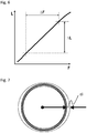
- Fig. 4 depicts in its upper part a) schematically bundle 10, comprising tubular and/or rod-shaped glass articles as well as a thread-like element 2.
- the cross sections of tubular and/or rod-shaped glass articles 1 form a close packing here.
- thread-like element 2 is positioned to the rear of the bundle 10 as well as near the front region. It may be noted that at both position, that is, to the rear and at the front, thread-like element 2 may be the same, that is, just one thread-like element is first wrapped around the glass articles at least partially at the rear side portions and, after that, at the front side portion. However, if may be more suitable to use, at each spacer position, a separate thread-like element 2.
- more than one thread-like element may be present at a single spacer position, for example, an upper thread-like element and a lower thread-like element.
- FIG. 5 a tubular and/or rod-shaped glass article 1 is depicted. It is once again pointed out that these depictions each are merely schematic depictions and not drawn to scale.
- the tubular and/or rod-shaped glass article 1 in each of the four parts a to d of fig. 5 is bent. However, the amount of bending has been exaggerated for illustrational issues.
- Part a) of Fig. 5 shows the case where at least one thread-like element 2 has been positioned at to spacer positions n t along length I of the article 2. These positions may be characterized by distance a, a being a first distance a between the half-length of the tubular and/or rod-shaped articles and at least one first spacer position of at the least one thread-like element.
- these three positions can be characterized by distances a and b, a being a first distance a between the half-length of the tubular and/or rod-shaped articles and at least one first spacer position of at the least one thread-like element and b being a second distance b between the half-length of the tubular and/or rod-shaped articles and at least one second spacer position of the at least one thread-like element; a being smaller than b.
- four spacer positions are distributed along length I. These four position can likewise be characterized by distances a and b, a being a first distance a between the half-length of the tubular and/or rod-shaped articles and at least one first spacer position of at the least one thread-like element and b being a second distance b between the half-length of the tubular and/or rod-shaped articles and at least one second spacer position of the at least one thread-like element; a being smaller than b.
- a, b, and c are characterized by distances a, b, and c, a being a first distance a between the half-length of the tubular and/or rod-shaped articles and at least one first spacer position of at the least one thread-like element, b being a second distance b between the half-length of the tubular and/or rod-shaped articles and at least one second spacer position of the at least one thread-like element, and c a third distance c between the half-length of the tubular and/or rod-shaped articles and at least one third spacer position of at the least one thread-like element, with a being smaller than b and b being smaller than c.
- Distances a, b and c are chosen according to the following table: n t a b c 2 0.25 ⁇ a/L ⁇ 0.29 3 -0.015 ⁇ a/L ⁇ 0.015 0.32 ⁇ b/L ⁇ 0.40 4 0.10 ⁇ a/L ⁇ 0.16 0.36 ⁇ b/L ⁇ 0.43 5 -0.025 ⁇ a/L ⁇ 0.025 0.18 ⁇ b/L ⁇ 0.24 0.38 ⁇ c/L ⁇ 0.44
- the spacer positions are arranged symmetrically, that is, for uneven numbers of spaced positions, when a is 0 or nearly 0.
- d s denotes the maximum distance between spacer positions, that is, the distance between the outermost thread-like elements, and d a , the average distance between adjacent spacer positions.
- a negative a-value means that the a distance deviating from the half length of the glass article to the "left" side (that is, in direction of the "left end") of the glass article as depicted in fig. 5 .
- the average distance d a between adjacent spacers may be about 28.5 cm or else about 33 cm or else about 36 cm or else about 43 cm or else about 48 cm or else about 75 cm or else about 75 cm or else about 87 cm, the average distance may vary depending upon the number of spacers arranged along the length of the glass articles. Further, the average distance will be less for a greater number of spacers.
- the average distance d a between different spacers positions can be determined.
- the actual distance between spacer positions may differ slightly from this average value, especially taking into account the a-value for deviation from a perfect, most preferred symmetrical arrangement of spacer positions, that is, for a value of a ⁇ 0 in cases where there is an uneven number of spacer positions.
- C S L ⁇ ⁇ F ⁇ L , wherein L corresponds to the initial length of the thread-like-element (plotted along the y-axis), ⁇ L is the amount by which the length of the thread-like element changes, and ⁇ F is the change of the tensile force in the thread-like element, as determined in usual load-strain-curves as shown in the schematic diagram of fig. 6 , that is, by the ratio of the strain (or relative elongation of the respective thread-like element ⁇ L/L) and the change of the tensile strength, ⁇ F, in the respective thread-like element.
- Fig. 7 shows schematically the determination of the circularity error, here denoted as ci.
- the circularity error ci in this case, is a measure for the deviation of a given shape from the ideal circular shape, Here, a circumferential line of a cross section has to lie in a plane defined by two concentrical circles (that are depicted in fig. 7 with dotted lines) with a specific, predefined distance from each other.
- the actual value of the circularity error ci is one half of the maximum difference the outer diameters in the respective plane.
- the ovality may be given, the ovality being the difference of the maximum outer cross section and the minimum outer cross section in a direction perpendicular to the length I of a rod-shaped or tubular glass article.
- the ovality is two times the value of the circularity error.
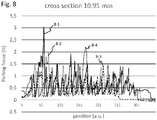
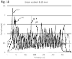
- Figures 8 to 12 show diagrams of pulling forces obtained for thread-like elements 2 in bundles 10 according to embodiments of the present disclosure.
- thread-like elements arranged at a spacer position had been wrapped around the glass articles at least partially in order to space the glass articles apart. Further, the thread-like elements had been wrapped around the glass articles at least partially, forming several knots. These knots were, for each bundle, formed as releasable knots, that is, knots that could easily be untied by pulling one free end of one thread-like element forming the bundle.
- the pulling force (or tension), given in N has been plotted over the position of the puller used for withdrawal of the at least one thread-like element.
- Puller position is given in arbitrary units.
- measurement was conducted for four different layers of glass articles. Furthermore, in all cases, bundles were arranged in a horizontal position.
- the number of knots, in each of the examples used for measurement corresponded to the number of glass articles in a layer. Maximum values correspond to untying of the knot and, thus, to the maximum adhesive force of the knot. Therefore, the maximum measured value corresponds to the minimum value of tension needed for untying of a knot.
- measured tension values correspond to those stages of unpacking wherein simple withdrawal of the thread-like element takes place. In consequence, as no adhesive force of a knot needs to be overcome, much less tension is needed in these stages.
- Fig. 8 is a diagram depicting pulling forces measured in bundles of tubular and/or rod shaped glass articles with cross sections of 10.95 mm, indicated as data sets 8-1, 8-2, 8-3 and 8-4.
- the statistical nature of minimum pulling force or maximum adhesive force of a knot can clearly be seen, as peak values obtained during measurement may range from a value of slightly more than 3 N (data set 8-1, first peak value) to less than 1.5 N or even less (data set 8-3), with an average value of about 2.2 N.
- Fig. 9 depicts pulling force over puller position for bundles of tubular and/or rod-shaped glass articles with a cross section of about 16 mm, indicated as data sets 9-1, 9-2, 9-3 and 9-4.
- Minimum pulling forces ranged from 1.1 N or even less (data set 9-3) to a value of 2.13 N (data set 9.1), with an average of about 1.6 N.
- Fig. 11 depicting data sets 11-1, 11-2, 11-3 and 11-4, for cross sections of glass articles of about 8.65 mm, shows a peak value of the pulling force of about 2.4 N (data set 11-2), whereas for some knots, a pulling force as low as 1.4 N (11-3) or even less proved sufficient for releasing tied knots. Average "minimum pulling force" amounted to about 2 N.
- fig. 12 depicts data sets 12-1, 12-2, 12-3 and 12-4, for cross sections of bundled glass articles of about 42 mm.
- a peak value of 1.3 N was obtained for set 12-2, whereas pulling forces for releasing knots could also be as low as 0.7 N (set 12-1) or lesser still, for example 0.4 N (set 12-2).
- Average was about 0.9 N.
Landscapes
- Engineering & Computer Science (AREA)
- Mechanical Engineering (AREA)
- Packaging Of Annular Or Rod-Shaped Articles, Wearing Apparel, Cassettes, Or The Like (AREA)
- Packages (AREA)
- Packaging Frangible Articles (AREA)
Applications Claiming Priority (1)
| Application Number | Priority Date | Filing Date | Title |
|---|---|---|---|
| EP20160479 | 2020-03-02 |
Publications (1)
| Publication Number | Publication Date |
|---|---|
| EP3875396A1 true EP3875396A1 (fr) | 2021-09-08 |
Family
ID=69743180
Family Applications (1)
| Application Number | Title | Priority Date | Filing Date |
|---|---|---|---|
| EP21160015.0A Withdrawn EP3875396A1 (fr) | 2020-03-02 | 2021-03-01 | Faisceau d'articles en verre tubulaire et/ou en forme de tige, son procédé de fabrication ainsi que pour le déballage dudit faisceau |
Country Status (4)
| Country | Link |
|---|---|
| US (2) | US11708201B2 (fr) |
| EP (1) | EP3875396A1 (fr) |
| JP (1) | JP2021138454A (fr) |
| CN (1) | CN113335762A (fr) |
Families Citing this family (3)
| Publication number | Priority date | Publication date | Assignee | Title |
|---|---|---|---|---|
| EP3875395A1 (fr) * | 2020-03-02 | 2021-09-08 | Schott Ag | Faisceau d'articles en verre en forme tubulaire et/ou de tige, son procédé de fabrication, ainsi que de déballage dudit faisceau |
| CN116395272A (zh) * | 2023-02-04 | 2023-07-07 | 航珍航空技术(上海)有限公司 | 导管存储仓 |
| US12312109B2 (en) * | 2023-06-02 | 2025-05-27 | Slab Innovation Inc. | Adaptable spacer roping installation system for casted concrete products or the likes and palletizing system therewith |
Citations (12)
| Publication number | Priority date | Publication date | Assignee | Title |
|---|---|---|---|---|
| DD82301A (fr) | ||||
| US3294225A (en) | 1965-04-26 | 1966-12-27 | Corning Glass Works | Combined shipping package and protective armor for glass pipe |
| US3373540A (en) | 1965-07-13 | 1968-03-19 | Corning Glass Works | Method of bundling |
| DE2729966A1 (de) | 1977-07-02 | 1979-01-18 | Schott Ruhrglas | Verfahren zum verpacken von roehren oder staeben |
| US4385696A (en) | 1981-08-21 | 1983-05-31 | Wayne H. Coloney Company, Inc. | Linked container article carrier |
| EP0132587A1 (fr) | 1983-06-20 | 1985-02-13 | IBS Technik AG Engineering und Maschinenbau | Faisceau de tubes |
| DD224555A1 (de) | 1984-03-29 | 1985-07-10 | Jenaer Glaswerk Veb | Verfahren zum schrumpffolienverpacken von glasrohren oder glasstaeben |
| JPH09295686A (ja) | 1996-04-26 | 1997-11-18 | Nippon Electric Glass Co Ltd | ガラス管包装体 |
| DE4225876C2 (de) | 1992-08-05 | 2001-10-11 | Schott Rohrglas Gmbh | Packaufnahme und Verfahren sowie Vorrichtung zur Herstellung mindestens einer Packaufnahme für stabförmige Gegenstände |
| DE20121582U1 (de) | 2001-08-24 | 2003-02-27 | Schott Glas, 55122 Mainz | Verpackung für Glasrohre |
| US20120326442A1 (en) * | 2010-10-05 | 2012-12-27 | Ideal Industries, Inc. | Knot tying device and cartridge system for providing tying filament thereto |
| WO2015037361A1 (fr) | 2013-09-13 | 2015-03-19 | 日本電気硝子株式会社 | Emballage de tubes de verre |
Family Cites Families (35)
| Publication number | Priority date | Publication date | Assignee | Title |
|---|---|---|---|---|
| DE82301C (fr) | ||||
| DE224556C (fr) | ||||
| US2059390A (en) * | 1932-11-14 | 1936-11-03 | Signode Steel Strapping Co | Transportation of pipe |
| US2300059A (en) * | 1940-12-28 | 1942-10-27 | Signode Steel Strapping Co | Transportation of cylindrical objects |
| US2284616A (en) * | 1941-05-13 | 1942-05-26 | Don F Hedges | Means for and method of assembling metallic articles and the like for shipment |
| US2350752A (en) | 1941-12-01 | 1944-06-06 | Electric Storage Battery Co | Plate for secondary or storage batteries |
| US2662649A (en) * | 1951-07-27 | 1953-12-15 | American Can Co | Shipping package |
| US2991089A (en) * | 1956-06-18 | 1961-07-04 | Stuart Robert | Shipping package |
| US3143266A (en) | 1961-10-04 | 1964-08-04 | Imatake Midorl | Self-tightening article carrier |
| US3263830A (en) * | 1964-02-05 | 1966-08-02 | Union Metal Mfg Co | Package loading of poles |
| US3611656A (en) | 1970-04-24 | 1971-10-12 | Container Corp | Method and apparatus for forming carriers for container groups |
| US3802987A (en) * | 1972-03-23 | 1974-04-09 | Corning Glass Works | Method of joining |
| GB1462626A (en) * | 1973-07-21 | 1977-01-26 | Paton Co Ltd Calvert | Packaged tubes |
| US4137821A (en) | 1977-05-27 | 1979-02-06 | Tesseract Corporation | Article handling belt |
| US4693167A (en) * | 1985-03-25 | 1987-09-15 | Howden Coloney, Inc. | Strap for linked container article carrier |
| DE3701556C1 (de) | 1987-01-21 | 1988-06-01 | Mannesmann Ag | Verfahren und Einrichtung zum Manipulieren von kleinkalibrigen Rohren sowie Fertigungseinrichtungen und eine Behandlungseinrichtung,insbesondere fuer Brems-,Kraftstoff- oder Hydraulikleitungen |
| JPH0431230A (ja) * | 1990-05-14 | 1992-02-03 | Hokkai Can Co Ltd | 梱包体の結束紐除去方法及びその装置 |
| FR2675776B1 (fr) * | 1991-04-26 | 1993-07-16 | Rivory Joanny Ind | Dispositif de verrouillage pour sangles de paquetage et de levage. |
| US5294222A (en) * | 1992-03-10 | 1994-03-15 | Mobil Oil Corporation | Method of preventing damage to pipe joints during shipment |
| DE4410854B4 (de) | 1994-03-29 | 2006-08-24 | Norbert Fleuren | Transportkarton zum Transport rohrförmiger Leuchtstofflampen |
| US7192069B1 (en) * | 1996-06-27 | 2007-03-20 | Handle It Llc | Wrap for bundling objects |
| US6915619B2 (en) | 2001-08-10 | 2005-07-12 | Baxa Corporation | Method for handling syringe bodies |
| US6638133B1 (en) * | 2002-04-11 | 2003-10-28 | Ronnie Lynn Brancolino | Lady's hair accessory doll |
| FR2843366B1 (fr) * | 2002-08-06 | 2005-03-11 | Pack Ind Sa | Dispositif d'entrelacage pour machine de palettisation et machine de palettisation equipee d'un tel dispositif |
| FR2874596A1 (fr) * | 2004-08-27 | 2006-03-03 | Lignum Consultant Sarl | Dispositif pour maintenir en faisceau des objets longs |
| US7186066B2 (en) * | 2005-05-04 | 2007-03-06 | Gse Lining Technology | Method of loading and unloading transported compressible rolls |
| DE102005020892A1 (de) | 2005-05-04 | 2006-11-09 | Saint-Gobain Isover G+H Ag | Verpackungseinheit für Rohrschalen |
| CN101905785A (zh) | 2010-07-28 | 2010-12-08 | 中国人民解放军后勤工程学院 | 一种管子集束装置 |
| WO2012075089A1 (fr) | 2010-11-30 | 2012-06-07 | Corning Incorporated | Emballages et procédés d'emballage de feuilles de verre |
| AT12992U1 (de) | 2011-09-22 | 2013-03-15 | Inova Lisec Technologiezentrum | Vorrichtung zum Einlegen von Distanzschnüren |
| US20150267844A1 (en) * | 2014-03-24 | 2015-09-24 | Ideal Industries, Inc. | Cable lacing tie devices and methods of using the same |
| US9981791B2 (en) * | 2015-12-22 | 2018-05-29 | Thomas & Betts International Llc | Modular packaging and shipping assembly |
| CN105501705B (zh) | 2015-12-26 | 2018-01-26 | 宁波远志立方能源科技有限公司 | 一种用于玻璃运输的包装材料 |
| NL1042016B1 (nl) * | 2016-08-22 | 2018-03-01 | Alcomij Beheer B V | Wijze van verpakken in een bundel |
| DE102018221782A1 (de) * | 2018-12-14 | 2020-06-18 | Schott Ag | Glaskörperlage, Glaskörperbündel sowie Packverfahren |
-
2021
- 2021-03-01 JP JP2021031393A patent/JP2021138454A/ja active Pending
- 2021-03-01 EP EP21160015.0A patent/EP3875396A1/fr not_active Withdrawn
- 2021-03-02 US US17/190,311 patent/US11708201B2/en active Active
- 2021-03-02 CN CN202110231095.8A patent/CN113335762A/zh active Pending
-
2023
- 2023-06-05 US US18/329,236 patent/US20230312199A1/en not_active Abandoned
Patent Citations (12)
| Publication number | Priority date | Publication date | Assignee | Title |
|---|---|---|---|---|
| DD82301A (fr) | ||||
| US3294225A (en) | 1965-04-26 | 1966-12-27 | Corning Glass Works | Combined shipping package and protective armor for glass pipe |
| US3373540A (en) | 1965-07-13 | 1968-03-19 | Corning Glass Works | Method of bundling |
| DE2729966A1 (de) | 1977-07-02 | 1979-01-18 | Schott Ruhrglas | Verfahren zum verpacken von roehren oder staeben |
| US4385696A (en) | 1981-08-21 | 1983-05-31 | Wayne H. Coloney Company, Inc. | Linked container article carrier |
| EP0132587A1 (fr) | 1983-06-20 | 1985-02-13 | IBS Technik AG Engineering und Maschinenbau | Faisceau de tubes |
| DD224555A1 (de) | 1984-03-29 | 1985-07-10 | Jenaer Glaswerk Veb | Verfahren zum schrumpffolienverpacken von glasrohren oder glasstaeben |
| DE4225876C2 (de) | 1992-08-05 | 2001-10-11 | Schott Rohrglas Gmbh | Packaufnahme und Verfahren sowie Vorrichtung zur Herstellung mindestens einer Packaufnahme für stabförmige Gegenstände |
| JPH09295686A (ja) | 1996-04-26 | 1997-11-18 | Nippon Electric Glass Co Ltd | ガラス管包装体 |
| DE20121582U1 (de) | 2001-08-24 | 2003-02-27 | Schott Glas, 55122 Mainz | Verpackung für Glasrohre |
| US20120326442A1 (en) * | 2010-10-05 | 2012-12-27 | Ideal Industries, Inc. | Knot tying device and cartridge system for providing tying filament thereto |
| WO2015037361A1 (fr) | 2013-09-13 | 2015-03-19 | 日本電気硝子株式会社 | Emballage de tubes de verre |
Also Published As
| Publication number | Publication date |
|---|---|
| US20230312199A1 (en) | 2023-10-05 |
| JP2021138454A (ja) | 2021-09-16 |
| US11708201B2 (en) | 2023-07-25 |
| CN113335762A (zh) | 2021-09-03 |
| US20210269207A1 (en) | 2021-09-02 |
Similar Documents
| Publication | Publication Date | Title |
|---|---|---|
| US12246908B2 (en) | Bundle of tubular and/or rod-shaped glass articles, method for its fabrication as well as for unpacking said bundle | |
| US20230312199A1 (en) | Bundle of tubular and/or rod-shaped glass articles, method for its fabrication as well as for unpacking said bundle | |
| US11352197B2 (en) | Glass article layer, glass article bundle, and packing method | |
| US3983997A (en) | Yarn package and method for mixing and dispensing | |
| GB2065733A (en) | Plastic netting for pallet load wrapping | |
| US11873158B2 (en) | Glass article layer, glass article bundle, and method for producing a glass article layer | |
| US3373540A (en) | Method of bundling | |
| KR101520361B1 (ko) | 롤 스톡용 보빈 | |
| WO2022076396A1 (fr) | Distributeur pour bande continue d'un substrat supportant des articles sensibles à la flexion | |
| US20130214077A1 (en) | Method of Packaging a Continuous Length of Product on a Spool using Indexed Layers | |
| JP3131636U (ja) | 糸条巻取体の積層梱包体 | |
| EP2695826A1 (fr) | Ensemble pour le transport de bobines de feuilles enroulées et procédé de disposition d'une étiquette sur un récipient | |
| CN101277878B (zh) | 玻璃长纤维丝饼的放置·搬运方法以及包装体 | |
| JP4587116B2 (ja) | ガラスロービング梱包体及びガラスロービングの梱包方法 | |
| WO2016061515A1 (fr) | Articles de lien de bavette perforés et leurs procédés de fabrication et d'utilisation | |
| KR20140002395U (ko) | 양파 운반용 대형 망사자루 | |
| CN208603012U (zh) | 一种玻纤短切原丝毡产品的包装结构 | |
| US8732912B2 (en) | Strap with improved column stiffness | |
| JP2007069985A (ja) | ガラスロービング包装体、ガラスロービング梱包体及びその梱包方法 | |
| JP5381835B2 (ja) | ガラス繊維束包装体及びガラス繊維束包装体の製造方法 | |
| JPS6246427B2 (fr) | ||
| US20200024017A1 (en) | Insulation packaging system | |
| US20180057231A1 (en) | Insulation packaging system | |
| ITBS970081A1 (it) | Supporto accatastabile per materiali in bobina o rotoli |
Legal Events
| Date | Code | Title | Description |
|---|---|---|---|
| PUAI | Public reference made under article 153(3) epc to a published international application that has entered the european phase |
Free format text: ORIGINAL CODE: 0009012 |
|
| STAA | Information on the status of an ep patent application or granted ep patent |
Free format text: STATUS: THE APPLICATION HAS BEEN PUBLISHED |
|
| AK | Designated contracting states |
Kind code of ref document: A1 Designated state(s): AL AT BE BG CH CY CZ DE DK EE ES FI FR GB GR HR HU IE IS IT LI LT LU LV MC MK MT NL NO PL PT RO RS SE SI SK SM TR |
|
| STAA | Information on the status of an ep patent application or granted ep patent |
Free format text: STATUS: REQUEST FOR EXAMINATION WAS MADE |
|
| 17P | Request for examination filed |
Effective date: 20220217 |
|
| RBV | Designated contracting states (corrected) |
Designated state(s): AL AT BE BG CH CY CZ DE DK EE ES FI FR GB GR HR HU IE IS IT LI LT LU LV MC MK MT NL NO PL PT RO RS SE SI SK SM TR |
|
| P01 | Opt-out of the competence of the unified patent court (upc) registered |
Effective date: 20230516 |
|
| STAA | Information on the status of an ep patent application or granted ep patent |
Free format text: STATUS: EXAMINATION IS IN PROGRESS |
|
| 17Q | First examination report despatched |
Effective date: 20230821 |
|
| STAA | Information on the status of an ep patent application or granted ep patent |
Free format text: STATUS: THE APPLICATION IS DEEMED TO BE WITHDRAWN |
|
| 18D | Application deemed to be withdrawn |
Effective date: 20251001 |