EP3876053A1 - Procédé de détection d'erreurs d'adressage et appareil de terrain - Google Patents
Procédé de détection d'erreurs d'adressage et appareil de terrain Download PDFInfo
- Publication number
- EP3876053A1 EP3876053A1 EP20160979.9A EP20160979A EP3876053A1 EP 3876053 A1 EP3876053 A1 EP 3876053A1 EP 20160979 A EP20160979 A EP 20160979A EP 3876053 A1 EP3876053 A1 EP 3876053A1
- Authority
- EP
- European Patent Office
- Prior art keywords
- fcs
- block check
- bid
- bid1
- value
- Prior art date
- Legal status (The legal status is an assumption and is not a legal conclusion. Google has not performed a legal analysis and makes no representation as to the accuracy of the status listed.)
- Withdrawn
Links
Images



Classifications
-
- G—PHYSICS
- G05—CONTROLLING; REGULATING
- G05B—CONTROL OR REGULATING SYSTEMS IN GENERAL; FUNCTIONAL ELEMENTS OF SUCH SYSTEMS; MONITORING OR TESTING ARRANGEMENTS FOR SUCH SYSTEMS OR ELEMENTS
- G05B19/00—Program-control systems
- G05B19/02—Program-control systems electric
- G05B19/418—Total factory control, i.e. centrally controlling a plurality of machines, e.g. direct or distributed numerical control [DNC], flexible manufacturing systems [FMS], integrated manufacturing systems [IMS] or computer integrated manufacturing [CIM]
- G05B19/4185—Total factory control, i.e. centrally controlling a plurality of machines, e.g. direct or distributed numerical control [DNC], flexible manufacturing systems [FMS], integrated manufacturing systems [IMS] or computer integrated manufacturing [CIM] characterised by the network communication
- G05B19/4186—Total factory control, i.e. centrally controlling a plurality of machines, e.g. direct or distributed numerical control [DNC], flexible manufacturing systems [FMS], integrated manufacturing systems [IMS] or computer integrated manufacturing [CIM] characterised by the network communication by protocol, e.g. MAP, TOP
-
- H—ELECTRICITY
- H03—ELECTRONIC CIRCUITRY
- H03M—CODING; DECODING; CODE CONVERSION IN GENERAL
- H03M13/00—Coding, decoding or code conversion, for error detection or error correction; Coding theory basic assumptions; Coding bounds; Error probability evaluation methods; Channel models; Simulation or testing of codes
- H03M13/03—Error detection or forward error correction by redundancy in data representation, i.e. code words containing more digits than the source words
- H03M13/05—Error detection or forward error correction by redundancy in data representation, i.e. code words containing more digits than the source words using block codes, i.e. a predetermined number of check bits joined to a predetermined number of information bits
- H03M13/09—Error detection only, e.g. using cyclic redundancy check [CRC] codes or single parity bit
-
- H—ELECTRICITY
- H04—ELECTRIC COMMUNICATION TECHNIQUE
- H04L—TRANSMISSION OF DIGITAL INFORMATION, e.g. TELEGRAPHIC COMMUNICATION
- H04L1/00—Arrangements for detecting or preventing errors in the information received
- H04L1/004—Arrangements for detecting or preventing errors in the information received by using forward error control
- H04L1/0041—Arrangements at the transmitter end
-
- H—ELECTRICITY
- H04—ELECTRIC COMMUNICATION TECHNIQUE
- H04L—TRANSMISSION OF DIGITAL INFORMATION, e.g. TELEGRAPHIC COMMUNICATION
- H04L1/00—Arrangements for detecting or preventing errors in the information received
- H04L1/004—Arrangements for detecting or preventing errors in the information received by using forward error control
- H04L1/0045—Arrangements at the receiver end
-
- H—ELECTRICITY
- H04—ELECTRIC COMMUNICATION TECHNIQUE
- H04L—TRANSMISSION OF DIGITAL INFORMATION, e.g. TELEGRAPHIC COMMUNICATION
- H04L1/00—Arrangements for detecting or preventing errors in the information received
- H04L1/004—Arrangements for detecting or preventing errors in the information received by using forward error control
- H04L1/0056—Systems characterized by the type of code used
- H04L1/0061—Error detection codes
-
- G—PHYSICS
- G05—CONTROLLING; REGULATING
- G05B—CONTROL OR REGULATING SYSTEMS IN GENERAL; FUNCTIONAL ELEMENTS OF SUCH SYSTEMS; MONITORING OR TESTING ARRANGEMENTS FOR SUCH SYSTEMS OR ELEMENTS
- G05B2219/00—Program-control systems
- G05B2219/20—Pc systems
- G05B2219/25—Pc structure of the system
- G05B2219/25157—Checksum CRC
-
- Y—GENERAL TAGGING OF NEW TECHNOLOGICAL DEVELOPMENTS; GENERAL TAGGING OF CROSS-SECTIONAL TECHNOLOGIES SPANNING OVER SEVERAL SECTIONS OF THE IPC; TECHNICAL SUBJECTS COVERED BY FORMER USPC CROSS-REFERENCE ART COLLECTIONS [XRACs] AND DIGESTS
- Y02—TECHNOLOGIES OR APPLICATIONS FOR MITIGATION OR ADAPTATION AGAINST CLIMATE CHANGE
- Y02P—CLIMATE CHANGE MITIGATION TECHNOLOGIES IN THE PRODUCTION OR PROCESSING OF GOODS
- Y02P90/00—Enabling technologies with a potential contribution to greenhouse gas [GHG] emissions mitigation
- Y02P90/02—Total factory control, e.g. smart factories, flexible manufacturing systems [FMS] or integrated manufacturing systems [IMS]
Definitions
- the invention relates to a method for uncovering addressing errors in a fail-safe communication connection between an automation device and a field device, an F-address being used for the fail-safe communication connection, which includes a code name and a base identifier, for sending a message from the automation device to the field device with the help of a checksum calculation from data to be sent and from a status byte under the influence of the code name assigned for the respective connection, a block check string is formed.
- the invention also relates to a field device designed to reveal addressing errors in a fail-safe communication connection with an automation device, an F-address comprising a code name and a base identifier being used for the fail-safe communication connection.
- fail-safe communication connection is understood to mean the definition of functional safety during communication in automation systems from the IEC 61508 standard.
- PROFIsafe system description, technology and application describes the implementation of a safety-related communication and in particular a safe connection identification with Profibus and Profinet protocols.
- an address relationship including a target and a source address, for example for Profinet participants, must be unique across the network.
- the PROFIsafe safety protocol is an example of a safety-related communication protocol.
- PROFIsafe a 32-bit code name, which corresponds to an address relationship, is used for unique connection identification.
- the disadvantage of this is that the code names cannot be assigned uniquely anywhere in the world.
- An F address is a unique address relationship between two communication participants. In a communication designed for functional safety, the F address is used to uniquely identify a source and a target. Each F-I / O therefore has two address parts: F-source address, F-destination address. One or both parts of the address can be used for protection.
- PROFIsafe connections for example, a unique code name (32-bit) is assigned to detect address errors. In This must not occur more than once in an industrial plant, which must be ensured by organizational measures (e.g. list or database).
- the code name and the BID can then be taken into account in a CRC calculation (sender) and CRC check (receiver).
- CRC calculation sends a frame Check Sequence (FCS) in a telegram depends on the code name and the BID.
- FCS Frame Check Sequence
- either the code name or the BID in the recipient would not match the respective expected value.
- a CRC check would therefore have a high probability of failing.
- a method is therefore proposed to solve the problem, which can be implemented, for example, in safety-related devices such as I / O module drives etc. without having to make changes to safety-related software layers.
- the object is then achieved in that, starting from a first automation device with a first basic identifier as the sender of the message for a first field device as the recipient of the message, a new block check sequence is generated from the block check sequence that has already been calculated Arithmetic rule with at least one value, which was derived from the first base identifier, on the block check character sequence results in the new block check character sequence, and the new block check character sequence calculated in this way is sent in the message Block check string with the aid of the calculation rule with which at least one value the block check string is calculated back and with the help of a checksum check from the data to be received and from the status byte under the influence of the first code name assigned for this connection, an expected block check string is calculated, the expected block check string being calculated with the back calculated The block check string is compared and an error message is generated if they are not equal.
- FCS frame check sequence
- the step in which the block check character sequence is calculated back from the new block check character sequence with the aid of the arithmetic rule with the at least one value and, based on a layer structure in the field device, is carried out in a non-security layer and the remaining steps are carried out in a Security layer of the field device executed.
- the address component of the automation device namely the basic identifier (BID)
- BID basic identifier
- a further improvement of the method is obtained if a first value and a second value are derived from the basic identifier and the first value corresponds to a first ranking of bits and the second value to a second ranking of bits of the basic identifier.
- a further optimization of the method or an increase in the probability of an error being discovered is achieved by using a toggle bit from the status byte to generate the new block check string in order to use the first value or the second value alternately.
- the aim of the invention is finally to use the aforementioned method in field devices which are already designed as safety-related devices for process automation, the method being able to be carried out without having to make changes to safety-related software layers of the device.
- a field device which is designed to reveal addressing errors in a fail-safe communication connection with an automation device, an F-address being used for the fail-safe communication connection, which comprises a code name and a base identifier, whereby for sending a message from the automation device to the field device with the aid of a checksum calculation from data to be sent and from a status byte under the influence of the code name assigned for the respective connection, a block check character sequence is formed, and a new block check character sequence resulting from the application of a calculation rule with at least one value derived from the respective base identifier to the block check character sequence, and the new block check character sequence calculated in this way is in the message and is thus received by the field device, further configured with a division into a secure layer in which security-related software components are stored executable and in a non-secure layer in which applications not designed for security run independently of the security-related tasks, with the non-secure layer, an additional means for receiving a basic identifier extension is
- a first series machine S1 is connected via a first network N1 with a switch SW to a second series machine S2, which is connected to the switch SW via a network N2.
- the first series machine S1 has a first automation device PLC1, to which a first field device D1, a second field device D2 and a third field device D3 are connected via the first network N1.
- a fail-safe communication connection is established between the first automation device PLC 1 and the field devices D1, D2, D3.
- F-addresses are part of the configuration of the first automation device PLC1 and the field devices D1, D2, D3.
- a connection from the first automation device PLC1 to the first field device D1 is shown as an example, with F-ADR CN1, BID1 being entered for the F-address.
- Corresponding code names for the connections are accordingly stored in the first automation device PLC1 for the connection to be established to the field devices D1, D2, D3.
- a first code name CN1 stands for a connection to the first field device D1
- a second code name CN2 stands for a connection to the second field device D2
- a third code name CN3 stands for a connection to the third Field device D3.
- the address relationship of the F-address is therefore stored in the first automation device PLC1 as a pair from CN1, BID1; CN2, BID1; CN3, BID1.
- the pair of the address relationship is also stored in the respective field device D1, D2, D3, the first field device D1 having the code name CN1, the second field device D2 having the code name CN2 and the third field device D3 having the code name CN3.
- the field devices D1, D2, D3 all have the same basic identifier, namely the first basic identifier BID1.
- a second base identifier BID2 is assigned to the second automation device PLC2 for address uniqueness.
- the field devices D1, D2, D3 associated with the second automation device PLC2 also have the second basic identifier BID2.
- FIG 1 a globally unique addressing can now also be guaranteed across network boundaries.
- the main disadvantage in solving it FIG 1 is that in the field devices D1, D2, D3 a change must be made to a safety-related layer, eg PROFIsafe layer, in order to insert the first basic identifier BID1 or the second basic identifier BID2.
- a safety-related layer eg PROFIsafe layer
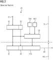
- FIG 2 shows a sequence in a transmitter, namely the first automation device PLC1, as shown in FIG FIG 1 is shown.
- security-relevant operations are carried out in a security layer SL and non-security-relevant operations, such as the sending of the telegram in a non-security layer NSL.
- a telegram is sent in a so-called black channel.
- FIG 2 are in the security flyer SL from data to be sent 21 in a packet of user data 22 combined with a status byte SC.
- These two data are calculated by means of a checksum calculation 23 with the aid of a CRC calculation, the code name CN1 and the first basic identifier BID1 also being included in the checksum calculation.
- This calculation results in a block check string FCS which is sent with the user data 22 and the status byte SC as a message Ml to be sent.
- FIG 3 is the counterpart to the in FIG 2 described transmission process of the message Ml now a receiving process 30 is shown.
- the message Ml now received is divided into user data 22, the status byte SC and the block check string FCS.
- the aforementioned data is still in the non-security layer NSL.
- the data is now sent to the security layer SL for evaluation.
- a block check character sequence FCS e is recalculated as an expected calculated value within the security layer SL by means of a checksum check.
- This expected back- calculated block check string value FCS e is compared with the block check string FCS contained in the message Ml via a comparison means 32; if they are not equal, an error is signaled and that means there was an addressing error.
- FIG 4 an overview 40 of the inventive expansion of a test for a basic identifier is shown. Also in the FIG 4 a differentiation between security layer SL and non-security layer NSL has been introduced again by means of a dash-dot line.
- a sender side is shown as an example, which in the example relates to FIG 1 , corresponds to the first automation device PLC1.
- a transmitter application 43 is connected to a PROFIsafe driver transmitter (host) 45.
- a basic identifier extension (on the transmitter side) 47 is arranged between a black channel BC and the PROFIsafe driver 45.
- a new block check string FCS ' is generated in which parts of the first basic identifier BID are received in order to later add the basic identifier BID for extended addressing error detection.
- the extended telegram or the telegram which is enriched with a modified block check character sequence FCS ', is now sent via a transmission path Ü.
- the telegram or the message Ml contains user data 22, a status byte SC and the changed, new block check string FCS '.
- the receiver corresponds to the first field device D1, for example FIG 1 , right side of the block diagram.
- the dash-dotted line which distinguishes between the security layer SL and the non-security layer NSL, has shifted slightly on the receiver side, which also shows the decisive advantage of the invention.
- a basic identifier extension (on the receiver side) 48 no longer has to be used, as was previously the case in FIG 1 described, can be implemented in a advocateslyer SL, but can be implemented or accommodated in a non-security layer NSL, this offers the decisive advantage that with existing field devices a PROFIsafe driver (device) 46 is no longer technically improved or changed and re-tested must become.
- a receiver application 44 is also located in the receiver above the PROFIsafe driver 46.
- a first code name CN1 and a first base identifier BID1 are entered in the message M1 or in the as follows telegram to be sent incorporated.
- the code name for the connection to the first field device is D1 known, namely the first code name CN1.
- the first basic identifier BID1 of the automation device PLC1 is also known.
- an F-address F-Adr is therefore used, which on the one hand includes the first code name CN1 and on the other hand the first basic identifier BID1, for sending the message M1 from the first automation device PLC1 to the first field device D1 with the aid of a checksum calculation 33, CRC from data 21 to be sent and from a status byte SC under the influence of the first code name CN1 assigned for the respective connection, a block check string FCS is formed.
- a new block check sequence FCS ' is now generated from the block check character sequence FCS that has already been calculated.
- This generation takes place as follows: Using a calculation rule F with at least one value BID1_L, BID1_H, which was derived from the first base identifier BID1, the block check character sequence FCS with the calculation rule and the value is changed to a newly calculated block check character sequence FCS '.
- This newly generated block check string FCS ' is sent in the message M1.
- An alternative option for using a value derived from the basic identifier BID1 is that a toggle bit T from the status byte SC is used to generate the new block check string FCS 'in order to use either the first value BID1_L or the second value BID1_H alternately .
- the message M1 'received now has the user data 22, the status byte SC and the new block check string FCS' in its telegram.
- FIG 7 is again divided into a security layer SL and a non-security layer NSL by a dash-dotted line. What is special here is that the back calculation from the new block check character sequence FCS 'into the conventional block check character sequence FCS is now carried out in the non-security layer NSL.
- the first basic identifier BID1 is known, which is why a first value or a second value BID1_L, BID1_H can be generated again from the first basic identifier in the non-security layer NSL, which can be generated with the aid of the calculation rule with the received new block check character sequence FCS ' is linked and thereby the original block check string FCS is obtained, which has accordingly been recalculated from the new, changed block check string FCS '.
- the result of the recalculated block check character sequence FCS can now be brought from the non-security layer NSL into the security layer SL via an interface 84.
- the further operations for the detection of addressing errors can now be carried out in a safety-oriented manner.
- an expected check character sequence FCS e is calculated from the data 22 to be received and the status byte under the influence of the first code name CN1 assigned for this connection.
- the expected block check string FCS e is compared with the recalculated block check string FCS, and if they are not equal, an error message is generated via the comparison means 32.
- FIG 8 shows a field device D1, which is divided into a secure layer 80 and a non-secure layer 81.
- secure layer 80 security-related software components 82 and the first code name CN1 are stored. This is also common practice with previously operated PROFIsafe field devices.
- a memory area SB is now provided in the non-secure layer 81, in which the respective basic identifier BID, in this case the first basic identifier BID1, is stored.
- the respective basic identifier BID in this case the first basic identifier BID1
- the basic identifier extension 48 is designed to reveal an addressing error the calculation rule F with the value BID_L, BID_H, which is now derived from the stored first base identifier BID1, to calculate back the block check character sequence FCS.
- the recalculated block check character sequence FCS can be transmitted to the secure layer 80 via an interface 84 and, as previously known, or also with the security-related software components 82 FIG 3 respectively.
- FIG 7 explained, a possible addressing error can now be uncovered via the CRC check and the later comparison of the two block check character strings.
Landscapes
- Engineering & Computer Science (AREA)
- Computer Networks & Wireless Communication (AREA)
- Signal Processing (AREA)
- Physics & Mathematics (AREA)
- General Engineering & Computer Science (AREA)
- Manufacturing & Machinery (AREA)
- Quality & Reliability (AREA)
- General Physics & Mathematics (AREA)
- Automation & Control Theory (AREA)
- Probability & Statistics with Applications (AREA)
- Theoretical Computer Science (AREA)
- Detection And Prevention Of Errors In Transmission (AREA)
Priority Applications (1)
| Application Number | Priority Date | Filing Date | Title |
|---|---|---|---|
| EP20160979.9A EP3876053A1 (fr) | 2020-03-04 | 2020-03-04 | Procédé de détection d'erreurs d'adressage et appareil de terrain |
Applications Claiming Priority (1)
| Application Number | Priority Date | Filing Date | Title |
|---|---|---|---|
| EP20160979.9A EP3876053A1 (fr) | 2020-03-04 | 2020-03-04 | Procédé de détection d'erreurs d'adressage et appareil de terrain |
Publications (1)
| Publication Number | Publication Date |
|---|---|
| EP3876053A1 true EP3876053A1 (fr) | 2021-09-08 |
Family
ID=69770659
Family Applications (1)
| Application Number | Title | Priority Date | Filing Date |
|---|---|---|---|
| EP20160979.9A Withdrawn EP3876053A1 (fr) | 2020-03-04 | 2020-03-04 | Procédé de détection d'erreurs d'adressage et appareil de terrain |
Country Status (1)
| Country | Link |
|---|---|
| EP (1) | EP3876053A1 (fr) |
Citations (2)
| Publication number | Priority date | Publication date | Assignee | Title |
|---|---|---|---|---|
| DE102013204371A1 (de) * | 2013-03-13 | 2014-09-18 | Beckhoff Automation Gmbh | Verfahren und Bussystem zum protokollunabhängigen Übertragen von Standarddatenpaketen mit Sicherheitsdaten |
| EP2814193A1 (fr) * | 2013-06-14 | 2014-12-17 | Siemens Aktiengesellschaft | Procédé et système de détection d'erreurs lors de la transmission de données d'un émetteur à au moins un récepteur |
-
2020
- 2020-03-04 EP EP20160979.9A patent/EP3876053A1/fr not_active Withdrawn
Patent Citations (2)
| Publication number | Priority date | Publication date | Assignee | Title |
|---|---|---|---|---|
| DE102013204371A1 (de) * | 2013-03-13 | 2014-09-18 | Beckhoff Automation Gmbh | Verfahren und Bussystem zum protokollunabhängigen Übertragen von Standarddatenpaketen mit Sicherheitsdaten |
| EP2814193A1 (fr) * | 2013-06-14 | 2014-12-17 | Siemens Aktiengesellschaft | Procédé et système de détection d'erreurs lors de la transmission de données d'un émetteur à au moins un récepteur |
Non-Patent Citations (2)
| Title |
|---|
| "PROFIsafe Systembeschreibung, Technologie und Anwendung", November 2010 |
| TINA MATTES ET AL: "Analysis of Nested CRC with Additional Net Data in Communication", 22 September 2008, COMPUTER SAFETY, RELIABILITY, AND SECURITY; [LECTURE NOTES IN COMPUTER SCIENCE], SPRINGER BERLIN HEIDELBERG, BERLIN, HEIDELBERG, PAGE(S) 126 - 138, ISBN: 978-3-540-87697-7, XP019106600 * |
Similar Documents
| Publication | Publication Date | Title |
|---|---|---|
| DE102009042354C5 (de) | Verfahren und Vorrichtung zur sicherheitsgerichteten Kommunikation im Kommunikations-Netzwerk einer Automatisierungs-Anlage | |
| EP1996983B1 (fr) | Procédé et système de transmission de données et de commande permettant de vérifier l'emplacement d'installation d'un abonné à un système de communication sécurisé | |
| EP2814193A1 (fr) | Procédé et système de détection d'erreurs lors de la transmission de données d'un émetteur à au moins un récepteur | |
| DE102014110017A1 (de) | Steuer- und Datenübertragungssystem, Gateway-Modul, E/A-Modul und Verfahren zur Prozesssteuerung | |
| DE102005063162A1 (de) | Verfahren zum Testen von Gerätebeschreibungen für Feldgeräte der Automatisierungstechnik | |
| DE102012102187C5 (de) | Steuerungsvorrichtung zum Steuern von sicherheitskritischen Prozessen in einer automatisierten Anlage und Verfahren zur Parametrierung der Steuerungsvorrichtung | |
| EP3177973A1 (fr) | Procédé de fonctionnement d'un automate de sécurité et réseau d'automatisation ayant un tel automate de sécurité | |
| DE102017205832A1 (de) | Verfahren zum Parametrieren eines Feldgeräts sowie parametrierbares Feldgerät | |
| EP3414632A1 (fr) | Procédé et dispositif pour contrôler un traitement et une transmission de données dans une chaîne de sécurité d'un système de sécurité | |
| EP1789857B1 (fr) | Procédé de transmission de données et système d'automatisation destiné à la mise en oeuvre d'un tel procédé de transmission de données | |
| WO2009036891A1 (fr) | Procédé de transmission sécurisée de données et appareil approprié | |
| EP3051779A1 (fr) | Procédé d'identification de liaison avec sécurité de fonctionnement et système de communication | |
| EP3470939A1 (fr) | Procédé et dispositifs de surveillance de l'intégrité de sécurité d'une fonction de sécurité fournie par un système de sécurité | |
| EP3189645A1 (fr) | Transmission de données entre un producteur sécurisé et au moins un consommateur sécurisé | |
| EP3876053A1 (fr) | Procédé de détection d'erreurs d'adressage et appareil de terrain | |
| EP3903469B1 (fr) | Identification de connexion sécuritaire fonctionnelle pour une connexion m2m | |
| LU500646B1 (de) | Technik zur Bereitstellung einer Diagnosefunktionalität für eine auf einer speicherprogrammierbaren Steuerung basierenden Anwendung | |
| EP2767877A1 (fr) | Système de commande et de transmission de données pour la transmission de données liées à la sécurité via un bus de terrain | |
| EP3869331A1 (fr) | Procédé d'ajustement des adresses f et module d'installations | |
| EP3388902A1 (fr) | Système d'automatisation sécurisée | |
| DE102013204371B4 (de) | Verfahren und Bussystem zum protokollunabhängigen Übertragen von Standarddatenpaketen mit Sicherheitsdaten | |
| EP3599525B1 (fr) | Procédé de communication sécurisée de données sur une machine-outil à commande numérique | |
| EP2506503A1 (fr) | Réseau d'automatisation doté de composants de système de gestion | |
| EP3963839A1 (fr) | Distributeur de réseau, réseau d'automatisation et procédé de transmission de données dans un réseau d'automatisation | |
| EP3793161A1 (fr) | Procédé de conception et de fonctionnement subséquent des connexions sécurisées fonctionnelles |
Legal Events
| Date | Code | Title | Description |
|---|---|---|---|
| PUAI | Public reference made under article 153(3) epc to a published international application that has entered the european phase |
Free format text: ORIGINAL CODE: 0009012 |
|
| STAA | Information on the status of an ep patent application or granted ep patent |
Free format text: STATUS: THE APPLICATION HAS BEEN PUBLISHED |
|
| AK | Designated contracting states |
Kind code of ref document: A1 Designated state(s): AL AT BE BG CH CY CZ DE DK EE ES FI FR GB GR HR HU IE IS IT LI LT LU LV MC MK MT NL NO PL PT RO RS SE SI SK SM TR |
|
| STAA | Information on the status of an ep patent application or granted ep patent |
Free format text: STATUS: THE APPLICATION IS DEEMED TO BE WITHDRAWN |
|
| 18D | Application deemed to be withdrawn |
Effective date: 20220310 |