EP3880457B1 - System for producing lengths of tube comprising helically wound strips - Google Patents
System for producing lengths of tube comprising helically wound strips Download PDFInfo
- Publication number
- EP3880457B1 EP3880457B1 EP19798658.1A EP19798658A EP3880457B1 EP 3880457 B1 EP3880457 B1 EP 3880457B1 EP 19798658 A EP19798658 A EP 19798658A EP 3880457 B1 EP3880457 B1 EP 3880457B1
- Authority
- EP
- European Patent Office
- Prior art keywords
- knife
- tube
- trajectory
- centre axis
- along
- Prior art date
- Legal status (The legal status is an assumption and is not a legal conclusion. Google has not performed a legal analysis and makes no representation as to the accuracy of the status listed.)
- Active
Links
Images










Classifications
-
- B—PERFORMING OPERATIONS; TRANSPORTING
- B31—MAKING ARTICLES OF PAPER, CARDBOARD OR MATERIAL WORKED IN A MANNER ANALOGOUS TO PAPER; WORKING PAPER, CARDBOARD OR MATERIAL WORKED IN A MANNER ANALOGOUS TO PAPER
- B31C—MAKING WOUND ARTICLES, e.g. WOUND TUBES, OF PAPER, CARDBOARD OR MATERIAL WORKED IN A MANNER ANALOGOUS TO PAPER
- B31C3/00—Making tubes or pipes by feeding obliquely to the winding mandrel centre line
-
- B—PERFORMING OPERATIONS; TRANSPORTING
- B26—HAND CUTTING TOOLS; CUTTING; SEVERING
- B26D—CUTTING; DETAILS COMMON TO MACHINES FOR PERFORATING, PUNCHING, CUTTING-OUT, STAMPING-OUT OR SEVERING
- B26D3/00—Cutting work characterised by the nature of the cut made; Apparatus therefor
- B26D3/16—Cutting rods or tubes transversely
-
- B—PERFORMING OPERATIONS; TRANSPORTING
- B26—HAND CUTTING TOOLS; CUTTING; SEVERING
- B26D—CUTTING; DETAILS COMMON TO MACHINES FOR PERFORATING, PUNCHING, CUTTING-OUT, STAMPING-OUT OR SEVERING
- B26D1/00—Cutting through work characterised by the nature or movement of the cutting member or particular materials not otherwise provided for; Apparatus or machines therefor; Cutting members therefor
- B26D1/56—Cutting through work characterised by the nature or movement of the cutting member or particular materials not otherwise provided for; Apparatus or machines therefor; Cutting members therefor involving a cutting member which travels with the work otherwise than in the direction of the cut, i.e. flying cutter
- B26D1/60—Cutting through work characterised by the nature or movement of the cutting member or particular materials not otherwise provided for; Apparatus or machines therefor; Cutting members therefor involving a cutting member which travels with the work otherwise than in the direction of the cut, i.e. flying cutter and is mounted on a movable carriage
-
- B—PERFORMING OPERATIONS; TRANSPORTING
- B26—HAND CUTTING TOOLS; CUTTING; SEVERING
- B26D—CUTTING; DETAILS COMMON TO MACHINES FOR PERFORATING, PUNCHING, CUTTING-OUT, STAMPING-OUT OR SEVERING
- B26D1/00—Cutting through work characterised by the nature or movement of the cutting member or particular materials not otherwise provided for; Apparatus or machines therefor; Cutting members therefor
- B26D1/56—Cutting through work characterised by the nature or movement of the cutting member or particular materials not otherwise provided for; Apparatus or machines therefor; Cutting members therefor involving a cutting member which travels with the work otherwise than in the direction of the cut, i.e. flying cutter
- B26D1/62—Cutting through work characterised by the nature or movement of the cutting member or particular materials not otherwise provided for; Apparatus or machines therefor; Cutting members therefor involving a cutting member which travels with the work otherwise than in the direction of the cut, i.e. flying cutter and is rotating about an axis parallel to the line of cut, e.g. mounted on a rotary cylinder
-
- B—PERFORMING OPERATIONS; TRANSPORTING
- B31—MAKING ARTICLES OF PAPER, CARDBOARD OR MATERIAL WORKED IN A MANNER ANALOGOUS TO PAPER; WORKING PAPER, CARDBOARD OR MATERIAL WORKED IN A MANNER ANALOGOUS TO PAPER
- B31C—MAKING WOUND ARTICLES, e.g. WOUND TUBES, OF PAPER, CARDBOARD OR MATERIAL WORKED IN A MANNER ANALOGOUS TO PAPER
- B31C11/00—Machinery for winding combined with other machinery
Definitions
- the invention relates to a system for producing lengths of tube, such as drinking straws, comprising helically wound strips.
- the system comprises a mandrel, a winding device for helically winding strips around the mandrel to form a base tube moving away from the mandrel at a tube speed, a strip suppling device for supplying the strips to the winding device, and a cutting device for cutting the base tube at a predetermined length to form the lengths of tube while the base tube is moving in a tube direction at the tube speed.
- Known systems such as those disclosed in US3942418A comprise a machine for producing helically wound tubular bodies from patterned strip material where the strip material is wound on a mandrel to form an axially movable tube having recurring indicia thereon marking points where the tube is to be cut into discrete lengths at the recurring indicia includes a carriage having a knife array movable into position to cut the tube into the discrete bodies, the carriage being movable axially with respect to the axially movable tube and into synchronization therewith, the carriage supporting structure for sensing one of the recurring indicia and controlling the speed of winding of the tube so that the knife array cuts the tube into discrete bodies at the recurring indicia.
- the machine is further characterized by a pair of such carriages which move axially to and fro, the two carriages being locked together and released from locking for traverse of the carriages between advanced and retracted positions.
- the invention is based on the insight that the known system extends along a relatively large distance in the tube direction and/or operate relatively slow.
- the invention has the objective to provide an improved (or at least alternative) system for producing lengths of tube, such as drinking straws, comprising helically wound strips. According to a further aspect, the invention has the objective to provide a system which is relatively shorter in the tube direction. According to a further aspect, the invention has the objective to provide a system which operates relatively faster.
- the system comprises a mandrel, a winding device for helically winding strips around the mandrel to form a base tube moving away from the mandrel at a tube speed, a strip suppling device for supplying the strips to the winding device, a cutting device for cutting the base tube at a predetermined length to form the lengths of tube while the base tube is moving in a tube direction at the tube speed, wherein the cutting device comprises a knife which is movable along a knife trajectory surrounding a centre axis and extending over a knife axial distance along the centre axis, the knife trajectory forms, when viewed in a direction of the centre axis, a virtual circle having a knife radius distance and a circle centre coinciding with the centre axis, the knife trajectory comprises a cutting part in which the knife is moved over the knife axial distance in the tube direction while, when viewed in the direction of the centre axis, moving along the virtual circle, the knife trajectory further comprises a retrieving part in which the knife
- the knives of the cutting device extend over a relatively short distance in the tube direction.
- the system is relatively shorter in the tube direction.
- the cutting device comprises a counterweight which is movable along the knife trajectory or at a counterweight trajectory at a constant counterweight distance from the knife trajectory to balance the movement of the knife along the trajectory.
- the counterweight is a further knife which is movable along the knife trajectory and configured to cut the base tube.
- the cutting device comprises multiple knives which are movable along the knife trajectory to cut the base tube and the first displacement unit and the second displacement unit are configured to continuously displace a same number of knives along the cutting part of the knife trajectory as displaced along the retrieving part of the knife trajectory.
- the knives are, when viewed in the direction of the centre axis, located at an equal distance from each other along the virtual circle.
- the cutting device comprises an even number of knives.
- the cutting part and the retrieving part of the knife trajectory are, when viewed in the direction of the centre axis, located at opposite sides of the virtual circle.
- the cutting part of the knife trajectory has a cutting part length
- the retrieving part of the knife trajectory has a retrieving part length
- the retrieving part length is equal to the cutting part length
- the second displacement unit is configured to move the knife at an axial knife speed equal to the tube speed and opposite to the tube direction when the knife moves along the retrieving part of the knife trajectory.
- the cutting part of the knife trajectory starts at a cutting part starting position on the knife trajectory and ends at a cutting part ending position on the knife trajectory
- the retrieving part of the retrieving trajectory starts at a retrieving part starting position on the knife trajectory and ends at a retrieving part ending position on the knife trajectory
- the retrieving part ending position and cutting part starting position coincide
- the cutting part ending position and the retrieving part starting position coincide.
- the knife trajectory has, when viewed in a transverse direction extending perpendicular to the centre axis, an oval-like shape.
- the first displacement unit comprises a knife support holding the knife at the knife radius distance from the centre axis, while allowing movement of the knife over the knife axial distance parallel to the centre axis
- the first displacement unit is configured to rotate the knife support around the centre axis, while holding the knife at the knife radius distance from the centre axis
- the second displacement unit comprises a cam coupled to the knife and a cam track configured to displace the knife over the knife axial distance parallel to the centre axis in the tube direction when the knife moves along the cutting part of the knife trajectory and to move the knife over the knife axial distance parallel to the centre axis and opposite to the tube direction when the knife moves along the retrieving part of the knife trajectory.
- the knife is a rotating knife having a rotation axis extending parallel to the centre axis.
- the knife is operatively attached to a knife rotation gearwheel surrounding the rotation axis of said knife
- the cutting device comprises a knife rotation gear ring engaging the knife rotation gear wheel of the knife and having a knife rotation ring centre coinciding with the centre axis, and the knife rotation gear wheel and the knife rotation gear ring cooperate to rotate the knife about its rotation axis when the knife is, when viewed in the direction of the centre axis, moved along the virtual circle.
- knife rotation gear ring is rotatable about the knife rotation ring centre and the cutting device comprises a knife rotation drive configured to rotate the knife rotation gear ring about the knife rotation ring centre in order to control a rotational cutting speed with which the knife rotates around its rotation axis.
- the cutting device is configured to move the knife through only part of the base tube when the knife is moved along the cutting part of the knife trajectory.
- the winding device is configured to rotate the base tube around the mandrel.
- the system comprises a tube support configured to hold the base tube in the knife trajectory.
- the tube direction is parallel to the centre axis.
- the base tube comprises a longitudinal tube axis extending parallel to the centre axis.
- the mandrel comprises a longitudinal mandrel axis extending in line with the tube direction.
- the strip supplying device is configured to supply paper strips and the winding device is configured to helically wind the paper strips around the mandrel.
- the strip supplying device is configured to supply only paper strips.
- the system comprises a controller having a first communication connection with the winding device and a second communication connection with the knife displacement drive, and the controller is configured to control the tube speed with which the base tube moves away from the mandrel and the rotational knife speed with which the knife is, when viewed in direction of the centre axis, moved along the virtual circle.
- the controller comprises a third communication connection with the knife rotation drive and the controller is configured to control the rotational cutting speed with which the knife rotates around its rotation axis by adjusting the rotation of the knife rotation gear ring about the knife rotation ring centre.
- the cutting device is configured to move a cutting area of the knife (or the knives) along the knife trajectory.
- the invention further relates to a method for producing lengths of tube, such as drinking straws, with a system according to the invention, said method comprising supplying strips with the strip supplying device to the winding device and helically winding said strips around the mandrel to form a base tube moving away from the mandrel at a tube speed, cutting the base tube at a predetermined length with the cutting device while the base tube is moving in a tube direction at the tube speed and the knife of the cutting device is moved along the cutting part of the knife trajectory, and driving the first displacement unit and the second displacement unit with the knife displacement drive to move the knife, when viewed in the direction of the centre axis, along the virtual circle at a rotational knife speed and to move the knife over at least part of the knife axial distance in the tube direction at an axial knife speed equal to the tube speed when the knife moves along the cutting part of the knife trajectory and cuts the base tube.
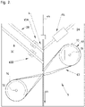
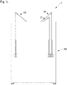
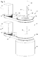
- FIGS. 1-4 show views of an embodiment of the system 1 according to the invention. Said system 1 is configured to perform the method according to the invention.
- the system 1 comprises a mandrel 4, a winding device 5 for helically winding strips 2 around the mandrel 4 to form a base tube 6 moving away from the mandrel 4 at a tube speed vt (meter/second), a strip suppling device 7 for supplying the strips 2 to the winding device 5, a cutting device 8 for cutting the base tube 6 at a predetermined length It to form the lengths of tube 3 while the base tube 6 is moving in a tube direction 9 at the tube speed vt, and a positioning device 80 for positioning the cut lengths of tube 3.
- the system 1 comprises a support frame 110.
- the supplying device 7 supplies a first strip 2A, a second strip 2B and a third strip 2C.
- the first strip 2A is moved along a wax unit 64 configured to provide a layer of wax onto a contact side of the first strip 2A.
- the layer of wax functions as a lubrication between the mandrel 4 and the first strip 2A.
- the second strip 2B and the third strip 2C are not in direct contact with the mandrel 4.
- the second strip 2B is moved along a first adhesive unit 65A to apply a layer of adhesive to the second strip 2B so that it will adhere to the first strip 2A.
- the third strip 2C is moved along a second adhesive unit 65B to apply a layer of adhesive to the third strip 2C so that it will adhere to the second strip 2B. This way the base tube 6 is formed.
- the first, second and third strips 2A-C are paper strips 2.
- the strip supplying device 7 is configured to supply only paper strips 2 and the winding device 5 is configured to helically wind the paper strips 2 around the mandrel 4.
- the strip supplying device 7 may be configured to (also) supply strips 2 made from a different material, such as one or more plastics.
- the mandrel 4 has an elongate form defining a longitudinal mandrel axis 44 extending in line with the tube direction 9.
- the winding device 5 comprises a first winding roller 61 and a second winding roller 62 located at opposite sides of the mandrel 4.
- the first winding roller 61 is rotatable about a first roller axis 71 and the second winding roller 62 is rotatable about a second roller axis 72.
- a winding belt 63 extends around the first winding roller 61 and the second winding roller 62.
- the winding belt 63 is wound around the mandrel 4.
- the winding device 5 comprises a winding drive 60 operatively coupled to the first winding roller 61 for rotation about the first roller axis 71 as shown by the first rotation arrow 73.
- the winding belt 63 will helically wind the strips 2 around the mandrel 4 to form the base tube 6 moving along and away from the mandrel 4 at the tube speed vt.
- the base tube 6 comprises a longitudinal tube axis 49. Due to the winding movement of winding belt 63, the base tube 6 rotates around its longitudinal tube axis 49.
- the system 1 comprises a controller 50 having a first communication connection 51 with the winding device 5, more specifically with the winding drive 60 of the winding device 5.
- the cutting device 8 comprises a knife displacement drive 42 and a knife rotation drive 35 (for more details see figure 5 ).
- the knife displacement drive 42 is connected to the controller 50 via a second communication connection 52.
- the knife rotation drive 35 is connected to the controller 50 via a third communication connection 53.
- the positioning device 80 comprises a positioning wheel 83 which is rotatable about a positioning axis 82 and configured to place a vertically extending length of tube 3 in a horizontal position.
- the positioning device 80 comprises a positioning drive 81 which is connected to the controller 50 via a fourth communication connection 54.
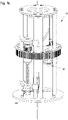
- the cutting device 8 is shown in detail in figure 5 .
- the base tube 6 enters the cutting device 8 via a support tube 89 while moving with the tube speed vt in the tube direction 9.
- the knife displacement drive 42 comprises a knife displacement gear wheel 45 which is operatively coupled with a knife displacement gear ring 38 via a knife displacement belt 46.
- the knife displacement gear ring 38 comprises first outer threads 37 (see also figure 6 ).
- the knife rotation drive 35 comprises a knife control gear wheel 47 which is operatively coupled with a knife control gear ring 36 via a knife control belt 48.
- the knife control gear ring 36 comprises second outer threads 39 (see also figure 6 ).
- the cutting device 8 comprises a cutting housing 100.
- the cutting housing 100 comprise a control housing part 97 and a knife housing part 99.
- the control housing part 97 is attached to the knife control gear ring 36 in order to rotate along with the knife control gear ring 36.
- the knife housing part 99 is not fixated to the knife control gear ring 36 or the control housing part 97, due to which the knife housing part 99 is able to rotate relative to the knife control gear ring 36 and the control housing part 97.
- the knife housing part 99 is attached to the knife displacement gear ring 38 in order to rotate along with the knife displacement gear ring 38.
- FIG 6 shows the inside of the cutting device 8.
- the knife housing part 99 has been removed and the knife control gear ring 36 and the control housing part 97 are shown in a cross sectional view.
- the cutting device 8 comprises four knives 10 which are movable along a knife trajectory 11 surrounding a centre axis 12 and extending over a knife axial distance d ak along the centre axis 12 (see also the figures 9 and 10 ).
- the cutting device 8 comprises only one knife or two, three or five or six knives 10.
- the knife trajectory 11 forms, when viewed in a direction 15 of the centre axis 12, a virtual circle 13 having a knife radius distance r k and a circle centre 14 coinciding with the centre axis 12 (see also figure 9A ).
- the knife trajectory 11 comprises a cutting part 17 in which the knives 10 are moved over the knife axial distance d ak in the tube direction 9 while, when viewed in the direction 15 of the centre axis 12, moving along the virtual circle 13.
- the knife trajectory 11 further comprises a retrieving part 18 in which the knives 10 are moved over the knife axial distance d ak and opposite to the tube direction 9 while, when viewed in the direction 15 of the centre axis 12, moving along the virtual circle 13 (see also figure 9B ).
- the cutting device 8 is configured to cut the base tube 6 with the knives 10 moving along the cutting part 17 of the knife trajectory 11 (see also the figures 12A and 12B ).
- the cutting device 8 comprises a first displacement unit 19 configured to displace the knives 10 around the centre axis 12 and, when viewed in the direction of centre axis 12, along the virtual circle 13 and a second displacement unit 20 configured to displace the knives 10 over the knife axial distance d ak in the tube direction 9 and opposite thereto.
- a knife displacement drive 42 which is operatively coupled to the first displacement unit 19 and the second displacement unit 20 and configured to move the knives 10, when viewed in the direction 15 of the centre axis 12, along the virtual circle 13 at a rotational knife speed ⁇ k (cycles/min) - see also figure 9A - and to move the knives 10 over at least part of the knife axial distance d ak in the tube direction 9 at an axial knife speed v k (meter/second) equal to the tube speed v t when the knives 10 move along the cutting part 17 of the knife trajectory 11 and cuts the base tube 6 (see also figure 13A ).
- the configuration of the cutting device 8 allows that the cutting device 8 creates a relatively more accurate cut in the base tube 6.
- the configuration of the cutting device 8 also allows that the cutting device 8 operates at a relatively higher speed.
- the knives 10 have the function of acting as counterweights 40.
- the cutting device 8 may comprise a different type of counterweight 40 which is movable along the knife trajectory 11 or at a counterweight 40 trajectory at a constant counterweight 40 distance from the knife trajectory 11 to balance the movement of the knives 10 along the trajectory.
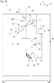
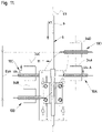
- Figure 16 shows the inside of a cutting device 8 of an alternative embodiment of the system 1. It differs from the embodiment of the figure 1-14 in that the cutting device 8 comprises only one knife and one counterweight 40 (not being a knife).
- the first displacement unit 19 and the second displacement unit 20 are configured to continuously displace a same number of knives 10 along the cutting part 17 of the knife trajectory 11 as displaced along the retrieving part 18 of the knife trajectory 11.
- the first displacement unit 19 comprises knife supports 29 holding the knives 10 at the knife radius distance r k from the centre axis 12, while allowing movement of the knives 10 over the knife axial distance d ak parallel to the centre axis 12.
- the first displacement unit 19 is configured to rotate the knife supports 29 around the centre axis 12, while holding the knives 10 at the knife radius distance r k from the centre axis 12.
- the knife supports 29 are attached to the knife displacement gear ring 38 to move along with the knife displacement gear ring 38.
- Each knife support comprises two support beams 90 extending parallel to the centre axis 12 and a knife slider 91 which is movable along the support beams 90.
- the knives 10 are rotatably attached to the knife sliders 91 via a rotation beam 92.
- the second displacement unit 20 comprises cams 31 attached to the knives 10 and a cam track 32 configured to displace the knives 10 over the knife axial distance d ak parallel to the centre axis 12 in the tube direction 9 when the knives 10 move along the cutting part 17 of the knife trajectory 11 and to move the knives 10 over the knife axial distance d ak parallel to the centre axis 12 and opposite to the tube direction 9 when the knives 10 move along the retrieving part 18 of the knife trajectory 11.
- the cam track 32 is shown in more detail in figure 8 .
- the knives 10 are rotating knives 33 having a rotation axis 34 extending parallel to the centre axis 12.
- the knives 10 are operatively attached to a knife rotation gearwheel 93 surrounding the rotation axis 34.
- the cutting device 8 comprises a knife rotation gear ring 94 engaging the knife rotation gearwheels 93 of the knives 10 and having a knife rotation ring centre 98 coinciding with the centre axis 12.
- the knife rotation gear ring 94 comprises inner threads 95.
- the knife rotation gear wheels 93 and the knife rotation gear ring 94 cooperate to rotate the knives 10 about their rotation axis 34 when the knives 10 are, when viewed in the direction 15 of the centre axis 12, moved along the virtual circle 13.
- the knife rotation gear ring 94 is rotatable about the knife rotation ring centre 98 and the cutting device 8 comprises a knife rotation drive 35 configured to rotate the knife rotation gear ring 94 about the knife rotation ring centre 98 in order to adjust a rotational cutting speed ⁇ c (cycles/minute) with which the knives 10 rotate around their rotation axis 34.
- the knife rotation gear ring 94 is attached to the control housing part 97 in order to move along with the control housing part 97. This way, the control housing part 97 has the function of a control connector 96 which operatively couples the knife rotation gear ring 94 and the knife control gear ring 36 driven by the knife rotation drive 35.
- the knife rotation gear ring 94 is shown in more detail in figure 7 .
- the controller 50 is connected with the knife rotation drive 35 via the third communication connection 53.
- the controller 50 is configured to control the rotational cutting speed ⁇ c with which the knives 10 rotate around their rotation axis 34 by adjusting the rotation of the knife rotation gear ring 94 about the knife rotation ring centre 98.
- the controller 50 is connected to the winding device 5 via the first communication connection 51 and to the knife displacement drive 42 via the second communication connection 52.
- the controller 50 is configured to control the tube speed vt with which the base tube 6 moves away from the mandrel 4 and the rotational knife speed ⁇ k with which the knife is, when viewed in direction 15 of the centre axis 12, moved along the virtual circle 13.
- the predetermined length l t of the lengths of tube 3 produced by the system 1 is determined by the tube speed v t with which the base tube 6 moves away from the mandrel 4 and the rotational knife speed ⁇ k with which the knife is, when viewed in direction 15 of the centre axis 12, moved along the virtual circle 13.
- the system will operate in practice with a constant tube speed vt and knife speed ⁇ k .
- Figure 9A shows a top view in the direction 15 of the centre axis 12 of the knives 10 and the tube support 41 of the cutting device 8 shown in figure 5 .
- Figure 9B shows the top view of figure 9A without the tube support 41.
- Figure 10 shows a side view of the knives 10 and the tube support 41 of figure 9A .
- Figure 11 shows a further side view of the knives 10 and the tube support 41 of figure 9A .
- the tube support 41 is configured to hold the base tube 6 in the knife trajectory 11.
- the tube direction 9 extends parallel to the centre axis 12.
- the longitudinal tube axis 49 of the base tube 6 extends parallel to the centre axis 12.
- the cutting part 17 of the knife trajectory 11 starts at a cutting part starting position 21 on the knife trajectory 11 and ends at a cutting part ending position 22 on the knife trajectory 11.
- the retrieving part 18 of the retrieving trajectory starts at a retrieving part starting position 23 on the knife trajectory 11 and ends at a retrieving part ending position 24 on the knife trajectory 11.
- the retrieving part ending position 24 and cutting part starting position 21 coincide, and the cutting part ending position 22 and the retrieving part starting position 23 coincide.
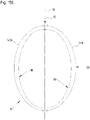
- the knife trajectory 11 has, when viewed in a transverse direction 16 extending perpendicular to the centre axis 12, an oval-like shape.
- the knives 10 are, when viewed in the direction 15 of the centre axis 12, located at an equal distance d ck from each other along the virtual circle 13.
- the cutting part 17 and the retrieving part 18 of the knife trajectory 11 are, when viewed in the direction 15 of the centre axis 12, located at opposite sides of the virtual circle 13.
- the cutting part 17 of the knife trajectory 11 has a cutting part length l cp
- the retrieving part 18 of the knife trajectory 11 has a retrieving part length l rp
- the retrieving part length l rp is equal to the cutting part length l rp .
- the fourth knife 10D is about to start to move along the cutting part 17 of the knife trajectory 11 and has an axial knife speed v k-a equal to the tube speed v t and in the tube direction 9.
- the first knife 10A is located halfway the cutting part 17 of the knife trajectory 11.
- the second knife 10B is about to start to move along the retrieving part 18 of the knife trajectory 11.
- the third knife 10C is located halfway the retrieving part 18 of the knife trajectory 11.
- the third knife 10C is located halfway the retrieving part 18 of the knife trajectory 11 and has an axial knife speed v k-c equal to the tube speed vt and opposite to the tube direction 9.
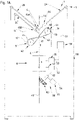
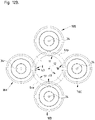
- Figure 12A shows a further top view in the direction 15 of the centre axis 12 of the knives 10 and tube support 41 of the cutting device 8 of figure 5 .
- Figure 12B shows the top view of figure 12A without the tube support 41.
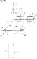
- Figure 13A shows a side view of the knives 10 and tube support 41 of figure 12A .
- Figure 13B shows the side view of figure 13A without the tube support 41.
- Figure 14A shows a further side view of the knives 10 and tube support 41 of figure 12A .
- Figure 14B shows the side view of figure 14A without the tube support 41.
- the knives 10 are moved a bit further along the knife trajectory 11 when compared with the figures 9-11 .
- the first knife 10A is moving along the cutting part 17 of the knife trajectory 11 and is located closer to the cutting part ending position 22 than to the cutting part starting position 21.
- the first knife 10A is cutting the base tube 6 and extends through part of the base tube 6. In other words, the first knife 10A is moved through part of the base tube 6. More specifically, a cutting area 43 of the first knife 10A is moved through part of the base tube 6. Since the winding device 5 is configured to rotate the base tube 6 around the mandrel 4, the base tube 6 rotates around its longitudinal tube axis 49.
- the first knife 10A extending through part of the base tube 6 creates a complete cut separating a length of tube 3 having a predetermined length l t from the base tube 6.
- the first knife 10A has an axial knife speed v k-a equal to the tube speed vt and in the tube direction 9. This means that when the first knife 10A is cutting the base tube 6, the first knife 10A and the base tube 6 have the same speed in the tube direction 9. This ensures that the first knife 10A creates an accurate cut, even though the first knife 10A during the cutting of the base tube 6 also moves, when viewed in the direction 15 of the centre axis 12, along the virtual circle 13 at the rotational knife speed ⁇ k .
- the second knife 10B is moving along the retrieving part 18 of the knife trajectory 11 and is located closer to the retrieving part starting position 23 than to the retrieving part ending position 24.
- the third knife 10C is moving along the retrieving part 18 of the knife trajectory 11 and is located closer to the retrieving part ending position 24 than to the retrieving part starting position 23.
- the fourth knife 10D is moving along the cutting part 17 of the knife trajectory 11 and is located closer to the cutting part starting position 21 than to the cutting part ending position 22.
- the first knife 10A and the fourth knife 10D have an axial knife speed v k-a , v k-d equal to the tube speed v t and in the tube direction 9.
- the second knife 10B and the third knife 10C have an axial knife speed v k-b , v k-c equal to the tube speed vt and opposite to the tube direction 9. All the knives 10 move, when viewed in the direction 15 of the centre axis 12, along the virtual circle 13 at the rotational knife speed ⁇ k .
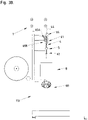
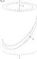
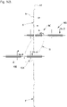
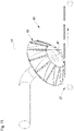
- Figure 15A shows a view in perspective of the knife trajectory 11 of the cutting device 8 of figure 5 .
- the figures 15B and 15C show side views of the knife trajectory 11.
- Figure 15B shows a side view in the direction of the arrow 26 shown in figure 15C.
- Figure 15C shows a side view in the direction of the arrow 16 shown in the figures 9B and 15B .
- Figure 16 shows an alternative embodiment of the system 1 according to the invention.
- the cutting device 8 comprises only one knife 10 and one counterweight 40 not being a knife.
- Figure 17 shows a view in perspective of the positioning device of the system of figure 1 .
- the positioning device 80 is configured to position the cut lengths of tube 3 in a horizontal position.
- the positioning wheel 83 receives the cut lengths of tube 3 and rotates them in a horizontal position on a conveyor belt 27.
Landscapes
- Life Sciences & Earth Sciences (AREA)
- Forests & Forestry (AREA)
- Engineering & Computer Science (AREA)
- Mechanical Engineering (AREA)
- Making Paper Articles (AREA)
- Shaping Of Tube Ends By Bending Or Straightening (AREA)
- Rigid Pipes And Flexible Pipes (AREA)
- Auxiliary Devices For And Details Of Packaging Control (AREA)
Applications Claiming Priority (2)
| Application Number | Priority Date | Filing Date | Title |
|---|---|---|---|
| NL2021979A NL2021979B1 (en) | 2018-11-12 | 2018-11-12 | System for producing lengths of tube comprising helically wound strips |
| PCT/EP2019/080939 WO2020099361A1 (en) | 2018-11-12 | 2019-11-12 | System for producing lengths of tube comprising helically wound strips |
Publications (2)
| Publication Number | Publication Date |
|---|---|
| EP3880457A1 EP3880457A1 (en) | 2021-09-22 |
| EP3880457B1 true EP3880457B1 (en) | 2022-11-02 |
Family
ID=65409431
Family Applications (1)
| Application Number | Title | Priority Date | Filing Date |
|---|---|---|---|
| EP19798658.1A Active EP3880457B1 (en) | 2018-11-12 | 2019-11-12 | System for producing lengths of tube comprising helically wound strips |
Country Status (9)
| Country | Link |
|---|---|
| US (1) | US11660772B2 (pt) |
| EP (1) | EP3880457B1 (pt) |
| CA (1) | CA3119077A1 (pt) |
| ES (1) | ES2937444T3 (pt) |
| LT (1) | LT3880457T (pt) |
| NL (1) | NL2021979B1 (pt) |
| PL (1) | PL3880457T3 (pt) |
| PT (1) | PT3880457T (pt) |
| WO (1) | WO2020099361A1 (pt) |
Families Citing this family (3)
| Publication number | Priority date | Publication date | Assignee | Title |
|---|---|---|---|---|
| EP3981584A1 (en) | 2020-10-12 | 2022-04-13 | International Tobacco Machinery Poland SP. Z O.O. | Apparatus and method for manufacturing of spirally wound tubes |
| EP3981586A1 (en) | 2020-10-12 | 2022-04-13 | International Tobacco Machinery Poland SP. Z O.O. | Drive unit and apparatus for manufacturing of spiral tubes |
| EP4588651A1 (en) | 2024-01-18 | 2025-07-23 | International Tobacco Machinery Poland Sp. z o.o. | Method and apparatus for manufacturing spiral paper tubes composed of at least two strands of material |
Family Cites Families (6)
| Publication number | Priority date | Publication date | Assignee | Title |
|---|---|---|---|---|
| US1242478A (en) * | 1915-08-09 | 1917-10-09 | Homer J Young | Cutter-head for cigarette-machines. |
| US3942418A (en) * | 1975-03-21 | 1976-03-09 | Container Corporation Of America | Apparatus for helically winding container bodies |
| US4370140A (en) * | 1979-03-28 | 1983-01-25 | Paco Winders, Inc. | Paper tube cut off saw |
| IT1213652B (it) * | 1987-07-22 | 1989-12-29 | Gd Spa | Dispositivo per il taglio trasversale in spezzoni di un nastro mobile di moto continuo lungo un percorso determinato |
| TWI656020B (zh) * | 2014-09-02 | 2019-04-11 | 義大利商莫托雷斯紙業責任有限公司 | 用於藉由將帶狀材料捲繞一成型心軸來生產管體的機器 |
| US11117343B2 (en) * | 2019-08-15 | 2021-09-14 | Hoffmaster Group, Inc. | System and method for cutting straws |
-
2018
- 2018-11-12 NL NL2021979A patent/NL2021979B1/en active
-
2019
- 2019-11-12 PT PT197986581T patent/PT3880457T/pt unknown
- 2019-11-12 CA CA3119077A patent/CA3119077A1/en active Pending
- 2019-11-12 ES ES19798658T patent/ES2937444T3/es active Active
- 2019-11-12 LT LTEPPCT/EP2019/080939T patent/LT3880457T/lt unknown
- 2019-11-12 PL PL19798658.1T patent/PL3880457T3/pl unknown
- 2019-11-12 US US17/292,942 patent/US11660772B2/en active Active
- 2019-11-12 WO PCT/EP2019/080939 patent/WO2020099361A1/en not_active Ceased
- 2019-11-12 EP EP19798658.1A patent/EP3880457B1/en active Active
Also Published As
| Publication number | Publication date |
|---|---|
| LT3880457T (lt) | 2023-03-27 |
| US11660772B2 (en) | 2023-05-30 |
| CA3119077A1 (en) | 2020-05-22 |
| WO2020099361A1 (en) | 2020-05-22 |
| NL2021979B1 (en) | 2020-05-15 |
| EP3880457A1 (en) | 2021-09-22 |
| PL3880457T3 (pl) | 2023-03-20 |
| US20220001564A1 (en) | 2022-01-06 |
| PT3880457T (pt) | 2023-01-26 |
| ES2937444T3 (es) | 2023-03-28 |
Similar Documents
| Publication | Publication Date | Title |
|---|---|---|
| EP3880457B1 (en) | System for producing lengths of tube comprising helically wound strips | |
| JP3276979B2 (ja) | ウェブ巻取り装置およびウェブ巻取り方法 | |
| US9199388B2 (en) | System for finishing printed labels using multiple X-Y cutters | |
| US6260786B1 (en) | Winder for sheet material | |
| EP0264244A2 (en) | Apparatus for manufacturing a resin tube | |
| EP2246160B1 (de) | Vorrichtung und Verfahren zum Schneiden von bahn- oder bogenförmigem, für Luft durchlässigem Gewebe- oder Vliesmaterial | |
| CN112978469A (zh) | 一种高分子薄膜生产分切工艺 | |
| DE602004013241T2 (de) | Wechselvorrichtung and Verfahren zum Wechseln des Aufwickelns einer Bahn | |
| CA3118982A1 (en) | System for producing lengths of tube comprising helically wound strips | |
| CA2010755C (en) | Running circular pipe cutting device | |
| US3481234A (en) | Recutting of cylindrical tubes into a plurality of tubes | |
| CN109227675A (zh) | 一种自动化金属件加工装置 | |
| US3630126A (en) | Apparatus for cutting tubes | |
| CN109311192A (zh) | 砑光设施和用于使塑料膜光滑的方法 | |
| US5791587A (en) | Apparatus and method for transferring a feeding web from a filled takeup core to an empty takeup core | |
| CN223419709U (zh) | 一种分切机 | |
| JP4472071B2 (ja) | 絞り加工装置 | |
| CN219132564U (zh) | 裁切机 | |
| CN222082057U (zh) | 一种pe薄膜生产用切边回收装置 | |
| CN214271436U (zh) | 一种激光照排自动面料裁剪系统 | |
| JP4708331B2 (ja) | 複数のストリップに横方向のミシン目を開けるための装置及び方法 | |
| JPH09267415A (ja) | 蛇行追従機能を有する帯状物加工装置 | |
| CN207973921U (zh) | 一种导布机 | |
| CN118753881A (zh) | 一种布匹连续收卷装置及收卷方法 | |
| JP2006224264A (ja) | 芯材に巻かれた樹脂フィルムロールの切断装置 |
Legal Events
| Date | Code | Title | Description |
|---|---|---|---|
| STAA | Information on the status of an ep patent application or granted ep patent |
Free format text: STATUS: UNKNOWN |
|
| STAA | Information on the status of an ep patent application or granted ep patent |
Free format text: STATUS: THE INTERNATIONAL PUBLICATION HAS BEEN MADE |
|
| PUAI | Public reference made under article 153(3) epc to a published international application that has entered the european phase |
Free format text: ORIGINAL CODE: 0009012 |
|
| STAA | Information on the status of an ep patent application or granted ep patent |
Free format text: STATUS: REQUEST FOR EXAMINATION WAS MADE |
|
| 17P | Request for examination filed |
Effective date: 20210519 |
|
| AK | Designated contracting states |
Kind code of ref document: A1 Designated state(s): AL AT BE BG CH CY CZ DE DK EE ES FI FR GB GR HR HU IE IS IT LI LT LU LV MC MK MT NL NO PL PT RO RS SE SI SK SM TR |
|
| DAV | Request for validation of the european patent (deleted) | ||
| DAX | Request for extension of the european patent (deleted) | ||
| GRAP | Despatch of communication of intention to grant a patent |
Free format text: ORIGINAL CODE: EPIDOSNIGR1 |
|
| STAA | Information on the status of an ep patent application or granted ep patent |
Free format text: STATUS: GRANT OF PATENT IS INTENDED |
|
| RIC1 | Information provided on ipc code assigned before grant |
Ipc: B26D 3/16 20060101ALI20220505BHEP Ipc: B26D 1/62 20060101ALI20220505BHEP Ipc: B26D 1/60 20060101ALI20220505BHEP Ipc: B31C 11/00 20060101ALI20220505BHEP Ipc: B31C 3/00 20060101AFI20220505BHEP |
|
| INTG | Intention to grant announced |
Effective date: 20220525 |
|
| GRAS | Grant fee paid |
Free format text: ORIGINAL CODE: EPIDOSNIGR3 |
|
| GRAA | (expected) grant |
Free format text: ORIGINAL CODE: 0009210 |
|
| STAA | Information on the status of an ep patent application or granted ep patent |
Free format text: STATUS: THE PATENT HAS BEEN GRANTED |
|
| AK | Designated contracting states |
Kind code of ref document: B1 Designated state(s): AL AT BE BG CH CY CZ DE DK EE ES FI FR GB GR HR HU IE IS IT LI LT LU LV MC MK MT NL NO PL PT RO RS SE SI SK SM TR |
|
| RAP3 | Party data changed (applicant data changed or rights of an application transferred) |
Owner name: IMATEC - INNOVATIVE MACHINE TECHNOLOGY S.A.R.L. |
|
| REG | Reference to a national code |
Ref country code: GB Ref legal event code: FG4D |
|
| REG | Reference to a national code |
Ref country code: CH Ref legal event code: EP Ref country code: AT Ref legal event code: REF Ref document number: 1528470 Country of ref document: AT Kind code of ref document: T Effective date: 20221115 |
|
| REG | Reference to a national code |
Ref country code: DE Ref legal event code: R096 Ref document number: 602019021516 Country of ref document: DE |
|
| REG | Reference to a national code |
Ref country code: IE Ref legal event code: FG4D |
|
| REG | Reference to a national code |
Ref country code: RO Ref legal event code: EPE |
|
| REG | Reference to a national code |
Ref country code: PT Ref legal event code: SC4A Ref document number: 3880457 Country of ref document: PT Date of ref document: 20230126 Kind code of ref document: T Free format text: AVAILABILITY OF NATIONAL TRANSLATION Effective date: 20230120 |
|
| REG | Reference to a national code |
Ref country code: NL Ref legal event code: FP |
|
| REG | Reference to a national code |
Ref country code: SE Ref legal event code: TRGR |
|
| REG | Reference to a national code |
Ref country code: GR Ref legal event code: EP Ref document number: 20230400175 Country of ref document: GR Effective date: 20230307 |
|
| REG | Reference to a national code |
Ref country code: ES Ref legal event code: FG2A Ref document number: 2937444 Country of ref document: ES Kind code of ref document: T3 Effective date: 20230328 |
|
| REG | Reference to a national code |
Ref country code: AT Ref legal event code: MK05 Ref document number: 1528470 Country of ref document: AT Kind code of ref document: T Effective date: 20221102 |
|
| PG25 | Lapsed in a contracting state [announced via postgrant information from national office to epo] |
Ref country code: NO Free format text: LAPSE BECAUSE OF FAILURE TO SUBMIT A TRANSLATION OF THE DESCRIPTION OR TO PAY THE FEE WITHIN THE PRESCRIBED TIME-LIMIT Effective date: 20230202 Ref country code: FI Free format text: LAPSE BECAUSE OF FAILURE TO SUBMIT A TRANSLATION OF THE DESCRIPTION OR TO PAY THE FEE WITHIN THE PRESCRIBED TIME-LIMIT Effective date: 20221102 Ref country code: AT Free format text: LAPSE BECAUSE OF FAILURE TO SUBMIT A TRANSLATION OF THE DESCRIPTION OR TO PAY THE FEE WITHIN THE PRESCRIBED TIME-LIMIT Effective date: 20221102 |
|
| PG25 | Lapsed in a contracting state [announced via postgrant information from national office to epo] |
Ref country code: RS Free format text: LAPSE BECAUSE OF FAILURE TO SUBMIT A TRANSLATION OF THE DESCRIPTION OR TO PAY THE FEE WITHIN THE PRESCRIBED TIME-LIMIT Effective date: 20221102 Ref country code: LV Free format text: LAPSE BECAUSE OF FAILURE TO SUBMIT A TRANSLATION OF THE DESCRIPTION OR TO PAY THE FEE WITHIN THE PRESCRIBED TIME-LIMIT Effective date: 20221102 Ref country code: IS Free format text: LAPSE BECAUSE OF FAILURE TO SUBMIT A TRANSLATION OF THE DESCRIPTION OR TO PAY THE FEE WITHIN THE PRESCRIBED TIME-LIMIT Effective date: 20230302 Ref country code: HR Free format text: LAPSE BECAUSE OF FAILURE TO SUBMIT A TRANSLATION OF THE DESCRIPTION OR TO PAY THE FEE WITHIN THE PRESCRIBED TIME-LIMIT Effective date: 20221102 |
|
| P01 | Opt-out of the competence of the unified patent court (upc) registered |
Effective date: 20230522 |
|
| PG25 | Lapsed in a contracting state [announced via postgrant information from national office to epo] |
Ref country code: SM Free format text: LAPSE BECAUSE OF FAILURE TO SUBMIT A TRANSLATION OF THE DESCRIPTION OR TO PAY THE FEE WITHIN THE PRESCRIBED TIME-LIMIT Effective date: 20221102 Ref country code: EE Free format text: LAPSE BECAUSE OF FAILURE TO SUBMIT A TRANSLATION OF THE DESCRIPTION OR TO PAY THE FEE WITHIN THE PRESCRIBED TIME-LIMIT Effective date: 20221102 Ref country code: DK Free format text: LAPSE BECAUSE OF FAILURE TO SUBMIT A TRANSLATION OF THE DESCRIPTION OR TO PAY THE FEE WITHIN THE PRESCRIBED TIME-LIMIT Effective date: 20221102 Ref country code: CZ Free format text: LAPSE BECAUSE OF FAILURE TO SUBMIT A TRANSLATION OF THE DESCRIPTION OR TO PAY THE FEE WITHIN THE PRESCRIBED TIME-LIMIT Effective date: 20221102 Ref country code: IT Free format text: LAPSE BECAUSE OF NON-PAYMENT OF DUE FEES Effective date: 20221112 |
|
| REG | Reference to a national code |
Ref country code: DE Ref legal event code: R097 Ref document number: 602019021516 Country of ref document: DE |
|
| PG25 | Lapsed in a contracting state [announced via postgrant information from national office to epo] |
Ref country code: SK Free format text: LAPSE BECAUSE OF FAILURE TO SUBMIT A TRANSLATION OF THE DESCRIPTION OR TO PAY THE FEE WITHIN THE PRESCRIBED TIME-LIMIT Effective date: 20221102 Ref country code: AL Free format text: LAPSE BECAUSE OF FAILURE TO SUBMIT A TRANSLATION OF THE DESCRIPTION OR TO PAY THE FEE WITHIN THE PRESCRIBED TIME-LIMIT Effective date: 20221102 |
|
| PLBE | No opposition filed within time limit |
Free format text: ORIGINAL CODE: 0009261 |
|
| STAA | Information on the status of an ep patent application or granted ep patent |
Free format text: STATUS: NO OPPOSITION FILED WITHIN TIME LIMIT |
|
| 26N | No opposition filed |
Effective date: 20230803 |
|
| PG25 | Lapsed in a contracting state [announced via postgrant information from national office to epo] |
Ref country code: IE Free format text: LAPSE BECAUSE OF NON-PAYMENT OF DUE FEES Effective date: 20221112 |
|
| PG25 | Lapsed in a contracting state [announced via postgrant information from national office to epo] |
Ref country code: SI Free format text: LAPSE BECAUSE OF FAILURE TO SUBMIT A TRANSLATION OF THE DESCRIPTION OR TO PAY THE FEE WITHIN THE PRESCRIBED TIME-LIMIT Effective date: 20221102 |
|
| PG25 | Lapsed in a contracting state [announced via postgrant information from national office to epo] |
Ref country code: IT Free format text: LAPSE BECAUSE OF NON-PAYMENT OF DUE FEES Effective date: 20221112 |
|
| PGRI | Patent reinstated in contracting state [announced from national office to epo] |
Ref country code: IT Effective date: 20221130 |
|
| PG25 | Lapsed in a contracting state [announced via postgrant information from national office to epo] |
Ref country code: CY Free format text: LAPSE BECAUSE OF FAILURE TO SUBMIT A TRANSLATION OF THE DESCRIPTION OR TO PAY THE FEE WITHIN THE PRESCRIBED TIME-LIMIT Effective date: 20221102 |
|
| PG25 | Lapsed in a contracting state [announced via postgrant information from national office to epo] |
Ref country code: MK Free format text: LAPSE BECAUSE OF FAILURE TO SUBMIT A TRANSLATION OF THE DESCRIPTION OR TO PAY THE FEE WITHIN THE PRESCRIBED TIME-LIMIT Effective date: 20221102 Ref country code: HU Free format text: LAPSE BECAUSE OF FAILURE TO SUBMIT A TRANSLATION OF THE DESCRIPTION OR TO PAY THE FEE WITHIN THE PRESCRIBED TIME-LIMIT; INVALID AB INITIO Effective date: 20191112 |
|
| PG25 | Lapsed in a contracting state [announced via postgrant information from national office to epo] |
Ref country code: MC Free format text: LAPSE BECAUSE OF FAILURE TO SUBMIT A TRANSLATION OF THE DESCRIPTION OR TO PAY THE FEE WITHIN THE PRESCRIBED TIME-LIMIT Effective date: 20221102 |
|
| PG25 | Lapsed in a contracting state [announced via postgrant information from national office to epo] |
Ref country code: MC Free format text: LAPSE BECAUSE OF FAILURE TO SUBMIT A TRANSLATION OF THE DESCRIPTION OR TO PAY THE FEE WITHIN THE PRESCRIBED TIME-LIMIT Effective date: 20221102 |
|
| PG25 | Lapsed in a contracting state [announced via postgrant information from national office to epo] |
Ref country code: MT Free format text: LAPSE BECAUSE OF FAILURE TO SUBMIT A TRANSLATION OF THE DESCRIPTION OR TO PAY THE FEE WITHIN THE PRESCRIBED TIME-LIMIT Effective date: 20221102 |
|
| REG | Reference to a national code |
Ref country code: CH Ref legal event code: U11 Free format text: ST27 STATUS EVENT CODE: U-0-0-U10-U11 (AS PROVIDED BY THE NATIONAL OFFICE) Effective date: 20251201 |
|
| PGFP | Annual fee paid to national office [announced via postgrant information from national office to epo] |
Ref country code: PT Payment date: 20251029 Year of fee payment: 7 |
|
| PGFP | Annual fee paid to national office [announced via postgrant information from national office to epo] |
Ref country code: NL Payment date: 20251124 Year of fee payment: 7 Ref country code: LU Payment date: 20251124 Year of fee payment: 7 |
|
| PGFP | Annual fee paid to national office [announced via postgrant information from national office to epo] |
Ref country code: DE Payment date: 20251118 Year of fee payment: 7 |
|
| PGFP | Annual fee paid to national office [announced via postgrant information from national office to epo] |
Ref country code: LT Payment date: 20251030 Year of fee payment: 7 Ref country code: GB Payment date: 20251120 Year of fee payment: 7 |
|
| PGFP | Annual fee paid to national office [announced via postgrant information from national office to epo] |
Ref country code: IT Payment date: 20251128 Year of fee payment: 7 |
|
| PGFP | Annual fee paid to national office [announced via postgrant information from national office to epo] |
Ref country code: FR Payment date: 20251120 Year of fee payment: 7 |
|
| PGFP | Annual fee paid to national office [announced via postgrant information from national office to epo] |
Ref country code: TR Payment date: 20251107 Year of fee payment: 7 Ref country code: GR Payment date: 20251117 Year of fee payment: 7 Ref country code: BE Payment date: 20251124 Year of fee payment: 7 |
|
| PGFP | Annual fee paid to national office [announced via postgrant information from national office to epo] |
Ref country code: CH Payment date: 20251201 Year of fee payment: 7 Ref country code: SE Payment date: 20251119 Year of fee payment: 7 |
|
| PGFP | Annual fee paid to national office [announced via postgrant information from national office to epo] |
Ref country code: PL Payment date: 20251103 Year of fee payment: 7 Ref country code: BG Payment date: 20251114 Year of fee payment: 7 |
|
| PGFP | Annual fee paid to national office [announced via postgrant information from national office to epo] |
Ref country code: RO Payment date: 20251107 Year of fee payment: 7 |
|
| PGFP | Annual fee paid to national office [announced via postgrant information from national office to epo] |
Ref country code: ES Payment date: 20251216 Year of fee payment: 7 |