EP3883449B1 - Bifunktionaler intubierender und beatmender supraglottischer luftweg - Google Patents
Bifunktionaler intubierender und beatmender supraglottischer luftweg Download PDFInfo
- Publication number
- EP3883449B1 EP3883449B1 EP19886982.8A EP19886982A EP3883449B1 EP 3883449 B1 EP3883449 B1 EP 3883449B1 EP 19886982 A EP19886982 A EP 19886982A EP 3883449 B1 EP3883449 B1 EP 3883449B1
- Authority
- EP
- European Patent Office
- Prior art keywords
- supraglottic
- ventilating
- bowl
- fluid flow
- intubation conduit
- Prior art date
- Legal status (The legal status is an assumption and is not a legal conclusion. Google has not performed a legal analysis and makes no representation as to the accuracy of the status listed.)
- Active
Links
Images





Classifications
-
- A—HUMAN NECESSITIES
- A61—MEDICAL OR VETERINARY SCIENCE; HYGIENE
- A61M—DEVICES FOR INTRODUCING MEDIA INTO, OR ONTO, THE BODY; DEVICES FOR TRANSDUCING BODY MEDIA OR FOR TAKING MEDIA FROM THE BODY; DEVICES FOR PRODUCING OR ENDING SLEEP OR STUPOR
- A61M16/00—Devices for influencing the respiratory system of patients by gas treatment, e.g. ventilators; Tracheal tubes
- A61M16/04—Tracheal tubes
- A61M16/0488—Mouthpieces; Means for guiding, securing or introducing the tubes
-
- A—HUMAN NECESSITIES
- A61—MEDICAL OR VETERINARY SCIENCE; HYGIENE
- A61M—DEVICES FOR INTRODUCING MEDIA INTO, OR ONTO, THE BODY; DEVICES FOR TRANSDUCING BODY MEDIA OR FOR TAKING MEDIA FROM THE BODY; DEVICES FOR PRODUCING OR ENDING SLEEP OR STUPOR
- A61M16/00—Devices for influencing the respiratory system of patients by gas treatment, e.g. ventilators; Tracheal tubes
- A61M16/04—Tracheal tubes
- A61M16/0402—Special features for tracheal tubes not otherwise provided for
-
- A—HUMAN NECESSITIES
- A61—MEDICAL OR VETERINARY SCIENCE; HYGIENE
- A61M—DEVICES FOR INTRODUCING MEDIA INTO, OR ONTO, THE BODY; DEVICES FOR TRANSDUCING BODY MEDIA OR FOR TAKING MEDIA FROM THE BODY; DEVICES FOR PRODUCING OR ENDING SLEEP OR STUPOR
- A61M16/00—Devices for influencing the respiratory system of patients by gas treatment, e.g. ventilators; Tracheal tubes
- A61M16/04—Tracheal tubes
- A61M16/0402—Special features for tracheal tubes not otherwise provided for
- A61M16/0409—Special features for tracheal tubes not otherwise provided for with mean for closing the oesophagus
-
- A—HUMAN NECESSITIES
- A61—MEDICAL OR VETERINARY SCIENCE; HYGIENE
- A61M—DEVICES FOR INTRODUCING MEDIA INTO, OR ONTO, THE BODY; DEVICES FOR TRANSDUCING BODY MEDIA OR FOR TAKING MEDIA FROM THE BODY; DEVICES FOR PRODUCING OR ENDING SLEEP OR STUPOR
- A61M16/00—Devices for influencing the respiratory system of patients by gas treatment, e.g. ventilators; Tracheal tubes
- A61M16/04—Tracheal tubes
- A61M16/0402—Special features for tracheal tubes not otherwise provided for
- A61M16/0415—Special features for tracheal tubes not otherwise provided for with access means to the stomach
-
- A—HUMAN NECESSITIES
- A61—MEDICAL OR VETERINARY SCIENCE; HYGIENE
- A61M—DEVICES FOR INTRODUCING MEDIA INTO, OR ONTO, THE BODY; DEVICES FOR TRANSDUCING BODY MEDIA OR FOR TAKING MEDIA FROM THE BODY; DEVICES FOR PRODUCING OR ENDING SLEEP OR STUPOR
- A61M16/00—Devices for influencing the respiratory system of patients by gas treatment, e.g. ventilators; Tracheal tubes
- A61M16/04—Tracheal tubes
- A61M16/0486—Multi-lumen tracheal tubes
-
- A—HUMAN NECESSITIES
- A61—MEDICAL OR VETERINARY SCIENCE; HYGIENE
- A61M—DEVICES FOR INTRODUCING MEDIA INTO, OR ONTO, THE BODY; DEVICES FOR TRANSDUCING BODY MEDIA OR FOR TAKING MEDIA FROM THE BODY; DEVICES FOR PRODUCING OR ENDING SLEEP OR STUPOR
- A61M16/00—Devices for influencing the respiratory system of patients by gas treatment, e.g. ventilators; Tracheal tubes
- A61M16/04—Tracheal tubes
- A61M16/0434—Cuffs
-
- A—HUMAN NECESSITIES
- A61—MEDICAL OR VETERINARY SCIENCE; HYGIENE
- A61M—DEVICES FOR INTRODUCING MEDIA INTO, OR ONTO, THE BODY; DEVICES FOR TRANSDUCING BODY MEDIA OR FOR TAKING MEDIA FROM THE BODY; DEVICES FOR PRODUCING OR ENDING SLEEP OR STUPOR
- A61M16/00—Devices for influencing the respiratory system of patients by gas treatment, e.g. ventilators; Tracheal tubes
- A61M16/08—Bellows; Connecting tubes ; Water traps; Patient circuits
- A61M16/0816—Joints or connectors
-
- A—HUMAN NECESSITIES
- A61—MEDICAL OR VETERINARY SCIENCE; HYGIENE
- A61M—DEVICES FOR INTRODUCING MEDIA INTO, OR ONTO, THE BODY; DEVICES FOR TRANSDUCING BODY MEDIA OR FOR TAKING MEDIA FROM THE BODY; DEVICES FOR PRODUCING OR ENDING SLEEP OR STUPOR
- A61M16/00—Devices for influencing the respiratory system of patients by gas treatment, e.g. ventilators; Tracheal tubes
- A61M16/20—Valves specially adapted to medical respiratory devices
- A61M16/208—Non-controlled one-way valves, e.g. exhalation, check, pop-off non-rebreathing valves
-
- A—HUMAN NECESSITIES
- A61—MEDICAL OR VETERINARY SCIENCE; HYGIENE
- A61M—DEVICES FOR INTRODUCING MEDIA INTO, OR ONTO, THE BODY; DEVICES FOR TRANSDUCING BODY MEDIA OR FOR TAKING MEDIA FROM THE BODY; DEVICES FOR PRODUCING OR ENDING SLEEP OR STUPOR
- A61M2202/00—Special media to be introduced, removed or treated
- A61M2202/02—Gases
- A61M2202/0208—Oxygen
-
- A—HUMAN NECESSITIES
- A61—MEDICAL OR VETERINARY SCIENCE; HYGIENE
- A61M—DEVICES FOR INTRODUCING MEDIA INTO, OR ONTO, THE BODY; DEVICES FOR TRANSDUCING BODY MEDIA OR FOR TAKING MEDIA FROM THE BODY; DEVICES FOR PRODUCING OR ENDING SLEEP OR STUPOR
- A61M2205/00—General characteristics of the apparatus
- A61M2205/35—Communication
- A61M2205/3576—Communication with non implanted data transmission devices, e.g. using external transmitter or receiver
- A61M2205/3592—Communication with non implanted data transmission devices, e.g. using external transmitter or receiver using telemetric means, e.g. radio or optical transmission
-
- A—HUMAN NECESSITIES
- A61—MEDICAL OR VETERINARY SCIENCE; HYGIENE
- A61M—DEVICES FOR INTRODUCING MEDIA INTO, OR ONTO, THE BODY; DEVICES FOR TRANSDUCING BODY MEDIA OR FOR TAKING MEDIA FROM THE BODY; DEVICES FOR PRODUCING OR ENDING SLEEP OR STUPOR
- A61M2205/00—General characteristics of the apparatus
- A61M2205/58—Means for facilitating use, e.g. by people with impaired vision
- A61M2205/587—Lighting arrangements
Definitions
- This invention relates in general to a device to safely and simultaneously ventilate and intubate a patient.
- this invention relates to an improved bi-functional intubating and ventilating supraglottic airway configured to ventilate and have an endotracheal tube (ETT) carried therein.
- ETT endotracheal tube
- Conventional supraglottic airways (SGA) and laryngeal mask airways (LMA) are orally inserted airway devices placed in the larynx of a patient to provide a clear, open, and unobstructed conduit or channel to deliver oxygen, air, or other gases to the lungs via the trachea.
- Conventional SGAs and LMAs have a conventional 15mm connector at their proximal ends to provide a sealed connection to a standard anesthetic circuit or bag-valve-mask system.
- a conduit or channel that connects the 15mm connector to the bowl allows for unobstructed passage of oxygen, air, or other gases to the trachea.
- This conduit or channel with the bowl feature also provides a passageway for endotracheal intubation.
- This feature of conventional SGAs may also be enhanced by being combined with a flexible video-scope or a fiber-optic scope.
- ETT endotracheal tube
- This process also requires an interruption of ventilation while the ETT 15mm connector of the ETT is removed and stored, an ETT retrieval stick is placed on the ETT shaft, the SGA is removed while supporting the ETT in position, the retrieval stick is removed, and lastly, the 15 mm connector is replaced before a user can ventilate the patient.
- the SGA or LMA and the ETT may be left in place and together, but with such an arrangement, the ability to directly secure the ETT in place in the patient is then inhibited.
- One known type of SGA is configured such that a tube portion of the SGA may be split longitudinally.
- a split SGA is described in U.S. Patent No. 5,623,921 to Kinsinger , in EP Patent No. 1528944 B1 to Muhammed Nasir , in UK Patent Application No. GB 2472063 to Vikas Sharma , and in Chinese Patent Application No. CN 209137662U to Fang Yafei .
- These split SGA devices allow endotracheal intubation via longitudinal airway channels therein and eliminate the need to disassemble the ETT in order to remove the SGA device. Unfortunately, a user you must still use the same airway channel for the ventilation and for the intubation and thus must stop ventilation to perform the intubation.
- U.S. Patent Publication No. 2014/0276178 A1 to Simon discloses a multi-lumen breathing tube device that has two channels, both of which are designed for ventilation. It would therefore be desirable to provide a device to safely and simultaneously ventilate and intubate a patient.
- US4641646 discloses a locking mechanism for locking an endotracheal tube to a respirator, and the method of using the same. The locking mechanism comprises two clamp mechanisms and a strap interconnecting them. One of the clamp mechanisms is tightened around the endotracheal tube, and the other clamp mechanism is a quickrelease clamp that is clamped onto the respirator connector in a quickly releasable manner.
- US5477851A discloses an artificial airway device with a slit 30 in one branch for facilitating removal of the device, leaving a scoping instrument 22 in place, to enable introduction of an endotracheal tube.
- GB2472063A discloses a laryngeal mask with slit in tube and cuff.
- This invention relates to an improved supraglottic airway configured to ventilate and have an endotracheal tube (ETT) carried therein such that a patient may be simultaneously ventilated and intubated.
- ETT endotracheal tube
- a bi-functional intubating and ventilating supraglottic airway as claimed in claim 1 below.
- a first embodiment of an improved supraglottic airway assembly is indicated at 10 in Fig. 1 .
- the supraglottic airway assembly 10 is shown having an introducing stylet 90 with an endotracheal tube (ETT) 92 mounted thereon extending through the supraglottic airway assembly 10.
- the supraglottic airway assembly 10 is thus configured to ventilate and have the ETT 92 carried therein such that a patient may be simultaneously ventilated and intubated.
- the supraglottic airway assembly 10 includes a supraglottic airway (SGA) 12 having a first or distal end 12A, a second or proximal end 12B, and a longitudinally extending intubation conduit 14 formed therethrough.
- the introducing stylet 90 and the ETT 92 mounted thereon are substantially the same as the introducing stylet and the ETT 92 described in U.S. Patent Application No. 16/671,474 to Glenn P. Gardner filed November 1, 2019 .
- a handle 94 is attached to a proximal end of the introducing stylet 90.
- An attachment member 96 is configured to releasably attach the proximal end of the introducing stylet 90 to a 15 mm connector 68 of the ETT 92.
- the handle 94 may have a video monitor 98 attached thereto.
- a mechanism for controlling an articulating joint (not shown) of the introducing stylet 90 and thus for moving a distal end thereof may be controlled by any desired mechanism, such as with a control lever 95 operatively attached to the handle 94.
- the SGA 12 includes an elongated body or neck 16 formed at the proximal end 12B thereof and a supraglottic bowl 18 formed at the distal end 12A thereof and extending from the neck 16.
- the supraglottic bowl 18 includes a cuff 20 and a bowl surface 24 within the cuff 20.
- the intubation conduit 14 extends from the proximal end 12B to an opening in the bowl surface 24 of the supraglottic bowl 18 at the distal end 12A.
- the SGA 12 may be formed having a neck 16 of any desired length. Alternatively, the SGA 12 may be formed having no neck 16.
- the illustrated intubation conduit 14 has a substantially oval cross-sectional shape, however the intubation conduit 14 may have any desired cross-sectional shape, such as substantially circular, and substantially rectangular.
- the intubation conduit 14 may have any desired diameter or cross-sectional size. It will be understood however, that the intubation conduit 14 will preferably have a diameter or cross-sectional size that is at least slightly larger than an outside diameter of the ETT 92 that will be inserted therethrough.
- the intubation conduit 14 may have a diameter configured for the insertion of any size ETT 92, including a pediatric ETT having an outside diameter of about 3.0 mm, a large adult ETT having an outside diameter of about 12.0 mm, or an ETT having any other outside diameter.
- a plurality of fluid flow channels 26 may be formed longitudinally through the neck 16 to the bowl surface 24. In Fig. 1 five such fluid flow channels 26 are illustrated, however any desired number of fluid flow channels 26 may be formed in the SGA 12.
- One or more of the fluid flow channels 26 may be configured as ventilation channels. When one or more of the fluid flow channels 26 are configured as ventilation channels, the SGA 12 advantageously allows for patient ventilation simultaneously with, and independent of patient intubation.
- one of the fluid flow channels may be configured as a video imaging channel, such as shown at 27 in Fig. 1 .
- the imaging channel 27 may enclose a permanently affixed video camera component or device 40, or be a passive channel for an externally acquired and inserted flexible video camera such as a disposable flexible bronchoscope.
- a perspective view of an alternate embodiment of the SGA is shown at 106 and includes the neck 16, the supraglottic bowl 18, the cuff 20, the bowl surface 24, a sealable slot 30 (described in detail below), and the intubation conduit (not shown).
- the SGA 106 also includes the video imaging device 40 that may be formed or mounted in a distal end of the video imaging channel 27 such that any required connector, such as an electrical wire (not shown) may extend longitudinally through the video imaging channel 27 and outward the proximal end thereof.
- the imaging device 40 may be formed or mounted in a distal end of the introducing stylet 90. It will be understood that the introducing stylet 90 may be formed with or without the imaging device 40.
- the video imaging device 40 may be any desired video imaging device, such as a Complementary Metal Oxide Silicon (CMOS) camera, a Charge-Coupled Device (CCD), fiber optic camera, video chip, and any other direct or indirect imaging device with a wide, normal, or narrow angle lens.
- CMOS Complementary Metal Oxide Silicon
- CCD Charge-Coupled Device
- the video imaging device (shown in Figs. 4 , 10 , and 19 ) is operationally connected, for example wired or wirelessly connected, to a monitor, such as the video monitor 98. It will be understood that the video imaging device 40, or a portion of the video imaging channel 27 may extend outwardly from the bowl surface 24 into the supraglottic bowl 18, as shown in Fig. 10 .
- This protruding video imaging device 40 may be configured to be articulated or may be formed from malleable material.
- malleable is defined as any material that is able to be bent or otherwise shaped and reshaped without breaking or cracking and having shape memory, wherein the shape into which the malleable material has been bent is retained until it has been again bent or shaped.
- a gastric suction channel 28 may be formed longitudinally through the neck 16 to a distal end 12A of the cuff 20 of the supraglottic bowl 18, as best shown in Fig. 1 .
- one of the fluid flow channels may be configured as a glottic suction channel, such as shown at 29 in Fig. 1 . If so configured, a proximal end of the glottic suction channel 29 would not extend into, or be part of, a tube assembly 62, described below. It will be understood that any desired number of fluid flow channels 26 may be formed in the SGA 12 and may terminate at any desired location in the bowl surface 24 or the cuff 20. For example, Figs. 10 , and 14 through 19 , described below, illustrate alternate embodiments of the SGA 12 having alternate arrangements of the fluid flow channels 26.
- a tube assembly 62 extends outwardly from the proximal end 12B of the SGA 12 and includes a plurality of first fluid flow tubes 64, the proximal ends of which merge into a single second fluid flow tube 66.
- a conventional 15 mm connector 68 is attached to, or formed on, a proximal end of the second fluid flow tube 66.
- a distal end of each of the plurality of first fluid flow tubes 64 is connected within one of the fluid flow channels 26.
- the conventional 15 mm connector 68 is configured for attachment to a source of oxygen or air in a known manner.
- the second fluid flow tube 66 may include a corrugated and expandable portion 67 configured to allow the second fluid flow tube 66 to be selectively longitudinally expanded or lengthened, and to allow the second fluid flow tube 66 to be positioned at a plurality of angles relative to the source of oxygen or air to which the second fluid flow tube 66 is connected.
- the second fluid flow tube 66 may include other types of flexible, extendable, or expandable material to allow the second fluid flow tube 66 to be selectively longitudinally expanded or lengthened, and to be positioned at a plurality of angles relative to the source of oxygen or air.
- a connector releasably connects the second fluid flow tube 66 to the attachment member 96 or to the ETT 92.
- alternate embodiments of the connector are shown schematically at 70 and 71.
- the connector 70 or 71 may be configured as a support bracket, a clamp, a rail, and the like.
- the connector 70 or 71 may also be rigid, fixed, telescoping, or hinged or otherwise foldable so as to allow the user to change the relative distance between the second fluid flow tube 66 and the attachment member 96 or the ETT 92.
- the sealable slot 30 is formed along the entire length of the intubation conduit 14, from the proximal end 12B of the neck 16 to the opening of the intubation conduit 14 in the bowl surface 24 of the supraglottic bowl 18, and continuously through the bowl surface 24 and the cuff 20.
- the sealable slot 30 includes an elongated, air-tight closure 32 along its length, such that when the air-tight closure 32 is opened, the slot 30 is defined.
- the slot 30 facilitates removal of the introducing stylet and ETT 92, as described in detail below.
- One example of an alternate location for the slot and closure is shown at 30' and 32', respectively.
- the SGA 12, including the neck 16, the cuff 20, and the bowl surface 24 of the supraglottic bowl 18 may be split-capable.
- the location desired for the slot 30 may be scored such as with cuts that penetrate only through a portion of a thickness of the wall of the SGA 12, such that the slot 30 is air-tight and un-opened until the scored slot 30 is separated with a stricte force by the user.
- the slot 30 may also be closed by a re-sealable closure, such as with a two-part strip along the slot 30 that can be pressed together and readily reopened, such as a Ziploc ® closure.
- a re-sealable closure such as with a two-part strip along the slot 30 that can be pressed together and readily reopened, such as a Ziploc ® closure.
- the slot 30 may be formed only in the neck 16, but not in the supraglottic bowl 18. Additionally, the supraglottic cuff 20 of the supraglottic bowl 18, or a portion thereof, may be formed from an expandable or stretchable material in lieu of the slot 30 that will allow the supraglottic bowl 18 to be expanded and removed from around the ETT 92 and its 15 mm connector 68 without the need for the slot 30 in the supraglottic bowl 18. Thus, as shown in Fig. 17 , the slot 30 may be formed in the neck 16 and in the bowl surface 24, but not in the supraglottic cuff 20 of the supraglottic bowl 18.
- the supraglottic bowl 18 may be expanded and removed from around the ETT 92 and its 15 mm connector 68 without the need for the slot 30 in the supraglottic cuff 20 of the supraglottic bowl 18.
- Fig. 2 is an enlarged cross-sectional view of the neck 16 of an alternate embodiment of the SGA 102 showing the alternate location for the slot 30' and the closure 32', and a conventional air inflation tube 34, described below.
- Fig. 5 is an enlarged cross-sectional view of an alternate embodiment of the neck 142 of an SGA that is otherwise the same as the SGA 102. As shown in Fig. 5 , this embodiment of the SGA 102 has a plurality of oval shaped fluid flow channels 144 and a video imaging channel 27.
- Fig. 6 is another alternate embodiment of the neck 146 of an SGA that is otherwise the same as the SGA 102. As shown in Fig.
- this embodiment of the SGA 102 has the plurality of oval shaped fluid flow channels 144 and an alternate location of the sealable slot 148, shown open.
- Fig. 6 also includes the ETT 92 having an alternate embodiment of the introducing stylet 150 disposed therein positioned in the intubation conduit 14.
- the introducing stylet 150 includes longitudinally extending conduits 152.
- the conduits 152 are configured as, or to have mounted therein, a suction tube 154, a light source 156, and a video image device 158.
- the supraglottic bowl 18 may have a non-inflatable cuff 20, such as the i-gel ® supraglottic airway manufactured by Intersurgical Ltd.
- the non-inflatable supraglottic cuff 20 may be formed of any gel-like or other substantially soft material designed to provide an anatomical, impression fit over the laryngeal inlet.
- the shape, softness, and contours of the supraglottic cuff 20 accurately mirror the perilaryngeal anatomy.
- the supraglottic cuff 20, or any one or more portions thereof may be inflatable and therefore include the conventional air inflation tube 34, as shown in Fig. 2 .
- the air inflation tube 34 may be attached to the supraglottic bowl 18 and configured for attachment to a source of air, such as a syringe. Although illustrated in one location, the air inflation tube 34 may be attached to the supraglottic bowl 18 at any desired location. It will be understood that the supraglottic bowl 18 may have any desired shape, including a shape configured to displace the epiglottis and laryngeal structures to optimize the user's view of the vocal cords.
- the inflatable supraglottic cuff 20 allows the user to more easily displace laryngeal structures such as the epiglottis.
- a perspective view of an alternate embodiment of the SGA is shown at 104 and includes the neck 16, the supraglottic bowl 18, the cuff 20, the bowl surface 24, the sealable slot 30, and the intubation conduit 14.
- the bowl surface 24 of the SGA 104 may include a ramp 36, to deflect the advancement of the ETT 92 more anteriorly.
- the ramp 36 may also have lateral walls 38 to help improve the position of the ETT 92 in the midline while advancing the ETT 92 forward toward the trachea.
- the ramp 36 and its walls 38 may be solid or inflatable as described above regarding the supraglottic bowl 18.
- the entire SGA 12, or any portion thereof may be inflatable via a proximal pilot cuff (not shown) or an inflation valve port (not shown) as is known on conventional laryngeal masks, supraglottic airways and face masks.
- the ramp 36 and its lateral walls 38 may be articulating or elevating via a proximal lever (not shown) or a remote control mechanism (not shown). If inflatable, the pilot cuff (not shown) or inflation valve port (not shown) would be accessed on the proximal end 12B.
- Figs. 10 , and 14 through 19 illustrate alternate embodiments of the SGA 12 having alternate arrangements of the fluid flow channels 26.
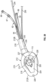
- Fig. 10 is a top plan view of an alternate embodiment of the SGA 110.
- the SGA 110 includes the neck 16, the supraglottic bowl 18, the cuff 20, the bowl surface 24, and the intubation conduit 14.
- the SGA 110 also includes the video imaging device 40, an alternate embodiment of the sealable slot 126 having an overlapping air-tight closure 128, and enlarged, generally oval shaped ventilation channels 124 in the bowl surface 24.
- Fig. 14 is a top plan view of an alternate embodiment of the SGA 112.
- the SGA 112 includes the neck 16, the supraglottic bowl 18, the cuff 20, the bowl surface 24, the intubation conduit 14, the sealable slot 30 and air-tight closure 32 and the gastric suction channel 28.
- the SGA 112 also includes an alternate embodiment of the ventilation channels 26, wherein the ventilation channels 26 are formed around the circumference of the opening of the intubation conduit 14 in the bowl surface 24. It will be understood that any number, and any arrangement in the bowl surface 24, of the ventilation channels 26 may be provided.
- the illustrated SGA 112 also includes a normally closed one-way valve 113 covering a channel 26 configured to receive an elongated video imaging device (not shown), and that allows forward or distal passage of the elongated video imaging device (not shown) that may be extended through the channel 26.
- the one-way valve 113 occluded or closed when the video imaging device (not shown) is not used, due to positive pressure on a distal (tracheal) surface of the one-way valve 113 during ventilation.
- Fig. 15 is a top plan view of an alternate embodiment of the SGA 114.
- the SGA 114 is substantially the same at the SGA 112 illustrated in Fig. 14 , and also includes a plurality of the ventilation channels formed around the circumference of the opening of the intubation conduit 14 in the bowl surface 24.
- the ventilation channels include the circular ventilation channels 26 and substantially oval shaped ventilation channels 130 that extend through the wall of the neck 16 and to the proximal end thereof. It will be understood that any number, combination, and arrangement in the bowl surface 24, of the ventilation channels 26 and 130 may be provided.
- Fig. 16 is a top plan view of an alternate embodiment of the SGA 116.
- the SGA 116 is similar to the SGA 110 illustrated in Fig. 10 , and includes the neck 16, the supraglottic bowl 18, the cuff 20, the bowl surface 24, the intubation conduit 14, and the sealable slot 126 having the overlapping air-tight closure 128 configuration.
- the SGA 116 also includes generally crescent shaped ventilation channels 132 in the bowl surface 24 that extend through the wall of the neck 16 and to the proximal end thereof.
- the SGA 116 further includes a distal sealing aperture 117 having a flexible, expandable collar 119.
- the aperture 117 of the flexible, expandable collar 119 has a diameter slightly smaller than an outside diameter of the ETT 92 or the introducing stylet 90 that will be inserted therethrough and defines an expandable aperture within the bowl surface 24.
- the ETT 92 or the introducing stylet 90 causes the expandable collar 119 to stretch open as an inside wall of the aperture 117 of the expandable collar 119 engages and maintains an airtight seal around the ETT 92 or the introducing stylet 90 to prevent gas leakage during ventilation via fluid flow channels, such as the ventilation channels 132.
- any sealable slot, such as the slot 126, formed in the SGA 116 may also be formed in the expandable collar 119.
- Fig. 17 is a top plan view of an alternate embodiment of the SGA 118.
- the SGA 118 includes the neck 16, the supraglottic bowl 18, the cuff 20, the bowl surface 24, and the sealable slot 30 and air-tight closure 32.
- the SGA 118 also includes alternate embodiments of the intubation conduit and the ventilation channel. As shown in Fig. 17 , the intubation conduit 133 and a ventilation channel 134 are parallel or collaterally arranged, separated by a wall 135, and extend longitudinally through the SGA 118 from a proximal end of the neck 16 to an opening in the bowl surface.
- Fig. 18 is a top plan view of an alternate embodiment of the SGA 120.
- the SGA 120 is similar to the SGA 118 illustrated in Fig. 17 , but additionally includes a first embodiment of a normally closed one-way door or valve 138 covering the opening of the intubation conduit 133, and shown in a closed position.
- Fig. 19 is a top plan view of an alternate embodiment of the SGA 122.
- the SGA 122 includes the neck 16, the supraglottic bowl 18, the cuff 20, the bowl surface 24, and the intubation conduit 14.
- the SGA 124 also includes the video imaging device 40, the alternate slot 30' and closure 32', and enlarged, generally oval shaped ventilation channels 136 in the bowl surface 24.
- the SGA 122 additionally includes a second embodiment of the normally closed one-way door or valve 140 covering the intubation conduit 14, and shown in a fully open position for clarity.
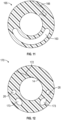
- the various embodiments of the SGA disclosed herein may include an occluding, interlocking closure 162 as shown in the alternate embodiment of the neck 160 in Fig. 7 .
- the neck 160 is a component of an SGA that is otherwise the same as the SGA 102.
- this embodiment of the SGA 102 also has an elongated, arcuate ventilation channel 163.
- the ventilation channel 163 is otherwise the same as the ventilation channels 26 described herein above. It will be understood that any of the embodiments of the SGAs described herein may have any one or more of the ventilation channels described herein, including the ventilation channel 163.
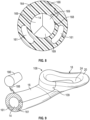
- FIG. 8 An overlapping, occluding, and interlocking closure 166 is shown in the alternate embodiment of the neck 164 in Fig 8 and the neck 165 in Fig. 11 .
- the neck 164 in Fig. 8 is a component of an SGA that is otherwise the same as the SGA 102.
- this embodiment of the SGA 102 also has an embodiment of a one-way valve 168 having three overlapping leaves 169, the purpose for which is described below, and two elongated ventilation channels 161.
- the one-way valve 168 is preferably positioned at the distal end of the intubation conduit 14, but may be positioned at any desired location within the intubation conduit 14.
- the neck 165 in Fig. 11 is a component of an SGA that is otherwise the same as the SGA 102.
- this embodiment of the SGA 102 also has the ventilation channel 163.
- Fig. 9 shows another embodiment of the SGA 108 having an overlapping, interlocking closure 109, and the two elongated ventilation channels 161. Also illustrated in Fig. 9 is a plug 186.
- the plug 186 may be attached to the neck 16 by a flexible connector 188.
- the plug 186 is configured to be inserted into the intubation conduit 14 at the proximal end 12B of the SGA 108 and to define a fluid-tight seal therein. Thus, the plug 186 may be inserted into and close the intubation conduit 14 when desired.
- Fig. 9 shows another embodiment of the SGA 108 having an overlapping, interlocking closure 109, and the two elongated ventilation channels 161.
- a plug 186 may be attached to the neck 16 by a flexible connector 188.
- the plug 186 is configured to be inserted into the intubation conduit 14 at the proximal end 12B of the SGA 108 and to define a fluid-tight seal therein.
- the plug 186 may
- the plug 186 may include a longitudinally extending elongated stem 190 to aid the user in positioning the plug 186 at any desired location in the intubation conduit 14, including the distal end thereof, the proximal end thereof, and any position intermediate the proximal and distal ends of the intubation conduit 14.
- FIG. 12 An overlapping, occluding closure 172 is shown in the alternate embodiment of the neck 170 in Fig 12 .
- the neck 170 in Fig. 12 is a component of an SGA that is otherwise the same as the SGA 102. As shown in Fig. 12 , this embodiment of the SGA 102 also has a plurality of the ventilation channels 26 and a plurality of oval shaped fluid flow channels 173. It will be understood that any of the embodiments of the SGAs described herein may have any one of the embodiments of the closures described herein.
- the cuff 20 of the supraglottic bowl 18 may have a split formed therein such that at the split, the two cuff surfaces may meet in a tangential fashion to improve the temporary occlusion of the split.
- Other interlocking or snap fit closure features may be provided to occlude the split.
- the slot 30, when open, allows the SGA 12 to be removed from around the ETT 92 after the ETT 92 is placed in the trachea but allows the cuff 20 of the supraglottic bowl 18 to maintain a tight cuff seal for ventilation.
- the supraglottic bowl 18 is configured to seal the periglottic area to ensure that all air, gas, or oxygen flows into the trachea and not into the esophagus or leak back into the atmosphere.
- the intubation conduit 14 may be formed with a normally closed one-way valve that allows forward or distal passage of the ETT 92 through the intubation conduit 14 and the one-way valve toward the trachea, but is occluded or closed when ventilating through the fluid flow channels 26 due to positive pressure on a distal (tracheal) surface of the one-way valve during ventilation.
- a normally closed one-way valve is the one-way valve 168 shown in Fig. 8 that is similar to an aortic valve.
- Another example of the one-way valve is the normally closed one-way valve 140, as shown in Fig. 19 .
- An additional example of the one-way valve is the normally closed one-way valve 138 shown in Fig. 18 . It will be understood that the one-way valves 138, 140, and 168 may be formed at the proximal end of the intubation conduit 14, the distal end of the intubation conduit 14, or at any other desired location within the intubation conduit 14.
- the intubation conduit 14 may be formed having one or more reduced diameter portions (not shown) along the length of the intubation conduit 14.
- This reduced diameter portion or portions has a diameter slightly smaller than an outside diameter of the ETT 92 or the introducing stylet 90 that will be inserted therethrough and defines an expandable aperture within the intubation conduit 14.
- the ETT 92 or the introducing stylet 90 causes the expandable aperture to stretch open as an inside wall of the expandable aperture engages and maintains an airtight seal around the ETT 92 or the introducing stylet 90 to prevent gas leakage during ventilation via fluid flow channels, such as the fluid flow channels 26 configured as ventilation channels.
- fluid flow channels such as the fluid flow channels 26 configured as ventilation channels.
- any sealable slot 30 formed in the SGA 12 will also be formed in the reduced diameter portion.
- the proximal end 12B of the SGA 12 may have a cap 174 attached thereto, as shown in Fig. 13 .
- the illustrated cap 174 includes a body 176 having an aperture 178 formed therethrough and a closure 180 movably attached to the body 176, wherein the body 176 is configured to attach to, or be formed on, the proximal end 12B of the SGA 12.
- the aperture 178 may have a diameter slightly smaller than an outside diameter of the ETT 92 that will be inserted therethrough and is expandable.
- the closure 180 includes a protrusion or closure plug 182 that is configured to be inserted into and close the aperture 178 when it desired to have the proximal end 12B closed.
- the cap 174 may be removable, or may have a sealable slot 184 formed therein, wherein the sealable slot 184 is similar to and preferably aligned with the sealable slot 30.
- the SGA 12 may be formed with any combination of one or more of the expandable collar 119, the normally closed one-way valves 138, 140, and 168, the plug 186, the cap 174, and/or the reduced diameter portions that define expandable apertures that are configured to prevent retrograde air or fluid passage during ventilation through the ventilation channel or channels 26.
- these features i.e., the expandable collar 119, the normally closed one-way valves 138, 140, and 168, the plug 186, the cap 174, and the reduced diameter portions that define expandable apertures
- intubation conduit occluding features may be collectively referred to as intubation conduit occluding features.
- conduit 14 may, if desired, function as a working channel for instruments associated with a variety of medical procedures, including but not limited to bronchoscopy, laryngoscopy, vocal cord examination, vocal cord procedures, and the like.
- Fig. 20 is a perspective view of a second embodiment of the improved SGA assembly illustrated in Fig. 1 and shown generally at 210.
- the SGA assembly 210 includes the introducing stylet 90 (not shown in Fig. 20 ) with the ETT 92 mounted thereon extending through the SGA assembly 210.
- the SGA assembly 210 is configured to ventilate and have the ETT 92 carried therein such that a patient may be simultaneously ventilated and intubated.
- the SGA assembly 210 includes the SGA 212 having the distal end 12A, the proximal end 212B, and the longitudinally extending intubation conduit 214 formed therethrough.
- the SGA 212 includes the elongated neck 216 formed at the proximal end 212B thereof and the supraglottic bowl 218 formed at the distal end 212A thereof and extending from the neck 216.
- the supraglottic bowl 218 includes the cuff 220 and defines the bowl surface 224.
- a plurality of the fluid flow channels 226 may be formed longitudinally through the neck 216 to the bowl surface 224. In Fig. 20 four such fluid flow channels 226 are illustrated, however any desired number of fluid flow channels 226 may be formed in the SGA 212.
- One or more of the fluid flow channels 226 are configured as ventilation channels that advantageously allow for patient ventilation simultaneously with, and independent of patient intubation.
- one of the fluid flow channels may be configured as a video imaging channel 227, the opening of which may include the normally closed one-way valve 113 described above.
- the SGA 212 may include the gastric suction channel 228 formed longitudinally through the neck 216 to the distal end 212A of the cuff 220 of the bowl 218.
- the SGA assembly 210 also includes the sealable slot 230 having the elongated, air-tight closure 232.
- the sealable slot 230 is formed along the entire length of the intubation conduit 214, from the proximal end 212B of the neck 216 to the opening of the intubation conduit 214 in the bowl surface 224 and continuously through the bowl surface 224 and the cuff 220 of the supraglottic bowl 218.
- the tube assembly 62 extends outwardly from the proximal end 212B of the SGA 212 and includes a plurality of the first fluid flow tubes 64, the proximal ends of which merge into the single second fluid flow tube 66.
- the conventional 15 mm connector 68 is attached to the proximal end of the second fluid flow tube 66.
- a video line 234 may be connected to a video imaging device (not shown), extends outwardly from the video imaging channel 227 at the proximal end 212B of the SGA 212, and may be operationally connected, for example wired or wirelessly connected, to a monitor, such as the video monitor 98.
- a gastric suction tube 236 extends outwardly from the gastric suction channel 228 at the proximal end 212B of the SGA 212, and may be operationally connected to a source of suction (not shown).
Landscapes
- Health & Medical Sciences (AREA)
- Pulmonology (AREA)
- Emergency Medicine (AREA)
- Engineering & Computer Science (AREA)
- Anesthesiology (AREA)
- Biomedical Technology (AREA)
- Heart & Thoracic Surgery (AREA)
- Hematology (AREA)
- Life Sciences & Earth Sciences (AREA)
- Animal Behavior & Ethology (AREA)
- General Health & Medical Sciences (AREA)
- Public Health (AREA)
- Veterinary Medicine (AREA)
- Otolaryngology (AREA)
- External Artificial Organs (AREA)
- Endoscopes (AREA)
Claims (24)
- Bifunktionaler, intubierender und beatmender supraglottischer Luftweg, umfassend:eine supraglottische Schale (18, 218), die ein distales Ende (12a, 212a) definiert, einen Hals (16, 142, 146, 160, 164, 165, 170, 216), der sich von der supraglottischen Schale (18, 218) nach außen erstreckt und ein proximales Ende (12b, 212b) definiert, eine durch diese hindurch gebildete, sich in Längsrichtung erstreckende Intubationsleitung (14, 133, 24), wobei die supraglottische Schale (18, 218) eine Manschette (20, 220) beinhaltet und eine Schalenoberfläche (24, 224) definiert, wobei sich die Intubationsleitung (14, 133, 214) von dem proximalen Ende (12b, 212b) des Halses (16, 142, 146, 160, 164, 165, 170, 216) zu einer Öffnung in der Schalenoberfläche erstreckt (24, 224) und wobei die Intubationsleitung derart (14, 133, 214) konfiguriert ist, dass ein Endotrachealtubus (ET (92)T) durch diese hindurch eingeführt werden kann; undeine Vielzahl von Fluidströmungskanälen (26, 226), die in Längsrichtung durch eine Wand (135) des Halses (16, 142, 146, 160, 164, 165, 170, 216) des supraglottischen Luftwegs, kollateral zu der Intubationsleitung (14, 133, 214) und von dem proximalen Ende (12b, 212b) zu der Schalenoberfläche (24, 224) innerhalb der supraglottischen Schale (18, 218) gebildet ist;wobei mindestens einer der Vielzahl von Fluidströmungskanälen (26, 226) als ein Beatmungskanal (134, 163) für den Luftstrom von dem proximalen Ende (12b, 212b) zu der supraglottischen Schale (18, 218) konfiguriert ist;wobei der supraglottische Luftweg ferner einen Fluidströmungstubus, der innerhalb des Beatmungskanals (134, 163) angeschlossen ist, und einen 15-mm-Anschluss (70) an einem proximalen Ende (12b, 212b) des Fluidströmungstubus beinhaltet; dadurch gekennzeichnet, dass der bifunktionale, intubierende und beatmende supraglottische Luftweg ferner Folgendes umfasst:
einen abdichtbaren Schlitz (126, 148, 184, 230), der sich über eine gesamte Länge der Intubationsleitung (14, 133, 214) erstreckt, wobei sich der abdichtbare Schlitz (126, 148, 184, 230) durch den Hals (16, 142, 146, 160, 164, 165, 170, 216), die Manschette (20, 220) und die Schalenoberfläche erstreckt. - Bifunktionaler, intubierender und beatmender supraglottischer Luftweg nach Anspruch 1, ferner beinhaltend ein eine Intubationsleitung (14, 133, 214) okkludierendes Merkmal.
- Bifunktionaler, intubierender und beatmender supraglottischer Luftweg nach Anspruch 2, ferner beinhaltend einen Stopfen (186), der an dem proximalen Ende (12b, 212b) des Halses (16, 142, 146, 160, 164, 165, 170, 216) angebracht ist, wobei der Stopfen (186) dazu konfiguriert ist, in die Intubationsleitung (14, 133, 214) an dem proximalen Ende (12b, 212b) des Halses (16, 142, 146, 160, 164, 165, 170, 216) eingeführt zu werden und darin eine fluiddichte Abdichtung zu definieren.
- Bifunktionaler, intubierender und beatmender supraglottischer Luftweg nach Anspruch 3, wobei der Stopfen (186) einen sich in Längsrichtung erstreckenden länglichen Schaft (190) beinhaltet, der dazu konfiguriert ist, zu ermöglichen, dass der Stopfen (186) in eine beliebige Stelle innerhalb der Intubationsleitung (14, 133, 214) hineingedrückt und positioniert werden kann.
- Bifunktionaler intubierender und beatmender supraglottischer Luftweg nach Anspruch 2, ferner beinhaltend ein normalerweise geschlossenes Einwegeventil (113, 138, 140) innerhalb der Intubationsleitung (14, 133, 214), wobei das Einwegeventil (168) dazu konfiguriert ist, einen distalen Durchgang von einem des ETT (92) und eines Einführungsstiletts (90, 150), auf dem der ETT (92) montiert sein kann, durch die Intubationsleitung (14, 133, 214) zu ermöglichen, und ferner dazu konfiguriert ist, die Intubationsleitung (14, 133, 214) während der Beatmung durch den Fluidströmungskanal zu okkludieren, wobei das normalerweise geschlossene Einwegeventil (113, 138, 140) an einem eines distalen Endes (12a, 212a) der Intubationsleitung (14, 133, 214), eines proximalen Endes (12b, 212b) der Intubationsleitung (14, 13) und einer Stelle zwischen dem distalen Ende (12a, 212a) und dem proximalen Ende (12b, 212b) der Intubationsleitung (14, 133, 214) ausgebildet ist.
- Bifunktionaler, intubierender und beatmender supraglottischer Luftweg nach Anspruch 2, ferner beinhaltend eine Kappe (174), die an dem proximalen Ende (12b, 212b) des Halses (16, 142, 146, 160, 164, 165, 170, 216) angebracht ist, wobei die Kappe (174) einen Körper (176) mit einer durch diesen hindurch ausgebildeten Öffnung (117, 178) und einen beweglich an dem Körper (176) angebrachten Verschluss (32', 166, 180) beinhaltet und dazu konfiguriert ist, die Öffnung (117, 178) des Körpers (176) zu verschließen.
- Bifunktionaler, intubierender und beatmender supraglottischer Luftweg nach Anspruch 6, wobei die Öffnung (117, 178) einen Durchmesser aufweist, der geringfügig kleiner als ein Außendurchmesser von einem von dem ETT (92) und einem Einführungsstilett (90, 150), auf dem der ETT (92) montiert sein kann, der durch sie eingeführt wird, ist und expandierbar ist und wobei die expandierbare Öffnung (117, 178) dazu konfiguriert ist, mit dem einen des ETT (92) und eines durch diesen hindurch eingeführten Einführungsstiletts (90, 150) in Eingriff zu gelangen und eine luftdichte Abdichtung gegenüber diesem aufrechtzuerhalten, um Gasleckagen während der Beatmung über den Fluidströmungskanal zu verhindern.
- Bifunktionaler, intubierender und beatmender supraglottischer Luftweg nach Anspruch 7, wobei die Kappe (174) einen darin ausgebildeten, abdichtbaren Schlitz (126, 148, 184, 230) beinhaltet, der an dem abdichtbaren Schlitz (126, 148, 184, 230) des supraglottischen Luftwegs ausgerichtet ist.
- Bifunktionaler, intubierender und beatmender supraglottischer Luftweg nach Anspruch 2, ferner beinhaltend einen Abschnitt (67) mit verringertem Durchmesser innerhalb der Intubationsleitung (14, 133, 214), wobei der Abschnitt (67) mit verringertem Durchmesser einen Durchmesser aufweist, der geringfügig kleiner als ein Außendurchmesser von einem des ETT (92), der durch ihn eingeführt wird, und eines Einführungsstiletts (90, 150), auf dem der ETT (92) montiert sein kann, ist und eine expandierbare Öffnung (117, 178) innerhalb der Intubationsleitung (14, 133, 214) definiert und wobei die expandierbare Öffnung (117, 178) dazu konfiguriert ist, sich zum Öffnen auszudehnen, wenn eine Innenwand (135) der expandierbaren Öffnung (117, 178) mit dem einen des ETT (92) und des Einführungsstiletts (90, 150) in Eingriff gelangt und eine luftdichte Abdichtung gegenüber diesem während der Beatmung mit Luft über die Fluidströmungskanäle aufrechterhält.
- Bifunktionaler, intubierender und beatmender supraglottischer Luftweg nach Anspruch 2, ferner beinhaltend eine Dichtungsöffnung (117, 178), die einen flexiblen, expandierbaren Kragen (119) innerhalb der Intubationsleitung (14, 133, 214) aufweist, wobei der flexible, expandierbare Kragen (119) dazu konfiguriert ist, einen distalen Durchgang von einem des ETT (92) und eines Einführungsstiletts (90, 150), auf dem der ETT (92) montiert sein kann, durch die Intubationsleitung (14, 133, 214) zu ermöglichen, und ferner dazu konfiguriert ist, die Intubationsleitung (14, 133, 214) während der Beatmung durch den Beatmungskanal (134, 163) zu okkludieren, wobei der flexible, expandierbare Kragen (119) an einem eines distalen Endes (12a, 212a) der Intubationsleitung (14, 133, 214), eines proximalen Endes (12b, 212b) der Intubationsleitung (14, 133, 214) und einer Stelle zwischen dem distalen Ende (12a, 212a) und dem proximalen Ende (12b, 212b) der Intubationsleitung (14, 133, 214) ausgebildet ist.
- Bifunktionaler, intubierender und beatmender supraglottischer Luftweg nach Anspruch 1, wobei der abdichtbare Schlitz (126, 148, 184, 230) einen ersten Abschnitt (67) entlang einer Länge der Intubationsleitung (14, 133, 214) in dem Hals (16, 142, 146, 160, 164, 165, 170, 216) und einen zweiten Abschnitt (67) entlang einer Länge der Intubationsleitung (14, 133, 214) in der Schalenoberfläche (24, 224) beinhaltet, wobei der abdichtbare Schlitz (126, 148, 184, 230) nicht in der Manschette (20, 220) ausgebildet ist.
- Bifunktionaler, intubierender und beatmender supraglottischer Luftweg nach Anspruch 11, wobei die Manschette (20, 220) aus expandierbarem, dehnbarem Material ausgebildet ist.
- Bifunktionaler, intubierender und beatmender supraglottischer Luftweg nach Anspruch 1, ferner beinhaltend einen Magensaugkanal (28, 228), der in Längsrichtung durch die Wand (135) des supraglottischen Luftwegs von dem proximalen Ende (12b, 212b) des Halses (16, 142, 146, 160, 164, 165, 170, 216) zu einem distalen Ende (12a, 212a) der Manschette (20, 220) der Schale ausgebildet ist.
- Bifunktionaler, intubierender und beatmender supraglottischer Luftweg, umfassend:eine supraglottische Schale (18, 218), die ein distales Ende (12a, 212a) definiert, einen Hals (16, 142, 146, 160, 164, 165, 170, 216), der sich von der supraglottischen Schale (18, 218) nach außen erstreckt und ein proximales Ende (12b, 212b) definiert, eine durch diese hindurch gebildete, sich in Längsrichtung erstreckende Intubationsleitung (14, 133, 24), wobei die supraglottische Schale (18, 218) eine Manschette (20, 220) beinhaltet und eine Schalenoberfläche (24, 224) definiert, wobei sich die Intubationsleitung (14, 133, 214) von dem proximalen Ende (12b, 212b) des Halses (16, 142, 146, 160, 164, 165, 170, 216) zu einer Öffnung in der Schalenoberfläche erstreckt (24, 224) und wobei die Intubationsleitung (14, 133, 214) derart konfiguriert ist, dass ein Endotrachealtubus (ETT) durch diese hindurch eingeführt werden kann;eine Vielzahl von Fluidströmungskanälen (26, 226), die in Längsrichtung durch eine Wand (135) des Halses (16, 142, 146, 160, 164, 165, 170, 216) des supraglottischen Luftwegs, kollateral zu der Intubationsleitung (14, 133, 214) und von dem proximalen Ende (12b, 212b) zu der Schalenoberfläche (24, 224) innerhalb der supraglottischen Schale (18, 218) ausgebildet ist; wobei mindestens einer der Vielzahl von Fluidströmungskanälen (26, 226) als ein Beatmungskanal (134, 163) für den Luftstrom von dem proximalen Ende (12b, 212b) zu der supraglottischen Schale (18, 218) ausgebildet ist;wobei der supraglottische Luftweg ferner einen Fluidströmungstubus,der innerhalb des Beatmungskanals (134, 163) angeschlossen ist, und einen 15-mm-Anschluss (70) an einem proximalen Ende (12b, 212b) des Fluidströmungstubus beinhaltet; undein spaltfähiges Merkmal, das sich entlang einer gesamten Länge der Intubationsleitung (14, 133, 214) erstreckt, wobei das spaltfähige Merkmal sich durch den Hals (16, 142, 146, 160, 164, 165, 170, 216), die Manschette (20, 220) und die Schalenoberfläche (24, 224) erstreckt, wobei das spaltfähige Merkmal einen oder mehrere Schnitte entlang einer Linie beinhaltet, die eine Stelle für einen Schlitz (30) definiert, wobei die Schnitte nur einen Abschnitt (67) einer Dicke einer Wand (135) des supraglottischen Luftwegs durchdringen, sodass das spaltfähige Merkmal luftdicht und ungeöffnet ist, bis es von einem Benutzer aufgedrückt wird, um den Schlitz (30) zu definieren.
- Bifunktionaler, intubierender und beatmender supraglottischer Luftweg nach Anspruch 1, wobei der abdichtbare Schlitz (126, 148, 184, 230) einen luftdichten Verschluss (32, 232) entlang seiner Länge beinhaltet.
- Bifunktionaler, intubierender und beatmender supraglottischer Luftweg nach Anspruch 15, wobei der luftdichte Verschluss (32, 232) eines von überlappend, überlappend und okkludierend, überlappend und ineinandergreifend oder überlappend, okkludierend und ineinandergreifend ist.
- Bifunktionaler, intubierender und beatmender supraglottischer Luftweg nach Anspruch 1, ferner beinhaltend einen Videoabbildungskanal (27, 227), der in Längsrichtung durch die Wand (135) des supraglottischen Luftwegs von dem proximalen Ende (12b, 212b) des Halses (16, 142, 146, 160, 164, 165, 170, 216) zu der Schalenoberfläche (24, 224) ausgebildet ist, wobei der Videoabbildungskanal (27, 227) eine darin montierte Videoabbildungsvorrichtung (40) aufweist.
- Bifunktionaler, intubierender und beatmender supraglottischer Luftweg nach Anspruch 17, wobei ein Abschnitt (67) des Videoabbildungskanals (27, 227) sich von der Schalenoberfläche (24, 224) nach außen in die supraglottische Schale (18, 218) erstreckt.
- Bifunktionaler, intubierender und beatmender supraglottischer Luftweg nach Anspruch 18, wobei der Abschnitt (67) des Videoabbildungskanals (27, 227), der sich von der Schalenoberfläche (24, 224) nach außen in die supraglottische Schale (18, 218) erstreckt, so konfiguriert ist, dass er eines von gelenkig und aus formbarem Material ausgebildet ist.
- Bifunktionaler, intubierender und beatmender supraglottischer Luftweg nach Anspruch 1, wobei der supraglottische Luftweg eine Rampe (36) beinhaltet, die in der Schalenoberfläche (24, 224) ausgebildet ist, wobei die Rampe (36) dazu konfiguriert ist, die Fortbewegung des ETT (92) anterior abzulenken.
- Bifunktionaler, intubierender und beatmender supraglottischer Luftweg nach Anspruch 20, wobei die Rampe (36) eines von aufblasbar, gelenkig oder erhaben ist.
- Bifunktionaler, intubierender und beatmender supraglottischer Luftweg nach Anspruch 1, wobei der Anschluss (70) als einer eines starren, festen, teleskopierbaren, faltbaren und klappbaren Anschlusses (70) konfiguriert ist, der ferner dazu konfiguriert ist, es dem Benutzer zu ermöglichen, einen relativen Abstand zwischen dem zweiten Fluidströmungstubus (66) und dem ETT (92) zu ändern.
- Bifunktionaler, intubierender und beatmender supraglottischer Luftweg nach Anspruch 1, wobei der Fluidströmungstubus einer aus einer Vielzahl von ersten Fluidströmungstuben (64) ist, deren proximale Enden in einen einzigen zweiten Fluidströmungstubus (66) münden, wobei die ersten Fluidströmungstuben (64) und der zweite Fluidströmungstubus (66) eine Tubusanordnung (62) definieren, wobei ein distales Ende (12a, 212a) jedes der ersten Fluidströmungstuben (64) innerhalb eines der Vielzahl von ersten Fluidströmungskanälen (26, 226) angeschlossen ist und wobei der 15-mm-Anschluss (70) an einem proximalen Ende (12b, 212b) des zweiten Fluidströmungstubus (66) angebracht ist.
- Bifunktionaler, intubierender und beatmender supraglottischer Luftweg nach Anspruch 1, wobei einer der Vielzahl von Fluidströmungskanälen (26, 226) als ein glottischer Saugkanal (29) konfiguriert ist.
Applications Claiming Priority (4)
| Application Number | Priority Date | Filing Date | Title |
|---|---|---|---|
| US201862769725P | 2018-11-20 | 2018-11-20 | |
| US201962916386P | 2019-10-17 | 2019-10-17 | |
| US201962916398P | 2019-10-17 | 2019-10-17 | |
| PCT/US2019/062109 WO2020106666A1 (en) | 2018-11-20 | 2019-11-19 | Bi-functional intubating and ventilating supraglottic airway |
Publications (3)
| Publication Number | Publication Date |
|---|---|
| EP3883449A1 EP3883449A1 (de) | 2021-09-29 |
| EP3883449A4 EP3883449A4 (de) | 2022-09-28 |
| EP3883449B1 true EP3883449B1 (de) | 2024-02-14 |
Family
ID=70728691
Family Applications (1)
| Application Number | Title | Priority Date | Filing Date |
|---|---|---|---|
| EP19886982.8A Active EP3883449B1 (de) | 2018-11-20 | 2019-11-19 | Bifunktionaler intubierender und beatmender supraglottischer luftweg |
Country Status (8)
| Country | Link |
|---|---|
| US (1) | US10702665B2 (de) |
| EP (1) | EP3883449B1 (de) |
| JP (1) | JP2022508137A (de) |
| CN (1) | CN112839563A (de) |
| AU (1) | AU2019384517A1 (de) |
| CA (1) | CA3112459A1 (de) |
| MX (1) | MX2021003612A (de) |
| WO (1) | WO2020106666A1 (de) |
Families Citing this family (6)
| Publication number | Priority date | Publication date | Assignee | Title |
|---|---|---|---|---|
| US10596339B2 (en) | 2018-05-21 | 2020-03-24 | Sridhar R. Musuku | Intubation devices and methods of use |
| WO2020118374A1 (en) * | 2018-12-13 | 2020-06-18 | Baska, Meenakshi | A device for maintaining an airway in a patient |
| WO2021029849A1 (en) * | 2019-08-09 | 2021-02-18 | Ony Biotech Inc. | Medicament delivery device |
| AR118974A1 (es) * | 2020-05-21 | 2021-11-17 | Raxte S A | Dispositivo de intubado laringeotraqueal y procedimientos de intubación |
| US12453829B2 (en) | 2020-12-02 | 2025-10-28 | Chong S. Kim | Multipurpose airway device |
| CN115738005A (zh) * | 2022-11-15 | 2023-03-07 | 杨明 | 一种气道管理系统 |
Family Cites Families (20)
| Publication number | Priority date | Publication date | Assignee | Title |
|---|---|---|---|---|
| US4641646A (en) * | 1985-04-05 | 1987-02-10 | Kenneth E. Schultz | Endotracheal tube/respirator tubing connecting lock mechanism and method of using same |
| US5477851A (en) * | 1995-01-26 | 1995-12-26 | Callaghan; Eric B. | Laryngeal mask assembly and method for removing same |
| US20050139220A1 (en) * | 1996-02-26 | 2005-06-30 | Evergreen Medical Incorporated | Method and apparatus for ventilation / oxygenation during guided insertion of an endotracheal tube |
| US5623921A (en) | 1996-04-10 | 1997-04-29 | Kinsinger; J. William | Laryngeal mask airway and method for its use |
| US6070581A (en) | 1996-10-16 | 2000-06-06 | Augustine Medical, Inc. | Laryngeal airway device |
| US6626169B2 (en) * | 2001-05-17 | 2003-09-30 | Elisha Medical Technologies Ltd. | Anatomical airway ventilation intubating and resuscitation device |
| GB0218868D0 (en) | 2002-08-14 | 2002-09-25 | Nasir Muhammed A | Improved airway management device |
| DE202010018619U1 (de) * | 2009-07-06 | 2018-11-07 | Teleflex Life Sciences Unlimited Company | Künstlicher Atemweg |
| GB2472063B (en) | 2009-07-23 | 2011-06-15 | Vikas Sharma | Split intubating laryngeal mask airway |
| US9357905B2 (en) | 2012-06-01 | 2016-06-07 | Robert Molnar | Airway device, airway assist device and the method of using same |
| US20140276178A1 (en) | 2013-03-13 | 2014-09-18 | David Lew Simon | Multi-lumen breathing tube device |
| GB2546167B (en) * | 2013-12-17 | 2018-02-28 | Aslam Nasir Muhammed | Intubating Airway Device |
| US9463296B2 (en) | 2014-04-01 | 2016-10-11 | Michael S. Stix | Laryngeal mask with piriform-fossa conduit |
| US10786640B2 (en) * | 2015-05-15 | 2020-09-29 | Parker-Hannifin Corporation | Reversible airway device and related method for ventilating a subject |
| CN108697317B (zh) | 2016-01-07 | 2021-10-08 | 格伦·P·加德纳 | 气管内导管插入装置 |
| US10478054B2 (en) | 2016-02-12 | 2019-11-19 | Ambu A/S | Endotracheal tube with visualization capabilities and a laryngeal mask |
| FR3056406B1 (fr) | 2016-09-27 | 2018-11-30 | Deltamedics | Dispositif larynge comprenant un tube avec une fente laterale |
| US20180169365A1 (en) * | 2016-12-21 | 2018-06-21 | University Of Washington | Intubating Neonatal Laryngeal Mask Airway |
| CN209137662U (zh) | 2018-03-30 | 2019-07-23 | 无锡圣诺亚科技有限公司 | 便于脱卸的插管喉罩 |
| US11426548B2 (en) * | 2018-05-11 | 2022-08-30 | Gary Zhou | Combined laryngeal-bronchial lung separation system |
-
2019
- 2019-11-19 EP EP19886982.8A patent/EP3883449B1/de active Active
- 2019-11-19 CA CA3112459A patent/CA3112459A1/en active Pending
- 2019-11-19 MX MX2021003612A patent/MX2021003612A/es unknown
- 2019-11-19 CN CN201980067951.1A patent/CN112839563A/zh active Pending
- 2019-11-19 WO PCT/US2019/062109 patent/WO2020106666A1/en not_active Ceased
- 2019-11-19 US US16/687,877 patent/US10702665B2/en active Active
- 2019-11-19 AU AU2019384517A patent/AU2019384517A1/en not_active Abandoned
- 2019-11-19 JP JP2021527841A patent/JP2022508137A/ja not_active Withdrawn
Also Published As
| Publication number | Publication date |
|---|---|
| US20200155781A1 (en) | 2020-05-21 |
| CN112839563A (zh) | 2021-05-25 |
| CA3112459A1 (en) | 2020-05-28 |
| JP2022508137A (ja) | 2022-01-19 |
| EP3883449A1 (de) | 2021-09-29 |
| EP3883449A4 (de) | 2022-09-28 |
| US10702665B2 (en) | 2020-07-07 |
| WO2020106666A1 (en) | 2020-05-28 |
| MX2021003612A (es) | 2021-05-28 |
| AU2019384517A1 (en) | 2021-03-18 |
Similar Documents
| Publication | Publication Date | Title |
|---|---|---|
| EP3883449B1 (de) | Bifunktionaler intubierender und beatmender supraglottischer luftweg | |
| US20230210628A1 (en) | Medical devices for airway management and methods of placement | |
| CN210992370U (zh) | 气道装置、及基于气道装置的喉-支联合肺分离系统 | |
| US7921847B2 (en) | Device and method for placing within a patient an enteral tube after endotracheal intubation | |
| US6443156B1 (en) | Separable double lumen endotracheal tube | |
| US5623921A (en) | Laryngeal mask airway and method for its use | |
| CA2101939C (en) | Artificial airway device | |
| EP2903673B1 (de) | Umkehrbare atemwegsvorrichtung | |
| CA1324551C (en) | Artificial airway device | |
| AU675027B2 (en) | Esophageal-tracheal double lumen airway | |
| US7174889B2 (en) | Device for insertion of endotracheal tube | |
| US5964217A (en) | Method and apparatus for ventilation/oxygenation during guided insertion of an endotracheal tube | |
| US10786640B2 (en) | Reversible airway device and related method for ventilating a subject | |
| WO2002092144A3 (en) | Anatomical airway ventilation intubating and resuscitating device | |
| JPH02283378A (ja) | 人工呼吸装置 | |
| US10675425B2 (en) | Reversible airway device and related method for ventilating a subject | |
| US20190083727A1 (en) | Removable Fiberoptic Adapter for Difficult Intubation with Laryngeal Mask Airway | |
| WO2015078204A1 (zh) | 一种安全三通道喉罩 | |
| IE922073A1 (en) | ARTIFICIAL AIRWAY DEVICE IE | |
| US20220062572A1 (en) | A device for maintaining an airway in a patient | |
| US20210113798A1 (en) | Connector | |
| JPH06217933A (ja) | 内視鏡 | |
| US20060254594A1 (en) | Laryngeal mask airway | |
| CN220276084U (zh) | 一种双腔支气管导管 | |
| US20160045699A1 (en) | Fiberoptic Bronchoscopy Intubation Device and Method of Using the Same |
Legal Events
| Date | Code | Title | Description |
|---|---|---|---|
| STAA | Information on the status of an ep patent application or granted ep patent |
Free format text: STATUS: THE INTERNATIONAL PUBLICATION HAS BEEN MADE |
|
| PUAI | Public reference made under article 153(3) epc to a published international application that has entered the european phase |
Free format text: ORIGINAL CODE: 0009012 |
|
| STAA | Information on the status of an ep patent application or granted ep patent |
Free format text: STATUS: REQUEST FOR EXAMINATION WAS MADE |
|
| 17P | Request for examination filed |
Effective date: 20210402 |
|
| AK | Designated contracting states |
Kind code of ref document: A1 Designated state(s): AL AT BE BG CH CY CZ DE DK EE ES FI FR GB GR HR HU IE IS IT LI LT LU LV MC MK MT NL NO PL PT RO RS SE SI SK SM TR |
|
| DAV | Request for validation of the european patent (deleted) | ||
| DAX | Request for extension of the european patent (deleted) | ||
| A4 | Supplementary search report drawn up and despatched |
Effective date: 20220829 |
|
| RIC1 | Information provided on ipc code assigned before grant |
Ipc: A61M 16/04 20060101ALI20220823BHEP Ipc: A61B 1/00 20060101AFI20220823BHEP |
|
| P01 | Opt-out of the competence of the unified patent court (upc) registered |
Effective date: 20230512 |
|
| GRAP | Despatch of communication of intention to grant a patent |
Free format text: ORIGINAL CODE: EPIDOSNIGR1 |
|
| STAA | Information on the status of an ep patent application or granted ep patent |
Free format text: STATUS: GRANT OF PATENT IS INTENDED |
|
| INTG | Intention to grant announced |
Effective date: 20230919 |
|
| GRAS | Grant fee paid |
Free format text: ORIGINAL CODE: EPIDOSNIGR3 |
|
| GRAA | (expected) grant |
Free format text: ORIGINAL CODE: 0009210 |
|
| STAA | Information on the status of an ep patent application or granted ep patent |
Free format text: STATUS: THE PATENT HAS BEEN GRANTED |
|
| AK | Designated contracting states |
Kind code of ref document: B1 Designated state(s): AL AT BE BG CH CY CZ DE DK EE ES FI FR GB GR HR HU IE IS IT LI LT LU LV MC MK MT NL NO PL PT RO RS SE SI SK SM TR |
|
| REG | Reference to a national code |
Ref country code: GB Ref legal event code: FG4D |
|
| REG | Reference to a national code |
Ref country code: CH Ref legal event code: EP |
|
| REG | Reference to a national code |
Ref country code: DE Ref legal event code: R096 Ref document number: 602019046708 Country of ref document: DE |
|
| REG | Reference to a national code |
Ref country code: IE Ref legal event code: FG4D |
|
| REG | Reference to a national code |
Ref country code: LT Ref legal event code: MG9D |
|
| REG | Reference to a national code |
Ref country code: NL Ref legal event code: MP Effective date: 20240214 |
|
| PG25 | Lapsed in a contracting state [announced via postgrant information from national office to epo] |
Ref country code: IS Free format text: LAPSE BECAUSE OF FAILURE TO SUBMIT A TRANSLATION OF THE DESCRIPTION OR TO PAY THE FEE WITHIN THE PRESCRIBED TIME-LIMIT Effective date: 20240614 |
|
| PG25 | Lapsed in a contracting state [announced via postgrant information from national office to epo] |
Ref country code: LT Free format text: LAPSE BECAUSE OF FAILURE TO SUBMIT A TRANSLATION OF THE DESCRIPTION OR TO PAY THE FEE WITHIN THE PRESCRIBED TIME-LIMIT Effective date: 20240214 |
|
| PG25 | Lapsed in a contracting state [announced via postgrant information from national office to epo] |
Ref country code: GR Free format text: LAPSE BECAUSE OF FAILURE TO SUBMIT A TRANSLATION OF THE DESCRIPTION OR TO PAY THE FEE WITHIN THE PRESCRIBED TIME-LIMIT Effective date: 20240515 |
|
| REG | Reference to a national code |
Ref country code: AT Ref legal event code: MK05 Ref document number: 1656298 Country of ref document: AT Kind code of ref document: T Effective date: 20240214 |
|
| PG25 | Lapsed in a contracting state [announced via postgrant information from national office to epo] |
Ref country code: NL Free format text: LAPSE BECAUSE OF FAILURE TO SUBMIT A TRANSLATION OF THE DESCRIPTION OR TO PAY THE FEE WITHIN THE PRESCRIBED TIME-LIMIT Effective date: 20240214 Ref country code: HR Free format text: LAPSE BECAUSE OF FAILURE TO SUBMIT A TRANSLATION OF THE DESCRIPTION OR TO PAY THE FEE WITHIN THE PRESCRIBED TIME-LIMIT Effective date: 20240214 Ref country code: RS Free format text: LAPSE BECAUSE OF FAILURE TO SUBMIT A TRANSLATION OF THE DESCRIPTION OR TO PAY THE FEE WITHIN THE PRESCRIBED TIME-LIMIT Effective date: 20240514 |
|
| PG25 | Lapsed in a contracting state [announced via postgrant information from national office to epo] |
Ref country code: ES Free format text: LAPSE BECAUSE OF FAILURE TO SUBMIT A TRANSLATION OF THE DESCRIPTION OR TO PAY THE FEE WITHIN THE PRESCRIBED TIME-LIMIT Effective date: 20240214 |
|
| PG25 | Lapsed in a contracting state [announced via postgrant information from national office to epo] |
Ref country code: AT Free format text: LAPSE BECAUSE OF FAILURE TO SUBMIT A TRANSLATION OF THE DESCRIPTION OR TO PAY THE FEE WITHIN THE PRESCRIBED TIME-LIMIT Effective date: 20240214 |
|
| PG25 | Lapsed in a contracting state [announced via postgrant information from national office to epo] |
Ref country code: RS Free format text: LAPSE BECAUSE OF FAILURE TO SUBMIT A TRANSLATION OF THE DESCRIPTION OR TO PAY THE FEE WITHIN THE PRESCRIBED TIME-LIMIT Effective date: 20240514 Ref country code: NO Free format text: LAPSE BECAUSE OF FAILURE TO SUBMIT A TRANSLATION OF THE DESCRIPTION OR TO PAY THE FEE WITHIN THE PRESCRIBED TIME-LIMIT Effective date: 20240514 Ref country code: NL Free format text: LAPSE BECAUSE OF FAILURE TO SUBMIT A TRANSLATION OF THE DESCRIPTION OR TO PAY THE FEE WITHIN THE PRESCRIBED TIME-LIMIT Effective date: 20240214 Ref country code: LT Free format text: LAPSE BECAUSE OF FAILURE TO SUBMIT A TRANSLATION OF THE DESCRIPTION OR TO PAY THE FEE WITHIN THE PRESCRIBED TIME-LIMIT Effective date: 20240214 Ref country code: IS Free format text: LAPSE BECAUSE OF FAILURE TO SUBMIT A TRANSLATION OF THE DESCRIPTION OR TO PAY THE FEE WITHIN THE PRESCRIBED TIME-LIMIT Effective date: 20240614 Ref country code: HR Free format text: LAPSE BECAUSE OF FAILURE TO SUBMIT A TRANSLATION OF THE DESCRIPTION OR TO PAY THE FEE WITHIN THE PRESCRIBED TIME-LIMIT Effective date: 20240214 Ref country code: GR Free format text: LAPSE BECAUSE OF FAILURE TO SUBMIT A TRANSLATION OF THE DESCRIPTION OR TO PAY THE FEE WITHIN THE PRESCRIBED TIME-LIMIT Effective date: 20240515 Ref country code: FI Free format text: LAPSE BECAUSE OF FAILURE TO SUBMIT A TRANSLATION OF THE DESCRIPTION OR TO PAY THE FEE WITHIN THE PRESCRIBED TIME-LIMIT Effective date: 20240214 Ref country code: ES Free format text: LAPSE BECAUSE OF FAILURE TO SUBMIT A TRANSLATION OF THE DESCRIPTION OR TO PAY THE FEE WITHIN THE PRESCRIBED TIME-LIMIT Effective date: 20240214 Ref country code: BG Free format text: LAPSE BECAUSE OF FAILURE TO SUBMIT A TRANSLATION OF THE DESCRIPTION OR TO PAY THE FEE WITHIN THE PRESCRIBED TIME-LIMIT Effective date: 20240214 Ref country code: AT Free format text: LAPSE BECAUSE OF FAILURE TO SUBMIT A TRANSLATION OF THE DESCRIPTION OR TO PAY THE FEE WITHIN THE PRESCRIBED TIME-LIMIT Effective date: 20240214 |
|
| PG25 | Lapsed in a contracting state [announced via postgrant information from national office to epo] |
Ref country code: PT Free format text: LAPSE BECAUSE OF FAILURE TO SUBMIT A TRANSLATION OF THE DESCRIPTION OR TO PAY THE FEE WITHIN THE PRESCRIBED TIME-LIMIT Effective date: 20240614 Ref country code: PL Free format text: LAPSE BECAUSE OF FAILURE TO SUBMIT A TRANSLATION OF THE DESCRIPTION OR TO PAY THE FEE WITHIN THE PRESCRIBED TIME-LIMIT Effective date: 20240214 |
|
| PG25 | Lapsed in a contracting state [announced via postgrant information from national office to epo] |
Ref country code: SE Free format text: LAPSE BECAUSE OF FAILURE TO SUBMIT A TRANSLATION OF THE DESCRIPTION OR TO PAY THE FEE WITHIN THE PRESCRIBED TIME-LIMIT Effective date: 20240214 Ref country code: PT Free format text: LAPSE BECAUSE OF FAILURE TO SUBMIT A TRANSLATION OF THE DESCRIPTION OR TO PAY THE FEE WITHIN THE PRESCRIBED TIME-LIMIT Effective date: 20240614 Ref country code: PL Free format text: LAPSE BECAUSE OF FAILURE TO SUBMIT A TRANSLATION OF THE DESCRIPTION OR TO PAY THE FEE WITHIN THE PRESCRIBED TIME-LIMIT Effective date: 20240214 Ref country code: LV Free format text: LAPSE BECAUSE OF FAILURE TO SUBMIT A TRANSLATION OF THE DESCRIPTION OR TO PAY THE FEE WITHIN THE PRESCRIBED TIME-LIMIT Effective date: 20240214 |
|
| PG25 | Lapsed in a contracting state [announced via postgrant information from national office to epo] |
Ref country code: DK Free format text: LAPSE BECAUSE OF FAILURE TO SUBMIT A TRANSLATION OF THE DESCRIPTION OR TO PAY THE FEE WITHIN THE PRESCRIBED TIME-LIMIT Effective date: 20240214 |
|
| PG25 | Lapsed in a contracting state [announced via postgrant information from national office to epo] |
Ref country code: SM Free format text: LAPSE BECAUSE OF FAILURE TO SUBMIT A TRANSLATION OF THE DESCRIPTION OR TO PAY THE FEE WITHIN THE PRESCRIBED TIME-LIMIT Effective date: 20240214 |
|
| PG25 | Lapsed in a contracting state [announced via postgrant information from national office to epo] |
Ref country code: CZ Free format text: LAPSE BECAUSE OF FAILURE TO SUBMIT A TRANSLATION OF THE DESCRIPTION OR TO PAY THE FEE WITHIN THE PRESCRIBED TIME-LIMIT Effective date: 20240214 Ref country code: EE Free format text: LAPSE BECAUSE OF FAILURE TO SUBMIT A TRANSLATION OF THE DESCRIPTION OR TO PAY THE FEE WITHIN THE PRESCRIBED TIME-LIMIT Effective date: 20240214 |
|
| PG25 | Lapsed in a contracting state [announced via postgrant information from national office to epo] |
Ref country code: SK Free format text: LAPSE BECAUSE OF FAILURE TO SUBMIT A TRANSLATION OF THE DESCRIPTION OR TO PAY THE FEE WITHIN THE PRESCRIBED TIME-LIMIT Effective date: 20240214 |
|
| PG25 | Lapsed in a contracting state [announced via postgrant information from national office to epo] |
Ref country code: SM Free format text: LAPSE BECAUSE OF FAILURE TO SUBMIT A TRANSLATION OF THE DESCRIPTION OR TO PAY THE FEE WITHIN THE PRESCRIBED TIME-LIMIT Effective date: 20240214 Ref country code: SK Free format text: LAPSE BECAUSE OF FAILURE TO SUBMIT A TRANSLATION OF THE DESCRIPTION OR TO PAY THE FEE WITHIN THE PRESCRIBED TIME-LIMIT Effective date: 20240214 Ref country code: RO Free format text: LAPSE BECAUSE OF FAILURE TO SUBMIT A TRANSLATION OF THE DESCRIPTION OR TO PAY THE FEE WITHIN THE PRESCRIBED TIME-LIMIT Effective date: 20240214 Ref country code: EE Free format text: LAPSE BECAUSE OF FAILURE TO SUBMIT A TRANSLATION OF THE DESCRIPTION OR TO PAY THE FEE WITHIN THE PRESCRIBED TIME-LIMIT Effective date: 20240214 Ref country code: DK Free format text: LAPSE BECAUSE OF FAILURE TO SUBMIT A TRANSLATION OF THE DESCRIPTION OR TO PAY THE FEE WITHIN THE PRESCRIBED TIME-LIMIT Effective date: 20240214 Ref country code: CZ Free format text: LAPSE BECAUSE OF FAILURE TO SUBMIT A TRANSLATION OF THE DESCRIPTION OR TO PAY THE FEE WITHIN THE PRESCRIBED TIME-LIMIT Effective date: 20240214 |
|
| REG | Reference to a national code |
Ref country code: DE Ref legal event code: R097 Ref document number: 602019046708 Country of ref document: DE |
|
| PG25 | Lapsed in a contracting state [announced via postgrant information from national office to epo] |
Ref country code: IT Free format text: LAPSE BECAUSE OF FAILURE TO SUBMIT A TRANSLATION OF THE DESCRIPTION OR TO PAY THE FEE WITHIN THE PRESCRIBED TIME-LIMIT Effective date: 20240214 |
|
| PLBE | No opposition filed within time limit |
Free format text: ORIGINAL CODE: 0009261 |
|
| STAA | Information on the status of an ep patent application or granted ep patent |
Free format text: STATUS: NO OPPOSITION FILED WITHIN TIME LIMIT |
|
| PG25 | Lapsed in a contracting state [announced via postgrant information from national office to epo] |
Ref country code: IT Free format text: LAPSE BECAUSE OF FAILURE TO SUBMIT A TRANSLATION OF THE DESCRIPTION OR TO PAY THE FEE WITHIN THE PRESCRIBED TIME-LIMIT Effective date: 20240214 |
|
| 26N | No opposition filed |
Effective date: 20241115 |
|
| PG25 | Lapsed in a contracting state [announced via postgrant information from national office to epo] |
Ref country code: SI Free format text: LAPSE BECAUSE OF FAILURE TO SUBMIT A TRANSLATION OF THE DESCRIPTION OR TO PAY THE FEE WITHIN THE PRESCRIBED TIME-LIMIT Effective date: 20240214 |
|
| REG | Reference to a national code |
Ref country code: CH Ref legal event code: PL |
|
| PG25 | Lapsed in a contracting state [announced via postgrant information from national office to epo] |
Ref country code: MC Free format text: LAPSE BECAUSE OF FAILURE TO SUBMIT A TRANSLATION OF THE DESCRIPTION OR TO PAY THE FEE WITHIN THE PRESCRIBED TIME-LIMIT Effective date: 20240214 |
|
| PG25 | Lapsed in a contracting state [announced via postgrant information from national office to epo] |
Ref country code: LU Free format text: LAPSE BECAUSE OF NON-PAYMENT OF DUE FEES Effective date: 20241119 |
|
| REG | Reference to a national code |
Ref country code: CH Ref legal event code: PL |
|
| PG25 | Lapsed in a contracting state [announced via postgrant information from national office to epo] |
Ref country code: CH Free format text: LAPSE BECAUSE OF NON-PAYMENT OF DUE FEES Effective date: 20241130 |
|
| REG | Reference to a national code |
Ref country code: BE Ref legal event code: MM Effective date: 20241130 |
|
| PG25 | Lapsed in a contracting state [announced via postgrant information from national office to epo] |
Ref country code: BE Free format text: LAPSE BECAUSE OF NON-PAYMENT OF DUE FEES Effective date: 20241130 |
|
| PG25 | Lapsed in a contracting state [announced via postgrant information from national office to epo] |
Ref country code: IE Free format text: LAPSE BECAUSE OF NON-PAYMENT OF DUE FEES Effective date: 20241119 |
|
| PGFP | Annual fee paid to national office [announced via postgrant information from national office to epo] |
Ref country code: DE Payment date: 20251128 Year of fee payment: 7 |
|
| PGFP | Annual fee paid to national office [announced via postgrant information from national office to epo] |
Ref country code: GB Payment date: 20251127 Year of fee payment: 7 |
|
| PGFP | Annual fee paid to national office [announced via postgrant information from national office to epo] |
Ref country code: FR Payment date: 20251125 Year of fee payment: 7 |
|
| PG25 | Lapsed in a contracting state [announced via postgrant information from national office to epo] |
Ref country code: HU Free format text: LAPSE BECAUSE OF FAILURE TO SUBMIT A TRANSLATION OF THE DESCRIPTION OR TO PAY THE FEE WITHIN THE PRESCRIBED TIME-LIMIT; INVALID AB INITIO Effective date: 20191119 |
|
| PG25 | Lapsed in a contracting state [announced via postgrant information from national office to epo] |
Ref country code: CY Free format text: LAPSE BECAUSE OF FAILURE TO SUBMIT A TRANSLATION OF THE DESCRIPTION OR TO PAY THE FEE WITHIN THE PRESCRIBED TIME-LIMIT; INVALID AB INITIO Effective date: 20191119 |