EP3887576B1 - Elektrochemischer reaktor und dessen reinigung oder regeneration - Google Patents
Elektrochemischer reaktor und dessen reinigung oder regeneration Download PDFInfo
- Publication number
- EP3887576B1 EP3887576B1 EP19813784.6A EP19813784A EP3887576B1 EP 3887576 B1 EP3887576 B1 EP 3887576B1 EP 19813784 A EP19813784 A EP 19813784A EP 3887576 B1 EP3887576 B1 EP 3887576B1
- Authority
- EP
- European Patent Office
- Prior art keywords
- catholyte
- stack
- vessel
- suspension
- solution
- Prior art date
- Legal status (The legal status is an assumption and is not a legal conclusion. Google has not performed a legal analysis and makes no representation as to the accuracy of the status listed.)
- Active
Links
Images




Classifications
-
- C—CHEMISTRY; METALLURGY
- C25—ELECTROLYTIC OR ELECTROPHORETIC PROCESSES; APPARATUS THEREFOR
- C25B—ELECTROLYTIC OR ELECTROPHORETIC PROCESSES FOR THE PRODUCTION OF COMPOUNDS OR NON-METALS; APPARATUS THEREFOR
- C25B3/00—Electrolytic production of organic compounds
- C25B3/20—Processes
- C25B3/25—Reduction
-
- C—CHEMISTRY; METALLURGY
- C25—ELECTROLYTIC OR ELECTROPHORETIC PROCESSES; APPARATUS THEREFOR
- C25B—ELECTROLYTIC OR ELECTROPHORETIC PROCESSES FOR THE PRODUCTION OF COMPOUNDS OR NON-METALS; APPARATUS THEREFOR
- C25B11/00—Electrodes; Manufacture thereof not otherwise provided for
- C25B11/02—Electrodes; Manufacture thereof not otherwise provided for characterised by shape or form
-
- C—CHEMISTRY; METALLURGY
- C25—ELECTROLYTIC OR ELECTROPHORETIC PROCESSES; APPARATUS THEREFOR
- C25B—ELECTROLYTIC OR ELECTROPHORETIC PROCESSES FOR THE PRODUCTION OF COMPOUNDS OR NON-METALS; APPARATUS THEREFOR
- C25B11/00—Electrodes; Manufacture thereof not otherwise provided for
- C25B11/02—Electrodes; Manufacture thereof not otherwise provided for characterised by shape or form
- C25B11/037—Electrodes made of particles
-
- C—CHEMISTRY; METALLURGY
- C25—ELECTROLYTIC OR ELECTROPHORETIC PROCESSES; APPARATUS THEREFOR
- C25B—ELECTROLYTIC OR ELECTROPHORETIC PROCESSES FOR THE PRODUCTION OF COMPOUNDS OR NON-METALS; APPARATUS THEREFOR
- C25B15/00—Operating or servicing cells
-
- C—CHEMISTRY; METALLURGY
- C25—ELECTROLYTIC OR ELECTROPHORETIC PROCESSES; APPARATUS THEREFOR
- C25B—ELECTROLYTIC OR ELECTROPHORETIC PROCESSES FOR THE PRODUCTION OF COMPOUNDS OR NON-METALS; APPARATUS THEREFOR
- C25B15/00—Operating or servicing cells
- C25B15/02—Process control or regulation
-
- C—CHEMISTRY; METALLURGY
- C25—ELECTROLYTIC OR ELECTROPHORETIC PROCESSES; APPARATUS THEREFOR
- C25B—ELECTROLYTIC OR ELECTROPHORETIC PROCESSES FOR THE PRODUCTION OF COMPOUNDS OR NON-METALS; APPARATUS THEREFOR
- C25B15/00—Operating or servicing cells
- C25B15/08—Supplying or removing reactants or electrolytes; Regeneration of electrolytes
-
- C—CHEMISTRY; METALLURGY
- C25—ELECTROLYTIC OR ELECTROPHORETIC PROCESSES; APPARATUS THEREFOR
- C25B—ELECTROLYTIC OR ELECTROPHORETIC PROCESSES FOR THE PRODUCTION OF COMPOUNDS OR NON-METALS; APPARATUS THEREFOR
- C25B15/00—Operating or servicing cells
- C25B15/08—Supplying or removing reactants or electrolytes; Regeneration of electrolytes
- C25B15/085—Removing impurities
-
- C—CHEMISTRY; METALLURGY
- C25—ELECTROLYTIC OR ELECTROPHORETIC PROCESSES; APPARATUS THEREFOR
- C25B—ELECTROLYTIC OR ELECTROPHORETIC PROCESSES FOR THE PRODUCTION OF COMPOUNDS OR NON-METALS; APPARATUS THEREFOR
- C25B15/00—Operating or servicing cells
- C25B15/08—Supplying or removing reactants or electrolytes; Regeneration of electrolytes
- C25B15/087—Recycling of electrolyte to electrochemical cell
-
- C—CHEMISTRY; METALLURGY
- C25—ELECTROLYTIC OR ELECTROPHORETIC PROCESSES; APPARATUS THEREFOR
- C25B—ELECTROLYTIC OR ELECTROPHORETIC PROCESSES FOR THE PRODUCTION OF COMPOUNDS OR NON-METALS; APPARATUS THEREFOR
- C25B3/00—Electrolytic production of organic compounds
- C25B3/01—Products
-
- C—CHEMISTRY; METALLURGY
- C25—ELECTROLYTIC OR ELECTROPHORETIC PROCESSES; APPARATUS THEREFOR
- C25B—ELECTROLYTIC OR ELECTROPHORETIC PROCESSES FOR THE PRODUCTION OF COMPOUNDS OR NON-METALS; APPARATUS THEREFOR
- C25B3/00—Electrolytic production of organic compounds
- C25B3/01—Products
- C25B3/05—Heterocyclic compounds
-
- C—CHEMISTRY; METALLURGY
- C25—ELECTROLYTIC OR ELECTROPHORETIC PROCESSES; APPARATUS THEREFOR
- C25B—ELECTROLYTIC OR ELECTROPHORETIC PROCESSES FOR THE PRODUCTION OF COMPOUNDS OR NON-METALS; APPARATUS THEREFOR
- C25B3/00—Electrolytic production of organic compounds
- C25B3/01—Products
- C25B3/07—Oxygen containing compounds
-
- C—CHEMISTRY; METALLURGY
- C25—ELECTROLYTIC OR ELECTROPHORETIC PROCESSES; APPARATUS THEREFOR
- C25B—ELECTROLYTIC OR ELECTROPHORETIC PROCESSES FOR THE PRODUCTION OF COMPOUNDS OR NON-METALS; APPARATUS THEREFOR
- C25B3/00—Electrolytic production of organic compounds
- C25B3/01—Products
- C25B3/09—Nitrogen containing compounds
-
- C—CHEMISTRY; METALLURGY
- C25—ELECTROLYTIC OR ELECTROPHORETIC PROCESSES; APPARATUS THEREFOR
- C25B—ELECTROLYTIC OR ELECTROPHORETIC PROCESSES FOR THE PRODUCTION OF COMPOUNDS OR NON-METALS; APPARATUS THEREFOR
- C25B9/00—Cells or assemblies of cells; Constructional parts of cells; Assemblies of constructional parts, e.g. electrode-diaphragm assemblies; Process-related cell features
- C25B9/17—Cells comprising dimensionally-stable non-movable electrodes; Assemblies of constructional parts thereof
- C25B9/19—Cells comprising dimensionally-stable non-movable electrodes; Assemblies of constructional parts thereof with diaphragms
-
- C—CHEMISTRY; METALLURGY
- C25—ELECTROLYTIC OR ELECTROPHORETIC PROCESSES; APPARATUS THEREFOR
- C25B—ELECTROLYTIC OR ELECTROPHORETIC PROCESSES FOR THE PRODUCTION OF COMPOUNDS OR NON-METALS; APPARATUS THEREFOR
- C25B9/00—Cells or assemblies of cells; Constructional parts of cells; Assemblies of constructional parts, e.g. electrode-diaphragm assemblies; Process-related cell features
- C25B9/40—Cells or assemblies of cells comprising electrodes made of particles; Assemblies of constructional parts thereof
-
- C—CHEMISTRY; METALLURGY
- C25—ELECTROLYTIC OR ELECTROPHORETIC PROCESSES; APPARATUS THEREFOR
- C25B—ELECTROLYTIC OR ELECTROPHORETIC PROCESSES FOR THE PRODUCTION OF COMPOUNDS OR NON-METALS; APPARATUS THEREFOR
- C25B9/00—Cells or assemblies of cells; Constructional parts of cells; Assemblies of constructional parts, e.g. electrode-diaphragm assemblies; Process-related cell features
- C25B9/40—Cells or assemblies of cells comprising electrodes made of particles; Assemblies of constructional parts thereof
- C25B9/43—Cells or assemblies of cells comprising electrodes made of particles; Assemblies of constructional parts thereof comprising fluidised bed electrodes
-
- C—CHEMISTRY; METALLURGY
- C25—ELECTROLYTIC OR ELECTROPHORETIC PROCESSES; APPARATUS THEREFOR
- C25B—ELECTROLYTIC OR ELECTROPHORETIC PROCESSES FOR THE PRODUCTION OF COMPOUNDS OR NON-METALS; APPARATUS THEREFOR
- C25B9/00—Cells or assemblies of cells; Constructional parts of cells; Assemblies of constructional parts, e.g. electrode-diaphragm assemblies; Process-related cell features
- C25B9/70—Assemblies comprising two or more cells
-
- D—TEXTILES; PAPER
- D06—TREATMENT OF TEXTILES OR THE LIKE; LAUNDERING; FLEXIBLE MATERIALS NOT OTHERWISE PROVIDED FOR
- D06B—TREATING TEXTILE MATERIALS USING LIQUIDS, GASES OR VAPOURS
- D06B23/00—Component parts, details, or accessories of apparatus or machines, specially adapted for the treating of textile materials, not restricted to a particular kind of apparatus, provided for in groups D06B1/00 - D06B21/00
- D06B23/20—Arrangements of apparatus for treating processing-liquids, -gases or -vapours, e.g. purification, filtration or distillation
-
- D—TEXTILES; PAPER
- D06—TREATMENT OF TEXTILES OR THE LIKE; LAUNDERING; FLEXIBLE MATERIALS NOT OTHERWISE PROVIDED FOR
- D06B—TREATING TEXTILE MATERIALS USING LIQUIDS, GASES OR VAPOURS
- D06B23/00—Component parts, details, or accessories of apparatus or machines, specially adapted for the treating of textile materials, not restricted to a particular kind of apparatus, provided for in groups D06B1/00 - D06B21/00
- D06B23/20—Arrangements of apparatus for treating processing-liquids, -gases or -vapours, e.g. purification, filtration or distillation
- D06B23/205—Arrangements of apparatus for treating processing-liquids, -gases or -vapours, e.g. purification, filtration or distillation for adding or mixing constituents of the treating material
-
- D—TEXTILES; PAPER
- D06—TREATMENT OF TEXTILES OR THE LIKE; LAUNDERING; FLEXIBLE MATERIALS NOT OTHERWISE PROVIDED FOR
- D06P—DYEING OR PRINTING TEXTILES; DYEING LEATHER, FURS OR SOLID MACROMOLECULAR SUBSTANCES IN ANY FORM
- D06P1/00—General processes of dyeing or printing textiles, or general processes of dyeing leather, furs, or solid macromolecular substances in any form, classified according to the dyes, pigments, or auxiliary substances employed
- D06P1/22—General processes of dyeing or printing textiles, or general processes of dyeing leather, furs, or solid macromolecular substances in any form, classified according to the dyes, pigments, or auxiliary substances employed using vat dyestuffs including indigo
- D06P1/221—Reducing systems; Reducing catalysts
-
- D—TEXTILES; PAPER
- D06—TREATMENT OF TEXTILES OR THE LIKE; LAUNDERING; FLEXIBLE MATERIALS NOT OTHERWISE PROVIDED FOR
- D06P—DYEING OR PRINTING TEXTILES; DYEING LEATHER, FURS OR SOLID MACROMOLECULAR SUBSTANCES IN ANY FORM
- D06P1/00—General processes of dyeing or printing textiles, or general processes of dyeing leather, furs, or solid macromolecular substances in any form, classified according to the dyes, pigments, or auxiliary substances employed
- D06P1/22—General processes of dyeing or printing textiles, or general processes of dyeing leather, furs, or solid macromolecular substances in any form, classified according to the dyes, pigments, or auxiliary substances employed using vat dyestuffs including indigo
- D06P1/228—Indigo
-
- D—TEXTILES; PAPER
- D06—TREATMENT OF TEXTILES OR THE LIKE; LAUNDERING; FLEXIBLE MATERIALS NOT OTHERWISE PROVIDED FOR
- D06P—DYEING OR PRINTING TEXTILES; DYEING LEATHER, FURS OR SOLID MACROMOLECULAR SUBSTANCES IN ANY FORM
- D06P5/00—Other features in dyeing or printing textiles, or dyeing leather, furs, or solid macromolecular substances in any form
- D06P5/20—Physical treatments affecting dyeing, e.g. ultrasonic or electric
- D06P5/2011—Application of vibrations, pulses or waves for non-thermic purposes
-
- D—TEXTILES; PAPER
- D06—TREATMENT OF TEXTILES OR THE LIKE; LAUNDERING; FLEXIBLE MATERIALS NOT OTHERWISE PROVIDED FOR
- D06P—DYEING OR PRINTING TEXTILES; DYEING LEATHER, FURS OR SOLID MACROMOLECULAR SUBSTANCES IN ANY FORM
- D06P5/00—Other features in dyeing or printing textiles, or dyeing leather, furs, or solid macromolecular substances in any form
- D06P5/20—Physical treatments affecting dyeing, e.g. ultrasonic or electric
- D06P5/2016—Application of electric energy
Definitions
- the present invention regards the field of electrochemical reactors that are e.g. suitable for use in dyeing with vat dyes and sulphur dyes, such as in indigo dyeing, and in particular the cleaning or regeneration, respectively, of the electrodes.
- vat and sulfur dyes for printing and colouring of textile fibres.
- Such dyes have to undergo reduction and oxidation processes.
- Such processes have been associated with the application of over-stoichiometric amounts of reducing agent relative to the amount of dye to be reduced.
- the reduction of the vat dyes conventionally takes place in alkaline (pH>9), aqueous solutions with sodium dithionite (hydrosulfite), reduction agents derived therefrom (e.g. RONGALIT C, BASF) or thiourea dioxide in conjunction with wetting agents and complexing agents.
- the reduction agents suitable for reduction of vat dyes should have a redox potential, under the conditions necessary for the vatting of the dyes, of -400 mV to -1000 mV.
- a redox potential under the conditions necessary for the vatting of the dyes, of -400 mV to -1000 mV.
- hydrosulfite and of thiourea dioxide lead to a high sulfite or sulfate loading of the effluent.
- These salt loads are on the one hand toxic, and on the other hand corrosive.
- Another problem of the sulfate load in the effluent arising from the sulfite is the toxic hydrogen sulfide formation in the sewer system pipes, caused by anaerobic organisms.
- Electrochemical methods as disclosed in WO 90/15182 , WO 94/23114 and WO 00/31334 have the disadvantage that they need very large electrode surfaces, have low efficiency, and/or have a low economicity and/or need the use of mediator systems.
- Direct electrochemical reduction of indigo via the indigo radical has been proposed as an alternative to mediated electrochemical reduction.
- the radical anion is formed by a comproportionation reaction between the dye and the leucodye.
- All experimental data for the direct electrochemical reduction of vat dyes suggest a diffusion-controlled reduction of the intermediate radical anion as the rate-limiting step. Because this limiting rate is critically depending on the thickness of the diffusion layer at the electrode surface, an increase of the catholyte flow is assumed to significantly enhance the reduction rate.
- the low stability of the radical form of indigo and the necessity of high flow to achieve a good efficiency makes it unlikely that the process will be industrialised.
- Electrocatalytic hydrogenation as described in WO 01/46497 is an alternative to the above described radical reaction.
- This process involves electrochemical hydrogenation in which adsorbed hydrogen, produced in situ by electrolysis of water, reacts with adsorbed organic substrates (i.e. vat dye) at the electrode surface.
- the hydrogenation step is in competition with hydrogen evolution reaction and the efficiency of the electrocatalytic hydrogenation is determined by this competition.
- indigo it was tried to optimise the conditions and a scale-up in indigo concentration up to 10 g/1 with Raney nickel as electrode material was achieved.
- Unfortunately, using the optimised conditions only a low current efficiency of 12.7% could be reached at 95% conversion, requiring a huge electrode surface of more than several hundreds square meters to attain an industrially feasible reduction rate for stock solutions.
- the cathode is formed by a support of an electrically conductive material (i.e. filter fabrics) and a cathodically polarized layer (i.e. Raney nickel) formed on the filter in situ by precoat filtration.
- an electrically conductive material i.e. filter fabrics
- a cathodically polarized layer i.e. Raney nickel
- the severe drawback of this technique seems to be the big pressure drop built up during the filtration process and the persistent danger of blocking the reactor.
- noble metal particles supported on graphite granules have also been investigated as electrode material in a fixed bed and a fluidised bed reactor. The pressure drop over the granular material was much lower than in case of fine Raney nickel powder and efficiency was quite good.
- noble metals are very expensive and the long-time behaviour of the catalyst was poor.
- GB 1239983 discloses an electrochemical process in which a bed of electrically conductive discrete particles is flown through by an electrolyte fluid.
- the fluid flow is chosen such that is always imparts movement to the particles.
- the particles are limited in their upward movement by a particle-impermeable barrier positioned above the particle bed.
- the particle movement is important since the aim is that the volume occupied by the moving particles is less than the natural volume which the particles would occupy as a fluidised bed in the absence of the impermeable barrier.
- a problem with this approach is the fact that the conductivity of the fluidized bed is low, making it unsuitable for example for the vatting of sulfur dyes or vat dyes.
- WO 2007/147283 an electrochemical reactor for vatting sulphur dyes or vat dyes is described.
- This reactor comprises at least one liquid compartment in which a multitude of freely suspended non-spherical granules are enclosed.
- At least one of the side walls of the compartment is an electrode and an opposite side wall is formed by a separator element, typically a membrane.
- the compartment comprises a bottom inlet and a top outlet for a liquid catholyte or a liquid anolyte.
- the inlet region as well as the outlet region of the compartment are provided with an upper grid and a lower grid.
- the width of the mesh and the positioning of the grid is chosen such as to allow the liquid catholyte or the liquid anolyte to pass through from bottom to top but to prevent the granules to pass through the grids to leave the compartment.
- the upstream flow of the liquid catholyte or of the liquid anolyte can be adjusted so that in operation the multitude of granules is dragged against the upper grid while the lower grid is substantially not in contact with the granules.
- This cathode has the advantage of a high surface, not very dense packing due to the non-spherical particles and limited pressure loss. However, also this electrode loses efficiency with time and has to be regenerated.
- JP H10 130876 A , CN 105 603 453 A and US 2015/298998 A1 disclose electrolysis devices including regeneration means.
- the present invention relates to the electrochemical reactor of claim 1 which is manifested by the features that it is suitable for reducing a dye to its leucodye and that it comprises at least four electrolytic cells, wherein the electrolytic cells are provided in the form of at least two stacks of at least two electrolytic cells, said stacks are connected in parallel and allow the separation of at least one stack at a time for washing/regeneration of the cathode and/or the anode during suspension preparation while catholyte solution is circulated through the remaining one or more stacks, wherein the electrolytic cells of each stack are also connected in parallel and wherein the electrolytic cells comprise a cathode compartment and an anode compartment separated by a separator, said cathode compartment comprises a multitude of freely suspended conductive, in particular non-spherical granules in contact with a current collector forming at least the side wall opposite to the separator, said catho
- suspension in combinations such as diluted suspension, leucodye comprising suspension in a preferred embodiment also means an electrolyte, in particular a catholyte, provided that the suspension is disclosed as being forwarded to an electrolytic cell.
- catholyte may also be referred to as catholyte solution or leucodye solution.
- basic electrolyte does not necessarily mean that it has a basic pH, i.e. pH>7, but that it is freshly supplied, i.e. dye-free, electrolyte solution. In general, however it is preferred that the basic electrolyte has basic pH.
- electrolyte is used for further diluted basic electrolyte.
- pipe as used herein encompasses all hollow cylinder like means, i.e. not only rigid pipes but also flexible tubes.
- the electrodes in particular the particulate electrode, in general the cathode, but often also the counter electrode, e.g. the anode, have to be regenerated. While usually both compartments, the cathode compartment and the anode compartment are cleaned simultaneously with identical solutions it has now been found that it is advantageous to clean or regenerate, respectively, all anodes and cathodes stackwise, i.e. one stack after the other, and with a time interval. It is e.g. preferred to perform the cleaning/regeneration of the cathodes and the anodes in a subsequent manner, i.e.
- the cathodes of all stacks in a preferred embodiment one stack at a time and during suspension preparation, followed by cleaning all anodes of preferably one stack.
- the cathode is the working electrode, i.e. the electrode of interest for the reduction of indigo and since it is three-dimensional it offers a larger reaction surface but also leads to a higher rate of pollutant absorption and increased difficulty in cleaning.
- the anode is a bidirectional electrode providing the less severe problem that its surface has to be protected from being isolated by fooling. Therefore, it proved advantageous to also clean the anodes stackwise after the cleaning of all cathodes.
- a preferred number of stacks is at least 4, more preferred 6.
- 6 stacks in general 1 at a time is separated for washing/regeneration.
- Six stacks are preferred, since in a continuously producing reactor, e.g. a reactor producing one batch a day, it is usually sufficient to regenerate the cathodes once a week, while the anodes need less frequent regeneration, e.g. once all seven weeks is sufficient. For a reactor with 6 stacks this means that the cathodes of all stacks are cleaned after six days and the anodes of one stack are cleaned on the seventh day.
- Each stack preferably comprises from 1 to 10 electrolytic cells, preferably 4 to 6 electrolytic cells, in particular 5 electrolytic cells.
- an electrochemical reactor suitable for producing 1000 kg of leucodye, in particular leucoindigo solutions of a concentration of e.g. 30% within 24 h, an electrochemical reactor with 6 stacks of 5 electrolytic cells each has proved suitable, in particular for electrolytic cells with a cathode compartment having the following dimensions and a particulate carbon cathode:
- Cleaning the electrodes during suspension preparation has the advantage that all stacks remain in leucodye production, and since the preparation of a fresh suspension in the batch procedure takes at least 1 hour while longer, i.e. up to two hours, circulation through ultrasound apparatuses improves the suspension quality, there is almost the same time needed for careful cleaning/regeneration of the electrodes and suspension preparation. Thus, performing the two steps simultaneously does not or only minimally extend the time needed anyway.
- first vessel and/or the main vessel used for catholyte preparation are connected with the cathode compartments of the electrolytic cells such that they can be supplied with water through the cathode compartments of each one of the stacks separated for regeneration independently. This allows to minimize the loss of leucodye while profiting from the suspending effect of this leucodye in addition to the leucodye solution retained in the main vessel or in the first vessel.
- the electrochemical reactor further comprises circulation means allowing the acidic cleaning solution and optionally the basic solution to be circulated via the cathode compartment and/or the anode compartment prior to being removed.
- circulation means preferably comprise at least one particle filter and/or at least one adsorption filter.
- the cleaning medium supply pipes are connected with the catholyte supply pipes and/or the anolyte supply pipes that are feeding each stack.
- each anode and preferably all anodes of each stack are connected with the cleaning solution and water supply pipes such that each anode or stack can be individually controlled and either washed simultaneously with the respective cathodes or separately.
- the anodes of one stack are connected such that they can be washed simultaneously. While also the anodes of all stacks might be connected for simultaneous washing since loss of anolyte is less critical than loss of catholyte, it proved advantageous to also clean the anodes stack by stack and - presently much preferred - one stack at the end of a full cathode washing cycle.
- the cycle starts again with washing the cathodes of all stacks on days 8 to 13 and the anodes of the second stack on day 14 etc. Since all washings are performed during suspension preparation, dead time of any of the stacks is eliminated.
- the non soluble dye will be reduced to the better soluble leucodye.
- the dye/leucodye suspension is the catholyte. The following description will therefore describe this situation only.
- a catholyte for preparing a dye suspension to be reduced, a catholyte, a main vessel is provided that comprises a dye inlet, an electrolyte inlet, a catholyte outlet connected to a catholyte supply pipe equipped with a catholyte supply pump for supplying catholyte to the cathode compartment and a reduced catholyte inlet for reduced catholyte.
- the catholyte supply pipe is preferably equipped with a particle filter for removing oversized particles, in particular particles of >50 to 150 ⁇ m and/or a heating means (heat exchanger) for raising the temperature to e.g.
- the catholyte supply pipe can also be equipped with an ultrasound apparatus.
- the main vessel also comprises a main suspension circulation loop equipped with a main suspension circulation pump and preferably also with an ultrasound apparatus.
- This main suspension circulation loop can be a separate loop or provided as a bypass to the catholyte supply pipe, i.e. leaving the main vessel at the catholyte outlet and being returned via the reduced catholyte inlet but not passing via the cathode compartment and also only optionally via the heating means and in general not via the filter.
- a presently preferred ultrasound apparatus is a cylindrical ultrasound apparatus.
- the main suspension can be circulated through the main suspension circulation pipe for a time sufficient to generate a homogeneous dye suspension, the catholyte, preferably already having desired temperature and only few oversized particles.
- the solid dye can be provided to a first vessel upstream of the main vessel, suspended therein and then supplied to the main vessel, wherein the suspension can be further diluted to desired dilution if not already done so in the first vessel and optionally circulated as described above. This results in an improved catholyte that is then supplied to the electrolytic cells.
- This first vessel preferably comprises a first suspension circulation loop equipped with a first suspension circulation pump and preferably an ultrasound apparatus, more preferred a cylindrical ultrasound apparatus.
- the dye suspension in the first vessel is also prepared by circulating it through the circulation loop for a time sufficient to generate a suspension of desired homogeneity, i.e. with dye particle sizes below 50 ⁇ m.
- a first vessel with an ultrasound apparatus in its circulation loop it is possible to abstain from an ultrasound apparatus in the circulation loop of the main vessel or of a circulation loop of the main vessel at all, although their presence is preferred.
- the main suspension circulation loop of the first vessel could optionally be equipped with a particle filter for removing oversized particles, in particular particles of >50 to 150 ⁇ m, however, it is preferred that such filter is part of the catholyte circulation loop.
- the cathode part of the reactor is operated under inert gas atmosphere, in general nitrogen that can be supplied and removed at any place in the catholyte circuit provided that inert atmosphere is upheld over the whole circuit.
- a preferred place for nitrogen supply and removal is at the top of the main vessel.
- a catholyte is prepared and circulated from the main vessel through a catholyte outlet in a lower part of the main vessel, preferably at the bottom of the main vessel, to an inlet into a cathode compartment of an electrolytic cell, then through the compartment, out through an outlet situated opposite to the inlet, and back through a reduced catholyte inlet in an upper part, preferably at the top of the main vessel.
- This circulation can be performed until the power in the electrolytic cells falls below a threshold power.
- leucodye solution from the electrolytic cells is supplied to the first or - if no first vessel is present - the main vessel to be supplemented with further dye in order to finally end up with a leucodye solution of desired concentration. Once the solution is sufficiently concentrated it is removed and either stored or directly supplied to a dyeing plant.
- more than one electrolytic cell and more than one stack are connected to the same catholyte vessel or anolyte vessel, respectively.
- a first vessel is especially suitable in cases, where the solid dye is added in portions, since in a first vessel the suspension can be circulated to improve the suspension, in particular to diminish the dye particle sizes, without interrupting the circuit through the electrolytic cells as would be the case if circulation would be performed in the main vessel.
- a small part of the leucodye solution (e.g. 200 to 300 1) can be left in the main vessel, diluted with fresh water (e.g. supplied via the cathodes of the at least one stack separated for cathode regeneration) and electrolyte and then used in the preparation of fresh dye suspension.
- fresh water e.g. supplied via the cathodes of the at least one stack separated for cathode regeneration
- electrolyte e.g. supplied via the cathodes of the at least one stack separated for cathode regeneration
- electrolyte electrolyte and then used in the preparation of fresh dye suspension.
- the main vessel is provided with a leucodye return pipe connecting a leucodye outlet at the bottom of the main vessel with a leucodye inlet in the first vessel.
- the dilution of the leucodye solution with fresh electrolyte can be performed in one of the vessels, in both vessels simultaneously or partial dilution in the first vessel and final dilution in the main vessel.
- the anode compartment also has an anolyte inlet and an anolyte outlet at opposite sides of the compartment, both connected via an anolyte circulation loop comprising respective pipes, also termed anolyte circulation pipes, an anolyte vessel and an anolyte circulation pump and preferably also a heating means like a heat exchanger. Since in general oxygen is generated at the anode, an oxygen outlet is provided, preferably at the top of the anolyte vessel.
- the anolyte circuit is provided with an adsorbtion filter for removing molecular impurities.
- Suitable adsorbents are e.g. activated carbon or molecular sieves, preferably activated carbon.
- This adsorption filter removes molecular impurities that are e.g. present in the raw material as secondary products and migrate through the separator common to both compartments, a grid or in particular a semipermeable membrane. It has been found that such molecular impurities can react in the anode compartment, e.g. through anodic oxidation, thereby forming polymers or other insoluble substances that might deposit on the anode and affect its performance. Such impurities comprise - e.g. in case of indigo - aniline. The presence of such adsorption filter improves the lifetime of the anode and assists in performing the cleaning of the anodes stack by stack at larger intervals.
- Such adsorption filter can optimally be used if no process chemicals, such as suspending agents other than the dye/leucodye are used since possibly migrating process chemicals and their removal from the anode compartment might destabilize the catholyte and enhance the amount of adsorption material needed.
- leucodyes such as leucoindigo have a suspending effect for the dye like indigo. If no pure leucodye is available, the reduction or leucodye production method, respectively, in an electrochemical reactor of the present invention and preferably in the absence of any dispersing agent can be started in that
- Steps (iii) to (v) are optional, i.e. they are only performed if the leucodye concentration obtained in step (ii) is not sufficiently concentrated to provide suitable suspending effect.
- the dye suspension in step (i) preferably has a concentration of 100 to 200 g/l in electrolyte, e.g. sodium hydroxide of a concentration of 2 to 10 % w/v, preferably 4 % w/v.
- the indigo suspension in a first step (iii) has a concentration of indigo and leucoindigo of 150 to 250 g/l, in a second step (iii) of 250 to 350 g/l and in a third step (iii) of 300 to 380 g/l.
- Concentrated leucodye solution can be prepared starting with leucodye comprising electrolyte. This leucodye comprising electrolyte is either produced as indicated above or stems from a former production of concentrated leucodye. In the second case, some of the leucodye solution is left in the reactor upon removal of the batch of concentrated leucodye solution. This concentrated leucodye solution is then diluted with electrolyte to form leucodye comprising electrolyte solution.
- Producing a concentrated leucodye solution in an electrochemical reactor of the present invention using such leucodye comprising electrolyte solution can be performed in that
- At least part of the water needed for diluting the basic electrolyte solution to form the electrolyte solution in step (i) is supplied via the cathode compartments of at least one stack provided that said stack has been separated from the other stacks for cathode regeneration.
- step (iv) and (v)) can be performed by adding solid dye into the main vessel or by feeding part of the leucodye comprising solution or suspension from the main vessel or the catholyte circulation loop into the first vessel where it is diluted with basic electrolyte, water and solid dye and circulated for forming a suitably homogeneous suspension that is then fed to the main vessel.
- a leucodye solution in electrolyte with a leucodye concentration of only 5 % w/v is able to stably suspend up to 20 % w/v of dye, such as from 5 to 10 % w/v leucodye for 10 to 20 % w/v dye.
- a good final leucoindigo solution is e.g. obtained with 300 kg of indigo in 1000 to 1500 1 electrolyte.
- a first part, e.g. 150 kg, of indigo to be reacted to leucoindigo is added to 500 1 of a leucoindigo comprising electrolyte solution (preferably leucoindigo concentration 15% to 20%, NaOH concentration 2% to 10%, in particular about 4 %) in the first vessel or - if no first vessel is present - in the main vessel and circulated, optionally through one or more ultrasound apparatus, and heated to form a first indigo suspension. If a first vessel is present, the suspension is circulated through the first vessel and an ultrasound apparatus for about 30 min. Once pumped into the main vessel it is again circulated for about 20 min. through a second ultrasound and - at least when ready for supply to the cathode - through a particle filter and a heat exchanger.
- the first indigo suspension is forwarded into the electrolytic cells of all stacks.
- the electrolytic cells are then started by stepwise enhancing the voltage to conversion voltage and maximum conversion power, e.g. from 7 volt to 11 volt in steps of 0.5 volt about each two min. All cells of one stack and preferably also all stacks are simultaneously fed and started.
- the preparation of step (i) takes about 1 hour (if regeneration needs more time circulation can be extended to up to two hours), starting the electrochemical process about 15 min.
- the conversion power is about 170 A for an indigo suspension comprising 150 kg indigo in 500 to 800 1 leucoindigo catholyte.
- further indigo e.g. 50 kg in leucoindigo solution
- the leucoindigo solution used for suspending the indigo in general is diluted with electrolyte to a leucoindigo concentration of 5 to 20 %, more preferred 10 to 20 % weight per volume (w/v).
- the power diminishes with the decreasing indigo concentration. Since no further indigo shall be supplied, the voltage is also slowly reduced dependent on the measured power or dependent of the indigo concentration, respectively.
- a further problem with particulate electrodes in combination with suspensions is clogging, resulting in reduced electrolyte transport through the particulate electrode and/or to enhanced pressure.
- the electrolyte circuit direction i.e. the electrolyte flow direction
- the electrolyte flow direction preferably is regularly inverted, e.g. all 3 minutes. Since the electrolysis shall not be affected by the inversion of the flow direction it is important that the packing of the particulate bed of the electrode in both directions is the same. This is obtained by ensuring that the flow and the particulate bed are so that the bed is always tightly pressed against the upper grid or the lower grid retaining the particles within the electrode compartment.
- the electrolyte direction of the cathode and optionally also the anode can be inverted.
- a preferred electrode position is vertical position with the electrolytes flowing from bottom to top or from top to bottom, it is also possible to place the electrodes with an inclination that may be close to horizontally but preferably retaining a slope for easier gas (O 2 or H 2 ) removal.
- the leucodye is the sole dispersing aid.
- the preferred dye is indigo and the preferred leucodye is leucoindigo.
- Another subject matter of the present invention is a method for cleaning a particulate electrode in an electrochemical reactor of the present invention comprising washing the particulate electrode with strong acids (pK ⁇ 1) by circulating the acidic solution through the electrode bed, followed by washing the bed with water, optionally and preferably after having washed the acid treated bed with a basic solution, preferably caustic soda, for more efficient acid and electrode contamination removal.
- strong acids pK ⁇ 1
- This washing step is particularly suitable for particulate carbon based electrodes, preferably cathodes, since it removes metals from the particle surface.
- metals can be present in the particles themselves or brought onto the particles during electrolysis.
- These metals in general mainly iron and/or nickel and/or copper in metallic or ionic or complexed form, can have a catalytic effect on H 2 -generation that competes the desired reduction and thus has to be avoided.
- anode washing comprises the following steps:
- the acid washing is performed for a suitable time such as 10 to 60 min. followed by washing the bed with a base like caustic soda (to remove the acid and contamination of the electrode) followed by water washing or - less preferred - by washing with water directly.
- a base like caustic soda to remove the acid and contamination of the electrode
- water washing or - less preferred - by washing with water directly Preferably the washing is performed for both electrodes, i.e. the cathode and the anode, subsequently as described above.
- Suitable acidic solutions comprise the acid, e.g. HCl, in a concentration in the range of 10 to 100 g/l, more preferred 40 to 60 g/l, most preferred about 50 g/l, or 0.25 to 30 M, preferably 1 to 2 M, more preferred 1.3 to 1.4 M (referred to the protons) in deionized water.
- the strong acid is preferably selected from the group consisting of HCl, H 2 SO 4 , HNO 3 and mixtures thereof.
- the acid cleaning solution is circulated through the cathode compartment and/or the anode compartment followed by washing with deionized water.
- the acid cleaning solution is e.g. circulated for 20 to 60 min.
- the water washing is preferably not performed by circulation but by flowing deionized water from a water source through the electrodes and then directly to the waste water treatment plant.
- the water washing is suitably performed until ionic load is below a threshold value like e.g. 1 mS cm -1 .
- the electrodes are additionally washed with a basic solution between the treatment with acidic cleaning solution and the washing with water.
- the basic solution preferably comprises a strong base, i.e. a base with pK a > 10 in particular caustic soda.
- the basic solution comprises the base, e.g. the caustic soda, in a concentration of in general 10 to 100 g/l, more preferred 20 to 60 g/l, most preferred 40 g/l, or 0.1 to 2.5 M, preferably 0.5 to 1.5 M, most preferred about 1 M (referred to the hydroxyde ions) in deionized water.
- the basic solution is preferably circulated through the cathode compartment and/or the anode compartment.
- a suitable circulation time is e.g. 5 to 15 minutes.
- the washing step of the present invention is particularly suitable for particulate carbon based electrodes like graphite electrodes, preferably cathodes, since it removes metals from the particle surface.
- metals can be present in the particles themselves or brought onto the particles during electrolysis.
- These metals in general mainly iron and/or nickel in metallic or ionic or complexed form, can have a catalytic effect on H 2 -generation that competes the desired reduction and thus has to be avoided.
- the acidic cleaning solution and/or the basic solution are circulated through the cathode compartment and/or the anode compartment, in particular in the case of a particulate carbon electrode, they may carry with them small particles but also molecular compounds. Therefore, it is preferred to circulate at least the acid cleaning solution through at least one particle filter and/or at least one adsorption filter, more preferred also the basic solution.
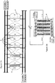
- a reactor e.g. comprises six stacks 5 as shown in Figure 2a , one of them can be separated forcathode or anode regeneration at a time, as shown in Figure 1 .
- this regeneration can be performed during the usual process, namely during dye suspension preparation, so that reduction can be performed with all stacks together.
- the cathodes have to be regenerated also the anode quality may suffer from use. Therefore also the anodes are cleaned although preferably separate from cathode cleaning and at longer intervals. Separate cleaning of cathodes and anodes allows better adaptation of the cleaning parameters.
- the electrochemical reactor is provided with means for supplying cleaning solutions to the stacks 5 of electrolytic cells or rather the electrolytic cells 4 themselves.
- These means comprise at least one cleaning medium supply pipe 61 for supplying cleaning/regeneration solutions to the cathode or anode and - on the side of the electrolytic cell opposite to the inlet - at least one cleaning medium removal pipe 62 for removing acidic cleaning solutions and water and preferably also a basic solution.
- These cleaning medium supply pipes 61 can be bypasses of a catholyte supply pipe 151 and an anolyte supply pipe 31, i.e.
- the one or more cleaning medium supply pipes 61 are connected to acid vessels 63a for supplying acid, and optionally to base vessels 63b for supplying base, as well as to a water line supplying deionized water.
- the one or more cleaning medium removal pipes 62 are either directly fed to a waste water treatment plant (WWTP) or to waste water vessels for storing waste water.
- WWTP waste water treatment plant
- the cleaning solutions are circulated for some time, i.e. until their pollution reaches an undesired level.
- the cleaning medium removal pipe 62 is connected to a vessel 63a, 63b via cleaning medium circulation means 64.
- the cleaning medium circulation means equipped with one or more particle filters and/or adsorption filters, preferably just downstream the electrolytic cells.
- Cleaning or regenerating, respectively, a particulate electrode or both electrodes in an electrochemical reactor of the present invention comprises washing the cathode and/or anode compartments 41, 42, in particular the bed or the particulate electrode, respectively, with strong acids (pK ⁇ 1) by circulating the acidic solution through the compartments 41, 42, in particular the electrode bed, followed by washing the compartment(s) 41, 42, in particular the bed with water, optionally and preferably after having washed the acid treated compartment(s) 41, 42 with a basic solution, preferably caustic soda, for more efficient acid and electrode contamination removal.
- a basic solution preferably caustic soda
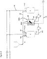
- Figure 3 shows the core of an electrochemical reactor of the present invention with only one electrolytic cell 4 for clarity reasons and with an inlet 11 for dye in solid or suspended form, i.e. transferred from a first vessel 2.
- An assembly of six stacks is shown schematically in Figure 2a , and one stack more in detail with five electrolytic cells is shown in Figure 2b . All stacks 5 and all electrolytic cells 4 are connected in parallel.
- the main vessel 1 is provided with a main suspension circulation loop 14 comprising a main suspension circulation pump P03 and preferably an ultrasound apparatus 141 for circulating the suspension thereby improving its homogeneity.
- the main suspension circulation loop 14 When the suspension has been circulated for some time (dependent on the quality of the dye, i.e. its particle size and particle distribution) the main suspension circulation loop 14 is closed and the valve to the catholyte outlet 12 is opened.
- the catholyte is then circulated through catholyte circulation loop 15 by pumping it by the catholyte pump P01 via catholyte supply pipe 151 through a further optional ultrasound apparatus 154, a particle filter 152 for removing oversized particles if still present and a catholyte heating means (heat exchanger) 153 via catholyte inlet 411 into the cathode compartment 41 of the electrolytic cell 4 separated from the anode compartment 42 by a separator 43, preferably a semipermeable membrane.
- the catholyte After having passed the cathode, the catholyte is returned to the main vessel 1 via reduced catholyte outlet 412a, reduced catholyte return pipe 412b and reduced catholyte inlet 13. As indicated by reference numbers 413a and 413b, in a preferred embodiment the catholyte direction can be inverted.
- An anolyte is supplied to anolyte vessel 3 via anolyte supply pipe 31 or - once the reduction has been started - anolyte inlet 35 and supplied to the anolyte compartment via anolyte outlet 32, anolyte pump P02, anolyte heating means 331 and anolyte inlet 421 into the anode compartment 42. Having left the anode compartment 42 via anolyte outlet 422a, the anolyte is recirculated to anolyte vessel 3 via anolyte return pipe 422b and anolyte inlet 35.
- an adsorption filter 332 is provided within the anolyte circuit. This filter 332 can be placed anywhere, however it is preferably placed just before the anolyte heating means 331 since there the temperature is lowest and thus adsorption best.
- All vessels are in addition provided with supply means for nitrogen, caustic soda and optionally further supply means as well as with degassing means and solution withdrawal lines for the withdrawal of the leuco dye or the anolyte in case of anode cleaning.
- FIG 2a shows schematically 6 stacks, all connected in parallel. Due to independent anolyte and catholyte supply to each of the stacks, any one thereof can be independently shut down for regeneration.
- water is supplied to the separated stack 5 via catholyte inlet 411, removed through reduced catholyte outlet 412a into reduced catholyte return pipe 412b and forwarded to the main vessel or to the first vessel for suspension preparation.
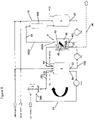
- FIG 4 shows catholyte preparation in the main vessel 1 directly.
- Dye in solid form is introduced into main vessel 1 containing caustic soda in desired concentration as electrolyte (for indigo e.g.caustic soda of 2 to 10 %, preferably about 4 % w/v) via solid dye inlet 11a.
- the main vessel 1 and all pipes and apparatuses that are in contact with leucodye once the reduction process is started are purged with nitrogen (or other inert gas), e.g. introduced into main vessel 1, in order to prevent oxidation of the once reduced dye.
- nitrogen or other inert gas
- the dye suspension is prepared in a first vessel 2.
- this preparation comprises supplying solid dye from solid dye vessel 21a via solid dye inlet 21b into a solution of caustic soda with desired concentration in first vessel 2.
- the first vessel can be provided with a first suspension circulation loop 22, optionally equipped with an ultrasound apparatus 221.
- the dye suspension Once the dye suspension has reached desired homogeneity it is supplied to the main vessel 1 via suspension outlet 23 and dye suspension inlet 11b, driven by pump P05.
- the procedure is as described with regard to Figure 4 .
- a diluted suspension is prepared as described above and subjected to electrolytic reduction in electrolytic cell 4.
- the dye can either be supplemented with further dye in the main vessel 1 or - most preferred - some of the leucodye produced can be transferred from the main vessel 1 via leucodye outlet 16, leucodye return pipe 24 equipped with leucodye return pump P04 and leucodye inlet 241 to the first vessel 2 for being supplemented with further dye.
- the leucodye comprising suspension can then be first processed in the first suspension circulation loop 22 in order to improve its homogeneity before being fed to main vessel 1 and finally to the electrolytic cells as described above.
- an adsorption filter 332 can be provided in the anolyte circulation loop 33. If the anolyte circulation loop 33 comprises a heating means 331, the adsorption filter 332 preferably is provided close to but upstream of the heating means 331 and the heating means 331 is preferably provided upstream of the anode compartment.
- This adsorption filter serves the removal of small molecules that may be present and in general are present in the dye and have been found to migrate through the separator 43, e.g. a semipermeable membrane, and directly or after reaction like polymerization deposit on the anode thereby affecting its activity.
- Suitable adsorption filter materials are e.g. activated carbon and molecular sieves like zeolites. For good anolyte flow through the adsorption filter particle sizes of about 1 to 3 mm, in particular about 2 mm are preferred.
Landscapes
- Chemical & Material Sciences (AREA)
- Engineering & Computer Science (AREA)
- Organic Chemistry (AREA)
- Chemical Kinetics & Catalysis (AREA)
- Electrochemistry (AREA)
- Metallurgy (AREA)
- Materials Engineering (AREA)
- Textile Engineering (AREA)
- Automation & Control Theory (AREA)
- Life Sciences & Earth Sciences (AREA)
- Sustainable Development (AREA)
- Electrolytic Production Of Non-Metals, Compounds, Apparatuses Therefor (AREA)
- Water Treatment By Electricity Or Magnetism (AREA)
Claims (17)
- Ein elektrochemischer Reaktor, geeignet zur Reduktion einer Farbstoffsuspension auf ihre Leukofarbstofflösung, umfassend mindestens vier Elektrolysezellen (4), wobei die Elektrolysezellen in Form von mindestens zwei Stapeln (6) aus mindestens zwei Elektrolysezellen (4) vorgesehen sind, wobei die Stapel (5) parallel geschaltet sind und die Trennung von jeweils mindestens einem Stapel (5) zum Waschen/Regenerieren der Kathode während einer Farbstoffsuspensionszubereitung ermöglichen, wobei das für die Herstellung der Farbstoffsuspension erforderliche Wasser über die Kathoden des zu regenerierenden Stapels zugeführt wird, wodurch der Verlust von Leukofarbstoff vermieden wird, während eine Katholytlösung durch den/die anderen Stapel (5) während der Trennung mindestens eines Stapels (5) zirkuliert, wobei die Elektrolysezellen (4) jedes Stapels (5) parallel geschaltet sind und wobei die Elektrolysezellen einen Kathodenraum (41) und einen Anodenraum (42) umfassen, die durch einen Separator (43) getrennt sind, insbesondere einen Separator, der eine semipermeable Membran umfasst, wobei der Kathodenraum (41) eine Vielzahl von frei schwebenden leitfähigen Körnchen umfasst, insbesondere nicht kugelförmige Granulate, die mit einem Leiter in Kontakt stehen, der zumindest die dem Separator gegenüberliegende Seitenwand bildet, wobei der Kathodenraum (41) mit einem oberen und einem unteren Gitter versehen ist, wobei die Maschenweite und die Positionierung der Gitter so gewählt sind, dass flüssiger Katholyt durch sie hindurchtreten kann, die Granulate jedoch daran gehindert werden, durch sie hindurchzutreten, so dass sie im Kathodenraum (41) zurückgehalten werden, wobei der Anodenraum (42) eine Wand aufweist, die der gemeinsamen Seitenwand gegenüberliegt, die von einer Elektrode gebildet wird, wobei der Kathodenraum (41) über eine Katholyt-Zuführleitung (151) und eine Katholyt-Rückführleitung (412b) für reduzierten Katholyt mit einem Hauptbehälter (1) verbunden ist, um den Katholyt durch den Kathodenraum (41) zirkulieren zu lassen, und der Anodenraum (42) über eine Anolyt-Zuführleitung (31) und eine Anolyt-Rückführleitung (422b) mit einem Anolyt-Behälter (3) verbunden ist, wobei der Kathodenraum (41) und der Anodenraum (42) auch mit Mitteln zum Zuführen von sauren Reinigungslösungen und Wasser und möglicherweise einer basischen Lösung zum Kathodenraum (41) und zum Anodenraum (42) versehen sind, wobei die Mittel mindestens eine Reinigungsmedium-Zuführleitung (61) und mindestens eine Reinigungsmedium-Abführleitung (62) an gegenüberliegenden Enden des Kathodenraums (41) und des Anodenraums (42) umfassen, um saure Reinigungslösungen und Wasser und vorzugsweise auch eine basische Lösung zuzuführen und abzuführen, wobei die Reinigungsmedium-Zuführleitungen (61) und die Reinigungsmedium-Abführleitungen (62) Abzweigungen der Katholyt-Zuführleitung (151) und/oder der Anolyt-Zuführleitung (31) oder unabhängige Leitungen mit ihren eigenen Ein- und Ausgängen neben denen einer Katholyt-Zirkulationsschleife (15) oder einer Anolyt-Zirkulationsschleife (33) sein können, wobei das mindestens eine Reinigungsmedium-Zufuhrleitung (61) mit mindestens einem Behälter (63a, 63b) zum Zuführen von Säure und optional Base verbunden ist und auch mit einer Wasserleitung verbunden ist, die entionisiertes Wasser bereitstellt, und die mindestens eine Reinigungsmedium-Abfuhrleitung (62) mit einer Abwasserbehandlungsanlage (WWTP) oder einem Abwasserbehälter verbunden ist.
- Der elektrochemische Reaktor nach Anspruch 1, umfassend mindestens 6 Stapel (5) und jeder Stapel 2 bis 10 Elektrolysezellen (4) umfasst, vorzugsweise 4 bis 6 Elektrolysezellen, insbesondere 5 Elektrolysezellen, wobei die mindestens 6 und vorzugsweise 6 Stapel so verbunden sind, dass jederzeit mindestens einer von ihnen und vorzugsweise einer von ihnen getrennt werden kann, um mit Reinigungsmedium oder Wasser versorgt zu werden, während die verbleibenden Stapel so verbunden sind, dass die in den Stapeln und den Verbindungsleitungen enthaltene Katholytlösung durch sie hindurch fliessen kann.
- Der elektrochemische Reaktor nach Anspruch 1 oder 2, umfassend einen ersten Behälter (2) stromaufwärts des Hauptbehälters (1).
- Der elektrochemische Reaktor nach einem der vorhergehenden Ansprüche, wobei der erste Behälter (2) und/oder der Hauptbehälter (1), der zur Herstellung des Katholyten verwendet wird, mit den Kathodenräumen (41) der Elektrolysezellen (4) jedes Stapels (5) verbunden ist/sind, so dass der erste Behälter und/oder der Hauptbehälter von jedem der Stapel (5) unabhängig mit Wasser versorgt werden können.
- Der elektrochemische Reaktor nach einem der vorangehenden Ansprüche, weiter umfassend Zirkulationsmittel (64), die es ermöglichen, die sauren Reinigungslösungen und gegebenenfalls die basische Lösung über den Kathodenraum (41) und/oder den Anodenraum (42) zu zirkulieren, bevor sie abgelassen werden, wobei die Zirkulationsmittel (64) vorzugsweise mindestens einen Partikelfilter und/oder mindestens einen Adsorptionsfilter umfassen.
- Der elektrochemische Reaktor nach einem der vorangehenden Ansprüche, wobei die Reinigungsmedium-Zuführleitungen (61, 62) mit den Katholyt-Zuführleitungen (151) und/oder den Anolyt-Zuführleitungen (31) verbunden sind, die jeden Stapel versorgen.
- Der elektrochemische Reaktor nach einem der vorangehenden Ansprüche, wobei die Anodenräume (42) jedes Stapels mit den Reinigungsmedium- und -wasser-Zuführleitungen (61) so verbunden sind, dass sie individuell gesteuert und beispielsweise gleichzeitig oder vorzugsweise unabhängig von den Kathoderäumen (41) des jeweiligen Stapels (5) gewaschen werden können.
- Der elektrochemische Reaktor nach einem der vorangehenden Ansprüche, wobei zumindest die Richtung des Katholyten umgekehrt werden kann, d. h. der Einlass wird zum Auslass und umgekehrt.
- Der elektrochemische Reaktor nach einem der vorangehenden Ansprüche, wobei der Anodenraum (42) in einer Anolyt-Zirkulationsschleife (33) angeordnet ist, wobei die Anolyt-Zirkulationsschleife mit einem Adsorptionsfilter (332) zur Entfernung von molekularen Verunreinigungen versehen ist.
- Der elektrochemischer Reaktor nach einem der vorangehenden Ansprüche, wobei der Hauptbehälter (1) zur Herstellung eines zu reduzierenden Katholyten dient, indem eine Hauptsuspension durch eine Hauptsuspensions-Zirkulationsschleife (14) zirkuliert wird, die mit einer Hauptsuspensions-Zirkulationspumpe (P03) und vorzugsweise mit einem Ultraschallgerät (141) und gegebenenfalls mit einem Heizmittel, vorzugsweise einem Wärmetauscher, ausgestattet ist, insbesondere um die Temperatur auf beispielsweise etwa 50°C bis 65°C, vorzugsweise etwa 60°C, zu erhöhen.
- Der elektrochemische Reaktor nach einem der vorangehenden Ansprüche, wobei der Hauptbehälter (1) zur Herstellung eines Katholyten einen Katholytauslass (12), eine Katholyt-Zirkulationsschleife (15) mit einer Katholyt-Zuführleitung (151), das mit einer Katholyt-Zuführpumpe (P01) ausgestattet ist, und gegebenenfalls und vorzugsweise mindestens ein Ultraschallgerät (154) umfasst, einen Partikelfilter (152) insbesondere zum Entfernen von Partikeln von >50 bis 100 µm und ein Katholyt-Heizmittel (153), insbesondere zum Erhöhen der Temperatur auf beispielsweise etwa 50°C bis 65°C, wobei die Katholyt-Zirkulationsschleife (15) auch einen Kathodenraum (41) und eine Rücklaufleitung (412b) für reduzierten Katholyt umfasst, das den reduzierten Katholyt über den Einlass für reduzierten Katholyt (13) in den Hauptbehälter (1) zurückführt.
- Der elektrochemische Reaktor nach einem der vorangehenden Ansprüche, umfassend einen ersten Behälter (2) stromaufwärts des Hauptbehälters (1), wobei der erste Behälter (2) eine erste Suspensionszirkulationsschleife (22) umfasst, die mit einer ersten Suspensionszirkulationspumpe und einem Ultraschallgerät (221), vorzugsweise einem zylindrischen Ultraschallgerät, ausgestattet ist.
- Ein Verfahren zum Reinigen von elektrochemischen Zellen, die eine teilchenförmige Kathode eines elektrochemischen Reaktors nach einem der vorangehenden Ansprüche umfassen, wobei das Verfahren die folgenden Schritte umfasst- Entfernen der Katholytlösung mit Ausnahme der Menge, die für die Herstellung der Suspension erforderlich ist, und der Mengen, mit denen die elektrochemischen Zellen und ihre Verbindungsrohre gefüllt sind,- Abtrennen jeweils mindestens eines Stapels (5) zum Waschen/Regenerieren der Kathoden während der Herstellung der Katholyt-Suspension,- Zirkulierenlassen die Katholytlösung durch den/die nicht abgetrennten Stapel (5),- Zuführen von deionisiertem Wasser durch die Kathodenräume des mindestens einen separaten Stapels (5) von Elektrolysezellen (4) im Hauptbehälter (1) oder dem ersten Behälter (2),- Isolieren des mindestens einen separaten Stapels (5) von jeglicher Zubereitung und/oder Zirkulation von Katholyt-Suspension,- Waschen mindestens der Kathodenräume (41) des mindestens einen separaten Stapels (5) mit einer sauren Lösung,- Waschen gegebenenfalls mindestens der Kathodenräume (41) des mindestens einen separaten Stapels (5) mit einer basischen Lösung, dann
Spülen der mit Säure und gegebenenfalls mit Base gewaschenen Kathodenräume (41) des mindestens einen separaten Stapels (5) mit entionisiertem Wasser, bis sie neutral sind,- Zusammenführen des mindestens einen separaten Stapels (5) mit den anderen Stapeln (5) und Beginnen der Katholytreduktion,wobei das Waschen und Spülen durchgeführt wird, indem die Waschlösung oder das Spülwasser an einem Ende der elektrochemischen Zelle (4) zugeführt und am gegenüberliegenden Ende abgezogen wird, undwobei die aus den Räumen entnommenen Waschlösungen und das Spülwasser zu einer Abwasserreinigungsanlage (AWS) oder einem Abwasserbehälter geleitet werden. - Das Verfahren nach Anspruch 13, wobei alle Anoden eines Stapels während der Herstellung einer neuen Charge Katholyt-Suspension gemeinsam, aber getrennt von der Reinigung der Kathoden gereinigt werden, wobei das Waschen der Anoden die folgenden Schritte umfasst:- Entfernen der Katholytlösung, mit Ausnahme der Menge, die für die Herstellung der Suspension erforderlich ist, und der Mengen, mit denen die elektrochemischen Zellen und ihre Verbindungsleitungen gefüllt sind,- Abtrennen jeweils mindestens eines Stapels (5) zum Waschen/Regenerieren der Anoden während der Herstellung der Katholyt-Suspension,- Zirkulierenlassen der Katholytlösung durch alle Stapel (5),- Waschen der Anodenräume (42) des mindestens einen separaten Stapels (5) mit einer sauren Lösung,- gegebenenfalls Waschen der Anodenräume (42) des mindestens einen separaten Stapels (5) mit einer basischen Lösung, dann- Spülen mit Säure und gegebenenfalls mit Base der gewaschenen Anodenräume (42) des mindestens einen separaten Stapels (5) mit entionisiertem Wasser, bis sie neutral sind,- Zusammenführen des mindestens einen separaten Stapels (5) mit den anderen Stapeln (5) und Beginnen der Reduktion des Katholyten,wobei das Waschen und Spülen durchgeführt wird, indem die Waschlösung oder das Spülwasser an einem Ende der Anodenräume zugeführt und am gegenüberliegenden Ende abgezogen wird, undbei dem die aus den Anodenräumen entnommenen Waschlösungen und das Spülwasser einer Abwasserbehandlungsanlage (WWTP) oder einem Abwasserbehälter zugeführt werden.
- Das Verfahren nach Anspruch 13 oder 14, bei dem das Waschen mit starken Säuren mit einem (pK < 1) durchgeführt wird, indem die Säurelösung durch mindestens die Kathodenräume (41) des mindestens einen separaten Stapels (5) zirkuliert wird, gefolgt von einem Spülen der Räume (41) mit Wasser, gegebenenfalls und vorzugsweise nach einem Waschen der Räume (41) mit einer Base, vorzugsweise Natronlauge.
- Das Verfahren nach einem der Ansprüche 13 bis 15, wobei die starke Säure aus der Gruppe ausgewählt ist, die aus HCl, H2SO4, HNO3 und deren Mischungen besteht.
- Das Verfahren nach einem der Ansprüche 13 bis 16, wobei die Katholyt-Suspension eine Indigo-Suspension ist und die Katholyt-Lösung eine Leukoindigo-Lösung ist.
Applications Claiming Priority (3)
| Application Number | Priority Date | Filing Date | Title |
|---|---|---|---|
| CH14782018 | 2018-11-30 | ||
| CH14792018 | 2018-11-30 | ||
| PCT/EP2019/083163 WO2020109595A1 (en) | 2018-11-30 | 2019-11-29 | Electrochemical reactor and its cleaning or regeneration |
Publications (2)
| Publication Number | Publication Date |
|---|---|
| EP3887576A1 EP3887576A1 (de) | 2021-10-06 |
| EP3887576B1 true EP3887576B1 (de) | 2022-12-21 |
Family
ID=68771645
Family Applications (1)
| Application Number | Title | Priority Date | Filing Date |
|---|---|---|---|
| EP19813784.6A Active EP3887576B1 (de) | 2018-11-30 | 2019-11-29 | Elektrochemischer reaktor und dessen reinigung oder regeneration |
Country Status (4)
| Country | Link |
|---|---|
| US (1) | US12104262B2 (de) |
| EP (1) | EP3887576B1 (de) |
| CN (1) | CN113166954B (de) |
| WO (1) | WO2020109595A1 (de) |
Families Citing this family (7)
| Publication number | Priority date | Publication date | Assignee | Title |
|---|---|---|---|---|
| US11753730B2 (en) | 2018-11-30 | 2023-09-12 | Sedo Engineering Sa | Leucodye (such as leucoindigo) as dispersing aid |
| WO2020109583A1 (en) * | 2018-11-30 | 2020-06-04 | Sedo Engineering Sa | By-products (impurity) removal |
| EP4001463A1 (de) * | 2020-11-16 | 2022-05-25 | L'Air Liquide Société Anonyme pour l'Etude et l'Exploitation des Procédés Georges Claude | Elektrolyseanordnung und verfahren |
| EP4046969A1 (de) * | 2021-02-22 | 2022-08-24 | E-Watts Technologies, S.L. | Elektrochemisches reaktorsystem mit mitteln zur wartung und reinigung davon |
| CN114934295A (zh) * | 2022-06-15 | 2022-08-23 | 浙江水熊科技有限公司 | 一种电解水生产设备用电解槽免拆自清洁系统及其自清洁工艺 |
| WO2024159441A1 (en) * | 2023-02-01 | 2024-08-08 | Schaeffler Technologies AG & Co. KG | Electrochemical system and method for regenerating electrochemical system |
| CN116446200B (zh) * | 2023-03-14 | 2025-03-25 | 武汉纺织大学 | 一种基于直接电化学还原的棉织物靛蓝染色方法 |
Family Cites Families (25)
| Publication number | Priority date | Publication date | Assignee | Title |
|---|---|---|---|---|
| US3523880A (en) * | 1967-12-27 | 1970-08-11 | Ionics | Electrolytic cell for removal and recovery of so2 from waste gases |
| GB1239983A (en) | 1968-10-07 | 1971-07-21 | Brown John Constr | Electrochemical processes |
| US3701719A (en) | 1969-03-24 | 1972-10-31 | Pullman Inc | Continuous electrochemical process for reaction of compounds containing aliphatic unsaturation |
| US3966571A (en) | 1974-04-24 | 1976-06-29 | General Motors Corporation | Method of operating a dynamically packed bed electrode electrochemical cell system |
| AT398316B (de) | 1989-06-01 | 1994-11-25 | Verein Zur Foerderung Der Fors | Verfahren zur reduktion von farbstoffen |
| TW251325B (de) | 1993-03-30 | 1995-07-11 | Basf Ag | |
| US5425858A (en) | 1994-05-20 | 1995-06-20 | The Regents Of The University Of California | Method and apparatus for capacitive deionization, electrochemical purification, and regeneration of electrodes |
| EP0738766B1 (de) | 1995-04-20 | 2001-07-25 | Clariant Finance (BVI) Limited | Stabile flüssige Schwefelfarbstoffsuspensionen und Verfahren zu deren Analyse |
| JPH10130876A (ja) * | 1996-11-01 | 1998-05-19 | Kobe Steel Ltd | 電解型オゾン水製造装置及びその再生方法 |
| ATE304075T1 (de) | 1998-11-24 | 2005-09-15 | Walter Marte | Verfahren und apparatur zur reduktion von küpen- und schwefelfarbstoffen |
| DE19962155A1 (de) | 1999-12-22 | 2001-06-28 | Basf Ag | Verfahren zur elektrochemischen Reduktion von Küpenfarbstoffen |
| JP3867913B2 (ja) | 2000-07-06 | 2007-01-17 | アクゾ ノーベル エヌ.ブイ. | 陰極の活性化 |
| US20050121336A1 (en) | 2001-12-20 | 2005-06-09 | Walter Marte | Method and apparatus for electro-catalytical hydrogenation of vat dyes and sulphide dyes |
| TWI351446B (en) * | 2006-06-16 | 2011-11-01 | Toshiba Kk | Cleaning system and cleaning method |
| EP1870494A1 (de) * | 2006-06-23 | 2007-12-26 | ETH Zürich, ETH Transfer | Elektrochemischer Reaktor |
| GB0907795D0 (en) * | 2009-05-07 | 2009-06-17 | Acal Energy Ltd | Fuel cells |
| US20140027301A1 (en) * | 2012-07-26 | 2014-01-30 | Ohio University | Selective reductive electrowinning apparatus and method |
| AU2013351879C1 (en) * | 2012-12-02 | 2019-08-08 | Axine Water Technologies Inc. | Method for imparting filtering capability in electrolytic cell for wastewater treatment |
| CN104812708B (zh) * | 2012-12-03 | 2017-03-08 | 安克信水技术公司 | 使用电化学电池有效处理废水 |
| CN103255642B (zh) | 2012-12-31 | 2015-07-29 | 杭州赛龙化工有限公司 | 连续式靛蓝电化学还原染色工艺 |
| CN105603453A (zh) | 2014-11-24 | 2016-05-25 | 中国科学院大连化学物理研究所 | 一种固态聚合物电解质水电解池的原位再生方法 |
| DE102015202117A1 (de) | 2015-02-06 | 2016-08-11 | Siemens Aktiengesellschaft | Verfahren und Elektrolysesystem zur Kohlenstoffdioxid-Verwertung |
| DE102016203947A1 (de) * | 2016-03-10 | 2017-09-14 | Siemens Aktiengesellschaft | Verfahren und Vorrichtung zur elektrochemischen Herstellung von Synthesegas |
| US11753730B2 (en) | 2018-11-30 | 2023-09-12 | Sedo Engineering Sa | Leucodye (such as leucoindigo) as dispersing aid |
| WO2020109583A1 (en) | 2018-11-30 | 2020-06-04 | Sedo Engineering Sa | By-products (impurity) removal |
-
2019
- 2019-11-29 EP EP19813784.6A patent/EP3887576B1/de active Active
- 2019-11-29 CN CN201980078047.0A patent/CN113166954B/zh active Active
- 2019-11-29 US US17/296,709 patent/US12104262B2/en active Active
- 2019-11-29 WO PCT/EP2019/083163 patent/WO2020109595A1/en not_active Ceased
Also Published As
| Publication number | Publication date |
|---|---|
| US20220056595A1 (en) | 2022-02-24 |
| WO2020109595A1 (en) | 2020-06-04 |
| US12104262B2 (en) | 2024-10-01 |
| EP3887576A1 (de) | 2021-10-06 |
| CN113166954B (zh) | 2024-07-26 |
| CN113166954A (zh) | 2021-07-23 |
Similar Documents
| Publication | Publication Date | Title |
|---|---|---|
| US12104262B2 (en) | Electrochemical reactor and its cleaning or regeneration | |
| US11753730B2 (en) | Leucodye (such as leucoindigo) as dispersing aid | |
| CN101479408B (zh) | 电化学反应器 | |
| AU2000267249A1 (en) | Vanadium electrolyte preparation using asymmetric vanadium reduction cells and use of an asymmetric vanadium reduction cell for rebalancing the state of charge of the electrolytes of an operating vanadium redox battery | |
| CN1408037A (zh) | 可还原染料的电化学还原 | |
| AU621543B2 (en) | Electrochemical reactor for copper removal from barren solutions | |
| CN101260530A (zh) | 用于间接电氧化合成有机物电解再生媒质的装置及工艺 | |
| JP2007536432A (ja) | 多層エキスパンデッドメタル電極を有する電解セル | |
| EP3887577B1 (de) | Entfernung von nebenprodukten (verunreinigungen) | |
| US20050115905A1 (en) | Nitrate removal | |
| JPH1028833A (ja) | ガスから電気化学的に転化可能な不純物を電解的に除去する電解槽及び方法 | |
| US5225054A (en) | Method for the recovery of cyanide from solutions | |
| Campbell et al. | The electrochemical recovery of metals from effluent and process streams | |
| JPH01162789A (ja) | 担体上に担持された金属の回収方法及び装置 | |
| RU2251763C2 (ru) | Приготовление ванадиевого электролита с помощью асимметричных электролизеров восстановления ванадия и использование асимметричного электролизера восстановления ванадия для восстановления баланса состояния заряда электролитов работающей ванадиевой восстановительно-окислительной батареи | |
| JPH11158681A (ja) | セレン含有被処理水の処理方法 | |
| HK1053680A (en) | Method for electrochemically reducing reducible dyes | |
| CA2061780A1 (en) | Method for the recovery of cyanides from solutions |
Legal Events
| Date | Code | Title | Description |
|---|---|---|---|
| STAA | Information on the status of an ep patent application or granted ep patent |
Free format text: STATUS: UNKNOWN |
|
| STAA | Information on the status of an ep patent application or granted ep patent |
Free format text: STATUS: THE INTERNATIONAL PUBLICATION HAS BEEN MADE |
|
| PUAI | Public reference made under article 153(3) epc to a published international application that has entered the european phase |
Free format text: ORIGINAL CODE: 0009012 |
|
| STAA | Information on the status of an ep patent application or granted ep patent |
Free format text: STATUS: REQUEST FOR EXAMINATION WAS MADE |
|
| 17P | Request for examination filed |
Effective date: 20210511 |
|
| AK | Designated contracting states |
Kind code of ref document: A1 Designated state(s): AL AT BE BG CH CY CZ DE DK EE ES FI FR GB GR HR HU IE IS IT LI LT LU LV MC MK MT NL NO PL PT RO RS SE SI SK SM TR |
|
| DAV | Request for validation of the european patent (deleted) | ||
| DAX | Request for extension of the european patent (deleted) | ||
| REG | Reference to a national code |
Ref country code: DE Ref legal event code: R079 Ref document number: 602019023495 Country of ref document: DE Free format text: PREVIOUS MAIN CLASS: C25B0003040000 Ipc: C25B0003250000 |
|
| GRAP | Despatch of communication of intention to grant a patent |
Free format text: ORIGINAL CODE: EPIDOSNIGR1 |
|
| STAA | Information on the status of an ep patent application or granted ep patent |
Free format text: STATUS: GRANT OF PATENT IS INTENDED |
|
| RIC1 | Information provided on ipc code assigned before grant |
Ipc: D06B 23/20 20060101ALI20220629BHEP Ipc: D06P 5/20 20060101ALI20220629BHEP Ipc: D06P 1/22 20060101ALI20220629BHEP Ipc: C25B 15/08 20060101ALI20220629BHEP Ipc: C25B 9/40 20210101ALI20220629BHEP Ipc: C25B 3/25 20210101AFI20220629BHEP |
|
| RIC1 | Information provided on ipc code assigned before grant |
Ipc: D06B 23/20 20060101ALI20220707BHEP Ipc: D06P 5/20 20060101ALI20220707BHEP Ipc: D06P 1/22 20060101ALI20220707BHEP Ipc: C25B 15/08 20060101ALI20220707BHEP Ipc: C25B 15/00 20060101ALI20220707BHEP Ipc: C25B 9/70 20210101ALI20220707BHEP Ipc: C25B 9/40 20210101ALI20220707BHEP Ipc: C25B 3/25 20210101AFI20220707BHEP |
|
| INTG | Intention to grant announced |
Effective date: 20220720 |
|
| GRAS | Grant fee paid |
Free format text: ORIGINAL CODE: EPIDOSNIGR3 |
|
| GRAA | (expected) grant |
Free format text: ORIGINAL CODE: 0009210 |
|
| STAA | Information on the status of an ep patent application or granted ep patent |
Free format text: STATUS: THE PATENT HAS BEEN GRANTED |
|
| AK | Designated contracting states |
Kind code of ref document: B1 Designated state(s): AL AT BE BG CH CY CZ DE DK EE ES FI FR GB GR HR HU IE IS IT LI LT LU LV MC MK MT NL NO PL PT RO RS SE SI SK SM TR |
|
| REG | Reference to a national code |
Ref country code: GB Ref legal event code: FG4D |
|
| REG | Reference to a national code |
Ref country code: CH Ref legal event code: EP |
|
| REG | Reference to a national code |
Ref country code: DE Ref legal event code: R096 Ref document number: 602019023495 Country of ref document: DE |
|
| REG | Reference to a national code |
Ref country code: AT Ref legal event code: REF Ref document number: 1539106 Country of ref document: AT Kind code of ref document: T Effective date: 20230115 |
|
| REG | Reference to a national code |
Ref country code: IE Ref legal event code: FG4D |
|
| REG | Reference to a national code |
Ref country code: LT Ref legal event code: MG9D |
|
| REG | Reference to a national code |
Ref country code: NL Ref legal event code: MP Effective date: 20221221 |
|
| PG25 | Lapsed in a contracting state [announced via postgrant information from national office to epo] |
Ref country code: SE Free format text: LAPSE BECAUSE OF FAILURE TO SUBMIT A TRANSLATION OF THE DESCRIPTION OR TO PAY THE FEE WITHIN THE PRESCRIBED TIME-LIMIT Effective date: 20221221 Ref country code: NO Free format text: LAPSE BECAUSE OF FAILURE TO SUBMIT A TRANSLATION OF THE DESCRIPTION OR TO PAY THE FEE WITHIN THE PRESCRIBED TIME-LIMIT Effective date: 20230321 Ref country code: LT Free format text: LAPSE BECAUSE OF FAILURE TO SUBMIT A TRANSLATION OF THE DESCRIPTION OR TO PAY THE FEE WITHIN THE PRESCRIBED TIME-LIMIT Effective date: 20221221 Ref country code: FI Free format text: LAPSE BECAUSE OF FAILURE TO SUBMIT A TRANSLATION OF THE DESCRIPTION OR TO PAY THE FEE WITHIN THE PRESCRIBED TIME-LIMIT Effective date: 20221221 |
|
| REG | Reference to a national code |
Ref country code: AT Ref legal event code: MK05 Ref document number: 1539106 Country of ref document: AT Kind code of ref document: T Effective date: 20221221 |
|
| PG25 | Lapsed in a contracting state [announced via postgrant information from national office to epo] |
Ref country code: RS Free format text: LAPSE BECAUSE OF FAILURE TO SUBMIT A TRANSLATION OF THE DESCRIPTION OR TO PAY THE FEE WITHIN THE PRESCRIBED TIME-LIMIT Effective date: 20221221 Ref country code: LV Free format text: LAPSE BECAUSE OF FAILURE TO SUBMIT A TRANSLATION OF THE DESCRIPTION OR TO PAY THE FEE WITHIN THE PRESCRIBED TIME-LIMIT Effective date: 20221221 Ref country code: HR Free format text: LAPSE BECAUSE OF FAILURE TO SUBMIT A TRANSLATION OF THE DESCRIPTION OR TO PAY THE FEE WITHIN THE PRESCRIBED TIME-LIMIT Effective date: 20221221 Ref country code: GR Free format text: LAPSE BECAUSE OF FAILURE TO SUBMIT A TRANSLATION OF THE DESCRIPTION OR TO PAY THE FEE WITHIN THE PRESCRIBED TIME-LIMIT Effective date: 20230322 |
|
| P01 | Opt-out of the competence of the unified patent court (upc) registered |
Effective date: 20230321 |
|
| PG25 | Lapsed in a contracting state [announced via postgrant information from national office to epo] |
Ref country code: NL Free format text: LAPSE BECAUSE OF FAILURE TO SUBMIT A TRANSLATION OF THE DESCRIPTION OR TO PAY THE FEE WITHIN THE PRESCRIBED TIME-LIMIT Effective date: 20221221 |
|
| PG25 | Lapsed in a contracting state [announced via postgrant information from national office to epo] |
Ref country code: SM Free format text: LAPSE BECAUSE OF FAILURE TO SUBMIT A TRANSLATION OF THE DESCRIPTION OR TO PAY THE FEE WITHIN THE PRESCRIBED TIME-LIMIT Effective date: 20221221 Ref country code: RO Free format text: LAPSE BECAUSE OF FAILURE TO SUBMIT A TRANSLATION OF THE DESCRIPTION OR TO PAY THE FEE WITHIN THE PRESCRIBED TIME-LIMIT Effective date: 20221221 Ref country code: PT Free format text: LAPSE BECAUSE OF FAILURE TO SUBMIT A TRANSLATION OF THE DESCRIPTION OR TO PAY THE FEE WITHIN THE PRESCRIBED TIME-LIMIT Effective date: 20230421 Ref country code: ES Free format text: LAPSE BECAUSE OF FAILURE TO SUBMIT A TRANSLATION OF THE DESCRIPTION OR TO PAY THE FEE WITHIN THE PRESCRIBED TIME-LIMIT Effective date: 20221221 Ref country code: EE Free format text: LAPSE BECAUSE OF FAILURE TO SUBMIT A TRANSLATION OF THE DESCRIPTION OR TO PAY THE FEE WITHIN THE PRESCRIBED TIME-LIMIT Effective date: 20221221 Ref country code: CZ Free format text: LAPSE BECAUSE OF FAILURE TO SUBMIT A TRANSLATION OF THE DESCRIPTION OR TO PAY THE FEE WITHIN THE PRESCRIBED TIME-LIMIT Effective date: 20221221 Ref country code: AT Free format text: LAPSE BECAUSE OF FAILURE TO SUBMIT A TRANSLATION OF THE DESCRIPTION OR TO PAY THE FEE WITHIN THE PRESCRIBED TIME-LIMIT Effective date: 20221221 |
|
| PG25 | Lapsed in a contracting state [announced via postgrant information from national office to epo] |
Ref country code: SK Free format text: LAPSE BECAUSE OF FAILURE TO SUBMIT A TRANSLATION OF THE DESCRIPTION OR TO PAY THE FEE WITHIN THE PRESCRIBED TIME-LIMIT Effective date: 20221221 Ref country code: PL Free format text: LAPSE BECAUSE OF FAILURE TO SUBMIT A TRANSLATION OF THE DESCRIPTION OR TO PAY THE FEE WITHIN THE PRESCRIBED TIME-LIMIT Effective date: 20221221 Ref country code: IS Free format text: LAPSE BECAUSE OF FAILURE TO SUBMIT A TRANSLATION OF THE DESCRIPTION OR TO PAY THE FEE WITHIN THE PRESCRIBED TIME-LIMIT Effective date: 20230421 Ref country code: AL Free format text: LAPSE BECAUSE OF FAILURE TO SUBMIT A TRANSLATION OF THE DESCRIPTION OR TO PAY THE FEE WITHIN THE PRESCRIBED TIME-LIMIT Effective date: 20221221 |
|
| REG | Reference to a national code |
Ref country code: DE Ref legal event code: R097 Ref document number: 602019023495 Country of ref document: DE |
|
| PLBE | No opposition filed within time limit |
Free format text: ORIGINAL CODE: 0009261 |
|
| STAA | Information on the status of an ep patent application or granted ep patent |
Free format text: STATUS: NO OPPOSITION FILED WITHIN TIME LIMIT |
|
| PG25 | Lapsed in a contracting state [announced via postgrant information from national office to epo] |
Ref country code: DK Free format text: LAPSE BECAUSE OF FAILURE TO SUBMIT A TRANSLATION OF THE DESCRIPTION OR TO PAY THE FEE WITHIN THE PRESCRIBED TIME-LIMIT Effective date: 20221221 |
|
| 26N | No opposition filed |
Effective date: 20230922 |
|
| PG25 | Lapsed in a contracting state [announced via postgrant information from national office to epo] |
Ref country code: SI Free format text: LAPSE BECAUSE OF FAILURE TO SUBMIT A TRANSLATION OF THE DESCRIPTION OR TO PAY THE FEE WITHIN THE PRESCRIBED TIME-LIMIT Effective date: 20221221 |
|
| PG25 | Lapsed in a contracting state [announced via postgrant information from national office to epo] |
Ref country code: MC Free format text: LAPSE BECAUSE OF FAILURE TO SUBMIT A TRANSLATION OF THE DESCRIPTION OR TO PAY THE FEE WITHIN THE PRESCRIBED TIME-LIMIT Effective date: 20221221 |
|
| PG25 | Lapsed in a contracting state [announced via postgrant information from national office to epo] |
Ref country code: LU Free format text: LAPSE BECAUSE OF NON-PAYMENT OF DUE FEES Effective date: 20231129 |
|
| GBPC | Gb: european patent ceased through non-payment of renewal fee |
Effective date: 20231129 |
|
| PG25 | Lapsed in a contracting state [announced via postgrant information from national office to epo] |
Ref country code: MC Free format text: LAPSE BECAUSE OF FAILURE TO SUBMIT A TRANSLATION OF THE DESCRIPTION OR TO PAY THE FEE WITHIN THE PRESCRIBED TIME-LIMIT Effective date: 20221221 Ref country code: LU Free format text: LAPSE BECAUSE OF NON-PAYMENT OF DUE FEES Effective date: 20231129 |
|
| REG | Reference to a national code |
Ref country code: IE Ref legal event code: MM4A |
|
| PG25 | Lapsed in a contracting state [announced via postgrant information from national office to epo] |
Ref country code: IE Free format text: LAPSE BECAUSE OF NON-PAYMENT OF DUE FEES Effective date: 20231129 |
|
| PG25 | Lapsed in a contracting state [announced via postgrant information from national office to epo] |
Ref country code: GB Free format text: LAPSE BECAUSE OF NON-PAYMENT OF DUE FEES Effective date: 20231129 |
|
| PG25 | Lapsed in a contracting state [announced via postgrant information from national office to epo] |
Ref country code: FR Free format text: LAPSE BECAUSE OF NON-PAYMENT OF DUE FEES Effective date: 20231130 |
|
| PG25 | Lapsed in a contracting state [announced via postgrant information from national office to epo] |
Ref country code: IE Free format text: LAPSE BECAUSE OF NON-PAYMENT OF DUE FEES Effective date: 20231129 Ref country code: GB Free format text: LAPSE BECAUSE OF NON-PAYMENT OF DUE FEES Effective date: 20231129 Ref country code: FR Free format text: LAPSE BECAUSE OF NON-PAYMENT OF DUE FEES Effective date: 20231130 |
|
| PG25 | Lapsed in a contracting state [announced via postgrant information from national office to epo] |
Ref country code: BG Free format text: LAPSE BECAUSE OF FAILURE TO SUBMIT A TRANSLATION OF THE DESCRIPTION OR TO PAY THE FEE WITHIN THE PRESCRIBED TIME-LIMIT Effective date: 20221221 |
|
| PG25 | Lapsed in a contracting state [announced via postgrant information from national office to epo] |
Ref country code: BG Free format text: LAPSE BECAUSE OF FAILURE TO SUBMIT A TRANSLATION OF THE DESCRIPTION OR TO PAY THE FEE WITHIN THE PRESCRIBED TIME-LIMIT Effective date: 20221221 |
|
| PG25 | Lapsed in a contracting state [announced via postgrant information from national office to epo] |
Ref country code: CY Free format text: LAPSE BECAUSE OF FAILURE TO SUBMIT A TRANSLATION OF THE DESCRIPTION OR TO PAY THE FEE WITHIN THE PRESCRIBED TIME-LIMIT; INVALID AB INITIO Effective date: 20191129 |
|
| PG25 | Lapsed in a contracting state [announced via postgrant information from national office to epo] |
Ref country code: HU Free format text: LAPSE BECAUSE OF FAILURE TO SUBMIT A TRANSLATION OF THE DESCRIPTION OR TO PAY THE FEE WITHIN THE PRESCRIBED TIME-LIMIT; INVALID AB INITIO Effective date: 20191129 |
|
| REG | Reference to a national code |
Ref country code: CH Ref legal event code: U11 Free format text: ST27 STATUS EVENT CODE: U-0-0-U10-U11 (AS PROVIDED BY THE NATIONAL OFFICE) Effective date: 20251201 |
|
| PGFP | Annual fee paid to national office [announced via postgrant information from national office to epo] |
Ref country code: DE Payment date: 20251119 Year of fee payment: 7 |
|
| PGFP | Annual fee paid to national office [announced via postgrant information from national office to epo] |
Ref country code: IT Payment date: 20251125 Year of fee payment: 7 |
|
| PGFP | Annual fee paid to national office [announced via postgrant information from national office to epo] |
Ref country code: TR Payment date: 20251124 Year of fee payment: 7 Ref country code: BE Payment date: 20251119 Year of fee payment: 7 |
|
| PGFP | Annual fee paid to national office [announced via postgrant information from national office to epo] |
Ref country code: CH Payment date: 20251201 Year of fee payment: 7 |