EP3892576A1 - Spulenerkennungsmechanismus und spulenaufhänger in einer spulentransportvorrichtung für einen flyer - Google Patents
Spulenerkennungsmechanismus und spulenaufhänger in einer spulentransportvorrichtung für einen flyer Download PDFInfo
- Publication number
- EP3892576A1 EP3892576A1 EP21164190.7A EP21164190A EP3892576A1 EP 3892576 A1 EP3892576 A1 EP 3892576A1 EP 21164190 A EP21164190 A EP 21164190A EP 3892576 A1 EP3892576 A1 EP 3892576A1
- Authority
- EP
- European Patent Office
- Prior art keywords
- bobbin
- full
- hanger
- empty
- sensor light
- Prior art date
- Legal status (The legal status is an assumption and is not a legal conclusion. Google has not performed a legal analysis and makes no representation as to the accuracy of the status listed.)
- Granted
Links
Images


Classifications
-
- B—PERFORMING OPERATIONS; TRANSPORTING
- B65—CONVEYING; PACKING; STORING; HANDLING THIN OR FILAMENTARY MATERIAL
- B65H—HANDLING THIN OR FILAMENTARY MATERIAL, e.g. SHEETS, WEBS, CABLES
- B65H67/00—Replacing or removing cores, receptacles, or completed packages at paying-out, winding, or depositing stations
- B65H67/04—Arrangements for removing completed take-up packages and or replacing by cores, formers, or empty receptacles at winding or depositing stations; Transferring material between adjacent full and empty take-up elements
- B65H67/0405—Arrangements for removing completed take-up packages or for loading an empty core
-
- D—TEXTILES; PAPER
- D01—NATURAL OR MAN-MADE THREADS OR FIBRES; SPINNING
- D01H—SPINNING OR TWISTING
- D01H9/00—Arrangements for replacing or removing bobbins, cores, receptacles, or completed packages at paying-out or take-up stations ; Combination of spinning-winding machine
- D01H9/02—Arrangements for replacing or removing bobbins, cores, receptacles, or completed packages at paying-out or take-up stations ; Combination of spinning-winding machine for removing completed take-up packages and replacing by bobbins, cores, or receptacles at take-up stations; Transferring material between adjacent full and empty take-up elements
- D01H9/04—Doffing arrangements integral with spinning or twisting machines
-
- D—TEXTILES; PAPER
- D01—NATURAL OR MAN-MADE THREADS OR FIBRES; SPINNING
- D01H—SPINNING OR TWISTING
- D01H13/00—Other common constructional features, details or accessories
- D01H13/32—Counting, measuring, recording or registering devices
-
- B—PERFORMING OPERATIONS; TRANSPORTING
- B65—CONVEYING; PACKING; STORING; HANDLING THIN OR FILAMENTARY MATERIAL
- B65H—HANDLING THIN OR FILAMENTARY MATERIAL, e.g. SHEETS, WEBS, CABLES
- B65H63/00—Warning or safety devices, e.g. automatic fault detectors, stop-motions ; Quality control of the package
- B65H63/04—Warning or safety devices, e.g. automatic fault detectors, stop-motions ; Quality control of the package responsive to excessive tension or irregular operation of apparatus
-
- D—TEXTILES; PAPER
- D01—NATURAL OR MAN-MADE THREADS OR FIBRES; SPINNING
- D01H—SPINNING OR TWISTING
- D01H9/00—Arrangements for replacing or removing bobbins, cores, receptacles, or completed packages at paying-out or take-up stations ; Combination of spinning-winding machine
- D01H9/02—Arrangements for replacing or removing bobbins, cores, receptacles, or completed packages at paying-out or take-up stations ; Combination of spinning-winding machine for removing completed take-up packages and replacing by bobbins, cores, or receptacles at take-up stations; Transferring material between adjacent full and empty take-up elements
-
- D—TEXTILES; PAPER
- D01—NATURAL OR MAN-MADE THREADS OR FIBRES; SPINNING
- D01H—SPINNING OR TWISTING
- D01H9/00—Arrangements for replacing or removing bobbins, cores, receptacles, or completed packages at paying-out or take-up stations ; Combination of spinning-winding machine
- D01H9/18—Arrangements for replacing or removing bobbins, cores, receptacles, or completed packages at paying-out or take-up stations ; Combination of spinning-winding machine for supplying bobbins, cores, receptacles, or completed packages to, or transporting from, paying-out or take-up stations ; Arrangements to prevent unwinding of roving from roving bobbins
- D01H9/182—Overhead conveying devices
-
- B—PERFORMING OPERATIONS; TRANSPORTING
- B65—CONVEYING; PACKING; STORING; HANDLING THIN OR FILAMENTARY MATERIAL
- B65H—HANDLING THIN OR FILAMENTARY MATERIAL, e.g. SHEETS, WEBS, CABLES
- B65H2701/00—Handled material; Storage means
- B65H2701/30—Handled filamentary material
- B65H2701/31—Textiles threads or artificial strands of filaments
- B65H2701/311—Slivers
-
- D—TEXTILES; PAPER
- D01—NATURAL OR MAN-MADE THREADS OR FIBRES; SPINNING
- D01H—SPINNING OR TWISTING
- D01H13/00—Other common constructional features, details or accessories
- D01H13/14—Warning or safety devices, e.g. automatic fault detectors, stop motions ; Monitoring the entanglement of slivers in drafting arrangements
Definitions
- the present disclosure relates to a bobbin detection mechanism and a bobbin hanger in a bobbin transport device for a roving frame.
- Japanese Patent Application Publication No. 2000-27041 discloses a bobbin transfer failure detection device that detects a failure of attachment and detachment of full bobbins and empty bobbins by detecting the full bobbins and the empty bobbins with a detection means.
- a bobbin transport device includes bobbin holding devices which can hold the empty bobbins and the full bobbins alternately in a longitudinal direction, and the bobbin holding devices are disposed alternately at different height.
- the bobbin holding devices disposed at upper positions and at lower positions correspond to full bobbin holding devices and empty bobbin holding devices, respectively.
- a detection region for the detection means is set at a region extending in the longitudinal direction where upper end portions or lower end portions of the empty bobbins held by the empty bobbin holding devices are positioned before bobbin replacement.
- the detection means determines whether or not there is an upper end portion, or a lower end portion of an empty bobbin held by an empty bobbin holding device in the detection region. It is described that the bobbin transfer failure detection device can detect an empty bobbin even if the empty bobbin is held in a state where the full bobbins are suspended from the bobbin transport device at the bobbin replacement.
- the full bobbin holding devices and the empty bobbin holding devices are disposed at the different heights, and thus the full bobbins and the empty bobbins need to be transferred at different heights at the doffing operation and the empty bobbin supply operation.
- the device needs to include a mechanism specifically provided for the transfer of the full bobbins, and a mechanism specifically provided for the transfer of the empty bobbins.
- a bobbin exchange device for transferring the full bobbins from the bobbin transport device to another transport line and the empty bobbins from such another transport line to the bobbin transport device, the structure for transferring bobbins in the bobbin exchange device becomes complicated.
- the present disclosure which has been made in light of the above problems, is directed to providing a bobbin detection mechanism and a bobbin hanger in a bobbin transport device for a roving frame that can detect that there is an empty bobbin suspended from the full bobbin hanger even in the configuration in which the full bobbin hangers and empty bobbin hangers are disposed at the same height.
- a bobbin detection mechanism in a bobbin transport device for a roving frame including a plurality of full bobbin hangers for hanging a full bobbin, a plurality of empty bobbin hangers for hanging an empty bobbin, the full bobbin hangers and the empty bobbin hangers being arranged alternately, and a rail member guiding the full bobbin hangers and the empty bobbin hangers.
- Each of the full bobbin hangers includes a full bobbin shaft portion hanging down from the rail member, and a full bobbin vertically movable member contactable with a bobbin mounted on the full bobbin shaft portion and movable to a lowest position relative to the full bobbin shaft portion and to a holding position that is higher than the lowest position, the full bobbin is held by one of the full bobbin hangers with an upward movement of the full bobbin vertically movable member.
- the bobbin detection mechanism includes a full bobbin hanger photoelectric sensor including a full bobbin hanger sensor light emitter configured to emit a sensor light in a bobbin hanger arrangement direction in which the full bobbin hangers and the empty bobbin hangers are arranged, and a full bobbin hanger sensor light receiver configured to receive the sensor light from the full bobbin hanger sensor light emitter, and a full bobbin hanger sensor light shield formed in the full bobbin hanger vertical movable member, and configured to block the sensor light from the full bobbin hanger sensor light emitter.
- the sensor light from the full bobbin hanger sensor light emitter is set at a position so that the sensor light is blocked by the full bobbin hanger sensor light shield when the full bobbin vertically movable member is positioned at the holding position.
- a bobbin hanger used for a bobbin detection mechanism in a bobbin transport device for a roving frame including a bobbin shaft portion on which a bobbin is mounted, and a bobbin vertically movable member movable up and down relative to the bobbin shaft portion.
- the bobbin vertically movable member includes a bobbin hanger sensor light shield, and the bobbin hanger sensor light shield is configured to block a sensor light of a through beam photoelectric sensor provided in the bobbin detection mechanism when the bobbin vertically movable member moves up with the bobbin mounted on the bobbin shaft portion.
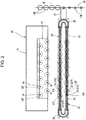
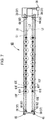
- a roving frame 10 includes a machine frame 11, flyers 12 of a top mount type mounted on the machine frame 11, a bobbin rail 14 supporting a plurality of bobbins 13, and a draft mechanism 15 that stretches a sliver S and lets a roving R out.
- a plurality of bobbin wheels 16 supporting the bobbins 13, respectively, is mounted on the bobbin rail 14.
- the bobbin wheels 16 are arranged on the bobbin rail 14 so that the bobbins 13 are disposed in two rows at regular pitches along the longitudinal direction of the roving frame 10.
- the bobbin wheels 16 in the first row and the bobbin wheels 16 in the second row are displaced at a half pitch to each other in the row direction with respect to the longitudinal direction of the roving frame 10.
- the bobbins 13 having no roving R and the bobbins 13 on which winding of the roving R is completed fully are referred to as empty bobbins 13E and full bobbins 13F, respectively.
- a bobbin rail support device 17 which supports the bobbin rail 14, is disposed on the side of the roving frame 10.
- the bobbin rail support device 17 includes a main body 18 that is reciprocally movable between the bobbin rail 14 of the roving frame 10 and a bobbin transfer position P set in front of the bobbin rail 14, and a bobbin rail support member 19 that supports the bobbin rail 14 of the roving frame 10.
- the bobbin transfer position P is a position where the bobbins 13 are transferred between the bobbin rail support device 17 and a bobbin transport device for a roving frame (hereinafter referred to as a bobbin transport device) 20, which will be described later.
- the bobbin transport device 20 movable up and down is disposed above the bobbin transfer position P.
- the bobbin transport device 20 is configured to transfer the bobbins 13 with the bobbin rail 14 positioned at the bobbin transfer position P.
- the bobbin transport device 20 includes a plurality of bobbin hangers 21 configured to hang the bobbins 13, a rail member 22 configured to guide the bobbin hangers 21, and a rail support member 23 configured to support the rail member 22.
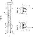
- the bobbin hangers 21 are hangers for holding the bobbins 13. As illustrated in FIG. 2 , the bobbin hangers 21 are disposed at regular pitches on the rail member 22.
- the bobbin hangers 21 includes a plurality of empty bobbin hangers 21E for hanging the empty bobbins 13E, and a plurality of full bobbin hangers 21F for hanging the full bobbins 13F, and the empty bobbin hangers 21E and the full bobbin hangers 21F are arranged alternately on the rail member 22.
- the empty bobbin hangers 21E and the full bobbin hangers 21F are disposed at the same height. The structures of the empty bobbin hangers 21E and the full bobbin hangers 21F will be described later.
- the rail member 22 includes a pair of straight rails 24 disposed in parallel to each other, and arc rails 25, each connecting the ends of the straight rails 24.
- the longitudinal direction of the paired straight rails 24 extends in parallel to the longitudinal direction of the roving frame 10.
- the bobbin hangers 21 are disposed at the regular pitches on the paired straight rails 24 so as to correspond to the bobbin wheels 16 on the bobbin rail 14 at the bobbin transfer position P.
- the arc rails 25 are rails each having an arc shape and connecting the ends of the straight rails 24, and the straight rails 24 and the arc rails 25 permit transporting the bobbin hangers 21.
- the rail support member 23 is a bracket for mounting the rail member 22.
- the paired straight rails 24 and the paired arc rails 25 are mounted to a lower surface of the rail support member 23.
- a bobbin transport line 26 is disposed close to one of ends of the rail member 22.
- the bobbin transport line 26 transports the full bobbins 13F on which roving is wound fully by the roving frame 10 towards a spinning frame (not illustrated) and the empty bobbins 13E to be supplied to the bobbin transport device 20.
- the bobbin transport line 26 is provided with bobbin hangers (not illustrated) for holding the bobbins 13, and the bobbin hangers of the bobbin transport line 26 are transported in one direction.
- a bobbin exchange device 27 is disposed between the bobbin transport device 20 and the bobbin transport line 26.
- the bobbin exchange device 27 is configured to exchange the empty bobbins 13E with the full bobbins 13F, and vice versa, between the bobbin transport device 20 and the bobbin transport line 26.
- a bobbin exchange position at which the empty bobbins 13E and the full bobbin 13F are exchanged is positioned at an intermediate portion of one of the arc rails 25 in the bobbin transport device 20.
- the bobbin exchange device 27 causes the empty bobbin hangers 21E to receive the empty bobbins 13E from the bobbin transport line 26, and causes the full bobbin hangers 21F to transfer the full bobbins 13F to the bobbin transport line 26, thus exchanging the empty bobbins 13E with the full bobbins 13F.
- the bobbin transport device 20 is movable up and down by an elevator device 30.
- the elevator device 30 includes a plurality of pillars 31, support arms 32 movable up and down relative to the pillars 31 and supporting the rail support member 23, elevator mechanisms 33 moving the support arms 32 up and down.
- the plurality of pillars 31 are disposed along the longitudinal direction of the roving frame 10.
- Each of the support arms 32 is provided for each of the pillars 31.
- a horizontal frame 34 extends horizontally towards the roving frame 10 from upper end portions of the pillars 31.
- the support arms 32 and the elevator mechanisms 33 are connected by belts 35.
- Each of the elevator mechanisms 33 includes a motor (not illustrated), and a winding member (not illustrated) for winding each of the belts 35. With the operation of the motor, the support arm 32 moves upward by winding up the belt 35, and the support arm 32 moves downward by rewinding the belt 35.
- the bobbin transport device 20 includes a bobbin detection mechanism 36 to detect whether or not an empty bobbin 13E is hung by the full bobbin hanger 21F.
- the bobbin detection mechanism 36 includes a pair of full bobbin hanger photoelectric sensor 37 so as to correspond to the empty bobbin hangers 21E, the full bobbin hangers 21F, and the pair of straight rails 24.
- each of the full bobbin hanger photoelectric sensors 37 are a through-beam type photoelectric sensor and has a full bobbin hanger sensor light emitter 38 and a full bobbin hanger sensor light receiver 39 receiving a sensor light L from the light emitter 38.
- the full bobbin hanger sensor light emitter 38 is disposed on one end of the rail support member 23 and the full bobbin hanger sensor light receiver 39 is disposed on the other end of the rail support member 23.
- the full bobbin hanger sensor light emitter 38 emits light from a side of the full bobbin hangers 21F and the empty bobbin hangers 21E in a hanger arrangement direction in which the full bobbin hangers 21F and the empty bobbin hangers 21E are arranged and that extends in parallel to the straight rails 24.
- the full bobbin hanger photoelectric sensor 37 is connected to a control device 28.
- the control device 28 controls the bobbin transport device 20 and the elevator device 30.
- the position of the sensor light L of the full bobbin hanger photoelectric sensor 37 is a position close to the bobbin hangers 21. Even when there is one empty bobbin 13E hung by a large number of the full bobbin hangers 21F, the sensor light L is blocked.
- the control device 28 detects blockage of the sensor light L, the control device 28 detects that there is an empty bobbin 13E hung by any of the full bobbin hangers 21F.
- the sensor light L from the full bobbin hanger sensor light emitter 38 is set at a height to which a vertically movable member 49 described later moves up when the empty bobbin 13E is hung by the full bobbin hanger 21F.
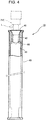
- each of the bobbins 13 includes a bobbin body 40 having a tubular shape.
- An inclined surface 41 that is inclined relative to the axial direction of the bobbin 13 is formed in an opening of the bobbin body 40.
- the bobbin body 40 includes a first inner peripheral surface 42 continuous with the inclined surface 41, a second inner peripheral surface 43 having an inner diameter greater than that of the first inner peripheral surface 42, and a stepped surface 44 between the first inner peripheral surface 42 and the second inner peripheral surface 43.
- the empty bobbins 13E become the full bobbins 13F with the roving R wound on the outer peripheral surface of the bobbin body 40.
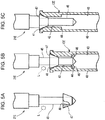
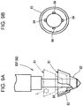
- each of the empty bobbin hangers 21E includes a shaft portion 45 to be inserted into the empty bobbin 13E, an engaging section 46 in a distal end portion of the shaft portion 45 to project out from the shaft portion 45 and be retracted therein in a radial direction of the shaft portion 45, and a vertically movable member 47 to move up and down relative to the shaft portion 45.
- the shaft portion 45 corresponds to the bobbin shaft portion and the empty bobbin shaft portion, and is hung down from the rail member 22.
- the vertically movable member 47 has a circular truncated cone shape having the area of an upper surface greater than that of a lower surface, and has, in the center thereof, a through hole 48 through which the shaft portion 45 is inserted.
- the upward and downward movements of the vertically movable member 47 cause the engaging section 46 to project out and retract.
- the engaging section 46 does not project out from the shaft portion 45.
- the lowest position of the vertically movable member 47 is a position where the vertically movable member 47 lowers the most relative to the shaft portion 45, as illustrated in FIG. 5A .
- FIG. 5B when the vertically movable member 47 is placed in contact with the bobbin 13 and pushed up by the bobbin 13, the vertically movable member 47 moves upward, which causes the engaging section 46 to project out from the shaft portion 45 by the engaging section control mechanism.
- the projection of the engaging section 46 causes the empty bobbin 13E to be held by the empty bobbin hanger 21E.
- the position of the vertically movable member 47 illustrated in FIG. 5B is above the lowest position and corresponds to a holding position where the empty bobbin 13E is held by the empty bobbin hanger 21 E.
- FIG. 5C when the vertically movable member 47 moves upward by being pushed up by the empty bobbin 13E in a state where the empty bobbin 13E is hung by the empty bobbin hanger 21E, the engaging section 46 retracts inside the shaft portion 45, so that empty bobbin 13E may be detached from the empty bobbin hanger 21E.
- the vertically movable member 47 corresponds to the bobbin movable member and the empty bobbin movable member.
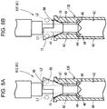
- the vertically movable member 49 of the full bobbin hanger 21F includes a main body 50 and a full bobbin hanger sensor light shield 51 formed integrally with the main body 50.
- the main body 50 corresponds to the vertically movable member 47 of the empty bobbin 21E.
- the shaft portion 45 of the full bobbin hanger 21F corresponds to the bobbin shaft portion and the full bobbin shaft portion
- the vertically movable member 49 corresponds to the bobbin vertically movable member and the full bobbin vertically movable member.
- the bobbin vertically movable member 47 includes the bobbin hanger sensor light shield 51, and the bobbin hanger sensor light shield 51 is configured to block a sensor light L of a through beam photoelectric sensor 37 provided in the bobbin detection mechanism 36 when the bobbin vertically movable member 47 moves up with the bobbin 13 mounted on the bobbin shaft portion 45.
- the full bobbin hanger sensor light shield 51 is a part that blocks the sensor light L when there is an empty bobbin 13E hung by any of the full bobbin hangers 21F.
- the vertically movable member 49 has a generally a circular truncated cone shape, and the dimension of the vertically movable member 49 in the axial direction is two times as large as that of the vertically movable member 47.
- the full bobbin hanger sensor light shield 51 has a cylindrical shape so that the main body 50 is movable up to the upper end of the shaft portion 45.
- the upward and downward movements of the vertically movable member 49 cause the engaging section 46 to project out and retract.
- the vertically movable member 49 functions as a detectable member for detecting whether or not there is an empty bobbin 13E hung. Specifically, as illustrated in FIG. 6A , when the vertically movable member 49 is at the lowest position, the engaging section 46 does not project out from the shaft portion 45.
- the lowest position of the vertically movable member 49 is a position where the vertically movable member 49 lowers the most relative to the shaft portion 45 as illustrated in FIG. 6A . As illustrated in FIG.
- the roving R is wound on each of the bobbins 13.
- the empty bobbin hangers 21E holding the empty bobbins 13E, and the empty bobbins 13E are on standby above the bobbin transfer position P for next winding of the roving R. Since the full bobbin hangers 21F of the bobbin transport device 20 are to hold the full bobbins 13F from the roving frame 10, the full bobbin hangers 21F have no bobbin 13 hung thereby.
- Winding of the roving R by the roving frame 10 stops when the bobbin 13 becomes a full bobbin by winding of the roving R by the roving frame 10. Once the winding by the roving frame 10 stops, the bobbin rail support device 17 moves towards the roving frame 10. With the bobbin rail support member 19 supporting the bobbin rail 14, the bobbin rail support device 17 moves to the bobbin transfer position P. The axes of the full bobbins 13F on the bobbin rail 14 coincide with the axes of the full bobbin hangers 21F at the bobbin transfer position P.
- the elevator mechanism 33 operates so as to move the support arm 32 of the elevator device 30 downward.
- the bobbin transport device 20 moves downward along with the downward movement of the support arm 32.
- the shaft portions 45 of the full bobbin hangers 21F are inserted through the full bobbins 13F, respectively, on the bobbin rail 14 with the downward movement of the bobbin transport device 20, which causes the vertically movable members 49 of the full bobbin hangers 21F to be in contact with the full bobbins 13F and pushed up thereby.
- the engaging sections 46 project out from the respective shaft portions 45.
- the full bobbins 13F may be held by the full bobbin hangers 21F with the engaging section 46 projecting out from the shaft portion 45.
- the elevator mechanism 33 operates so as to move the support arms 32 upward, thereby moving the bobbin transport device 20 upward.
- the full bobbins 13F are hung by the full bobbin hangers 21 F and moved from the bobbin rail 14 to the bobbin transport device 20.
- the bobbin transport device 20 operates so as to move the empty bobbin hangers 21F and the full bobbin hangers 21E by one pitch relative to the rail member 22.
- the axes of the empty bobbins 13E coincide with the axes of the bobbin wheels 16 of the bobbin rail 14.
- the elevator mechanisms 33 operate so as to move the support arms 32 of the elevator devices 30 downward, thereby moving the bobbin transport device 20 downward with the full bobbins 13F and the empty bobbins 13E hung thereby.
- the empty bobbins 13E are mounted on the bobbin wheels 16 with the downward movement of the bobbin transport device 20.
- the vertically movable members 47 of the empty bobbin hangers 21E are in contact with and pushed up by the empty bobbins 13E, which moves the vertically movable members 47 upward.
- the engaging sections 46 projecting out from the shaft portions 45 are retracted inside the shaft portions 45.
- the holding of the empty bobbins 13E by the empty bobbin hangers 21E is released, and the empty bobbins 13E are transferred to the bobbin rail 14. Then, the bobbin transport device 20 moves upward, and the bobbin rail 14 holding the empty bobbins 13E is moved to the roving frame 10 for next winding of the roving R.
- the roving frame 10 starts winding of the roving R on the empty bobbins 13E.
- the bobbin exchange device 27 exchanges the full bobbins 13F with the empty bobbins 13E between the bobbin transport device 20 and the bobbin transport line 26. Specifically, the full bobbins 13F in the bobbin transport device 20 and the empty bobbins 13E transported from the bobbin transport line 26 are exchanged.
- the full bobbins 13F in the bobbin transport device 20 are sent to the bobbin transport line 26, and the empty bobbins 13e transported from the bobbin transport line 26 are sent to the empty bobbin hangers 21E of the bobbin transport device 20.
- the bobbin transport line 26 transports the full bobbins 13F towards the spinning frame.
- the bobbin transport device 20 has the empty bobbins 13E hung only by the empty bobbin hangers 21E, and is on standby for next bobbin replacement.
- the bobbin detection mechanism 36 detects the empty bobbin 13E held by the full bobbin hanger 21F before the full bobbins 13F are transferred to the full bobbin hangers 21F, so that the empty bobbin 13E held by the full bobbin hanger 21F does not hit the full bobbin 13F.
- the vertically movable member 49 is positioned at the lowest position relative to the shaft portion 45, and the full bobbin hanger sensor light shield 51 is positioned lower than the sensor light L, so that the sensor light L is not blocked.
- the sensor light L emitted from the full bobbin hanger sensor light emitter 38 is received by the full bobbin hanger sensor light receiver 39.
- the control device 28 does not detect blockage of the sensor light L, and detects that there is no empty bobbin 13E held by the plurality of full bobbin hangers 21.
- the vertically movable member 49 is placed in contact with the empty bobbin 13E and pushed up by the empty bobbin 13E, which causes the full bobbin hanger sensor light shield 51 to block the sensor light L. Since the sensor light L is blocked, the full bobbin sensor light receiver 39 does not receive the sensor light L, and the control device 28 detects the blockage of the sensor light L, and detects that there is an empty bobbin 13E held by at least one of the plurality of the full bobbin hangers 21F. The control device 28 stops the operation of the bobbin transport device 20 in response to the detection of the empty bobbin 13E, and notifies abnormality.
- the bobbin detection mechanism 36 of the present embodiment offers the following operational effects.
- the bobbin detection mechanism will describe the bobbin detection mechanism according to a second embodiment. In the present embodiment, not only whether there is an empty bobbin held by one of the full bobbin hangers, but also whether or not there is a bobbin held by one of the empty bobbin hangers, are detected. In the following, for the same configurations as those in the first embodiment, the description thereof will not be reiterated, and the same reference numerals will be used.
- empty bobbin hangers 61E and full bobbin hangers 61F are disposed alternately in line in a bobbin transport device 60.
- a full bobbin hanger photoelectric sensor 37 and an empty bobbin hanger photoelectric sensor 62 are disposed with the empty bobbin hangers 61E and the full bobbin hangers 61 F arranged therebetween in line so that a pair of sensor lights L1, L2 are emitted.
- the full bobbin hanger photoelectric sensor 37 includes a full bobbin hanger sensor light emitter 38 that emits a sensor light L1 and a full bobbin hanger sensor light receiver 39 that receives the sensor light L1.
- the empty bobbin hanger photoelectric sensor 62 has the configuration the same as the full bobbin hanger photoelectric sensor 37, and includes an empty bobbin hanger sensor light emitter 63 that emits a sensor light L2 and an empty bobbin hanger sensor light receiver 64 that receives the sensor light L2.
- the empty bobbin hanger photoelectric sensor 62 is connected to the control device 28.
- the empty bobbin hanger photoelectric sensor 62 and the full bobbin hanger photoelectric sensor 37 corresponds to the bobbin detection mechanism 65.
- the height of the sensor light L2 emitted from the empty bobbin hanger sensor light emitter 63 is set at the same height to which a vertically movable member 66, which will be described later, moves up when the empty bobbins 13E are hung by the empty bobbin hangers 61E.
- each of the empty bobbin hangers 61E includes a shaft portion 45, an engaging section 46, and the vertically movable member 66.
- the vertically movable member 66 includes a main body 67 and an empty bobbin hanger sensor light shield 68.
- the empty bobbin hanger sensor light shield 68 is formed in the upper portion of the main body 67, and has a shape that blocks the sensor light L2 of the empty bobbin hanger photoelectric sensor 62 when the empty bobbins 13E are hung by the empty bobbin hangers 61E.
- the vertically movable member 66 has a shape that does not block the sensor light L1 of the full bobbin hanger photoelectric sensor 37 when the empty bobbins 13E are hung by the empty bobbin hangers 61E.
- the empty bobbin hanger sensor light shield 68 of the present embodiment is formed in a shape in which the full bobbin hanger sensor light shield 51 of the first embodiment is cut in half and one of the halves is removed.
- the shaft portion 45 of the empty bobbin hanger 61E corresponds to the bobbin shaft portion and the empty bobbin shaft portion
- the vertically movable member 66 corresponds to the bobbin vertically movable member and the empty bobbin vertically movable member.
- each of the full bobbin hangers 61 F includes the shaft portion 45, the engaging section 46, and the vertically movable member 69.
- the vertically movable member 69 includes a main body 70 and a full bobbin hanger sensor light shield 71.
- the full bobbin hanger sensor light shield 71 is formed in the upper portion of the main body 70, and has a shape that blocks the sensor light L1 of the full bobbin hanger photoelectric sensor 37 when an empty bobbin 13E is hung by one of the full bobbin hanger 61F.
- the vertically movable member 69 has a shape that does not block the sensor light L2 of the empty bobbin hanger photoelectric sensor 62 when an empty bobbin 13E is hung by one of the full bobbin hangers 61F.
- the full bobbin hanger sensor light shield 71 of the present embodiment is formed in a shape in which the full bobbin hanger sensor light shield 51 of the first embodiment is cut in half and one of the halves is removed.
- the shaft portion 45 of the full bobbin hanger 61F corresponds to the bobbin shaft portion and the full bobbin shaft portion
- the vertically movable member 69 corresponds to the bobbin vertically movable member and the full bobbin vertically movable member.
- the full bobbin hanger sensor light shield 71 of the vertically movable member 69 of the full bobbin hanger 61 F blocks the sensor light L1 of the full bobbin hanger photoelectric sensor 37.
- the control device 28 detects the blockage of the sensor light L1, and detects that there is an empty bobbin 13E hung by one of the full bobbin hangers 61F.
- the control device 28 detects the blockage of the sensor light L2, and detects that the empty bobbin 13E is hung by the empty bobbin hangers 61E. In this case, it is possible to detect that the transfer of the empty bobbins 13E to the bobbin rail 14 is incomplete.
- the control device 28 detects that the transfer of the empty bobbins 13E to the bobbin rail 14 is successful.
- the vertically movable member 66 and the vertically movable member 69 have the same shape, but are mounted at the different positions relative to the shaft portions 45. Since there is no need to prepare vertically movable members having a different shape, the production cost for the bobbin hangers 61, i.e., bobbin hangers 61E, 61F, may be reduced.
- the full bobbin hanger 80F of a bobbin hanger 80 is a modification of the full bobbin hanger 21F of the first embodiment.
- the full bobbin hanger 80F includes a vertically movable member 81 movable up and down relative to the shaft portion 45.
- the vertically movable member 81 includes a main body 82 and a full bobbin hanger sensor light shield 83.
- the main body 82 corresponds to the main body 50 of the first embodiment.
- the full bobbin hanger sensor light shield 83 is provided as a separate part from the main body 82, has a hollowed circular truncated cone shape made of a resin, and is detachable from the main body 82.
- a plurality of engaging pins 84 are formed in an end of an inner peripheral surface of the full bobbin hanger sensor light shield 83 on a smaller diameter side thereof.
- Four engaging pins 84 are disposed at regular intervals in the circumferential direction of the inner peripheral surface.
- the present modified embodiment similarly to the first embodiment, it is possible to detect that there is an empty bobbin 13E hung by one of the full bobbin hangers 21F when the full bobbin hanger sensor light shield 83 blocks the sensor light L. Further, since the full bobbin hanger sensor light shield 83 and the main body 82 are separately provided, the main body 82 may be made of a material different from that of the full bobbin hanger sensor light shield 83, so that the weight of the vertically movable member 81 may be reduced. Further, the sensor light L may be blocked by mounting the full bobbin hanger sensor light shield 83 even if the main body 82 is identical to the vertically movable member 47 of the empty bobbin hanger 21. Thus, the existing full bobbin hanger may be used as the full bobbin hanger 80F that blocks the sensor light L.
- a light shield of the vertically movable member in the bobbin hanger has a tubular circular truncated cone shape or a shape in which the tubular circular truncated cone is cut in half and one of the halves is removed, but it is not limited thereto.
- the shape of the light shield of the vertically movable member may be designed freely as long as the light shield can block the sensor light.
- the light shield may have a plate shape.
- the full bobbin hanger sensor light shield is mounted on the main body with the engaging pins, but it is not limited thereto.
- the full bobbin hanger sensor light shield may be mounted on the main body by using a fastener such as a bolt. Mounting of the full bobbin hanger sensor light shield to the main body may be designed freely.
- a bobbin detection mechanism (36) in a bobbin transport device (20) for a roving frame (10) includes a plurality of full bobbin hangers (21F, 61F, 80F), a plurality of empty bobbin hangers (21E, 61E), and a full bobbin hanger photoelectric sensor (37) configured to emit a sensor light (L, L1).
- Each of the full bobbin hangers (21F, 61F, 80F) includes a full bobbin shaft portion, and a full bobbin vertically movable member (49, 69, 81) movable up and down relative to the full bobbin shaft portion (45).
- the bobbin detection mechanism (36) includes a full bobbin hanger sensor light shield (51, 71, 83) formed in the full bobbin hanger vertical movable member (49, 69, 81), and configured to block the sensor light (L, L1) from the full bobbin hanger sensor light emitter (38) when the full bobbin vertically movable member (49, 69, 81) is positioned at the holding position.
Landscapes
- Engineering & Computer Science (AREA)
- Mechanical Engineering (AREA)
- Textile Engineering (AREA)
- Quality & Reliability (AREA)
- Spinning Or Twisting Of Yarns (AREA)
Applications Claiming Priority (1)
| Application Number | Priority Date | Filing Date | Title |
|---|---|---|---|
| JP2020070274A JP7306309B2 (ja) | 2020-04-09 | 2020-04-09 | 粗紡機用ボビン搬送装置におけるボビン検出機構およびボビンハンガー |
Publications (2)
| Publication Number | Publication Date |
|---|---|
| EP3892576A1 true EP3892576A1 (de) | 2021-10-13 |
| EP3892576B1 EP3892576B1 (de) | 2024-04-10 |
Family
ID=75173094
Family Applications (1)
| Application Number | Title | Priority Date | Filing Date |
|---|---|---|---|
| EP21164190.7A Active EP3892576B1 (de) | 2020-04-09 | 2021-03-23 | Spulenerkennungsmechanismus in einer spulentransportvorrichtung für einen flyer |
Country Status (5)
| Country | Link |
|---|---|
| EP (1) | EP3892576B1 (de) |
| JP (1) | JP7306309B2 (de) |
| KR (1) | KR102555850B1 (de) |
| CN (1) | CN113529223B (de) |
| ES (1) | ES2988252T3 (de) |
Families Citing this family (2)
| Publication number | Priority date | Publication date | Assignee | Title |
|---|---|---|---|---|
| JP7760983B2 (ja) * | 2022-10-21 | 2025-10-28 | 株式会社豊田自動織機 | ボビン搬送装置 |
| CN117904759B (zh) * | 2024-01-25 | 2025-09-26 | 德州华源生态科技有限公司 | 一种粗纱机用自循环落纱输送装置 |
Citations (4)
| Publication number | Priority date | Publication date | Assignee | Title |
|---|---|---|---|---|
| US3195833A (en) * | 1962-05-25 | 1965-07-20 | Casablancas High Draft Co Ltd | Bobbin holders for textile machines |
| US3389876A (en) * | 1965-07-30 | 1968-06-25 | Southern Res & Engineering Com | Bobbin holder with wedge member |
| US5987868A (en) * | 1997-09-24 | 1999-11-23 | Zinser Textilmaschinen Gmbh | Monitoring of core mounting for a roving frame |
| JP2000027041A (ja) | 1998-07-09 | 2000-01-25 | Howa Mach Ltd | 繊維機械のボビン受け渡しミス検知方法及び装置並びにボビン搬送装置 |
Family Cites Families (7)
| Publication number | Priority date | Publication date | Assignee | Title |
|---|---|---|---|---|
| JPH0165875U (de) * | 1987-10-19 | 1989-04-27 | ||
| DE4421778C2 (de) * | 1994-06-22 | 1996-11-14 | Zinser Textilmaschinen Gmbh | Vorrichtung zum selbsttätigen Zu- oder Abführen voller Spulen oder leerer Hülsen für eine Textilmaschine |
| JP2002235254A (ja) * | 2001-02-05 | 2002-08-23 | Toyota Industries Corp | 粗紡機及び粗紡機における形状不良ボビン検出装置 |
| DE10251631B4 (de) * | 2002-11-06 | 2005-09-29 | Saurer Gmbh & Co. Kg | Transportsystem für Vorgarnspulen |
| DE102009035393A1 (de) * | 2009-07-30 | 2011-02-03 | Oerlikon Textile Gmbh & Co. Kg | Spulenwechseleinrichtung für eine Vorspinnmaschine |
| CN105442115B (zh) * | 2015-12-30 | 2018-03-16 | 天津宏大纺织机械有限公司 | 一种尾纱清除、尾纱纱管筛选和空满管交换集成装置 |
| CN107142572A (zh) * | 2017-06-22 | 2017-09-08 | 江苏中晖纺织机械有限公司 | 一种落纱粗纱机用空满管交换机构 |
-
2020
- 2020-04-09 JP JP2020070274A patent/JP7306309B2/ja active Active
-
2021
- 2021-03-23 EP EP21164190.7A patent/EP3892576B1/de active Active
- 2021-03-23 ES ES21164190T patent/ES2988252T3/es active Active
- 2021-04-02 CN CN202110360662.XA patent/CN113529223B/zh active Active
- 2021-04-07 KR KR1020210044949A patent/KR102555850B1/ko active Active
Patent Citations (4)
| Publication number | Priority date | Publication date | Assignee | Title |
|---|---|---|---|---|
| US3195833A (en) * | 1962-05-25 | 1965-07-20 | Casablancas High Draft Co Ltd | Bobbin holders for textile machines |
| US3389876A (en) * | 1965-07-30 | 1968-06-25 | Southern Res & Engineering Com | Bobbin holder with wedge member |
| US5987868A (en) * | 1997-09-24 | 1999-11-23 | Zinser Textilmaschinen Gmbh | Monitoring of core mounting for a roving frame |
| JP2000027041A (ja) | 1998-07-09 | 2000-01-25 | Howa Mach Ltd | 繊維機械のボビン受け渡しミス検知方法及び装置並びにボビン搬送装置 |
Also Published As
| Publication number | Publication date |
|---|---|
| CN113529223A (zh) | 2021-10-22 |
| JP7306309B2 (ja) | 2023-07-11 |
| KR20210125925A (ko) | 2021-10-19 |
| ES2988252T3 (es) | 2024-11-19 |
| KR102555850B1 (ko) | 2023-07-13 |
| JP2021167472A (ja) | 2021-10-21 |
| EP3892576B1 (de) | 2024-04-10 |
| CN113529223B (zh) | 2023-03-24 |
Similar Documents
| Publication | Publication Date | Title |
|---|---|---|
| EP3892576B1 (de) | Spulenerkennungsmechanismus in einer spulentransportvorrichtung für einen flyer | |
| US4667807A (en) | Apparatus for taking up bobbins placed on the conveyor | |
| JP2552260B2 (ja) | 粗糸ボビンの搬送方法 | |
| JP2554606B2 (ja) | 粗糸ボビン搬送装置 | |
| US4583358A (en) | Roving-bobbin feeder for spinning machine | |
| US3905184A (en) | Apparatus for simultaneously doffing and donning apparatus | |
| US3633959A (en) | Bobbin grasper | |
| US4036001A (en) | Method and apparatus for doffing and donning bobbins in spinning machine | |
| JPH0214028A (ja) | ボビン取り扱いシステム | |
| CN115369530A (zh) | 一种将接头纱绕到纱管上的装置 | |
| JP7465740B2 (ja) | アダプタ及びパッケージ交換装置 | |
| JP2000027041A (ja) | 繊維機械のボビン受け渡しミス検知方法及び装置並びにボビン搬送装置 | |
| US5170618A (en) | Spinning mill overhead conveyor system having common drive for cleaner and bobbin carriers | |
| JPH0811667B2 (ja) | ボビンの搬送装置 | |
| JP2725007B2 (ja) | 粗糸ボビン搬送装置 | |
| JPS61119730A (ja) | 粗紡機における管替方法及びその装置 | |
| JPH0585658B2 (de) | ||
| JPH0653546B2 (ja) | 粗糸ボビンの搬送方法 | |
| JPS5928052Y2 (ja) | ボビン把持装置 | |
| JPH0515809B2 (de) | ||
| JPH0248653B2 (ja) | Kuriirusochi | |
| JPH0740535Y2 (ja) | 粗糸ボビンの搬送装置 | |
| JPH08134726A (ja) | ボビン搬送体の支持レールの昇降装置 | |
| JPH0748685Y2 (ja) | 粗糸ボビン搬送装置 | |
| JPH07100890B2 (ja) | 篠替機の残糸ボビン取出装置 |
Legal Events
| Date | Code | Title | Description |
|---|---|---|---|
| PUAI | Public reference made under article 153(3) epc to a published international application that has entered the european phase |
Free format text: ORIGINAL CODE: 0009012 |
|
| STAA | Information on the status of an ep patent application or granted ep patent |
Free format text: STATUS: REQUEST FOR EXAMINATION WAS MADE |
|
| 17P | Request for examination filed |
Effective date: 20210323 |
|
| AK | Designated contracting states |
Kind code of ref document: A1 Designated state(s): AL AT BE BG CH CY CZ DE DK EE ES FI FR GB GR HR HU IE IS IT LI LT LU LV MC MK MT NL NO PL PT RO RS SE SI SK SM TR |
|
| P01 | Opt-out of the competence of the unified patent court (upc) registered |
Effective date: 20230519 |
|
| GRAP | Despatch of communication of intention to grant a patent |
Free format text: ORIGINAL CODE: EPIDOSNIGR1 |
|
| STAA | Information on the status of an ep patent application or granted ep patent |
Free format text: STATUS: GRANT OF PATENT IS INTENDED |
|
| INTG | Intention to grant announced |
Effective date: 20231109 |
|
| GRAS | Grant fee paid |
Free format text: ORIGINAL CODE: EPIDOSNIGR3 |
|
| GRAA | (expected) grant |
Free format text: ORIGINAL CODE: 0009210 |
|
| STAA | Information on the status of an ep patent application or granted ep patent |
Free format text: STATUS: THE PATENT HAS BEEN GRANTED |
|
| AK | Designated contracting states |
Kind code of ref document: B1 Designated state(s): AL AT BE BG CH CY CZ DE DK EE ES FI FR GB GR HR HU IE IS IT LI LT LU LV MC MK MT NL NO PL PT RO RS SE SI SK SM TR |
|
| REG | Reference to a national code |
Ref country code: GB Ref legal event code: FG4D |
|
| REG | Reference to a national code |
Ref country code: CH Ref legal event code: EP |
|
| REG | Reference to a national code |
Ref country code: DE Ref legal event code: R096 Ref document number: 602021011467 Country of ref document: DE |
|
| REG | Reference to a national code |
Ref country code: IE Ref legal event code: FG4D |
|
| REG | Reference to a national code |
Ref country code: LT Ref legal event code: MG9D |
|
| REG | Reference to a national code |
Ref country code: NL Ref legal event code: MP Effective date: 20240410 |
|
| REG | Reference to a national code |
Ref country code: AT Ref legal event code: MK05 Ref document number: 1674729 Country of ref document: AT Kind code of ref document: T Effective date: 20240410 |
|
| PG25 | Lapsed in a contracting state [announced via postgrant information from national office to epo] |
Ref country code: NL Free format text: LAPSE BECAUSE OF FAILURE TO SUBMIT A TRANSLATION OF THE DESCRIPTION OR TO PAY THE FEE WITHIN THE PRESCRIBED TIME-LIMIT Effective date: 20240410 |
|
| PG25 | Lapsed in a contracting state [announced via postgrant information from national office to epo] |
Ref country code: NL Free format text: LAPSE BECAUSE OF FAILURE TO SUBMIT A TRANSLATION OF THE DESCRIPTION OR TO PAY THE FEE WITHIN THE PRESCRIBED TIME-LIMIT Effective date: 20240410 |
|
| PG25 | Lapsed in a contracting state [announced via postgrant information from national office to epo] |
Ref country code: IS Free format text: LAPSE BECAUSE OF FAILURE TO SUBMIT A TRANSLATION OF THE DESCRIPTION OR TO PAY THE FEE WITHIN THE PRESCRIBED TIME-LIMIT Effective date: 20240810 |
|
| PG25 | Lapsed in a contracting state [announced via postgrant information from national office to epo] |
Ref country code: BG Free format text: LAPSE BECAUSE OF FAILURE TO SUBMIT A TRANSLATION OF THE DESCRIPTION OR TO PAY THE FEE WITHIN THE PRESCRIBED TIME-LIMIT Effective date: 20240410 |
|
| PG25 | Lapsed in a contracting state [announced via postgrant information from national office to epo] |
Ref country code: HR Free format text: LAPSE BECAUSE OF FAILURE TO SUBMIT A TRANSLATION OF THE DESCRIPTION OR TO PAY THE FEE WITHIN THE PRESCRIBED TIME-LIMIT Effective date: 20240410 Ref country code: FI Free format text: LAPSE BECAUSE OF FAILURE TO SUBMIT A TRANSLATION OF THE DESCRIPTION OR TO PAY THE FEE WITHIN THE PRESCRIBED TIME-LIMIT Effective date: 20240410 |
|
| PG25 | Lapsed in a contracting state [announced via postgrant information from national office to epo] |
Ref country code: GR Free format text: LAPSE BECAUSE OF FAILURE TO SUBMIT A TRANSLATION OF THE DESCRIPTION OR TO PAY THE FEE WITHIN THE PRESCRIBED TIME-LIMIT Effective date: 20240711 |
|
| PG25 | Lapsed in a contracting state [announced via postgrant information from national office to epo] |
Ref country code: PT Free format text: LAPSE BECAUSE OF FAILURE TO SUBMIT A TRANSLATION OF THE DESCRIPTION OR TO PAY THE FEE WITHIN THE PRESCRIBED TIME-LIMIT Effective date: 20240812 |
|
| PG25 | Lapsed in a contracting state [announced via postgrant information from national office to epo] |
Ref country code: AT Free format text: LAPSE BECAUSE OF FAILURE TO SUBMIT A TRANSLATION OF THE DESCRIPTION OR TO PAY THE FEE WITHIN THE PRESCRIBED TIME-LIMIT Effective date: 20240410 |
|
| PG25 | Lapsed in a contracting state [announced via postgrant information from national office to epo] |
Ref country code: PL Free format text: LAPSE BECAUSE OF FAILURE TO SUBMIT A TRANSLATION OF THE DESCRIPTION OR TO PAY THE FEE WITHIN THE PRESCRIBED TIME-LIMIT Effective date: 20240410 |
|
| PG25 | Lapsed in a contracting state [announced via postgrant information from national office to epo] |
Ref country code: LV Free format text: LAPSE BECAUSE OF FAILURE TO SUBMIT A TRANSLATION OF THE DESCRIPTION OR TO PAY THE FEE WITHIN THE PRESCRIBED TIME-LIMIT Effective date: 20240410 |
|
| PG25 | Lapsed in a contracting state [announced via postgrant information from national office to epo] |
Ref country code: PT Free format text: LAPSE BECAUSE OF FAILURE TO SUBMIT A TRANSLATION OF THE DESCRIPTION OR TO PAY THE FEE WITHIN THE PRESCRIBED TIME-LIMIT Effective date: 20240812 Ref country code: PL Free format text: LAPSE BECAUSE OF FAILURE TO SUBMIT A TRANSLATION OF THE DESCRIPTION OR TO PAY THE FEE WITHIN THE PRESCRIBED TIME-LIMIT Effective date: 20240410 Ref country code: NO Free format text: LAPSE BECAUSE OF FAILURE TO SUBMIT A TRANSLATION OF THE DESCRIPTION OR TO PAY THE FEE WITHIN THE PRESCRIBED TIME-LIMIT Effective date: 20240710 Ref country code: LV Free format text: LAPSE BECAUSE OF FAILURE TO SUBMIT A TRANSLATION OF THE DESCRIPTION OR TO PAY THE FEE WITHIN THE PRESCRIBED TIME-LIMIT Effective date: 20240410 Ref country code: IS Free format text: LAPSE BECAUSE OF FAILURE TO SUBMIT A TRANSLATION OF THE DESCRIPTION OR TO PAY THE FEE WITHIN THE PRESCRIBED TIME-LIMIT Effective date: 20240810 Ref country code: HR Free format text: LAPSE BECAUSE OF FAILURE TO SUBMIT A TRANSLATION OF THE DESCRIPTION OR TO PAY THE FEE WITHIN THE PRESCRIBED TIME-LIMIT Effective date: 20240410 Ref country code: GR Free format text: LAPSE BECAUSE OF FAILURE TO SUBMIT A TRANSLATION OF THE DESCRIPTION OR TO PAY THE FEE WITHIN THE PRESCRIBED TIME-LIMIT Effective date: 20240711 Ref country code: FI Free format text: LAPSE BECAUSE OF FAILURE TO SUBMIT A TRANSLATION OF THE DESCRIPTION OR TO PAY THE FEE WITHIN THE PRESCRIBED TIME-LIMIT Effective date: 20240410 Ref country code: BG Free format text: LAPSE BECAUSE OF FAILURE TO SUBMIT A TRANSLATION OF THE DESCRIPTION OR TO PAY THE FEE WITHIN THE PRESCRIBED TIME-LIMIT Effective date: 20240410 Ref country code: AT Free format text: LAPSE BECAUSE OF FAILURE TO SUBMIT A TRANSLATION OF THE DESCRIPTION OR TO PAY THE FEE WITHIN THE PRESCRIBED TIME-LIMIT Effective date: 20240410 Ref country code: RS Free format text: LAPSE BECAUSE OF FAILURE TO SUBMIT A TRANSLATION OF THE DESCRIPTION OR TO PAY THE FEE WITHIN THE PRESCRIBED TIME-LIMIT Effective date: 20240710 |
|
| REG | Reference to a national code |
Ref country code: ES Ref legal event code: FG2A Ref document number: 2988252 Country of ref document: ES Kind code of ref document: T3 Effective date: 20241119 |
|
| REG | Reference to a national code |
Ref country code: DE Ref legal event code: R097 Ref document number: 602021011467 Country of ref document: DE |
|
| PG25 | Lapsed in a contracting state [announced via postgrant information from national office to epo] |
Ref country code: DK Free format text: LAPSE BECAUSE OF FAILURE TO SUBMIT A TRANSLATION OF THE DESCRIPTION OR TO PAY THE FEE WITHIN THE PRESCRIBED TIME-LIMIT Effective date: 20240410 |
|
| PG25 | Lapsed in a contracting state [announced via postgrant information from national office to epo] |
Ref country code: EE Free format text: LAPSE BECAUSE OF FAILURE TO SUBMIT A TRANSLATION OF THE DESCRIPTION OR TO PAY THE FEE WITHIN THE PRESCRIBED TIME-LIMIT Effective date: 20240410 |
|
| PG25 | Lapsed in a contracting state [announced via postgrant information from national office to epo] |
Ref country code: CZ Free format text: LAPSE BECAUSE OF FAILURE TO SUBMIT A TRANSLATION OF THE DESCRIPTION OR TO PAY THE FEE WITHIN THE PRESCRIBED TIME-LIMIT Effective date: 20240410 |
|
| PG25 | Lapsed in a contracting state [announced via postgrant information from national office to epo] |
Ref country code: SK Free format text: LAPSE BECAUSE OF FAILURE TO SUBMIT A TRANSLATION OF THE DESCRIPTION OR TO PAY THE FEE WITHIN THE PRESCRIBED TIME-LIMIT Effective date: 20240410 Ref country code: RO Free format text: LAPSE BECAUSE OF FAILURE TO SUBMIT A TRANSLATION OF THE DESCRIPTION OR TO PAY THE FEE WITHIN THE PRESCRIBED TIME-LIMIT Effective date: 20240410 |
|
| PG25 | Lapsed in a contracting state [announced via postgrant information from national office to epo] |
Ref country code: SM Free format text: LAPSE BECAUSE OF FAILURE TO SUBMIT A TRANSLATION OF THE DESCRIPTION OR TO PAY THE FEE WITHIN THE PRESCRIBED TIME-LIMIT Effective date: 20240410 |
|
| PG25 | Lapsed in a contracting state [announced via postgrant information from national office to epo] |
Ref country code: SM Free format text: LAPSE BECAUSE OF FAILURE TO SUBMIT A TRANSLATION OF THE DESCRIPTION OR TO PAY THE FEE WITHIN THE PRESCRIBED TIME-LIMIT Effective date: 20240410 Ref country code: SK Free format text: LAPSE BECAUSE OF FAILURE TO SUBMIT A TRANSLATION OF THE DESCRIPTION OR TO PAY THE FEE WITHIN THE PRESCRIBED TIME-LIMIT Effective date: 20240410 Ref country code: RO Free format text: LAPSE BECAUSE OF FAILURE TO SUBMIT A TRANSLATION OF THE DESCRIPTION OR TO PAY THE FEE WITHIN THE PRESCRIBED TIME-LIMIT Effective date: 20240410 Ref country code: EE Free format text: LAPSE BECAUSE OF FAILURE TO SUBMIT A TRANSLATION OF THE DESCRIPTION OR TO PAY THE FEE WITHIN THE PRESCRIBED TIME-LIMIT Effective date: 20240410 Ref country code: DK Free format text: LAPSE BECAUSE OF FAILURE TO SUBMIT A TRANSLATION OF THE DESCRIPTION OR TO PAY THE FEE WITHIN THE PRESCRIBED TIME-LIMIT Effective date: 20240410 Ref country code: CZ Free format text: LAPSE BECAUSE OF FAILURE TO SUBMIT A TRANSLATION OF THE DESCRIPTION OR TO PAY THE FEE WITHIN THE PRESCRIBED TIME-LIMIT Effective date: 20240410 |
|
| PLBE | No opposition filed within time limit |
Free format text: ORIGINAL CODE: 0009261 |
|
| STAA | Information on the status of an ep patent application or granted ep patent |
Free format text: STATUS: NO OPPOSITION FILED WITHIN TIME LIMIT |
|
| 26N | No opposition filed |
Effective date: 20250113 |
|
| PG25 | Lapsed in a contracting state [announced via postgrant information from national office to epo] |
Ref country code: SI Free format text: LAPSE BECAUSE OF FAILURE TO SUBMIT A TRANSLATION OF THE DESCRIPTION OR TO PAY THE FEE WITHIN THE PRESCRIBED TIME-LIMIT Effective date: 20240410 |
|
| PGFP | Annual fee paid to national office [announced via postgrant information from national office to epo] |
Ref country code: ES Payment date: 20250403 Year of fee payment: 5 |
|
| PGFP | Annual fee paid to national office [announced via postgrant information from national office to epo] |
Ref country code: CH Payment date: 20250401 Year of fee payment: 5 |
|
| PG25 | Lapsed in a contracting state [announced via postgrant information from national office to epo] |
Ref country code: SE Free format text: LAPSE BECAUSE OF FAILURE TO SUBMIT A TRANSLATION OF THE DESCRIPTION OR TO PAY THE FEE WITHIN THE PRESCRIBED TIME-LIMIT Effective date: 20240410 |
|
| PG25 | Lapsed in a contracting state [announced via postgrant information from national office to epo] |
Ref country code: MC Free format text: LAPSE BECAUSE OF FAILURE TO SUBMIT A TRANSLATION OF THE DESCRIPTION OR TO PAY THE FEE WITHIN THE PRESCRIBED TIME-LIMIT Effective date: 20240410 |
|
| PG25 | Lapsed in a contracting state [announced via postgrant information from national office to epo] |
Ref country code: LU Free format text: LAPSE BECAUSE OF NON-PAYMENT OF DUE FEES Effective date: 20250323 |
|
| GBPC | Gb: european patent ceased through non-payment of renewal fee |
Effective date: 20250323 |
|
| REG | Reference to a national code |
Ref country code: BE Ref legal event code: MM Effective date: 20250331 |
|
| PG25 | Lapsed in a contracting state [announced via postgrant information from national office to epo] |
Ref country code: GB Free format text: LAPSE BECAUSE OF NON-PAYMENT OF DUE FEES Effective date: 20250323 |
|
| PG25 | Lapsed in a contracting state [announced via postgrant information from national office to epo] |
Ref country code: FR Free format text: LAPSE BECAUSE OF NON-PAYMENT OF DUE FEES Effective date: 20250331 |
|
| PG25 | Lapsed in a contracting state [announced via postgrant information from national office to epo] |
Ref country code: BE Free format text: LAPSE BECAUSE OF NON-PAYMENT OF DUE FEES Effective date: 20250331 |
|
| PG25 | Lapsed in a contracting state [announced via postgrant information from national office to epo] |
Ref country code: IE Free format text: LAPSE BECAUSE OF NON-PAYMENT OF DUE FEES Effective date: 20250323 |
|
| REG | Reference to a national code |
Ref country code: CH Ref legal event code: U11 Free format text: ST27 STATUS EVENT CODE: U-0-0-U10-U11 (AS PROVIDED BY THE NATIONAL OFFICE) Effective date: 20260401 |
|
| PGFP | Annual fee paid to national office [announced via postgrant information from national office to epo] |
Ref country code: DE Payment date: 20260128 Year of fee payment: 6 |
|
| PGFP | Annual fee paid to national office [announced via postgrant information from national office to epo] |
Ref country code: IT Payment date: 20260220 Year of fee payment: 6 |