EP4131139A1 - Dispositif capteur et procédé de sécurisation d'une zone de surveillance - Google Patents
Dispositif capteur et procédé de sécurisation d'une zone de surveillance Download PDFInfo
- Publication number
- EP4131139A1 EP4131139A1 EP21189252.6A EP21189252A EP4131139A1 EP 4131139 A1 EP4131139 A1 EP 4131139A1 EP 21189252 A EP21189252 A EP 21189252A EP 4131139 A1 EP4131139 A1 EP 4131139A1
- Authority
- EP
- European Patent Office
- Prior art keywords
- sensor arrangement
- images
- machine
- threshold
- safety
- Prior art date
- Legal status (The legal status is an assumption and is not a legal conclusion. Google has not performed a legal analysis and makes no representation as to the accuracy of the status listed.)
- Granted
Links
Images
Classifications
-
- B—PERFORMING OPERATIONS; TRANSPORTING
- B25—HAND TOOLS; PORTABLE POWER-DRIVEN TOOLS; MANIPULATORS
- B25J—MANIPULATORS; CHAMBERS PROVIDED WITH MANIPULATION DEVICES
- B25J9/00—Program-controlled manipulators
- B25J9/16—Program controls
- B25J9/1674—Program controls characterised by safety, monitoring, diagnostic
- B25J9/1676—Avoiding collision or forbidden zones
-
- G—PHYSICS
- G06—COMPUTING OR CALCULATING; COUNTING
- G06T—IMAGE DATA PROCESSING OR GENERATION, IN GENERAL
- G06T7/00—Image analysis
- G06T7/50—Depth or shape recovery
-
- B—PERFORMING OPERATIONS; TRANSPORTING
- B25—HAND TOOLS; PORTABLE POWER-DRIVEN TOOLS; MANIPULATORS
- B25J—MANIPULATORS; CHAMBERS PROVIDED WITH MANIPULATION DEVICES
- B25J13/00—Controls for manipulators
- B25J13/08—Controls for manipulators by means of sensing devices, e.g. viewing or touching devices
-
- G—PHYSICS
- G01—MEASURING; TESTING
- G01S—RADIO DIRECTION-FINDING; RADIO NAVIGATION; DETERMINING DISTANCE OR VELOCITY BY USE OF RADIO WAVES; LOCATING OR PRESENCE-DETECTING BY USE OF THE REFLECTION OR RERADIATION OF RADIO WAVES; ANALOGOUS ARRANGEMENTS USING OTHER WAVES
- G01S13/00—Systems using the reflection or reradiation of radio waves, e.g. radar systems; Analogous systems using reflection or reradiation of waves whose nature or wavelength is irrelevant or unspecified
- G01S13/86—Combinations of radar systems with non-radar systems, e.g. sonar, direction finder
- G01S13/867—Combination of radar systems with cameras
-
- G—PHYSICS
- G01—MEASURING; TESTING
- G01S—RADIO DIRECTION-FINDING; RADIO NAVIGATION; DETERMINING DISTANCE OR VELOCITY BY USE OF RADIO WAVES; LOCATING OR PRESENCE-DETECTING BY USE OF THE REFLECTION OR RERADIATION OF RADIO WAVES; ANALOGOUS ARRANGEMENTS USING OTHER WAVES
- G01S13/00—Systems using the reflection or reradiation of radio waves, e.g. radar systems; Analogous systems using reflection or reradiation of waves whose nature or wavelength is irrelevant or unspecified
- G01S13/88—Radar or analogous systems specially adapted for specific applications
-
- G—PHYSICS
- G05—CONTROLLING; REGULATING
- G05B—CONTROL OR REGULATING SYSTEMS IN GENERAL; FUNCTIONAL ELEMENTS OF SUCH SYSTEMS; MONITORING OR TESTING ARRANGEMENTS FOR SUCH SYSTEMS OR ELEMENTS
- G05B19/00—Program-control systems
- G05B19/02—Program-control systems electric
- G05B19/18—Numerical control [NC], i.e. automatically operating machines, in particular machine tools, e.g. in a manufacturing environment, so as to execute positioning, movement or co-ordinated operations by means of program data in numerical form
- G05B19/406—Numerical control [NC], i.e. automatically operating machines, in particular machine tools, e.g. in a manufacturing environment, so as to execute positioning, movement or co-ordinated operations by means of program data in numerical form characterised by monitoring or safety
- G05B19/4061—Avoiding collision or forbidden zones
-
- G—PHYSICS
- G06—COMPUTING OR CALCULATING; COUNTING
- G06T—IMAGE DATA PROCESSING OR GENERATION, IN GENERAL
- G06T7/00—Image analysis
- G06T7/20—Analysis of motion
-
- G—PHYSICS
- G06—COMPUTING OR CALCULATING; COUNTING
- G06T—IMAGE DATA PROCESSING OR GENERATION, IN GENERAL
- G06T7/00—Image analysis
- G06T7/20—Analysis of motion
- G06T7/246—Analysis of motion using feature-based methods, e.g. the tracking of corners or segments
- G06T7/248—Analysis of motion using feature-based methods, e.g. the tracking of corners or segments involving reference images or patches
-
- G—PHYSICS
- G06—COMPUTING OR CALCULATING; COUNTING
- G06T—IMAGE DATA PROCESSING OR GENERATION, IN GENERAL
- G06T7/00—Image analysis
- G06T7/70—Determining position or orientation of objects or cameras
-
- G—PHYSICS
- G06—COMPUTING OR CALCULATING; COUNTING
- G06V—IMAGE OR VIDEO RECOGNITION OR UNDERSTANDING
- G06V20/00—Scenes; Scene-specific elements
- G06V20/50—Context or environment of the image
- G06V20/52—Surveillance or monitoring of activities, e.g. for recognising suspicious objects
-
- H—ELECTRICITY
- H04—ELECTRIC COMMUNICATION TECHNIQUE
- H04N—PICTORIAL COMMUNICATION, e.g. TELEVISION
- H04N5/00—Details of television systems
- H04N5/76—Television signal recording
- H04N5/765—Interface circuits between an apparatus for recording and another apparatus
- H04N5/77—Interface circuits between an apparatus for recording and another apparatus between a recording apparatus and a television camera
-
- H—ELECTRICITY
- H04—ELECTRIC COMMUNICATION TECHNIQUE
- H04N—PICTORIAL COMMUNICATION, e.g. TELEVISION
- H04N7/00—Television systems
- H04N7/18—Closed-circuit television [CCTV] systems, i.e. systems in which the video signal is not broadcast
- H04N7/183—Closed-circuit television [CCTV] systems, i.e. systems in which the video signal is not broadcast for receiving images from a single remote source
-
- G—PHYSICS
- G05—CONTROLLING; REGULATING
- G05B—CONTROL OR REGULATING SYSTEMS IN GENERAL; FUNCTIONAL ELEMENTS OF SUCH SYSTEMS; MONITORING OR TESTING ARRANGEMENTS FOR SUCH SYSTEMS OR ELEMENTS
- G05B2219/00—Program-control systems
- G05B2219/30—Nc systems
- G05B2219/40—Robotics, robotics mapping to robotics vision
- G05B2219/40201—Detect contact, collision with human
-
- G—PHYSICS
- G05—CONTROLLING; REGULATING
- G05B—CONTROL OR REGULATING SYSTEMS IN GENERAL; FUNCTIONAL ELEMENTS OF SUCH SYSTEMS; MONITORING OR TESTING ARRANGEMENTS FOR SUCH SYSTEMS OR ELEMENTS
- G05B2219/00—Program-control systems
- G05B2219/30—Nc systems
- G05B2219/40—Robotics, robotics mapping to robotics vision
- G05B2219/40442—Voxel map, 3-D grid map
-
- G—PHYSICS
- G05—CONTROLLING; REGULATING
- G05B—CONTROL OR REGULATING SYSTEMS IN GENERAL; FUNCTIONAL ELEMENTS OF SUCH SYSTEMS; MONITORING OR TESTING ARRANGEMENTS FOR SUCH SYSTEMS OR ELEMENTS
- G05B2219/00—Program-control systems
- G05B2219/30—Nc systems
- G05B2219/49—Nc machine tool, till multiple
- G05B2219/49141—Detect near collision and slow, stop, inhibit movement tool
-
- G—PHYSICS
- G05—CONTROLLING; REGULATING
- G05B—CONTROL OR REGULATING SYSTEMS IN GENERAL; FUNCTIONAL ELEMENTS OF SUCH SYSTEMS; MONITORING OR TESTING ARRANGEMENTS FOR SUCH SYSTEMS OR ELEMENTS
- G05B2219/00—Program-control systems
- G05B2219/30—Nc systems
- G05B2219/49—Nc machine tool, till multiple
- G05B2219/49143—Obstacle, collision avoiding control, move so that no collision occurs
-
- G—PHYSICS
- G06—COMPUTING OR CALCULATING; COUNTING
- G06T—IMAGE DATA PROCESSING OR GENERATION, IN GENERAL
- G06T2200/00—Indexing scheme for image data processing or generation, in general
- G06T2200/04—Indexing scheme for image data processing or generation, in general involving 3D image data
-
- G—PHYSICS
- G06—COMPUTING OR CALCULATING; COUNTING
- G06T—IMAGE DATA PROCESSING OR GENERATION, IN GENERAL
- G06T2207/00—Indexing scheme for image analysis or image enhancement
- G06T2207/10—Image acquisition modality
- G06T2207/10004—Still image; Photographic image
- G06T2207/10012—Stereo images
-
- G—PHYSICS
- G06—COMPUTING OR CALCULATING; COUNTING
- G06T—IMAGE DATA PROCESSING OR GENERATION, IN GENERAL
- G06T2207/00—Indexing scheme for image analysis or image enhancement
- G06T2207/10—Image acquisition modality
- G06T2207/10016—Video; Image sequence
-
- G—PHYSICS
- G06—COMPUTING OR CALCULATING; COUNTING
- G06T—IMAGE DATA PROCESSING OR GENERATION, IN GENERAL
- G06T2207/00—Indexing scheme for image analysis or image enhancement
- G06T2207/10—Image acquisition modality
- G06T2207/10028—Range image; Depth image; 3D point clouds
-
- G—PHYSICS
- G06—COMPUTING OR CALCULATING; COUNTING
- G06T—IMAGE DATA PROCESSING OR GENERATION, IN GENERAL
- G06T2207/00—Indexing scheme for image analysis or image enhancement
- G06T2207/30—Subject of image; Context of image processing
- G06T2207/30196—Human being; Person
-
- G—PHYSICS
- G06—COMPUTING OR CALCULATING; COUNTING
- G06T—IMAGE DATA PROCESSING OR GENERATION, IN GENERAL
- G06T2207/00—Indexing scheme for image analysis or image enhancement
- G06T2207/30—Subject of image; Context of image processing
- G06T2207/30232—Surveillance
Definitions
- the invention relates to a sensor arrangement and a method for securing a surveillance area according to the preamble of claims 1 and 14, respectively.
- the primary goal of safety technology is to protect people from sources of danger, such as those presented by machines in an industrial environment.
- the machine is monitored with the help of sensors, and accordingly, if there is a situation where a person threatens to come dangerously close to the machine, an appropriate safety measure is taken.
- 3D sensors are used for monitoring. These initially include 3D cameras in different technologies, for example stereoscopy, triangulation, time of flight or evaluation of the disturbance of passive two-dimensional patterns or of projected lighting patterns. In contrast to a conventional two-dimensional camera, such 3D sensors record images that contain a distance value in their pixels. This depth-resolved or three-dimensional image data is also referred to as a depth map.
- Sensors used in safety technology or for personal protection must work particularly reliably and therefore meet high safety requirements, for example the EN13849 standard for machine safety and the device standard IEC61496 or EN61496 for electro-sensitive protective equipment (ESPE) or IEC61508.
- ESE electro-sensitive protective equipment
- IEC61508 A number of measures must be taken to meet these safety standards, such as reliable electronic evaluation using redundant, diverse electronics, function monitoring or special monitoring of the contamination of optical components.
- the current protection concept provides that protected areas are configured that the operating personnel may not enter while the machine is in operation. If the sensor detects an unauthorized access to the protected area, such as a worker's body, it triggers a safety-related stop of the machine. In some cases, the protection areas are preceded by additional warning fields in order to prevent a person from violating the protection area in good time or to reduce the working speed of the machine as a precaution. In order to cover all conceivable cases, protection zones must be relatively large, so that the system reacts comparatively early, which reduces productivity.
- Protection zones limit cooperation with machines, especially with robots (HRC, human-robot collaboration).
- Relevant standards in this context are, for example, ISO 10218 for industrial robots or ISO 15066 for collaborating robots.
- HRC human-robot collaboration
- safety distances should be configured as small as possible and possibly even adapted to the situation, of course with the requirement that safety is guaranteed.
- ISO 13854, ISO 13855, ISO 13857 deal with the definition of safety distances.
- a problem area in these safety arrangements is the restart of the dangerous machine (e.g. industrial robot) after a safety-related shutdown.
- a restart should take place as quickly as possible and preferably automatically in order to save valuable production time, i.e. to increase the availability of the machine.
- all manual interventions that are not necessary should be avoided.
- a special case in this sense is the restart of a machine after it has been stopped by a safety intervention.
- a manual reset of the protective device is necessary. The machine can only continue to be operated when a person on site has made sure that the danger area is free of people and releases the machine manually, e.g. via a reset button.
- Such a manual restart restricts the productivity of a machine or system in that someone always has to be available to initiate the restart. If the person can only reach the machine with a delay after the safety intervention, the machine will stand still during this time.
- a monitoring area within the meaning of this invention is mostly a spatial area in which there is a potential danger to life and limb of a person, with the danger emanating from the machine.
- the machine itself and its working area thus constitute a danger point. People are not allowed to be in the monitored area, otherwise the risk of an accident is too great.
- a monitored area can also be an airlock or passage area that a person has to pass through in order to get into a danger area.
- a mobile robot such as an autonomous vehicle (AGV), can also pass through this airlock area.
- AGV autonomous vehicle
- At least one 3D camera continuously captures objects in the surveillance area and generates 3D images of the surveillance area.
- Various technologies are known for a 3-D camera, such as a time-of-flight principle with direct time-of-flight measurement of light signals or phase measurement or a distance estimation from brightness or focus positions (depth from focus, depth from defocus) or a triangulation principle in which two camera images of a moving camera or a stereo camera can be correlated with each other, or alternatively an illumination pattern can be correlated with a camera image in order to estimate disparities and calculate distances from them determine.
- the camera is preferably designed to be fail-safe, that is to say designed for a safety-related application, and for this purpose meets the standards mentioned at the outset or corresponding standards in order to protect a dangerous machine.
- a control and evaluation unit evaluates the 3D images and determines the presence or positions of the detected objects, in particular from the received signal from a light receiver of the 3D camera. If the current position is rated as dangerous, for example because an object is actually in the monitoring area and/or is getting too close to a danger point, a safety-oriented reaction of the machine is initiated.
- the control and evaluation unit designates analog circuits or digital evaluation modules of the 3D camera itself or other devices of the sensor arrangement. A minimum configuration of the sensor arrangement is therefore a single 3-D camera with an internal control and evaluation unit.
- the core of the invention is a restart function after triggering a safety-related reaction of the machine, for example a shutdown.
- a buffer storage unit is provided, in which a specific number of 3D images taken last are always stored.
- the buffer memory unit can, for example, be in the form of a ring memory.
- a motion detection unit the previously identified voxels are then examined to determine whether they show position changes in the course of a specified number of further current images that are above a specified threshold. It is thus found out whether the objects or at least partial areas of the objects are moving. This makes it possible to differentiate between static objects and people. So this is a person recognition. It is found that no If a person is or is no longer in the monitoring area, the machine can safely start up again. For this purpose, a restart signal for the machine is output at an output.
- the 3-D data enable the reliable detection of people with the aid of very small movements that a person constantly carries out due to breathing movements, small shifts in weight or the like. Such small movements are also referred to as micro-movements in this application.
- a person detection that takes place in this way is integrated into the sensor arrangement in addition to the fail-safe basic function of impermissible objects in the monitored area.
- This new people detection function is that it can distinguish between static objects and people. This has the particular advantage that the automatic restart made possible by the invention can save a considerable amount of time and thus increase availability in order to achieve the greatest possible productivity of a system or machine. All unnecessary manual interventions are avoided.
- the threshold for motion detection is 10 mm. This value is a compromise between the possible resolution of the 3-D camera, which should be as coarse as possible so that the camera can remain inexpensive, and the desire to detect the smallest movements, such as body movements caused by breathing.
- a person detection signal can be output in a further development of the invention when the motion detection unit has detected a person, ie detects movements that are above the specified threshold.
- the absolute values of the position changes of a identified voxels are summed from image to image and the threshold is a permanently stored voxel threshold in order to output the motion detection signal (person detection signal) and/or to suppress the restart signal if the sum of the absolute values of the position changes is above the voxel threshold.
- the absolute values of the position changes of all identified voxels from image to image are summed up in the motion detection unit and the threshold is a permanently stored summation threshold in order to output the motion detection signal (person detection signal) and/or to suppress the restart signal if the sum of the absolute values of the position changes is above the sum threshold.
- This sum consideration has the advantage that even the smallest changes in position, for example of just a single voxel, are not recognized as movement, but several voxels (ie the sum) must "recognize" the movement.
- the voxel identification is simplified if the 3D camera is designed to record an additional optical feature, e.g. color, brightness, reflectivity, which serves as an additional criterion for identifying the voxels in the voxel identification unit.
- an additional optical feature e.g. color, brightness, reflectivity
- the absolute position of the voxels in relation to a configured protection volume can be evaluated as an additional feature. This can improve the robustness, because it is sufficient if the analysis of micro-movements is only carried out where the configured protective volume is violated.
- the buffer memory unit, the voxel identification unit and the motion detection unit are advantageously parts of the control and evaluation unit. This not only shortens the signal paths, but also increases compactness.
- the sensor arrangement preferably has a safety controller in which at least part of the control and evaluation unit is implemented.
- the control and evaluation functionality is divided into an internal part within the 3D camera and an external part in the safety controller. Both extremes with completely self-sufficient A 3D camera that has this functionality itself and only outputs the safety-related signal, or a 3D camera that only supplies raw measurement signals are conceivable.
- the sensor arrangement preferably includes an additional sensor, in particular a radar sensor, which detects the movements of objects in the monitoring area.
- an additional sensor in particular a radar sensor, which detects the movements of objects in the monitoring area.
- security can be increased, namely by having another sensor with different measurement technology also carry out motion detection.
- a radar sensor has the disadvantage that it cannot provide a position determination, which is irrelevant here, because the position is already determined with the 3D camera.
- the radar sensor only serves to increase security by performing the crucial function of motion detection redundantly and diversely.
- the control and evaluation unit is advantageously designed to be fail-safe.
- variable N in the buffer memory unit is equal to 10 or greater. This is a sensible compromise between fast storage of as few images as possible and accuracy of the reference map due to as many images as possible.
- the continuous acquisition of 3-D images takes place in a fixed time frame.
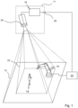
- FIG. 1 shows in a schematic three-dimensional representation the general structure of a sensor arrangement 10 according to the invention with a 3-D camera for recording a depth map in a typical surveillance situation.
- At least one 3D camera 11 continuously captures objects 14 and 16 in its field of view 12 and generates 3D images of the field of view 12.
- Various technologies are known for a 3-D camera, such as a light propagation time principle with direct propagation time measurement of light signals or phase measurement or a distance estimation from brightness or focus positions (depth from focus, depth from defocus) or a triangulation principle in which two camera images a moving camera or a stereo camera can be correlated with each other, or alternatively an illumination pattern can be correlated with a camera image in order to estimate disparities and determine distances from them.
- the 3-D camera 11 is preferably designed to be fail-safe, that is to say designed for a safety-related application, and therefore meets the standards mentioned at the outset or corresponding standards in order to protect a dangerous machine.
- a control and evaluation unit 18 evaluates the 3D images and determines the positions of the detected objects 14 and 16, in particular from the received signal of a light receiver 20 of the 3D camera 11.
- the control and evaluation unit 18 can be implemented in a wide variety of hardware , For example digital components such as microprocessors, ASICs (Application Specific Integrated Circuit), FPGAs (Field Programmable Gate Array), GPUs (Graphics Processing Unit) or mixed forms thereof, which are preferably located in the 3D camera 11, but which can also be internal and external components can be distributed, whereby external components can also be integrated via a network or a cloud, insofar as latencies can be controlled or tolerated. Since a 3-D evaluation, ie the generation of a depth map and its evaluation, is very computationally intensive, an at least partially parallel architecture is preferably formed.
- a monitoring area 22 is defined within the viewing area 12 in which, for example, a person, here object 14 , must not be located, because otherwise the person 14 would come too close to the danger point, ie the machine 16 . If the person 14 nevertheless enters the monitoring area 22 , the current position is assessed as dangerous and a safety-oriented reaction of the machine 16 is initiated via a machine control 24 .
- the control and evaluation unit 18 has a safety output 26 via which a safety signal can be sent to the machine control 24 .
- the control and evaluation unit 18 refers here to analog circuits or digital evaluation components of the 3-D camera 11 itself or other devices sensor arrangement.
- a minimum configuration of the sensor arrangement is therefore a single 3-D camera with an internal control and evaluation unit, as in 1 is shown schematically.
- the core of the invention is a restart function after triggering a safety-related reaction of the machine 16, for example a shutdown.
- a buffer memory unit 28 is provided, for example in the control and evaluation unit 18.
- a specific number N of the last 3D images recorded are continuously stored during operation.
- the buffer memory unit 28 can be designed, for example, in the manner of a ring memory.
- a 3-D reference map of the monitored area 22 is created in the control and evaluation unit 18 from the stored N images.
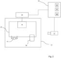
- the situation immediately before the safety-related shutdown is thus virtually recorded. So the configuration as shown in 2 is shown.
- a permissible object 30 for example a pallet loaded with material, in the monitoring area 22.
- the variable N is preferably equal to 10 or greater. This is a sensible compromise between fast storage of as few images as possible and accuracy of the reference map due to as many images as possible.
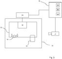
- the 3D camera 11 After switching off, the 3D camera 11 continues to record 3D images continuously. These new 3-D images are further processed together with the reference map in a voxel identification unit 32 and those voxels are identified or labeled whose coordinates deviate from those of the corresponding voxels in the reference map by a predetermined distance.
- this object 14 or rather the partial areas of this object that are in the monitoring area 22, are identified because their position has changed after the safety-related reaction. All other areas or Objects in the monitored area are static and therefore allowed in the monitored area because they did not lead to a safety-related reaction.
- a motion detection unit 34 the previously identified voxels are examined to determine whether they show position changes in the course of a specified number of further current images that are above a specified threshold. It is thus found out whether the objects or at least partial areas of the object 14 are moving. A distinction between static objects 30 and persons 14 is thus possible. So this is a person detection. This works because a person cannot remain static. Even if the person falls in the monitored area and remains lying "motionless", minor movements will still occur solely through breathing, which the sensor arrangement according to the invention identifies.
- the threshold for recognizing an approval is preferably 10 mm. Movements are thus detected that amount to at least a change in position of 10 mm.
- the machine 16 can start up again safely.
- a restart signal for the machine 16 is then output at the output 26 .
- the machine control 24 then allows the machine 16 to start up again.
- a person detection signal can be output in a further development of the invention when the motion detection unit 34 has detected a person, ie detects movements that are above the defined threshold.
- the buffer memory unit 28, the voxel identification unit 32 and the motion detection unit 34 are preferably parts of the control and evaluation unit 18. This not only shortens the signal paths but also increases compactness.
- the control and evaluation unit 18 can be integrated into the 3D camera to further increase compactness.
- the sensor arrangement 10 includes an additional sensor, in particular a radar sensor, which only detects movements of objects in the monitoring area 22 .
- an additional sensor in particular a radar sensor, which only detects movements of objects in the monitoring area 22 .
- the functional reliability which is synonymous with motion detection security, can be increased because a radar sensor with different measurement technology, i.e. diversely redundant, also performs motion detection.
- All of the components of the sensor arrangement 10, and in particular the control and evaluation unit 18 with the buffer memory unit 28, the voxel identification unit 32 and the motion detection unit 34, are preferably designed to be fail-safe.
Landscapes
- Engineering & Computer Science (AREA)
- Physics & Mathematics (AREA)
- Remote Sensing (AREA)
- Radar, Positioning & Navigation (AREA)
- General Physics & Mathematics (AREA)
- Multimedia (AREA)
- Theoretical Computer Science (AREA)
- Computer Vision & Pattern Recognition (AREA)
- Robotics (AREA)
- Mechanical Engineering (AREA)
- Signal Processing (AREA)
- Computer Networks & Wireless Communication (AREA)
- Human Computer Interaction (AREA)
- Electromagnetism (AREA)
- Manufacturing & Machinery (AREA)
- Automation & Control Theory (AREA)
- Emergency Alarm Devices (AREA)
- Alarm Systems (AREA)
Priority Applications (2)
| Application Number | Priority Date | Filing Date | Title |
|---|---|---|---|
| EP21189252.6A EP4131139B1 (fr) | 2021-08-03 | 2021-08-03 | Dispositif capteur et procédé de sécurisation d'une zone de surveillance |
| US17/879,555 US12290939B2 (en) | 2021-08-03 | 2022-08-02 | Sensor arrangement and method for safeguarding a monitored zone |
Applications Claiming Priority (1)
| Application Number | Priority Date | Filing Date | Title |
|---|---|---|---|
| EP21189252.6A EP4131139B1 (fr) | 2021-08-03 | 2021-08-03 | Dispositif capteur et procédé de sécurisation d'une zone de surveillance |
Publications (2)
| Publication Number | Publication Date |
|---|---|
| EP4131139A1 true EP4131139A1 (fr) | 2023-02-08 |
| EP4131139B1 EP4131139B1 (fr) | 2025-11-26 |
Family
ID=77179949
Family Applications (1)
| Application Number | Title | Priority Date | Filing Date |
|---|---|---|---|
| EP21189252.6A Active EP4131139B1 (fr) | 2021-08-03 | 2021-08-03 | Dispositif capteur et procédé de sécurisation d'une zone de surveillance |
Country Status (2)
| Country | Link |
|---|---|
| US (1) | US12290939B2 (fr) |
| EP (1) | EP4131139B1 (fr) |
Families Citing this family (3)
| Publication number | Priority date | Publication date | Assignee | Title |
|---|---|---|---|---|
| KR102722558B1 (ko) * | 2022-07-01 | 2024-10-29 | 주식회사 코너스 | 작업현장 위험감지 시스템 |
| EP4679381A1 (fr) * | 2024-07-12 | 2026-01-14 | Sick Ag | Système de capteur |
| CN121033758B (zh) * | 2025-08-12 | 2026-06-19 | 西安科技大学 | 一种基于深度学习三维点云入侵检测方法及装置 |
Citations (3)
| Publication number | Priority date | Publication date | Assignee | Title |
|---|---|---|---|---|
| US20150294496A1 (en) * | 2014-04-14 | 2015-10-15 | GM Global Technology Operations LLC | Probabilistic person-tracking using multi-view fusion |
| EP3611422A1 (fr) * | 2018-08-15 | 2020-02-19 | Sick Ag | Dispositif capteur et procédé de sécurisation d'une zone de surveillance |
| EP3715065A1 (fr) * | 2014-02-04 | 2020-09-30 | Microsoft Technology Licensing, LLC | Commande d'un robot en présence d'un objet mobile |
Family Cites Families (11)
| Publication number | Priority date | Publication date | Assignee | Title |
|---|---|---|---|---|
| DE102013106514B3 (de) * | 2013-06-21 | 2014-10-30 | Pilz Gmbh & Co. Kg | Vorrichtung und Verfahren zum Absichern einer automatisiert arbeitenden Maschine |
| EP3421189B1 (fr) * | 2017-06-28 | 2019-05-22 | Sick AG | Procédé de surveillance d'une machine |
| EP3572971B1 (fr) * | 2018-05-22 | 2021-02-24 | Sick Ag | Protection d'une zone de surveillance à au moins une machine |
| EP3578320B1 (fr) * | 2018-06-07 | 2021-09-15 | Sick Ag | Configurer un endroit dangereux surveillé par un capteur tridimensionnel |
| EP3578319B1 (fr) * | 2018-06-07 | 2021-01-20 | Sick Ag | Procédé de sécurisation d'un endroit dangereux |
| DE202018103869U1 (de) * | 2018-07-06 | 2019-10-10 | Sick Ag | 3D-Sensor zum Überwachen eines Überwachungsbereichs |
| DE102018116371B4 (de) * | 2018-07-06 | 2020-08-06 | Sick Ag | 3D-Sensor und Verfahren zum Überwachen eines Überwachungsbereichs |
| JP6916157B2 (ja) * | 2018-10-23 | 2021-08-11 | ファナック株式会社 | 人と協働作業を行うロボットシステム、及びロボット制御方法 |
| US11969898B2 (en) * | 2018-12-17 | 2024-04-30 | Datalogic Ip Tech S.R.L. | Multi-sensor optimization of automatic machines to prevent safety issues |
| EP4076260B1 (fr) * | 2019-12-19 | 2025-07-09 | Covidien LP | Systèmes et procédés de réduction des collisions d'un système robotique |
| DE102021208279B4 (de) * | 2021-07-30 | 2023-03-16 | Fraunhofer-Gesellschaft zur Förderung der angewandten Forschung eingetragener Verein | Integration einer Risikobeurteilung einer Kollision zwischen einem robotischen Gerät und einer menschlichen Bedienperson |
-
2021
- 2021-08-03 EP EP21189252.6A patent/EP4131139B1/fr active Active
-
2022
- 2022-08-02 US US17/879,555 patent/US12290939B2/en active Active
Patent Citations (3)
| Publication number | Priority date | Publication date | Assignee | Title |
|---|---|---|---|---|
| EP3715065A1 (fr) * | 2014-02-04 | 2020-09-30 | Microsoft Technology Licensing, LLC | Commande d'un robot en présence d'un objet mobile |
| US20150294496A1 (en) * | 2014-04-14 | 2015-10-15 | GM Global Technology Operations LLC | Probabilistic person-tracking using multi-view fusion |
| EP3611422A1 (fr) * | 2018-08-15 | 2020-02-19 | Sick Ag | Dispositif capteur et procédé de sécurisation d'une zone de surveillance |
Non-Patent Citations (1)
| Title |
|---|
| TIMO MALM ET AL: "Dynamic safety system for collaboration of operators and industrial robots", CENTRAL EUROPEAN JOURNAL OF ENGINEERING, vol. 9, no. 1, 7 March 2019 (2019-03-07), Heidelberg, pages 61 - 71, XP055712921, ISSN: 1896-1541, DOI: 10.1515/eng-2019-0011 * |
Also Published As
| Publication number | Publication date |
|---|---|
| EP4131139B1 (fr) | 2025-11-26 |
| US12290939B2 (en) | 2025-05-06 |
| US20230081003A1 (en) | 2023-03-16 |
Similar Documents
| Publication | Publication Date | Title |
|---|---|---|
| EP3200122B1 (fr) | Capteur optoelectronique et procede de reconnaissance fiable d'objets de taille minimum | |
| EP3011225B1 (fr) | Dispositif et procédé pour protéger une machine fonctionnant de manière automatisée | |
| EP3701340B1 (fr) | Dispositif de surveillance, équipement industriel, procédé de surveillance et programme informatique | |
| EP3611422B1 (fr) | Dispositif capteur et procédé de sécurisation d'une zone de surveillance | |
| DE102010037744B3 (de) | Optoelektronischer Sensor | |
| DE102009031732B3 (de) | Entfernungsmessender optoelektronischer Sensor | |
| EP2023160B1 (fr) | Surveillance spatiale tridimensionnelle dotée d'un mode de configuration pour la détermination des champs de protection | |
| EP3578319B1 (fr) | Procédé de sécurisation d'un endroit dangereux | |
| EP3421189B1 (fr) | Procédé de surveillance d'une machine | |
| EP4131139B1 (fr) | Dispositif capteur et procédé de sécurisation d'une zone de surveillance | |
| DE102012102236A1 (de) | Verfahren und Vorrichtung zum Absichern eines gefährlichen Arbeitsbereichs einer automatisiert arbeitenden Maschine | |
| EP3578320A1 (fr) | Configurer un endroit dangereux surveillé par un capteur tridimensionnel | |
| EP3916286B1 (fr) | Capteur optoélectronique de sécurité et procédé de sécurisation d'une machine | |
| DE102010036775A1 (de) | Entfernungsmessender optoelektronischer Sensor zur Montage an einer Durchgangsöffnung | |
| EP3572971B1 (fr) | Protection d'une zone de surveillance à au moins une machine | |
| EP3575666B1 (fr) | Dispositif de sécurisation d'une zone à risque d'une installation | |
| DE102017111885B4 (de) | Verfahren und System zum Überwachen einer Maschine | |
| DE102016222245A1 (de) | Einrichtung und Verfahren zur Einwirkung auf Gegenstände | |
| EP4102252B1 (fr) | Surveillance sûre d'une zone de protection au moyen d'une caméra tof | |
| DE10245720A1 (de) | Verfahren un Vorrichtung zum Absichern eines Gefahrenbereichs | |
| EP1837586B1 (fr) | Dispositif de surveillance d'une zone dangereuse près d'une machine | |
| EP3588365A1 (fr) | Capteur optoélectronique et procédé d'évaluation sécurisée des données de mesure | |
| EP4290117A1 (fr) | Dispositif de surveillance | |
| DE102019127826B4 (de) | Sicherer optoelektronischer Sensor und Verfahren zum Absichern eines Überwachungsbereichs | |
| EP3893145B1 (fr) | Sécurisation d'un endroit dangereux |
Legal Events
| Date | Code | Title | Description |
|---|---|---|---|
| PUAI | Public reference made under article 153(3) epc to a published international application that has entered the european phase |
Free format text: ORIGINAL CODE: 0009012 |
|
| STAA | Information on the status of an ep patent application or granted ep patent |
Free format text: STATUS: THE APPLICATION HAS BEEN PUBLISHED |
|
| AK | Designated contracting states |
Kind code of ref document: A1 Designated state(s): AL AT BE BG CH CY CZ DE DK EE ES FI FR GB GR HR HU IE IS IT LI LT LU LV MC MK MT NL NO PL PT RO RS SE SI SK SM TR |
|
| STAA | Information on the status of an ep patent application or granted ep patent |
Free format text: STATUS: REQUEST FOR EXAMINATION WAS MADE |
|
| 17P | Request for examination filed |
Effective date: 20230804 |
|
| RBV | Designated contracting states (corrected) |
Designated state(s): AL AT BE BG CH CY CZ DE DK EE ES FI FR GB GR HR HU IE IS IT LI LT LU LV MC MK MT NL NO PL PT RO RS SE SI SK SM TR |
|
| REG | Reference to a national code |
Ref legal event code: R079 Ipc: B25J0009160000 Ref country code: DE Ref legal event code: R079 Ref document number: 502021009274 Country of ref document: DE Free format text: PREVIOUS MAIN CLASS: G06T0001000000 Ipc: B25J0009160000 |
|
| GRAP | Despatch of communication of intention to grant a patent |
Free format text: ORIGINAL CODE: EPIDOSNIGR1 |
|
| STAA | Information on the status of an ep patent application or granted ep patent |
Free format text: STATUS: GRANT OF PATENT IS INTENDED |
|
| RIC1 | Information provided on ipc code assigned before grant |
Ipc: G05B 19/4061 20060101ALI20250604BHEP Ipc: G06T 7/20 20170101ALI20250604BHEP Ipc: G06T 7/70 20170101ALI20250604BHEP Ipc: G06T 7/50 20170101ALI20250604BHEP Ipc: B25J 9/16 20060101AFI20250604BHEP |
|
| INTG | Intention to grant announced |
Effective date: 20250703 |
|
| GRAS | Grant fee paid |
Free format text: ORIGINAL CODE: EPIDOSNIGR3 |
|
| GRAA | (expected) grant |
Free format text: ORIGINAL CODE: 0009210 |
|
| STAA | Information on the status of an ep patent application or granted ep patent |
Free format text: STATUS: THE PATENT HAS BEEN GRANTED |
|
| AK | Designated contracting states |
Kind code of ref document: B1 Designated state(s): AL AT BE BG CH CY CZ DE DK EE ES FI FR GB GR HR HU IE IS IT LI LT LU LV MC MK MT NL NO PL PT RO RS SE SI SK SM TR |
|
| REG | Reference to a national code |
Ref country code: CH Ref legal event code: F10 Free format text: ST27 STATUS EVENT CODE: U-0-0-F10-F00 (AS PROVIDED BY THE NATIONAL OFFICE) Effective date: 20251126 Ref country code: GB Ref legal event code: FG4D Free format text: NOT ENGLISH |
|
| REG | Reference to a national code |
Ref country code: DE Ref legal event code: R096 Ref document number: 502021009274 Country of ref document: DE |
|
| REG | Reference to a national code |
Ref country code: IE Ref legal event code: FG4D Free format text: LANGUAGE OF EP DOCUMENT: GERMAN |
|
| REG | Reference to a national code |
Ref country code: NL Ref legal event code: MP Effective date: 20251126 |
|
| PG25 | Lapsed in a contracting state [announced via postgrant information from national office to epo] |
Ref country code: ES Free format text: LAPSE BECAUSE OF FAILURE TO SUBMIT A TRANSLATION OF THE DESCRIPTION OR TO PAY THE FEE WITHIN THE PRESCRIBED TIME-LIMIT Effective date: 20251126 |
|
| REG | Reference to a national code |
Ref country code: LT Ref legal event code: MG9D |
|
| PG25 | Lapsed in a contracting state [announced via postgrant information from national office to epo] |
Ref country code: NO Free format text: LAPSE BECAUSE OF FAILURE TO SUBMIT A TRANSLATION OF THE DESCRIPTION OR TO PAY THE FEE WITHIN THE PRESCRIBED TIME-LIMIT Effective date: 20260226 |
|
| PG25 | Lapsed in a contracting state [announced via postgrant information from national office to epo] |
Ref country code: FI Free format text: LAPSE BECAUSE OF FAILURE TO SUBMIT A TRANSLATION OF THE DESCRIPTION OR TO PAY THE FEE WITHIN THE PRESCRIBED TIME-LIMIT Effective date: 20251126 Ref country code: HR Free format text: LAPSE BECAUSE OF FAILURE TO SUBMIT A TRANSLATION OF THE DESCRIPTION OR TO PAY THE FEE WITHIN THE PRESCRIBED TIME-LIMIT Effective date: 20251126 |
|
| PG25 | Lapsed in a contracting state [announced via postgrant information from national office to epo] |
Ref country code: NL Free format text: LAPSE BECAUSE OF FAILURE TO SUBMIT A TRANSLATION OF THE DESCRIPTION OR TO PAY THE FEE WITHIN THE PRESCRIBED TIME-LIMIT Effective date: 20251126 |
|
| PG25 | Lapsed in a contracting state [announced via postgrant information from national office to epo] |
Ref country code: RS Free format text: LAPSE BECAUSE OF FAILURE TO SUBMIT A TRANSLATION OF THE DESCRIPTION OR TO PAY THE FEE WITHIN THE PRESCRIBED TIME-LIMIT Effective date: 20260226 |
|
| PG25 | Lapsed in a contracting state [announced via postgrant information from national office to epo] |
Ref country code: IS Free format text: LAPSE BECAUSE OF FAILURE TO SUBMIT A TRANSLATION OF THE DESCRIPTION OR TO PAY THE FEE WITHIN THE PRESCRIBED TIME-LIMIT Effective date: 20260326 |
|
| PG25 | Lapsed in a contracting state [announced via postgrant information from national office to epo] |
Ref country code: PT Free format text: LAPSE BECAUSE OF FAILURE TO SUBMIT A TRANSLATION OF THE DESCRIPTION OR TO PAY THE FEE WITHIN THE PRESCRIBED TIME-LIMIT Effective date: 20260326 |
|
| PG25 | Lapsed in a contracting state [announced via postgrant information from national office to epo] |
Ref country code: PL Free format text: LAPSE BECAUSE OF FAILURE TO SUBMIT A TRANSLATION OF THE DESCRIPTION OR TO PAY THE FEE WITHIN THE PRESCRIBED TIME-LIMIT Effective date: 20251126 |
|
| PG25 | Lapsed in a contracting state [announced via postgrant information from national office to epo] |
Ref country code: LV Free format text: LAPSE BECAUSE OF FAILURE TO SUBMIT A TRANSLATION OF THE DESCRIPTION OR TO PAY THE FEE WITHIN THE PRESCRIBED TIME-LIMIT Effective date: 20251126 |
|
| PG25 | Lapsed in a contracting state [announced via postgrant information from national office to epo] |
Ref country code: BG Free format text: LAPSE BECAUSE OF FAILURE TO SUBMIT A TRANSLATION OF THE DESCRIPTION OR TO PAY THE FEE WITHIN THE PRESCRIBED TIME-LIMIT Effective date: 20251126 |
|
| PG25 | Lapsed in a contracting state [announced via postgrant information from national office to epo] |
Ref country code: LT Free format text: LAPSE BECAUSE OF FAILURE TO SUBMIT A TRANSLATION OF THE DESCRIPTION OR TO PAY THE FEE WITHIN THE PRESCRIBED TIME-LIMIT Effective date: 20251126 |
|
| PG25 | Lapsed in a contracting state [announced via postgrant information from national office to epo] |
Ref country code: SM Free format text: LAPSE BECAUSE OF FAILURE TO SUBMIT A TRANSLATION OF THE DESCRIPTION OR TO PAY THE FEE WITHIN THE PRESCRIBED TIME-LIMIT Effective date: 20251126 |
|
| PG25 | Lapsed in a contracting state [announced via postgrant information from national office to epo] |
Ref country code: DK Free format text: LAPSE BECAUSE OF FAILURE TO SUBMIT A TRANSLATION OF THE DESCRIPTION OR TO PAY THE FEE WITHIN THE PRESCRIBED TIME-LIMIT Effective date: 20251126 |
|
| PG25 | Lapsed in a contracting state [announced via postgrant information from national office to epo] |
Ref country code: IT Free format text: LAPSE BECAUSE OF FAILURE TO SUBMIT A TRANSLATION OF THE DESCRIPTION OR TO PAY THE FEE WITHIN THE PRESCRIBED TIME-LIMIT Effective date: 20251126 |
|
| PG25 | Lapsed in a contracting state [announced via postgrant information from national office to epo] |
Ref country code: EE Free format text: LAPSE BECAUSE OF FAILURE TO SUBMIT A TRANSLATION OF THE DESCRIPTION OR TO PAY THE FEE WITHIN THE PRESCRIBED TIME-LIMIT Effective date: 20251126 |
|
| PG25 | Lapsed in a contracting state [announced via postgrant information from national office to epo] |
Ref country code: CZ Free format text: LAPSE BECAUSE OF FAILURE TO SUBMIT A TRANSLATION OF THE DESCRIPTION OR TO PAY THE FEE WITHIN THE PRESCRIBED TIME-LIMIT Effective date: 20251126 |
|
| PG25 | Lapsed in a contracting state [announced via postgrant information from national office to epo] |
Ref country code: SK Free format text: LAPSE BECAUSE OF FAILURE TO SUBMIT A TRANSLATION OF THE DESCRIPTION OR TO PAY THE FEE WITHIN THE PRESCRIBED TIME-LIMIT Effective date: 20251126 |
|
| PG25 | Lapsed in a contracting state [announced via postgrant information from national office to epo] |
Ref country code: SE Free format text: LAPSE BECAUSE OF FAILURE TO SUBMIT A TRANSLATION OF THE DESCRIPTION OR TO PAY THE FEE WITHIN THE PRESCRIBED TIME-LIMIT Effective date: 20251126 |