EP3900875A1 - Verfahren zur herstellung eines lagerringelements, verfahren zur herstellung eines wälzlagers, verfahren zur herstellung eines nabeneinheitslagers und verfahren zur herstellung eines fahrzeugs - Google Patents
Verfahren zur herstellung eines lagerringelements, verfahren zur herstellung eines wälzlagers, verfahren zur herstellung eines nabeneinheitslagers und verfahren zur herstellung eines fahrzeugs Download PDFInfo
- Publication number
- EP3900875A1 EP3900875A1 EP19913321.6A EP19913321A EP3900875A1 EP 3900875 A1 EP3900875 A1 EP 3900875A1 EP 19913321 A EP19913321 A EP 19913321A EP 3900875 A1 EP3900875 A1 EP 3900875A1
- Authority
- EP
- European Patent Office
- Prior art keywords
- sliding contact
- contact surface
- ring member
- track
- producing
- Prior art date
- Legal status (The legal status is an assumption and is not a legal conclusion. Google has not performed a legal analysis and makes no representation as to the accuracy of the status listed.)
- Granted
Links
Images





Classifications
-
- B—PERFORMING OPERATIONS; TRANSPORTING
- B24—GRINDING; POLISHING
- B24B—MACHINES, DEVICES, OR PROCESSES FOR GRINDING OR POLISHING; DRESSING OR CONDITIONING OF ABRADING SURFACES; FEEDING OF GRINDING, POLISHING, OR LAPPING AGENTS
- B24B5/00—Machines or devices designed for grinding surfaces of revolution on work, including those which also grind adjacent plane surfaces; Accessories therefor
- B24B5/18—Machines or devices designed for grinding surfaces of revolution on work, including those which also grind adjacent plane surfaces; Accessories therefor involving centreless means for supporting, guiding, floating or rotating work
-
- B—PERFORMING OPERATIONS; TRANSPORTING
- B60—VEHICLES IN GENERAL
- B60B—VEHICLE WHEELS; CASTORS; AXLES FOR WHEELS OR CASTORS; INCREASING WHEEL ADHESION
- B60B27/00—Hubs
-
- B—PERFORMING OPERATIONS; TRANSPORTING
- B24—GRINDING; POLISHING
- B24B—MACHINES, DEVICES, OR PROCESSES FOR GRINDING OR POLISHING; DRESSING OR CONDITIONING OF ABRADING SURFACES; FEEDING OF GRINDING, POLISHING, OR LAPPING AGENTS
- B24B1/00—Processes of grinding or polishing; Use of auxiliary equipment in connection with such processes
-
- B—PERFORMING OPERATIONS; TRANSPORTING
- B24—GRINDING; POLISHING
- B24B—MACHINES, DEVICES, OR PROCESSES FOR GRINDING OR POLISHING; DRESSING OR CONDITIONING OF ABRADING SURFACES; FEEDING OF GRINDING, POLISHING, OR LAPPING AGENTS
- B24B19/00—Single-purpose machines or devices for particular grinding operations not covered by any other main group
- B24B19/02—Single-purpose machines or devices for particular grinding operations not covered by any other main group for grinding grooves, e.g. on shafts, in casings, in tubes, homokinetic joint elements
- B24B19/06—Single-purpose machines or devices for particular grinding operations not covered by any other main group for grinding grooves, e.g. on shafts, in casings, in tubes, homokinetic joint elements for grinding races, e.g. roller races
-
- B—PERFORMING OPERATIONS; TRANSPORTING
- B24—GRINDING; POLISHING
- B24B—MACHINES, DEVICES, OR PROCESSES FOR GRINDING OR POLISHING; DRESSING OR CONDITIONING OF ABRADING SURFACES; FEEDING OF GRINDING, POLISHING, OR LAPPING AGENTS
- B24B5/00—Machines or devices designed for grinding surfaces of revolution on work, including those which also grind adjacent plane surfaces; Accessories therefor
- B24B5/18—Machines or devices designed for grinding surfaces of revolution on work, including those which also grind adjacent plane surfaces; Accessories therefor involving centreless means for supporting, guiding, floating or rotating work
- B24B5/20—Machines or devices designed for grinding surfaces of revolution on work, including those which also grind adjacent plane surfaces; Accessories therefor involving centreless means for supporting, guiding, floating or rotating work involving grooved abrading blocks
-
- B—PERFORMING OPERATIONS; TRANSPORTING
- B24—GRINDING; POLISHING
- B24B—MACHINES, DEVICES, OR PROCESSES FOR GRINDING OR POLISHING; DRESSING OR CONDITIONING OF ABRADING SURFACES; FEEDING OF GRINDING, POLISHING, OR LAPPING AGENTS
- B24B5/00—Machines or devices designed for grinding surfaces of revolution on work, including those which also grind adjacent plane surfaces; Accessories therefor
- B24B5/18—Machines or devices designed for grinding surfaces of revolution on work, including those which also grind adjacent plane surfaces; Accessories therefor involving centreless means for supporting, guiding, floating or rotating work
- B24B5/26—Machines or devices designed for grinding surfaces of revolution on work, including those which also grind adjacent plane surfaces; Accessories therefor involving centreless means for supporting, guiding, floating or rotating work for grinding peculiarly profiled surfaces, e.g. bulged
-
- B—PERFORMING OPERATIONS; TRANSPORTING
- B60—VEHICLES IN GENERAL
- B60B—VEHICLE WHEELS; CASTORS; AXLES FOR WHEELS OR CASTORS; INCREASING WHEEL ADHESION
- B60B27/00—Hubs
- B60B27/0005—Hubs with ball bearings
-
- B—PERFORMING OPERATIONS; TRANSPORTING
- B60—VEHICLES IN GENERAL
- B60B—VEHICLE WHEELS; CASTORS; AXLES FOR WHEELS OR CASTORS; INCREASING WHEEL ADHESION
- B60B27/00—Hubs
- B60B27/0073—Hubs characterised by sealing means
-
- B—PERFORMING OPERATIONS; TRANSPORTING
- B60—VEHICLES IN GENERAL
- B60B—VEHICLE WHEELS; CASTORS; AXLES FOR WHEELS OR CASTORS; INCREASING WHEEL ADHESION
- B60B27/00—Hubs
- B60B27/0078—Hubs characterised by the fixation of bearings
-
- F—MECHANICAL ENGINEERING; LIGHTING; HEATING; WEAPONS; BLASTING
- F16—ENGINEERING ELEMENTS AND UNITS; GENERAL MEASURES FOR PRODUCING AND MAINTAINING EFFECTIVE FUNCTIONING OF MACHINES OR INSTALLATIONS; THERMAL INSULATION IN GENERAL
- F16C—SHAFTS; FLEXIBLE SHAFTS; ELEMENTS OR CRANKSHAFT MECHANISMS; ROTARY BODIES OTHER THAN GEARING ELEMENTS; BEARINGS
- F16C19/00—Bearings with rolling contact, for exclusively rotary movement
- F16C19/02—Bearings with rolling contact, for exclusively rotary movement with bearing balls essentially of the same size in one or more circular rows
- F16C19/04—Bearings with rolling contact, for exclusively rotary movement with bearing balls essentially of the same size in one or more circular rows for radial load mainly
- F16C19/06—Bearings with rolling contact, for exclusively rotary movement with bearing balls essentially of the same size in one or more circular rows for radial load mainly with a single row or balls
-
- F—MECHANICAL ENGINEERING; LIGHTING; HEATING; WEAPONS; BLASTING
- F16—ENGINEERING ELEMENTS AND UNITS; GENERAL MEASURES FOR PRODUCING AND MAINTAINING EFFECTIVE FUNCTIONING OF MACHINES OR INSTALLATIONS; THERMAL INSULATION IN GENERAL
- F16C—SHAFTS; FLEXIBLE SHAFTS; ELEMENTS OR CRANKSHAFT MECHANISMS; ROTARY BODIES OTHER THAN GEARING ELEMENTS; BEARINGS
- F16C33/00—Parts of bearings; Special methods for making bearings or parts thereof
- F16C33/30—Parts of ball or roller bearings
- F16C33/58—Raceways; Race rings
- F16C33/64—Special methods of manufacture
-
- F—MECHANICAL ENGINEERING; LIGHTING; HEATING; WEAPONS; BLASTING
- F16—ENGINEERING ELEMENTS AND UNITS; GENERAL MEASURES FOR PRODUCING AND MAINTAINING EFFECTIVE FUNCTIONING OF MACHINES OR INSTALLATIONS; THERMAL INSULATION IN GENERAL
- F16C—SHAFTS; FLEXIBLE SHAFTS; ELEMENTS OR CRANKSHAFT MECHANISMS; ROTARY BODIES OTHER THAN GEARING ELEMENTS; BEARINGS
- F16C19/00—Bearings with rolling contact, for exclusively rotary movement
- F16C19/02—Bearings with rolling contact, for exclusively rotary movement with bearing balls essentially of the same size in one or more circular rows
- F16C19/14—Bearings with rolling contact, for exclusively rotary movement with bearing balls essentially of the same size in one or more circular rows for both radial and axial load
- F16C19/18—Bearings with rolling contact, for exclusively rotary movement with bearing balls essentially of the same size in one or more circular rows for both radial and axial load with two or more rows of balls
- F16C19/181—Bearings with rolling contact, for exclusively rotary movement with bearing balls essentially of the same size in one or more circular rows for both radial and axial load with two or more rows of balls with angular contact
- F16C19/183—Bearings with rolling contact, for exclusively rotary movement with bearing balls essentially of the same size in one or more circular rows for both radial and axial load with two or more rows of balls with angular contact with two rows at opposite angles
- F16C19/184—Bearings with rolling contact, for exclusively rotary movement with bearing balls essentially of the same size in one or more circular rows for both radial and axial load with two or more rows of balls with angular contact with two rows at opposite angles in O-arrangement
- F16C19/186—Bearings with rolling contact, for exclusively rotary movement with bearing balls essentially of the same size in one or more circular rows for both radial and axial load with two or more rows of balls with angular contact with two rows at opposite angles in O-arrangement with three raceways provided integrally on parts other than race rings, e.g. third generation hubs
-
- F—MECHANICAL ENGINEERING; LIGHTING; HEATING; WEAPONS; BLASTING
- F16—ENGINEERING ELEMENTS AND UNITS; GENERAL MEASURES FOR PRODUCING AND MAINTAINING EFFECTIVE FUNCTIONING OF MACHINES OR INSTALLATIONS; THERMAL INSULATION IN GENERAL
- F16C—SHAFTS; FLEXIBLE SHAFTS; ELEMENTS OR CRANKSHAFT MECHANISMS; ROTARY BODIES OTHER THAN GEARING ELEMENTS; BEARINGS
- F16C2220/00—Shaping
- F16C2220/60—Shaping by removing material, e.g. machining
- F16C2220/70—Shaping by removing material, e.g. machining by grinding
-
- F—MECHANICAL ENGINEERING; LIGHTING; HEATING; WEAPONS; BLASTING
- F16—ENGINEERING ELEMENTS AND UNITS; GENERAL MEASURES FOR PRODUCING AND MAINTAINING EFFECTIVE FUNCTIONING OF MACHINES OR INSTALLATIONS; THERMAL INSULATION IN GENERAL
- F16C—SHAFTS; FLEXIBLE SHAFTS; ELEMENTS OR CRANKSHAFT MECHANISMS; ROTARY BODIES OTHER THAN GEARING ELEMENTS; BEARINGS
- F16C2223/00—Surface treatments; Hardening; Coating
- F16C2223/02—Mechanical treatment, e.g. finishing
- F16C2223/06—Mechanical treatment, e.g. finishing polishing
-
- F—MECHANICAL ENGINEERING; LIGHTING; HEATING; WEAPONS; BLASTING
- F16—ENGINEERING ELEMENTS AND UNITS; GENERAL MEASURES FOR PRODUCING AND MAINTAINING EFFECTIVE FUNCTIONING OF MACHINES OR INSTALLATIONS; THERMAL INSULATION IN GENERAL
- F16C—SHAFTS; FLEXIBLE SHAFTS; ELEMENTS OR CRANKSHAFT MECHANISMS; ROTARY BODIES OTHER THAN GEARING ELEMENTS; BEARINGS
- F16C2326/00—Articles relating to transporting
- F16C2326/01—Parts of vehicles in general
- F16C2326/02—Wheel hubs or castors
-
- F—MECHANICAL ENGINEERING; LIGHTING; HEATING; WEAPONS; BLASTING
- F16—ENGINEERING ELEMENTS AND UNITS; GENERAL MEASURES FOR PRODUCING AND MAINTAINING EFFECTIVE FUNCTIONING OF MACHINES OR INSTALLATIONS; THERMAL INSULATION IN GENERAL
- F16C—SHAFTS; FLEXIBLE SHAFTS; ELEMENTS OR CRANKSHAFT MECHANISMS; ROTARY BODIES OTHER THAN GEARING ELEMENTS; BEARINGS
- F16C33/00—Parts of bearings; Special methods for making bearings or parts thereof
- F16C33/30—Parts of ball or roller bearings
- F16C33/58—Raceways; Race rings
- F16C33/581—Raceways; Race rings integral with other parts, e.g. with housings or machine elements such as shafts or gear wheels
-
- F—MECHANICAL ENGINEERING; LIGHTING; HEATING; WEAPONS; BLASTING
- F16—ENGINEERING ELEMENTS AND UNITS; GENERAL MEASURES FOR PRODUCING AND MAINTAINING EFFECTIVE FUNCTIONING OF MACHINES OR INSTALLATIONS; THERMAL INSULATION IN GENERAL
- F16C—SHAFTS; FLEXIBLE SHAFTS; ELEMENTS OR CRANKSHAFT MECHANISMS; ROTARY BODIES OTHER THAN GEARING ELEMENTS; BEARINGS
- F16C33/00—Parts of bearings; Special methods for making bearings or parts thereof
- F16C33/72—Sealings
- F16C33/76—Sealings of ball or roller bearings
- F16C33/78—Sealings of ball or roller bearings with a diaphragm, disc, or ring, with or without resilient members
- F16C33/7816—Details of the sealing or parts thereof, e.g. geometry, material
- F16C33/782—Details of the sealing or parts thereof, e.g. geometry, material of the sealing region
- F16C33/7823—Details of the sealing or parts thereof, e.g. geometry, material of the sealing region of sealing lips
-
- F—MECHANICAL ENGINEERING; LIGHTING; HEATING; WEAPONS; BLASTING
- F16—ENGINEERING ELEMENTS AND UNITS; GENERAL MEASURES FOR PRODUCING AND MAINTAINING EFFECTIVE FUNCTIONING OF MACHINES OR INSTALLATIONS; THERMAL INSULATION IN GENERAL
- F16C—SHAFTS; FLEXIBLE SHAFTS; ELEMENTS OR CRANKSHAFT MECHANISMS; ROTARY BODIES OTHER THAN GEARING ELEMENTS; BEARINGS
- F16C33/00—Parts of bearings; Special methods for making bearings or parts thereof
- F16C33/72—Sealings
- F16C33/76—Sealings of ball or roller bearings
- F16C33/78—Sealings of ball or roller bearings with a diaphragm, disc, or ring, with or without resilient members
- F16C33/7816—Details of the sealing or parts thereof, e.g. geometry, material
- F16C33/782—Details of the sealing or parts thereof, e.g. geometry, material of the sealing region
- F16C33/7826—Details of the sealing or parts thereof, e.g. geometry, material of the sealing region of the opposing surface cooperating with the seal, e.g. a shoulder surface of a bearing ring
-
- F—MECHANICAL ENGINEERING; LIGHTING; HEATING; WEAPONS; BLASTING
- F16—ENGINEERING ELEMENTS AND UNITS; GENERAL MEASURES FOR PRODUCING AND MAINTAINING EFFECTIVE FUNCTIONING OF MACHINES OR INSTALLATIONS; THERMAL INSULATION IN GENERAL
- F16C—SHAFTS; FLEXIBLE SHAFTS; ELEMENTS OR CRANKSHAFT MECHANISMS; ROTARY BODIES OTHER THAN GEARING ELEMENTS; BEARINGS
- F16C33/00—Parts of bearings; Special methods for making bearings or parts thereof
- F16C33/72—Sealings
- F16C33/76—Sealings of ball or roller bearings
- F16C33/78—Sealings of ball or roller bearings with a diaphragm, disc, or ring, with or without resilient members
- F16C33/7816—Details of the sealing or parts thereof, e.g. geometry, material
- F16C33/783—Details of the sealing or parts thereof, e.g. geometry, material of the mounting region
-
- F—MECHANICAL ENGINEERING; LIGHTING; HEATING; WEAPONS; BLASTING
- F16—ENGINEERING ELEMENTS AND UNITS; GENERAL MEASURES FOR PRODUCING AND MAINTAINING EFFECTIVE FUNCTIONING OF MACHINES OR INSTALLATIONS; THERMAL INSULATION IN GENERAL
- F16C—SHAFTS; FLEXIBLE SHAFTS; ELEMENTS OR CRANKSHAFT MECHANISMS; ROTARY BODIES OTHER THAN GEARING ELEMENTS; BEARINGS
- F16C33/00—Parts of bearings; Special methods for making bearings or parts thereof
- F16C33/72—Sealings
- F16C33/76—Sealings of ball or roller bearings
- F16C33/78—Sealings of ball or roller bearings with a diaphragm, disc, or ring, with or without resilient members
- F16C33/784—Sealings of ball or roller bearings with a diaphragm, disc, or ring, with or without resilient members mounted to a groove in the inner surface of the outer race and extending toward the inner race
- F16C33/7843—Sealings of ball or roller bearings with a diaphragm, disc, or ring, with or without resilient members mounted to a groove in the inner surface of the outer race and extending toward the inner race with a single annular sealing disc
- F16C33/7846—Sealings of ball or roller bearings with a diaphragm, disc, or ring, with or without resilient members mounted to a groove in the inner surface of the outer race and extending toward the inner race with a single annular sealing disc with a gap between the annular disc and the inner race
- F16C33/785—Bearing shields made of sheet metal
-
- F—MECHANICAL ENGINEERING; LIGHTING; HEATING; WEAPONS; BLASTING
- F16—ENGINEERING ELEMENTS AND UNITS; GENERAL MEASURES FOR PRODUCING AND MAINTAINING EFFECTIVE FUNCTIONING OF MACHINES OR INSTALLATIONS; THERMAL INSULATION IN GENERAL
- F16C—SHAFTS; FLEXIBLE SHAFTS; ELEMENTS OR CRANKSHAFT MECHANISMS; ROTARY BODIES OTHER THAN GEARING ELEMENTS; BEARINGS
- F16C33/00—Parts of bearings; Special methods for making bearings or parts thereof
- F16C33/72—Sealings
- F16C33/76—Sealings of ball or roller bearings
- F16C33/78—Sealings of ball or roller bearings with a diaphragm, disc, or ring, with or without resilient members
- F16C33/784—Sealings of ball or roller bearings with a diaphragm, disc, or ring, with or without resilient members mounted to a groove in the inner surface of the outer race and extending toward the inner race
- F16C33/7843—Sealings of ball or roller bearings with a diaphragm, disc, or ring, with or without resilient members mounted to a groove in the inner surface of the outer race and extending toward the inner race with a single annular sealing disc
- F16C33/7853—Sealings of ball or roller bearings with a diaphragm, disc, or ring, with or without resilient members mounted to a groove in the inner surface of the outer race and extending toward the inner race with a single annular sealing disc with one or more sealing lips to contact the inner race
-
- F—MECHANICAL ENGINEERING; LIGHTING; HEATING; WEAPONS; BLASTING
- F16—ENGINEERING ELEMENTS AND UNITS; GENERAL MEASURES FOR PRODUCING AND MAINTAINING EFFECTIVE FUNCTIONING OF MACHINES OR INSTALLATIONS; THERMAL INSULATION IN GENERAL
- F16C—SHAFTS; FLEXIBLE SHAFTS; ELEMENTS OR CRANKSHAFT MECHANISMS; ROTARY BODIES OTHER THAN GEARING ELEMENTS; BEARINGS
- F16C33/00—Parts of bearings; Special methods for making bearings or parts thereof
- F16C33/72—Sealings
- F16C33/76—Sealings of ball or roller bearings
- F16C33/80—Labyrinth sealings
- F16C33/805—Labyrinth sealings in addition to other sealings, e.g. dirt guards to protect sealings with sealing lips
Definitions
- the present invention relates to a method for producing an inner ring and an outer ring constituting a rolling bearing and a track ring member such as a hub constituting a hub unit bearing.
- Rolling bearings such as ball bearings, roller bearings, and tapered roller bearings are incorporated in rotation support portions of various mechanical devices.
- Rolling bearings include an outer ring having an outer ring track on an inner circumferential surface, an inner ring having an inner ring track on an outer circumferential surface, and a plurality of rolling elements rotatably disposed between the outer ring track and the inner ring track.
- the rolling bearing includes a sealing device, the grease sealed in an internal space having the rolling elements installed therein is prevented from leaking to the outside and foreign matter such as rainwater, mud, and dust is prevented from entering the internal space.
- the sealing device has at least one seal lip having a distal end portion in contact with a sliding contact surface formed on the inner ring in a slidable manner over the entire circumference.
- a portion of the inner ring including at least the sliding contact surface is subjected to grinding using a grindstone.
- a method for grinding a portion of the inner ring including at least the sliding contact surface for example, the centerless grinding method described in Japanese Unexamined Patent Application, First Publication No. 2001-138186 is known.
- Patent Literature 1 Japanese Patent Application, Publication No. 2001-138186
- a difference in sliding torque of the distal end portion of the seal lip with respect to the sliding contact surface between a first relative rotation direction and a second relative rotation direction of the outer ring and the inner ring that is, a difference in rotational torque (a difference in rotational torque between forward rotation and reverse rotation) of the inner ring with respect to the outer ring is likely to be a significant difference.
- the sliding torque of the distal end portion of the seal lip with respect to the sliding contact surface is likely to be different (a difference occurs in sliding torque) between a case in which the inner ring is rotated in a prescribed direction (first relative rotation) and a case in which the inner ring is rotated in a direction opposite to the prescribed direction (second relative rotation).
- first relative rotation a case in which the inner ring is rotated in a prescribed direction
- second relative rotation a case in which the inner ring is rotated in a direction opposite to the prescribed direction
- the sliding torque of the distal end portion of the seal lip with respect to the sliding contact surface is different depending on whether the sliding direction of the distal end portion of the seal lip with respect to the sliding contact surface is the same as the moving direction of the grindstone with respect to the inner ring when the inner ring is subjected to grinding by means of the grindstone.
- an object of the present invention is to realize a method for producing a track ring member having excellent rotational characteristics such as being able to minimize a difference in sliding torque of a distal end portion of a seal lip with respect to a sliding contact surface due to a relative rotation direction of a pair of track ring members.
- An aspect of a method for producing a track ring member of the present invention is to produce a track ring member having a sliding contact surface with which a distal end portion of a seal lip is in contact in a slidable manner over the entire circumference, including: performing a centerless grinding process in which the sliding contact surface is subjected to grinding by pressing a grindstone against the sliding contact surface while rotating the track ring member relative to the grindstone in a prescribed direction, and then performing a finishing step in which a large number of grinding lines in irregular directions are formed on the sliding contact surface and/or processing for ameliorating a surface roughness of the sliding contact surface is performed.
- the finishing step can be performed by subjecting the sliding contact surface to polishing processing using an abrasive grain-containing brush, a non-woven fabric abrasive, or a polishing tape (a wrapping film), polishing processing using an elastic grindstone, or super-finishing processing.
- polishing processing using an abrasive grain-containing brush, a non-woven fabric abrasive, or a polishing tape (a wrapping film), polishing processing using an elastic grindstone, or super-finishing processing.
- An aspect of a method for producing a rolling bearing of the present invention has, as a target, a rolling bearing which includes: a first track ring member; a second track ring member having a surface having a sliding contact surface over the entire circumference and disposed coaxially with the first track ring member; a plurality of rolling elements rotatably disposed between the first track ring member and the second track ring member; and a sealing device having at least one seal lip having a distal end portion in contact with the sliding contact surface in a slidable manner.
- the second track ring member is produced using the method for producing a track ring member of the present invention.
- One of the first track ring member and the second track ring member can be set as an outer ring, and the other of the first track ring member and the second track ring member can be set as an inner ring coaxially disposed with the outer ring on an inner diameter side of the outer ring. It is preferable that the first track ring member be set as the outer ring and the second track ring member be set as the inner ring. Here, the first track ring member may be set as the inner ring and the second track ring member may be set as the outer ring.
- An aspect of a method for producing a hub unit bearing of the present invention has, as a target, a hub unit bearing which includes: an outer diameter side track ring member having a double-row outer ring track on an inner circumferential surface; an inner diameter side track ring member having a surface having a sliding contact surface over the entire circumference and having a double-row inner ring track on an outer circumferential surface; a plurality of rolling elements rotatably disposed between the double-row outer ring track and the double-row inner ring track; and a sealing device having at least one seal lip having a distal end portion in contact with the sliding contact surface in a slidable manner, in which one of the outer diameter side track ring member and the inner diameter side track ring member is a fixed side track ring member supported and fixed to a suspension device, and the other of the outer diameter side track ring member and the inner diameter side track ring member is a rotation side track ring member which rotates together with a wheel and a braking rotating body.
- the inner diameter side track ring member is produced using the method for producing a track ring member of the present invention.
- An aspect of a method for producing a vehicle of the present invention has, as a target, a vehicle including a hub unit bearing and the hub unit bearing is produced using the method for producing a hub unit bearing of the present invention.
- An aspect of the present invention is a method for producing a rolling bearing using centerless grinding, in which the rolling bearing has an inner ring, an outer ring, a plurality of rolling elements, a seal lip, and a sliding contact surface which is provided on the inner ring or the outer ring and with which a distal end of the seal lip is in contact in a slidable manner, the method including: subjecting the sliding contact surface to centerless grinding while pressing a grindstone against a portion of the inner ring or the outer ring including the sliding contact surface; and subjecting the sliding contact surface to a process for eliminating directivity of surface roughness generated on the sliding contact surface using centerless grinding.
- An aspect of the present invention is a method for producing a hub unit bearing using centerless grinding in which the hub unit bearing has an outer ring, a hub, a plurality of rolling elements, a seal lip, and a sliding contact surface which is provided on the outer ring or the hub and with which a distal end of the seal lip is in contact in a slidable manner, the method including: subjecting the sliding contact surface to centerless grinding while pressing a grindstone against a portion of the outer ring or the hub including the sliding contact surface; and subjecting the sliding contact surface to a process for eliminating directivity of surface roughness generated on the sliding contact surface using centerless grinding.
- a method for producing a track ring member having excellent rotational characteristics such as being able to minimize a difference in sliding torque of a distal end portion of a seal lip with respect to a sliding contact surface due to a relative rotation direction of a pair of track ring members.
- Fig. 1 shows a rolling bearing 1 which is a target of this example.
- the rolling bearing 1 includes an outer ring 2 which is a first track ring member, an inner ring 3 which is a second track ring member, a plurality of rolling elements 4, and a pair of sealing devices (seal rings) 5.
- the outer ring 2 is made of a hard iron-based alloy such as bearing steel or carbon-immersed steel, has an outer ring track 6 having a circular arc-shaped cross section over the entire circumference on an inner circumferential surface of a central portion in an axial direction, and has locking concave grooves 7 recessed outward in a radial direction in inner circumferential surfaces on both side portions in the axial direction over the entire circumference.
- a hard iron-based alloy such as bearing steel or carbon-immersed steel
- the inner ring 3 is made of a hard iron-based alloy such as bearing steel or carbon-immersed steel and is disposed coaxially with the outer ring 2 on an inner diameter side of the outer ring 2.
- the inner ring 3 has an inner ring track 8 having a circular arc-shaped cross section over the entire circumference on an outer circumferential surface of a central portion in the axial direction and has seal grooves 9 recessed inward in the radial direction in outer circumferential surfaces on both side portions in the axial direction over the entire circumference.
- the inner ring 3 has a circular ring-shaped sliding contact surface 10 on side surfaces of inner surfaces of the seal grooves 9 directed in directions opposite to each other (outward in the axial direction) over the entire circumference.
- the sliding contact surface 10 has a large number of grinding lines formed in irregular directions and/or an arithmetic average roughness Ra of the sliding contact surface 10 is 0.1 ⁇ m or less.
- an inside thereof in the axial direction is referred to as a central side of the rolling bearing 1 in a width direction and an outside thereof in the axial direction is referred to as an outside (both sides) of the rolling bearing 1 in the width direction.
- Each of the rolling elements 4 is made of an iron-based alloy such as bearing steel or ceramics and is rotatably disposed between the outer ring track 6 and the inner ring track 8 in the state of being held by means of a retainer 11.
- balls are used as the rolling elements 4.
- Each of the sealing devices 5 closes opening portions on both sides of an internal space 12 having the rolling elements 4 disposed therein in the axial direction to prevent the grease sealed in the internal space 12 from leaking to the outside and to prevent foreign matters such as rainwater, mud, and dust from entering the internal space 12.
- Each of the sealing devices 5 includes an annular core metal 13 and an elastic material 14 made of an elastomer such as rubber reinforced using the core metal 13.
- Each of the sealing devices 5 can be produced by disposing the core metal 13 in a cavity of a mold and then mould-forming a material constituting the elastic material 14 into the core metal 13.
- the material constituting the elastic material 14 for example, nitrile rubber, acrylic rubber, silicon rubber, fluororubber, ethylene propylene-based rubber, hydrogenated nitrile rubber, and the like can be used.
- the core metal 13 has a substantially L-shaped cross-sectional shape by bending and forming a metal sheet such as a mild steel sheet and is formed in an annular shape as a whole. That is to say, the core metal 13 includes a cylindrical portion 15 and an annular portion 16 bent at a right angle from an axially outer end portion of the cylindrical portion 15 toward an inner side in the radial direction.
- the elastic material 14 includes an elastic locking portion 17 existing at a radially outer end portion, a thin-walled circular ring covering portion 18 which covers an axial outer surface of the annular portion 16 over the entire circumference, and a seal portion 19 existing at a radially inner end portion.
- the elastic locking portion 17 has a width dimension slightly larger than a width dimension (an axial dimension) of each of the locking concave grooves 7 in a free state before the elastic locking portion 17 is locked to the locking concave groove 7 of the outer ring 2 and covers an outer circumferential surface and a distal end surface (an axially inner end surface) of the cylindrical portion 15 of the core metal 13.
- the seal portion 19 includes a seal lip 20, a grease lip 21, and a dust lip 22.
- the seal lip 20 is formed to further protrude radially inward and axially inward than a radially inner end portion of the annular portion 16 of the core metal 13 and has a distal end portion in contact with the sliding contact surface 10 of each of the seal grooves 9 in a slidable manner over the entire circumference.
- the grease lip 21 has a substantially triangular cross-sectional shape and is formed to further protrude inward in the axial direction from a portion of the seal portion 19 located at an outer side in the radial direction than the seal lip 20.
- a distal end portion of the grease lip 21 is brought close to and to face a connection portion of the outer circumferential surface of the inner ring 3 between the inner ring track 8 and the seal groove 9, the grease lip 21 constitutes a labyrinth seal between the portion and a distal end portion of the grease lip 21.
- the dust lip 22 has a substantially rectangular cross-sectional shape and is formed to extend inward in the radial direction from the radially inner end portion of the circular ring covering portion 18.
- the dust lip 22 constitutes a labyrinth seal between the portion and the distal end portion of the dust lip 22.
- Each of the sealing devices 5 supports the elastic locking portion 17 with respect to the outer ring 2 by disposing (locking) the elastic locking portion 17 inside the locking concave groove 7 while elastically compressing the elastic locking portion 17 in the axial direction and the radial direction and brings the distal end portion of the seal lip 20 into contact with the sliding contact surface 10 of the seal groove 9 in a slidable manner over the entire circumference with a tightening allowance.
- an exterior form of the inner ring 3 is formed by subjecting a material made of a metal to plastic processing such as forging processing or cutting processing.
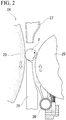
- the centerless grinding process which will be described later can be performed, for example, using a grinding machine 24 as shown in Fig. 2 .
- the grinding machine 24 includes a grindstone 23, an adjustment wheel 25, a work rest 26, and a grinding fluid nozzle 27.
- the outer circumferential surface of the inner ring 3 is subjected to grinding processing by pressing the grindstone 23 against a portion of the outer circumferential surface of the inner ring 3 including the sliding contact surface 10 while rotating the inner ring 3 in one direction.
- the grindstone 23 is a rotary grindstone which has a disk shape, has a generatrix shape along a generatrix shape of the outer circumferential surface of the inner ring 3, and rotates about a central axis (not shown).
- Examples of the grindstone 23 include grindstones formed by bonding A (alumina)-based abrasive grains with a glass-based bond, having a bonding particle size of #60 to #400, a degree of bonding of G to O, a degree of concentration of 4 to 12, and a porosity of 20% to 50%.
- the adjustment wheel 25 can be rotationally driven about the central axis inclined at a prescribed angle with respect to a central axis of the grindstone 23.
- the illustrated grinding machine 24 further includes a cleaning device 28 for removing foreign matters such as grinding debris adhering to an outer circumferential surface of the adjustment wheel 25 during grinding processing.
- the work rest 26 is disposed below a portion between the grindstone 23 and the adjustment wheel 25 and supports the inner ring 3 from below.
- the grinding fluid nozzle 27 is disposed above a portion between the grindstone 23 and the adjustment wheel 25 so that a grinding fluid discharge port is directed downward.
- the inner ring 3 which is a work piece is placed between an upper surface of the work rest 26 and the outer circumferential surface of the adjustment wheel 25. Subsequently, a grinding fluid is discharged toward the outer circumferential surface of the inner ring 3 through the grinding fluid nozzle 27. Moreover, when the grindstone 23 rotating about the central axis of the grindstone 23 itself is pressed against the portion of the outer circumferential surface of the inner ring 3 including the sliding contact surface 10 while rotating the inner ring 3 in one direction (counterclockwise in the illustrated example) by rotatably driving the adjustment wheel 25, the portion is subjected to grinding processing. In this case, when a circumferential speed of the inner ring 3 and a circumferential speed of the grindstone 23 are made different from each other, the inner ring 3 is rotated relative to the grindstone 23 in a prescribed direction (one direction).
- the outer circumferential surface of the inner ring 3 is subjected to grinding processing by pressing a hard grindstone 23 against the outer circumferential surface of the inner ring 3 while rotating the inner ring 3 relative to the grindstone 23 in a prescribed direction. For this reason, deformation such as ridges and burrs is likely to occur on both sides of a portion of the sliding contact surface 10 of the inner ring 3 obtained using centerless grinding process through which abrasive grains of the grindstone 23 has passed.
- the sliding contact surface is subjected to a process for eliminating the directivity of the surface roughness generated on the sliding contact surface 10 using centerless grinding.
- a large number of grinding lines in irregular directions are formed on the sliding contact surface 10 and/or process for improving the surface roughness of the sliding contact surface 10 is performed on the sliding contact surface 10.
- the directionality of the surface roughness is based on a relative moving direction of the sliding contact surface 10 with respect to the grindstone 23 in the centerless grinding.
- an arithmetic average roughness Ra of the sliding contact surface 10 is set to 0.1 ⁇ m or less.
- the finishing step can be performed, for example, as shown in Fig. 3 , using an elastic grindstone 29.
- the elastic grindstone 29 has a disk shape and has a generatrix shape along the generatrix shape of the seal groove 9. Furthermore, the elastic grindstone 29 has more pores and is softer (has appropriate elasticity) than the grindstone 23 used in the centerless grinding process.
- Specific examples of the elastic grindstone 29 include elastic grindstones formed by bonding A (alumina)-based abrasive grains with a resin-based bond, having a bonding particle size of #600 to #1200, a degree of bonding of F to T, a degree of concentration of 6 to 14, and a porosity of 40% to 80%, and softer than the grindstone 23 used in the centerless grinding process.
- the inner ring 3 is rotated about the central axis of the inner ring 3. Moreover, when a surface of a radially outer portion of the elastic grindstone 29 rotated about a central axis of the elastic grindstone 29 itself in the radial direction is pressed against each of the seal grooves 9 of the inner ring 3 and an inner surface of each of the seal grooves 9 including the sliding contact surface 10 is subjected to grinding processing, the surface roughness of the sliding contact surface 10 is improved. That is to say, the unevenness due to the ridges and the burrs formed in the centerless grinding process is reduced.
- the finishing step can be performed using an abrasive grain-containing brush 30 as shown in Fig. 4
- examples of the abrasive grain-containing brush 30 include abrasive grain-containing brushes made of a wire material having appropriate elasticity obtained by mixing nylon fibers such as nylon 6 with A (alumina)-based or GC (green silicon carbide)-based abrasive grains having a particle size of #80 to #600.
- the inner ring 3 is rotated about the central axis of the inner ring 3 while the abrasive grain-containing brush 30 is pressed against each of the seal grooves 9 of the inner ring 3.
- a large number of grinding lines in irregular directions are formed on the sliding contact surface 10 by subjecting the inner surface of each of the seal grooves 9 including the sliding contact surface 10 to polishing processing.
- the finishing step is not limited to the method in which the elastic grindstone 29 or the abrasive grain-containing brush 30 is utilized, the finishing step is not particularly limited as long as a large number of grinding lines in irregular directions are formed on the sliding contact surface 10, and/or the finishing step can improve the surface roughness of the sliding contact surface 10.
- the sliding contact surface 10 is polished by means of a non-woven fabric abrasive obtained by adhering A (alumina)-based or GC (green silicon carbide)-based abrasive grains having a particle size of #80 to #600 to a nylon non-woven fabric, it is possible to form a large number of grinding lines in irregular directions on the sliding contact surface 10.
- the sliding contact surface 10 is polished by means of a polishing tape (a wrapping film) having a surface coated with abrasive grains or the sliding contact surface 10 is subjected to a super-finishing processing in which a reciprocating grindstone is pressed, the surface roughness of the sliding contact surface 10 may be improved.
- the pair of seal grooves 9 can be processed at the same time or the pair of seal grooves 9 can be processed separately (in order).
- the inner ring 3 is completed by subjecting the inner ring track 8 to a super-finishing processing for improving the surface roughness of the inner ring track 8 or, if necessary, performing a heat treatment such as quenching at an appropriate timing.
- the rolling bearing 1 is obtained by combining the inner ring 3 with the outer ring 2, the rolling elements 4, the pair of sealing devices 5, and the retainer 11.
- conventionally known methods can be applied to the method for producing the outer ring 2, the rolling elements 4, the pair of sealing devices 5, and the retainer 11, and the method for assembling the rolling bearing 1.
- the finishing step is performed after the centerless grinding process is performed in this example, a large number of grinding lines in irregular directions can be formed on the sliding contact surface 10 and/or the surface roughness of the sliding contact surface 10 can be improved. Therefore, according to this example, a difference in sliding torque of the distal end portion of the seal lip 20 with respect to the sliding contact surface 10 between the relative rotation of the inner ring 3 with respect to the outer ring 2 in a first direction and the relative rotation thereof in a second direction opposite to the first direction can be kept small as compared with a structure as it is subjected to the centerless grinding processing.
- the surface roughness of the sliding contact surface 10 is improved in the finishing step, that is, when the unevenness of the sliding contact surface 10 is reduced, the relative rotation of the inner ring 3 with respect to the outer ring 2 is less affected by deformation due to ridges and burrs formed in the centerless grinding process on the distal end portion of the seal lip 20.
- the directivity of the surface roughness generated on the sliding contact surface 10 using centerless grinding is eliminated.
- a difference in sliding torque of the distal end portion of the seal lip 20 with respect to the sliding contact surface 10 due to the relative rotation direction of the inner ring 3 with respect to the outer ring 2 can be reduced.
- the rolling bearing in which the directivity of the surface roughness generated on the sliding contact surface 10 is eliminated has high rotational characteristics and is preferably applied to rotating components used under both forward and reverse rotation conditions.
- the method for producing a rolling bearing in this example has, as a target, a rolling bearing (ball bearing) 1 in which balls are used as the rolling elements 4, the method for producing a rolling bearing of the present invention can also have, as a target, a needle bearing, a cylindrical roller bearing, and a tapered roller bearing.
- the present invention is not limited to a single-row rolling bearing, can also have, as a target, a multi-row rolling bearing including multiple rows, and can also have, as a target, a structure in which the distal end portion of the seal lip constituting the sealing device is in contact with the sliding contact surface included in the outer ring in a slidable manner.
- the present invention is not limited to a radial rolling bearing and can also have, as a target, a thrust rolling bearing as long as the thrust rolling bearing includes a sealing device.
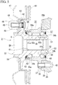
- FIG. 5 A second example of the embodiment of the present invention will be described with reference to Figs. 5 to 9 .
- This example has, as a target, a hub unit bearing which rotatably supports a wheel and a braking rotating body with respect to a suspension device for a vehicle.
- a hub unit bearing 31 rotatably supports a hub 33 which is an inner diameter side track ring member and a rotation side track ring member inside an outer ring 32 which is an outer diameter side track ring member and a fixed side track ring member via a plurality of rolling elements 34a and 34b.
- the outer ring 32 is made of a hard metal such as medium carbon steel and includes a double-row outer ring tracks 35a and 35b and a stationary flange 36.
- the double-row outer ring tracks 35a and 35b are formed on the inner circumferential surface of the axially intermediate portion of the outer ring 32 over the entire circumference.
- the stationary flange 36 is formed to protrude outward in a radial direction of the axial intermediate portion of the outer ring 32 and has support holes 37 which are screw holes at a plurality of places of the radially intermediate portion in a circumferential direction.
- the outer ring 32 is supported and fixed to the knuckle 38 by screwing bolts 40 configured to pass through through holes 39 formed in a knuckle 38 constituting the suspension device of the vehicle into the support holes 37 of the stationary flange 36 from the inside in the axial direction and further tightening the bolts 40.
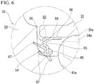
- the inside of the hub unit bearing 31 in the axial direction is referred to as the right side of Figs. 5 and 6 which is a center side of a vehicle body in a state in which the hub unit bearing 31 is assembled to an automobile.
- the outside thereof in the axial direction is referred to as the left side of Figs. 5 and 6 which is an outer side of the vehicle body in a state in which the hub unit bearing 31 is assembled to an automobile.
- Thu hub 33 is disposed coaxially with the outer ring 32 on the inner diameter side of the outer ring 32 and includes a double-row inner ring tracks 41a and 41b and a rotary flange 42.
- the double-row inner ring tracks 41a and 41b are formed on a portion of the outer circumferential surface of the hub 33 facing the double-row outer ring tracks 35a and 35b over the entire circumference.
- the rotary flange 42 is formed to protrude outward in the axial direction at a portion of the hub 33 located further outward in the axial direction than an axially outer end portion of the outer ring 32 and has attachment holes 43 configured to pass through the radially intermediate portion in the axial direction at a plurality of places of the radially intermediate portion in the circumferential direction.
- serration portions formed on portions near a base end of a stud 45 are press-fitted into the attachment holes 43 and an intermediate portion of the stud 45 is press-fitted into through holes 46 formed in the braking rotating body.
- a nut 49 is screwed into a male threaded portion formed on a distal end portion of the stud 45 and further tightened in a state in which the male threaded portion has passed through a through hole 48 formed in the wheel 47.
- an engagement hole 61 configured to engage with a drive shaft (not shown) exists at a central portion of the hub 33.
- the hub 33 is constituted by joining and fixing a hub main body 50 made of a hard metal such as medium carbon steel and having an inner ring track 41a on the outer side in the axial direction and an inner ring 51 made of a hard metal such as bearing steel and having an inner ring track 41b on an inner side in the axial direction to each other.
- a hub main body 50 made of a hard metal such as medium carbon steel and having an inner ring track 41a on the outer side in the axial direction and an inner ring 51 made of a hard metal such as bearing steel and having an inner ring track 41b on an inner side in the axial direction to each other.
- the hub 33 in this example has a sliding contact surface 54 over the entire circumference within a range from the radially inner end portion of the axially inner surface of the rotary flange 42 to a portion of the outer circumferential surface existing further outward in the axial direction than the inner ring track 41a on the outer side in the axial direction.
- the sliding contact surface 54 has a large number of grinding lines formed in irregular directions and/or has an arithmetic average roughness Ra of 0.1 ⁇ m or less.
- the rolling elements 34a and 34b are each made of a hard metal such as bearing steel or ceramics and a plurality of rolling elements 34a and 34b are rotatably disposed between the double-row outer ring tracks 35a and 35b and the double-row inner ring tracks 41a and 41b while being held using retainers 55a and 55b.
- the hub 33 is rotatably supported on the inner diameter side of the outer ring 32.
- balls are used as the rolling elements 34a and 34b.
- an axially inner opening portion of an internal space 56 having the rolling elements 34a and 34b disposed therein is closed by means of a combination seal ring 57 and an axially outer opening portion of the internal space 56 is closed by means of a sealing device 58.
- the combination seal ring 57 is obtained by bring distal end portions of a plurality of seal lips constituting a seal ring 60 which is internally fitted and fixed to the axially inner end portion of the outer ring 32 into contact with a slinger 59 which is externally fitted and fixed to the axially inner end portion of the hub 33 in a slidable manner.
- the sealing device 58 includes an annular core metal 62 and an elastic material 63 made of an elastomer or the like such as rubber reinforced using the core metal 62.
- the core metal 62 has a substantially L-shaped cross sectional shape formed by bending and forming a metal sheet such as mild steel sheet and is constituted to have an annular shape as a whole. That is to say, the core metal 62 includes a fitting cylinder portion 64 which has a cylindrical shape and is internally fitted and fixed to the axially outer end portion of the outer ring 32 and a bent portion 65 which is bent inward in the radial direction from an axially outer end portion of the fitting cylinder portion 64.
- the elastic material 63 includes a base portion 66 and a plurality of (three in the illustrated example) seal lips 67.
- the base portion 66 is fixed to the axially outer surface and the radially inner end portion of the bent portion 65 of the core metal 62 through vulcanization adhesion to cover the axially outer surface and the radially inner end portion.
- Each of the seal lips 67 extends from the base portion 66 toward the sliding contact surface 54 of the hub 33 and has a distal end portion in contact with the sliding contact surface 54 in a slidable manner over the entire circumference.
- an exterior form of the hub main body 50 is formed by subjecting a material made of a metal to forging processing, cutting processing, or the like.
- the outer circumferential surface of the hub main body 50 is subjected to grinding processing by pressing a grindstone 68 against a portion of an outer circumferential surface of the hub main body 50 including the sliding contact surface 54 while the hub main body 50 is rotated relative to a grindstone 68 in a prescribed direction.
- the grindstone 68 in this example is a so-called general type rotary grindstone having a generatrix shape along a generatrix shape of the outer circumferential surface of the hub main body 50 in a range from the sliding contact surface 54 to the axially inner end portion of the cylindrical portion 52.
- the grindstone 68 is, for example, formed by bonding A (alumina)-based abrasive grains with a glass-based bond and can include grindstones having a bonding particle size of #60 to #400, a degree of bonding of G to O, a degree of concentration of 4 to 12, and a porosity of 20% to 50%.
- a magnetic chuck 69 is joined to the axially outer surface of the rotary flange 42 through magnetic attraction.
- the hub main body 50 is rotated.
- the hub main body 50 is positioned in the radial direction by supporting the outer circumferential surface of the intermediate portion of the hub main body 50 in the axial direction using a pair of shoes 70 (only one is shown in Fig. 6 ).
- a generatrix shape of the grindstone 68 is appropriately adjusted using a general type rotary dresser 71 to have a shape along the generatrix shape of the hub main body 50 which has been subjected to the centerless grinding process. Furthermore, deformation such as ridges and burrs is likely to occur on both sides of a portion of the sliding contact surface 54 of the hub main body 50 obtained using centerless grinding process through which the abrasive grains in the grindstone 68 has passed.
- the sliding contact surface 54 is subjected to a process for eliminating the directivity of the surface roughness generated on the sliding contact surface 54 using centerless grinding. For example, a large number of grinding lines in irregular directions are formed on the sliding contact surface 54 and/or a process for improving the surface roughness of the sliding contact surface 54 is performed.
- the sliding contact surface 54 of the hub main body 50 can be subjected to the super-finishing processing.
- the hub main body 50 is rotated by pressing the hub main body 50 in the axial direction using a pressurizing roll 72, pressing the axially outer end portion of the hub main body 50 against a backing plate 73, and rotating the backing plate 73.
- a super-finishing grindstone 76 is pressed against the sliding contact surface 54 by displacing an arm 74 in the axial direction using a feed mechanism 77 while the super-finishing grindstone 76 supported on a distal end portion of the arm 74 is swaged (oscillated) by swaging the arm 74 of a super-finishing board 81 about a swing shaft 75 disposed at a twisted position with respect to a central axis of the hub main body 50.
- the surface roughness of the sliding contact surface 54 is improved by performing the super-finishing processing on the sliding contact surface 54 of the hub main body 50. That is to say, the unevenness due to the deformation such as the ridges and the burrs formed in the centerless grinding process is reduced.
- super-finishing grindstone 76 examples include super-finishing grindstones in which A (alumina)-based or GC (green silicon carbide)-based abrasive grains are bonded with a glass-based bond and which have a bonding particle size of #1000 to #8000 and Rockwell hardness H scale (RH) of -120 to 40.
- A alumina
- GC green silicon carbide
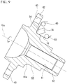
- the finishing step can also be performed using a polishing tape (a wrapping film) 78 having a surface coated with abrasive grains.
- the polishing tape 78 is formed by substantially uniformly applying abrasive grains such as white alumina, green carborundum, and diamond having a bonding particle size of #1000 to #8000 onto a surface of a polyester film having a thickness of 25 ⁇ m to 75 ⁇ m using an adhesive in a thickness range of 5 ⁇ m to 10 ⁇ m.
- the hub main body 50 is rotated about the central axis O 50 of the hub main body 50. Moreover, when the polishing tape 78 is fed from the outer side in the axial direction toward the inner side in the axial direction along the sliding contact surface 54 using a plurality of (only two rolls are shown in Fig. 9 ) rolls 80 while the polishing tape 78 is pressed against the sliding contact surface 54 using the head 79, the sliding contact surface 54 is subjected to tape polishing processing. This improves the surface roughness of the sliding contact surface 54. That is to say, the unevenness due to the ridges and the burrs formed in the centerless grinding process is reduced.
- the finishing step is not limited to super-finishing processing and tape polishing processing.
- Other processing methods in which a large number of grinding lines in irregular directions can be formed on the sliding contact surface 54 and/or the surface roughness of the sliding contact surface 54 can be improved can be adopted.
- the finishing step can be performed by grinding or polishing the sliding contact surface 54 using an elastic grindstone having appropriate elasticity, an abrasive grain-containing brush, or a non-woven fabric abrasive.
- the hub main body 50 is completed by subjecting the inner ring track 41a on the outer side in the axial direction to super-finishing processing and heat treatment such as quenching at an appropriate timing as necessary.
- the hub unit bearing 31 is obtained by combining the hub main body 50 with the outer ring 32, the rolling elements 34a and 34b, the retainers 55a and 55b, the inner ring 51, the combination seal ring 57, and the sealing device 58.
- a conventionally known method can be applied to a method for producing the outer ring 32, the rolling elements 34a and 34b, the retainers 55a and 55b, the inner ring 51, the combination seal ring 57, and the sealing device 58 and a method for assembling the hub unit bearing 31.
- the centerless grinding process is performed and then the finishing step is performed in this example, a large number of grinding lines in irregular directions can be formed on the sliding contact surface 54 and/or the surface roughness of the sliding contact surface 54 can be improved. Therefore, according to this example, the difference in sliding torque of the distal end portion of the seal lip 67 with respect to the sliding contact surface 54 between the relative rotation of the hub 33 with respect to the outer ring 32 in the first direction and the relative rotation thereof in the second direction opposite to the first direction can be kept small.
- the composition and the action effect of other parts are the same as those of the first example of the embodiment.
- the method for producing a hub unit bearing in this example has, as a target, the hub unit bearing 31 using balls as the rolling elements 34a and 34b
- the method for producing a hub unit bearing of the present invention can also have, as a target, the hub unit bearing using the tapered roller as a rolling element.
- the method for producing a hub unit bearing of the present invention is not limited to the hub unit bearing for a drive wheel having engagement holes for engaging the drive shaft in the central portion of the hub and can also have, as a target, the hub unit bearing for a driven wheel whose hub is solid.
- the method for producing a hub unit bearing of the present invention is not limited to the inner ring rotation type hub unit bearing and also has, as a target, the outer ring rotation type hub unit bearing in which the outer diameter side track ring member is used as the rotation side track ring member and the inner diameter side track ring member is used as the fixed side track ring member as long as the hub unit bearing includes a sealing device.
- Fig. 10 is a partial schematic view of a vehicle 200 including a hub unit bearing (a bearing unit) 151.
- the hub unit bearing 151 is for a drive wheel and includes an outer ring 152, a hub 153, and a plurality of rolling elements 156.
- the outer ring 152 is fixed to a knuckle 201 for a suspension device using bolts or the like.
- a wheel (and a braking rotating body) 202 is fixed to a flange (a rotary flange) 153A provided on the hub 153 using bolts or the like.
- the vehicle 200 can have a support structure as in the above description to the hub unit bearing 151 for a driven wheel.
Landscapes
- Engineering & Computer Science (AREA)
- Mechanical Engineering (AREA)
- General Engineering & Computer Science (AREA)
- Manufacturing & Machinery (AREA)
- Rolling Contact Bearings (AREA)
- Sealing With Elastic Sealing Lips (AREA)
- Sealing Of Bearings (AREA)
Applications Claiming Priority (2)
| Application Number | Priority Date | Filing Date | Title |
|---|---|---|---|
| JP2019015850 | 2019-01-31 | ||
| PCT/JP2019/046946 WO2020158161A1 (ja) | 2019-01-31 | 2019-12-02 | 軌道輪部材の製造方法、転がり軸受の製造方法、ハブユニット軸受の製造方法および車両の製造方法 |
Publications (3)
| Publication Number | Publication Date |
|---|---|
| EP3900875A1 true EP3900875A1 (de) | 2021-10-27 |
| EP3900875A4 EP3900875A4 (de) | 2022-03-02 |
| EP3900875B1 EP3900875B1 (de) | 2024-03-20 |
Family
ID=71841324
Family Applications (1)
| Application Number | Title | Priority Date | Filing Date |
|---|---|---|---|
| EP19913321.6A Active EP3900875B1 (de) | 2019-01-31 | 2019-12-02 | Verfahren zur herstellung eines lagerringelements, verfahren zur herstellung eines wälzlagers, verfahren zur herstellung eines nabeneinheitslagers und verfahren zur herstellung eines fahrzeugs |
Country Status (5)
| Country | Link |
|---|---|
| US (1) | US12048984B2 (de) |
| EP (1) | EP3900875B1 (de) |
| JP (1) | JP7140208B2 (de) |
| CN (1) | CN113348052B (de) |
| WO (1) | WO2020158161A1 (de) |
Families Citing this family (2)
| Publication number | Priority date | Publication date | Assignee | Title |
|---|---|---|---|---|
| CN115638182A (zh) * | 2022-11-29 | 2023-01-24 | 八环轴承(长兴)有限公司 | 硅油离合器的双列角接触球轴承、加工设备及加工方法 |
| CN116475862B (zh) * | 2023-05-15 | 2023-09-15 | 山东大众机械制造股份有限公司 | 一种摆动架及加工设备 |
Family Cites Families (15)
| Publication number | Priority date | Publication date | Assignee | Title |
|---|---|---|---|---|
| JPS595253Y2 (ja) * | 1976-12-06 | 1984-02-16 | エヌ・テ−・エヌ東洋ベアリング株式会社 | オイルシ−ルカラ− |
| DE3930059C1 (en) | 1989-09-09 | 1991-02-28 | Herminghausen-Werke Gmbh, 6052 Muehlheim, De | Control for centreless grinding system - involves first bearing in tool slide and second bearing in plate removably fitted to slide |
| JP3772955B2 (ja) * | 1999-11-18 | 2006-05-10 | 日本精工株式会社 | センタレス研削方法 |
| JP2002188646A (ja) * | 2000-12-20 | 2002-07-05 | Nsk Ltd | 転がり軸受及び軸受装置 |
| JP2005299730A (ja) * | 2004-04-07 | 2005-10-27 | Nsk Ltd | 玉軸受軌道輪の製造方法及び密封玉軸受 |
| JP2007187217A (ja) | 2006-01-12 | 2007-07-26 | Ntn Corp | 車輪用軸受装置 |
| JP2007239919A (ja) * | 2006-03-09 | 2007-09-20 | Ntn Corp | 密封型転がり軸受及びその製造方法 |
| JP2011179536A (ja) | 2010-02-26 | 2011-09-15 | Nsk Ltd | センサー付車軸支持用軸受ユニット |
| JP2014126180A (ja) | 2012-12-27 | 2014-07-07 | Minebea Co Ltd | 流量制御バルブ用玉軸受及びこれを組込んだ排出ガス再循環制御バルブ装置 |
| JP6184096B2 (ja) * | 2012-12-27 | 2017-08-23 | ミネベアミツミ株式会社 | 転がり軸受、スロットルバルブ装置及びアンチロックブレーキ装置 |
| JP6523677B2 (ja) * | 2014-12-19 | 2019-06-05 | Ntn株式会社 | 車輪用軸受装置のハブ輪および内方部材の製造方法 |
| WO2017179400A1 (ja) | 2016-04-12 | 2017-10-19 | 日本精工株式会社 | ハブユニット軸受 |
| JP6787198B2 (ja) | 2016-04-12 | 2020-11-18 | 日本精工株式会社 | ハブユニット軸受 |
| JP2018066405A (ja) | 2016-10-18 | 2018-04-26 | 日本精工株式会社 | シールリング付転がり軸受ユニット及びその製造方法 |
| JP2019015850A (ja) | 2017-07-06 | 2019-01-31 | 凸版印刷株式会社 | 印刷用凹版及びその製造方法 |
-
2019
- 2019-12-02 CN CN201980090158.3A patent/CN113348052B/zh active Active
- 2019-12-02 US US17/425,449 patent/US12048984B2/en active Active
- 2019-12-02 JP JP2020561085A patent/JP7140208B2/ja active Active
- 2019-12-02 EP EP19913321.6A patent/EP3900875B1/de active Active
- 2019-12-02 WO PCT/JP2019/046946 patent/WO2020158161A1/ja not_active Ceased
Also Published As
| Publication number | Publication date |
|---|---|
| US12048984B2 (en) | 2024-07-30 |
| CN113348052B (zh) | 2025-02-28 |
| US20220097195A1 (en) | 2022-03-31 |
| EP3900875A4 (de) | 2022-03-02 |
| CN113348052A (zh) | 2021-09-03 |
| JPWO2020158161A1 (ja) | 2021-03-11 |
| JP7140208B2 (ja) | 2022-09-21 |
| WO2020158161A1 (ja) | 2020-08-06 |
| EP3900875B1 (de) | 2024-03-20 |
Similar Documents
| Publication | Publication Date | Title |
|---|---|---|
| JP2001233001A (ja) | 車輪用軸受ユニットとその製造方法 | |
| JPWO2011086982A1 (ja) | 組み合わせシールリング付転がり軸受ユニットおよびその製造方法 | |
| EP3832283B1 (de) | Verfahren und vorrichtung zur inspektion eines laufringelements | |
| US20020066185A1 (en) | Method of machining a hub bearing unit for a wheel of a motor vehicle | |
| EP3900875B1 (de) | Verfahren zur herstellung eines lagerringelements, verfahren zur herstellung eines wälzlagers, verfahren zur herstellung eines nabeneinheitslagers und verfahren zur herstellung eines fahrzeugs | |
| JP2014142054A (ja) | 車輪支持用転がり軸受ユニット | |
| CN101516639B (zh) | 毂轮、毂单元以及加工毂轮的方法 | |
| JP2004092830A (ja) | 車輪用軸受ユニットの製造方法 | |
| US9120195B2 (en) | Wheel assembly and method for making same | |
| JP2018066405A (ja) | シールリング付転がり軸受ユニット及びその製造方法 | |
| US20050231025A1 (en) | Wheel support rolling bearing unit and manufacturing method therefor | |
| JP4064440B1 (ja) | 車輪軸受装置の製造方法 | |
| JP2002347406A (ja) | 車輪用軸受ユニットとその製造方法 | |
| JP2002337502A (ja) | 車輪用軸受ユニットとその製造方法 | |
| JP2002052401A (ja) | 制動用回転体付車輪用軸受ユニットの製造方法 | |
| JP7602316B2 (ja) | 車輪用軸受装置の製造方法及び製造装置 | |
| JP4991233B2 (ja) | 車輪軸受装置における軌道溝の研削方法 | |
| JP2007239919A (ja) | 密封型転がり軸受及びその製造方法 | |
| JP2024047154A (ja) | 車輪支持用円錐ころ軸受ユニットの製造方法 | |
| JP2024136425A (ja) | ハブユニット軸受の製造方法 | |
| JP2003240029A (ja) | 車輪用軸受ユニットとその製造方法 | |
| JP2006021605A (ja) | 車輪支持用転がり軸受ユニット及びその製造方法 | |
| JP2021092239A (ja) | ハブユニット軸受及びその製造方法 | |
| JP2025162765A (ja) | ハブユニット軸受の製造方法 | |
| JP2002323052A (ja) | ころ軸受およびその製造方法 |
Legal Events
| Date | Code | Title | Description |
|---|---|---|---|
| STAA | Information on the status of an ep patent application or granted ep patent |
Free format text: STATUS: THE INTERNATIONAL PUBLICATION HAS BEEN MADE |
|
| PUAI | Public reference made under article 153(3) epc to a published international application that has entered the european phase |
Free format text: ORIGINAL CODE: 0009012 |
|
| STAA | Information on the status of an ep patent application or granted ep patent |
Free format text: STATUS: REQUEST FOR EXAMINATION WAS MADE |
|
| 17P | Request for examination filed |
Effective date: 20210722 |
|
| AK | Designated contracting states |
Kind code of ref document: A1 Designated state(s): AL AT BE BG CH CY CZ DE DK EE ES FI FR GB GR HR HU IE IS IT LI LT LU LV MC MK MT NL NO PL PT RO RS SE SI SK SM TR |
|
| A4 | Supplementary search report drawn up and despatched |
Effective date: 20220202 |
|
| RIC1 | Information provided on ipc code assigned before grant |
Ipc: B60B 27/00 20060101ALI20220127BHEP Ipc: B24B 5/20 20060101ALI20220127BHEP Ipc: B24B 1/00 20060101ALI20220127BHEP Ipc: B24B 5/26 20060101ALI20220127BHEP Ipc: B60B 35/02 20060101ALI20220127BHEP Ipc: B24B 29/00 20060101ALI20220127BHEP Ipc: B24B 21/00 20060101ALI20220127BHEP Ipc: F16C 33/78 20060101ALI20220127BHEP Ipc: F16C 33/64 20060101ALI20220127BHEP Ipc: F16C 19/18 20060101ALI20220127BHEP Ipc: F16C 19/06 20060101ALI20220127BHEP Ipc: B24B 5/18 20060101AFI20220127BHEP |
|
| DAV | Request for validation of the european patent (deleted) | ||
| DAX | Request for extension of the european patent (deleted) | ||
| STAA | Information on the status of an ep patent application or granted ep patent |
Free format text: STATUS: EXAMINATION IS IN PROGRESS |
|
| 17Q | First examination report despatched |
Effective date: 20221017 |
|
| REG | Reference to a national code |
Ref country code: DE Free format text: PREVIOUS MAIN CLASS: B24B0005180000 Ref legal event code: R079 Ref document number: 602019048828 Country of ref document: DE Ipc: B24B0019060000 |
|
| GRAP | Despatch of communication of intention to grant a patent |
Free format text: ORIGINAL CODE: EPIDOSNIGR1 |
|
| STAA | Information on the status of an ep patent application or granted ep patent |
Free format text: STATUS: GRANT OF PATENT IS INTENDED |
|
| INTG | Intention to grant announced |
Effective date: 20231026 |
|
| RIC1 | Information provided on ipc code assigned before grant |
Ipc: F16C 19/18 20060101ALI20231013BHEP Ipc: B24B 1/00 20060101ALI20231013BHEP Ipc: F16C 33/78 20060101ALI20231013BHEP Ipc: F16C 33/64 20060101ALI20231013BHEP Ipc: B24B 5/20 20060101ALI20231013BHEP Ipc: B24B 5/26 20060101ALI20231013BHEP Ipc: B60B 27/00 20060101ALI20231013BHEP Ipc: F16C 33/80 20060101ALI20231013BHEP Ipc: F16C 33/58 20060101ALI20231013BHEP Ipc: B24B 19/06 20060101AFI20231013BHEP |
|
| GRAS | Grant fee paid |
Free format text: ORIGINAL CODE: EPIDOSNIGR3 |
|
| GRAA | (expected) grant |
Free format text: ORIGINAL CODE: 0009210 |
|
| STAA | Information on the status of an ep patent application or granted ep patent |
Free format text: STATUS: THE PATENT HAS BEEN GRANTED |
|
| AK | Designated contracting states |
Kind code of ref document: B1 Designated state(s): AL AT BE BG CH CY CZ DE DK EE ES FI FR GB GR HR HU IE IS IT LI LT LU LV MC MK MT NL NO PL PT RO RS SE SI SK SM TR |
|
| REG | Reference to a national code |
Ref country code: GB Ref legal event code: FG4D |
|
| REG | Reference to a national code |
Ref country code: CH Ref legal event code: EP |
|
| REG | Reference to a national code |
Ref country code: IE Ref legal event code: FG4D |
|
| REG | Reference to a national code |
Ref country code: DE Ref legal event code: R096 Ref document number: 602019048828 Country of ref document: DE |
|
| PG25 | Lapsed in a contracting state [announced via postgrant information from national office to epo] |
Ref country code: LT Free format text: LAPSE BECAUSE OF FAILURE TO SUBMIT A TRANSLATION OF THE DESCRIPTION OR TO PAY THE FEE WITHIN THE PRESCRIBED TIME-LIMIT Effective date: 20240320 |
|
| REG | Reference to a national code |
Ref country code: LT Ref legal event code: MG9D |
|
| PG25 | Lapsed in a contracting state [announced via postgrant information from national office to epo] |
Ref country code: GR Free format text: LAPSE BECAUSE OF FAILURE TO SUBMIT A TRANSLATION OF THE DESCRIPTION OR TO PAY THE FEE WITHIN THE PRESCRIBED TIME-LIMIT Effective date: 20240621 |
|
| PG25 | Lapsed in a contracting state [announced via postgrant information from national office to epo] |
Ref country code: HR Free format text: LAPSE BECAUSE OF FAILURE TO SUBMIT A TRANSLATION OF THE DESCRIPTION OR TO PAY THE FEE WITHIN THE PRESCRIBED TIME-LIMIT Effective date: 20240320 Ref country code: RS Free format text: LAPSE BECAUSE OF FAILURE TO SUBMIT A TRANSLATION OF THE DESCRIPTION OR TO PAY THE FEE WITHIN THE PRESCRIBED TIME-LIMIT Effective date: 20240620 |
|
| REG | Reference to a national code |
Ref country code: NL Ref legal event code: MP Effective date: 20240320 |
|
| PG25 | Lapsed in a contracting state [announced via postgrant information from national office to epo] |
Ref country code: RS Free format text: LAPSE BECAUSE OF FAILURE TO SUBMIT A TRANSLATION OF THE DESCRIPTION OR TO PAY THE FEE WITHIN THE PRESCRIBED TIME-LIMIT Effective date: 20240620 Ref country code: NO Free format text: LAPSE BECAUSE OF FAILURE TO SUBMIT A TRANSLATION OF THE DESCRIPTION OR TO PAY THE FEE WITHIN THE PRESCRIBED TIME-LIMIT Effective date: 20240620 Ref country code: LT Free format text: LAPSE BECAUSE OF FAILURE TO SUBMIT A TRANSLATION OF THE DESCRIPTION OR TO PAY THE FEE WITHIN THE PRESCRIBED TIME-LIMIT Effective date: 20240320 Ref country code: HR Free format text: LAPSE BECAUSE OF FAILURE TO SUBMIT A TRANSLATION OF THE DESCRIPTION OR TO PAY THE FEE WITHIN THE PRESCRIBED TIME-LIMIT Effective date: 20240320 Ref country code: GR Free format text: LAPSE BECAUSE OF FAILURE TO SUBMIT A TRANSLATION OF THE DESCRIPTION OR TO PAY THE FEE WITHIN THE PRESCRIBED TIME-LIMIT Effective date: 20240621 Ref country code: FI Free format text: LAPSE BECAUSE OF FAILURE TO SUBMIT A TRANSLATION OF THE DESCRIPTION OR TO PAY THE FEE WITHIN THE PRESCRIBED TIME-LIMIT Effective date: 20240320 Ref country code: BG Free format text: LAPSE BECAUSE OF FAILURE TO SUBMIT A TRANSLATION OF THE DESCRIPTION OR TO PAY THE FEE WITHIN THE PRESCRIBED TIME-LIMIT Effective date: 20240320 |
|
| REG | Reference to a national code |
Ref country code: AT Ref legal event code: MK05 Ref document number: 1667428 Country of ref document: AT Kind code of ref document: T Effective date: 20240320 |
|
| PG25 | Lapsed in a contracting state [announced via postgrant information from national office to epo] |
Ref country code: SE Free format text: LAPSE BECAUSE OF FAILURE TO SUBMIT A TRANSLATION OF THE DESCRIPTION OR TO PAY THE FEE WITHIN THE PRESCRIBED TIME-LIMIT Effective date: 20240320 Ref country code: LV Free format text: LAPSE BECAUSE OF FAILURE TO SUBMIT A TRANSLATION OF THE DESCRIPTION OR TO PAY THE FEE WITHIN THE PRESCRIBED TIME-LIMIT Effective date: 20240320 |
|
| PG25 | Lapsed in a contracting state [announced via postgrant information from national office to epo] |
Ref country code: NL Free format text: LAPSE BECAUSE OF FAILURE TO SUBMIT A TRANSLATION OF THE DESCRIPTION OR TO PAY THE FEE WITHIN THE PRESCRIBED TIME-LIMIT Effective date: 20240320 |
|
| PG25 | Lapsed in a contracting state [announced via postgrant information from national office to epo] |
Ref country code: NL Free format text: LAPSE BECAUSE OF FAILURE TO SUBMIT A TRANSLATION OF THE DESCRIPTION OR TO PAY THE FEE WITHIN THE PRESCRIBED TIME-LIMIT Effective date: 20240320 |
|
| PG25 | Lapsed in a contracting state [announced via postgrant information from national office to epo] |
Ref country code: IS Free format text: LAPSE BECAUSE OF FAILURE TO SUBMIT A TRANSLATION OF THE DESCRIPTION OR TO PAY THE FEE WITHIN THE PRESCRIBED TIME-LIMIT Effective date: 20240720 |
|
| PG25 | Lapsed in a contracting state [announced via postgrant information from national office to epo] |
Ref country code: SM Free format text: LAPSE BECAUSE OF FAILURE TO SUBMIT A TRANSLATION OF THE DESCRIPTION OR TO PAY THE FEE WITHIN THE PRESCRIBED TIME-LIMIT Effective date: 20240320 Ref country code: PT Free format text: LAPSE BECAUSE OF FAILURE TO SUBMIT A TRANSLATION OF THE DESCRIPTION OR TO PAY THE FEE WITHIN THE PRESCRIBED TIME-LIMIT Effective date: 20240722 |
|
| PG25 | Lapsed in a contracting state [announced via postgrant information from national office to epo] |
Ref country code: ES Free format text: LAPSE BECAUSE OF FAILURE TO SUBMIT A TRANSLATION OF THE DESCRIPTION OR TO PAY THE FEE WITHIN THE PRESCRIBED TIME-LIMIT Effective date: 20240320 |
|
| PG25 | Lapsed in a contracting state [announced via postgrant information from national office to epo] |
Ref country code: EE Free format text: LAPSE BECAUSE OF FAILURE TO SUBMIT A TRANSLATION OF THE DESCRIPTION OR TO PAY THE FEE WITHIN THE PRESCRIBED TIME-LIMIT Effective date: 20240320 Ref country code: CZ Free format text: LAPSE BECAUSE OF FAILURE TO SUBMIT A TRANSLATION OF THE DESCRIPTION OR TO PAY THE FEE WITHIN THE PRESCRIBED TIME-LIMIT Effective date: 20240320 |
|
| PG25 | Lapsed in a contracting state [announced via postgrant information from national office to epo] |
Ref country code: AT Free format text: LAPSE BECAUSE OF FAILURE TO SUBMIT A TRANSLATION OF THE DESCRIPTION OR TO PAY THE FEE WITHIN THE PRESCRIBED TIME-LIMIT Effective date: 20240320 |
|
| PG25 | Lapsed in a contracting state [announced via postgrant information from national office to epo] |
Ref country code: PL Free format text: LAPSE BECAUSE OF FAILURE TO SUBMIT A TRANSLATION OF THE DESCRIPTION OR TO PAY THE FEE WITHIN THE PRESCRIBED TIME-LIMIT Effective date: 20240320 |
|
| PG25 | Lapsed in a contracting state [announced via postgrant information from national office to epo] |
Ref country code: SK Free format text: LAPSE BECAUSE OF FAILURE TO SUBMIT A TRANSLATION OF THE DESCRIPTION OR TO PAY THE FEE WITHIN THE PRESCRIBED TIME-LIMIT Effective date: 20240320 |
|
| PG25 | Lapsed in a contracting state [announced via postgrant information from national office to epo] |
Ref country code: SM Free format text: LAPSE BECAUSE OF FAILURE TO SUBMIT A TRANSLATION OF THE DESCRIPTION OR TO PAY THE FEE WITHIN THE PRESCRIBED TIME-LIMIT Effective date: 20240320 Ref country code: SK Free format text: LAPSE BECAUSE OF FAILURE TO SUBMIT A TRANSLATION OF THE DESCRIPTION OR TO PAY THE FEE WITHIN THE PRESCRIBED TIME-LIMIT Effective date: 20240320 Ref country code: RO Free format text: LAPSE BECAUSE OF FAILURE TO SUBMIT A TRANSLATION OF THE DESCRIPTION OR TO PAY THE FEE WITHIN THE PRESCRIBED TIME-LIMIT Effective date: 20240320 Ref country code: PT Free format text: LAPSE BECAUSE OF FAILURE TO SUBMIT A TRANSLATION OF THE DESCRIPTION OR TO PAY THE FEE WITHIN THE PRESCRIBED TIME-LIMIT Effective date: 20240722 Ref country code: PL Free format text: LAPSE BECAUSE OF FAILURE TO SUBMIT A TRANSLATION OF THE DESCRIPTION OR TO PAY THE FEE WITHIN THE PRESCRIBED TIME-LIMIT Effective date: 20240320 Ref country code: IS Free format text: LAPSE BECAUSE OF FAILURE TO SUBMIT A TRANSLATION OF THE DESCRIPTION OR TO PAY THE FEE WITHIN THE PRESCRIBED TIME-LIMIT Effective date: 20240720 Ref country code: ES Free format text: LAPSE BECAUSE OF FAILURE TO SUBMIT A TRANSLATION OF THE DESCRIPTION OR TO PAY THE FEE WITHIN THE PRESCRIBED TIME-LIMIT Effective date: 20240320 Ref country code: EE Free format text: LAPSE BECAUSE OF FAILURE TO SUBMIT A TRANSLATION OF THE DESCRIPTION OR TO PAY THE FEE WITHIN THE PRESCRIBED TIME-LIMIT Effective date: 20240320 Ref country code: CZ Free format text: LAPSE BECAUSE OF FAILURE TO SUBMIT A TRANSLATION OF THE DESCRIPTION OR TO PAY THE FEE WITHIN THE PRESCRIBED TIME-LIMIT Effective date: 20240320 Ref country code: AT Free format text: LAPSE BECAUSE OF FAILURE TO SUBMIT A TRANSLATION OF THE DESCRIPTION OR TO PAY THE FEE WITHIN THE PRESCRIBED TIME-LIMIT Effective date: 20240320 |
|
| PG25 | Lapsed in a contracting state [announced via postgrant information from national office to epo] |
Ref country code: IT Free format text: LAPSE BECAUSE OF FAILURE TO SUBMIT A TRANSLATION OF THE DESCRIPTION OR TO PAY THE FEE WITHIN THE PRESCRIBED TIME-LIMIT Effective date: 20240320 |
|
| REG | Reference to a national code |
Ref country code: DE Ref legal event code: R097 Ref document number: 602019048828 Country of ref document: DE |
|
| PG25 | Lapsed in a contracting state [announced via postgrant information from national office to epo] |
Ref country code: IT Free format text: LAPSE BECAUSE OF FAILURE TO SUBMIT A TRANSLATION OF THE DESCRIPTION OR TO PAY THE FEE WITHIN THE PRESCRIBED TIME-LIMIT Effective date: 20240320 |
|
| PG25 | Lapsed in a contracting state [announced via postgrant information from national office to epo] |
Ref country code: DK Free format text: LAPSE BECAUSE OF FAILURE TO SUBMIT A TRANSLATION OF THE DESCRIPTION OR TO PAY THE FEE WITHIN THE PRESCRIBED TIME-LIMIT Effective date: 20240320 |
|
| PLBE | No opposition filed within time limit |
Free format text: ORIGINAL CODE: 0009261 |
|
| STAA | Information on the status of an ep patent application or granted ep patent |
Free format text: STATUS: NO OPPOSITION FILED WITHIN TIME LIMIT |
|
| PG25 | Lapsed in a contracting state [announced via postgrant information from national office to epo] |
Ref country code: DK Free format text: LAPSE BECAUSE OF FAILURE TO SUBMIT A TRANSLATION OF THE DESCRIPTION OR TO PAY THE FEE WITHIN THE PRESCRIBED TIME-LIMIT Effective date: 20240320 |
|
| 26N | No opposition filed |
Effective date: 20241223 |
|
| PG25 | Lapsed in a contracting state [announced via postgrant information from national office to epo] |
Ref country code: SI Free format text: LAPSE BECAUSE OF FAILURE TO SUBMIT A TRANSLATION OF THE DESCRIPTION OR TO PAY THE FEE WITHIN THE PRESCRIBED TIME-LIMIT Effective date: 20240320 |
|
| PG25 | Lapsed in a contracting state [announced via postgrant information from national office to epo] |
Ref country code: MC Free format text: LAPSE BECAUSE OF FAILURE TO SUBMIT A TRANSLATION OF THE DESCRIPTION OR TO PAY THE FEE WITHIN THE PRESCRIBED TIME-LIMIT Effective date: 20240320 |
|
| REG | Reference to a national code |
Ref country code: CH Ref legal event code: PL |
|
| PG25 | Lapsed in a contracting state [announced via postgrant information from national office to epo] |
Ref country code: LU Free format text: LAPSE BECAUSE OF NON-PAYMENT OF DUE FEES Effective date: 20241202 |
|
| REG | Reference to a national code |
Ref country code: BE Ref legal event code: MM Effective date: 20241231 |
|
| PG25 | Lapsed in a contracting state [announced via postgrant information from national office to epo] |
Ref country code: BE Free format text: LAPSE BECAUSE OF NON-PAYMENT OF DUE FEES Effective date: 20241231 |
|
| PG25 | Lapsed in a contracting state [announced via postgrant information from national office to epo] |
Ref country code: CH Free format text: LAPSE BECAUSE OF NON-PAYMENT OF DUE FEES Effective date: 20241231 |
|
| PG25 | Lapsed in a contracting state [announced via postgrant information from national office to epo] |
Ref country code: IE Free format text: LAPSE BECAUSE OF NON-PAYMENT OF DUE FEES Effective date: 20241202 |
|
| PGFP | Annual fee paid to national office [announced via postgrant information from national office to epo] |
Ref country code: DE Payment date: 20251028 Year of fee payment: 7 |
|
| PGFP | Annual fee paid to national office [announced via postgrant information from national office to epo] |
Ref country code: GB Payment date: 20251030 Year of fee payment: 7 |
|
| PGFP | Annual fee paid to national office [announced via postgrant information from national office to epo] |
Ref country code: FR Payment date: 20251110 Year of fee payment: 7 |
|
| PG25 | Lapsed in a contracting state [announced via postgrant information from national office to epo] |
Ref country code: CY Free format text: LAPSE BECAUSE OF FAILURE TO SUBMIT A TRANSLATION OF THE DESCRIPTION OR TO PAY THE FEE WITHIN THE PRESCRIBED TIME-LIMIT; INVALID AB INITIO Effective date: 20191202 |