EP3900916A2 - Procédé et dispositif de fabrication générative de composants tridimensionnels - Google Patents
Procédé et dispositif de fabrication générative de composants tridimensionnels Download PDFInfo
- Publication number
- EP3900916A2 EP3900916A2 EP21173236.7A EP21173236A EP3900916A2 EP 3900916 A2 EP3900916 A2 EP 3900916A2 EP 21173236 A EP21173236 A EP 21173236A EP 3900916 A2 EP3900916 A2 EP 3900916A2
- Authority
- EP
- European Patent Office
- Prior art keywords
- substrate plate
- application
- layer
- products
- areas
- Prior art date
- Legal status (The legal status is an assumption and is not a legal conclusion. Google has not performed a legal analysis and makes no representation as to the accuracy of the status listed.)
- Pending
Links
Images


Classifications
-
- B—PERFORMING OPERATIONS; TRANSPORTING
- B29—WORKING OF PLASTICS; WORKING OF SUBSTANCES IN A PLASTIC STATE IN GENERAL
- B29C—SHAPING OR JOINING OF PLASTICS; SHAPING OF MATERIAL IN A PLASTIC STATE, NOT OTHERWISE PROVIDED FOR; AFTER-TREATMENT OF THE SHAPED PRODUCTS, e.g. REPAIRING
- B29C64/00—Additive manufacturing, i.e. manufacturing of three-dimensional [3D] objects by additive deposition, additive agglomeration or additive layering, e.g. by 3D printing, stereolithography or selective laser sintering
- B29C64/20—Apparatus for additive manufacturing; Details thereof or accessories therefor
- B29C64/205—Means for applying layers
-
- A—HUMAN NECESSITIES
- A61—MEDICAL OR VETERINARY SCIENCE; HYGIENE
- A61C—DENTISTRY; APPARATUS OR METHODS FOR ORAL OR DENTAL HYGIENE
- A61C13/00—Dental prostheses; Making same
- A61C13/0003—Making bridge-work, inlays, implants or the like
- A61C13/0006—Production methods
- A61C13/0019—Production methods using three dimensional printing
-
- A—HUMAN NECESSITIES
- A61—MEDICAL OR VETERINARY SCIENCE; HYGIENE
- A61C—DENTISTRY; APPARATUS OR METHODS FOR ORAL OR DENTAL HYGIENE
- A61C13/00—Dental prostheses; Making same
- A61C13/20—Methods or devices for soldering, casting, moulding or melting
-
- B—PERFORMING OPERATIONS; TRANSPORTING
- B29—WORKING OF PLASTICS; WORKING OF SUBSTANCES IN A PLASTIC STATE IN GENERAL
- B29C—SHAPING OR JOINING OF PLASTICS; SHAPING OF MATERIAL IN A PLASTIC STATE, NOT OTHERWISE PROVIDED FOR; AFTER-TREATMENT OF THE SHAPED PRODUCTS, e.g. REPAIRING
- B29C64/00—Additive manufacturing, i.e. manufacturing of three-dimensional [3D] objects by additive deposition, additive agglomeration or additive layering, e.g. by 3D printing, stereolithography or selective laser sintering
- B29C64/10—Processes of additive manufacturing
- B29C64/106—Processes of additive manufacturing using only liquids or viscous materials, e.g. depositing a continuous bead of viscous material
- B29C64/112—Processes of additive manufacturing using only liquids or viscous materials, e.g. depositing a continuous bead of viscous material using individual droplets, e.g. from jetting heads
-
- B—PERFORMING OPERATIONS; TRANSPORTING
- B29—WORKING OF PLASTICS; WORKING OF SUBSTANCES IN A PLASTIC STATE IN GENERAL
- B29C—SHAPING OR JOINING OF PLASTICS; SHAPING OF MATERIAL IN A PLASTIC STATE, NOT OTHERWISE PROVIDED FOR; AFTER-TREATMENT OF THE SHAPED PRODUCTS, e.g. REPAIRING
- B29C64/00—Additive manufacturing, i.e. manufacturing of three-dimensional [3D] objects by additive deposition, additive agglomeration or additive layering, e.g. by 3D printing, stereolithography or selective laser sintering
- B29C64/10—Processes of additive manufacturing
- B29C64/165—Processes of additive manufacturing using a combination of solid and fluid materials, e.g. a powder selectively bound by a liquid binder, catalyst, inhibitor or energy absorber
-
- B—PERFORMING OPERATIONS; TRANSPORTING
- B29—WORKING OF PLASTICS; WORKING OF SUBSTANCES IN A PLASTIC STATE IN GENERAL
- B29C—SHAPING OR JOINING OF PLASTICS; SHAPING OF MATERIAL IN A PLASTIC STATE, NOT OTHERWISE PROVIDED FOR; AFTER-TREATMENT OF THE SHAPED PRODUCTS, e.g. REPAIRING
- B29C64/00—Additive manufacturing, i.e. manufacturing of three-dimensional [3D] objects by additive deposition, additive agglomeration or additive layering, e.g. by 3D printing, stereolithography or selective laser sintering
- B29C64/10—Processes of additive manufacturing
- B29C64/171—Processes of additive manufacturing specially adapted for manufacturing multiple 3D objects
- B29C64/176—Sequentially
-
- B—PERFORMING OPERATIONS; TRANSPORTING
- B29—WORKING OF PLASTICS; WORKING OF SUBSTANCES IN A PLASTIC STATE IN GENERAL
- B29C—SHAPING OR JOINING OF PLASTICS; SHAPING OF MATERIAL IN A PLASTIC STATE, NOT OTHERWISE PROVIDED FOR; AFTER-TREATMENT OF THE SHAPED PRODUCTS, e.g. REPAIRING
- B29C64/00—Additive manufacturing, i.e. manufacturing of three-dimensional [3D] objects by additive deposition, additive agglomeration or additive layering, e.g. by 3D printing, stereolithography or selective laser sintering
- B29C64/20—Apparatus for additive manufacturing; Details thereof or accessories therefor
- B29C64/227—Driving means
- B29C64/236—Driving means for motion in a direction within the plane of a layer
-
- B—PERFORMING OPERATIONS; TRANSPORTING
- B29—WORKING OF PLASTICS; WORKING OF SUBSTANCES IN A PLASTIC STATE IN GENERAL
- B29C—SHAPING OR JOINING OF PLASTICS; SHAPING OF MATERIAL IN A PLASTIC STATE, NOT OTHERWISE PROVIDED FOR; AFTER-TREATMENT OF THE SHAPED PRODUCTS, e.g. REPAIRING
- B29C64/00—Additive manufacturing, i.e. manufacturing of three-dimensional [3D] objects by additive deposition, additive agglomeration or additive layering, e.g. by 3D printing, stereolithography or selective laser sintering
- B29C64/20—Apparatus for additive manufacturing; Details thereof or accessories therefor
- B29C64/245—Platforms or substrates
-
- B—PERFORMING OPERATIONS; TRANSPORTING
- B29—WORKING OF PLASTICS; WORKING OF SUBSTANCES IN A PLASTIC STATE IN GENERAL
- B29C—SHAPING OR JOINING OF PLASTICS; SHAPING OF MATERIAL IN A PLASTIC STATE, NOT OTHERWISE PROVIDED FOR; AFTER-TREATMENT OF THE SHAPED PRODUCTS, e.g. REPAIRING
- B29C64/00—Additive manufacturing, i.e. manufacturing of three-dimensional [3D] objects by additive deposition, additive agglomeration or additive layering, e.g. by 3D printing, stereolithography or selective laser sintering
- B29C64/30—Auxiliary operations or equipment
- B29C64/386—Data acquisition or data processing for additive manufacturing
- B29C64/393—Data acquisition or data processing for additive manufacturing for controlling or regulating additive manufacturing processes
-
- B—PERFORMING OPERATIONS; TRANSPORTING
- B29—WORKING OF PLASTICS; WORKING OF SUBSTANCES IN A PLASTIC STATE IN GENERAL
- B29C—SHAPING OR JOINING OF PLASTICS; SHAPING OF MATERIAL IN A PLASTIC STATE, NOT OTHERWISE PROVIDED FOR; AFTER-TREATMENT OF THE SHAPED PRODUCTS, e.g. REPAIRING
- B29C64/00—Additive manufacturing, i.e. manufacturing of three-dimensional [3D] objects by additive deposition, additive agglomeration or additive layering, e.g. by 3D printing, stereolithography or selective laser sintering
- B29C64/40—Structures for supporting 3D objects during manufacture and intended to be sacrificed after completion thereof
-
- B—PERFORMING OPERATIONS; TRANSPORTING
- B29—WORKING OF PLASTICS; WORKING OF SUBSTANCES IN A PLASTIC STATE IN GENERAL
- B29C—SHAPING OR JOINING OF PLASTICS; SHAPING OF MATERIAL IN A PLASTIC STATE, NOT OTHERWISE PROVIDED FOR; AFTER-TREATMENT OF THE SHAPED PRODUCTS, e.g. REPAIRING
- B29C67/00—Shaping techniques not covered by groups B29C39/00 - B29C65/00, B29C70/00 or B29C73/00
- B29C67/0007—Manufacturing coloured articles not otherwise provided for, e.g. by colour change
-
- B—PERFORMING OPERATIONS; TRANSPORTING
- B33—ADDITIVE MANUFACTURING TECHNOLOGY
- B33Y—ADDITIVE MANUFACTURING, i.e. MANUFACTURING OF THREE-DIMENSIONAL [3D] OBJECTS BY ADDITIVE DEPOSITION, ADDITIVE AGGLOMERATION OR ADDITIVE LAYERING, e.g. BY 3D PRINTING, STEREOLITHOGRAPHY OR SELECTIVE LASER SINTERING
- B33Y10/00—Processes of additive manufacturing
-
- B—PERFORMING OPERATIONS; TRANSPORTING
- B33—ADDITIVE MANUFACTURING TECHNOLOGY
- B33Y—ADDITIVE MANUFACTURING, i.e. MANUFACTURING OF THREE-DIMENSIONAL [3D] OBJECTS BY ADDITIVE DEPOSITION, ADDITIVE AGGLOMERATION OR ADDITIVE LAYERING, e.g. BY 3D PRINTING, STEREOLITHOGRAPHY OR SELECTIVE LASER SINTERING
- B33Y30/00—Apparatus for additive manufacturing; Details thereof or accessories therefor
-
- B—PERFORMING OPERATIONS; TRANSPORTING
- B33—ADDITIVE MANUFACTURING TECHNOLOGY
- B33Y—ADDITIVE MANUFACTURING, i.e. MANUFACTURING OF THREE-DIMENSIONAL [3D] OBJECTS BY ADDITIVE DEPOSITION, ADDITIVE AGGLOMERATION OR ADDITIVE LAYERING, e.g. BY 3D PRINTING, STEREOLITHOGRAPHY OR SELECTIVE LASER SINTERING
- B33Y50/00—Data acquisition or data processing for additive manufacturing
- B33Y50/02—Data acquisition or data processing for additive manufacturing for controlling or regulating additive manufacturing processes
-
- B—PERFORMING OPERATIONS; TRANSPORTING
- B33—ADDITIVE MANUFACTURING TECHNOLOGY
- B33Y—ADDITIVE MANUFACTURING, i.e. MANUFACTURING OF THREE-DIMENSIONAL [3D] OBJECTS BY ADDITIVE DEPOSITION, ADDITIVE AGGLOMERATION OR ADDITIVE LAYERING, e.g. BY 3D PRINTING, STEREOLITHOGRAPHY OR SELECTIVE LASER SINTERING
- B33Y80/00—Products made by additive manufacturing
-
- B—PERFORMING OPERATIONS; TRANSPORTING
- B29—WORKING OF PLASTICS; WORKING OF SUBSTANCES IN A PLASTIC STATE IN GENERAL
- B29C—SHAPING OR JOINING OF PLASTICS; SHAPING OF MATERIAL IN A PLASTIC STATE, NOT OTHERWISE PROVIDED FOR; AFTER-TREATMENT OF THE SHAPED PRODUCTS, e.g. REPAIRING
- B29C64/00—Additive manufacturing, i.e. manufacturing of three-dimensional [3D] objects by additive deposition, additive agglomeration or additive layering, e.g. by 3D printing, stereolithography or selective laser sintering
- B29C64/10—Processes of additive manufacturing
- B29C64/141—Processes of additive manufacturing using only solid materials
- B29C64/153—Processes of additive manufacturing using only solid materials using layers of powder being selectively joined, e.g. by selective laser sintering or melting
-
- B—PERFORMING OPERATIONS; TRANSPORTING
- B29—WORKING OF PLASTICS; WORKING OF SUBSTANCES IN A PLASTIC STATE IN GENERAL
- B29C—SHAPING OR JOINING OF PLASTICS; SHAPING OF MATERIAL IN A PLASTIC STATE, NOT OTHERWISE PROVIDED FOR; AFTER-TREATMENT OF THE SHAPED PRODUCTS, e.g. REPAIRING
- B29C64/00—Additive manufacturing, i.e. manufacturing of three-dimensional [3D] objects by additive deposition, additive agglomeration or additive layering, e.g. by 3D printing, stereolithography or selective laser sintering
- B29C64/10—Processes of additive manufacturing
- B29C64/188—Processes of additive manufacturing involving additional operations performed on the added layers, e.g. smoothing, grinding or thickness control
-
- B—PERFORMING OPERATIONS; TRANSPORTING
- B29—WORKING OF PLASTICS; WORKING OF SUBSTANCES IN A PLASTIC STATE IN GENERAL
- B29L—INDEXING SCHEME ASSOCIATED WITH SUBCLASS B29C, RELATING TO PARTICULAR ARTICLES
- B29L2031/00—Other particular articles
- B29L2031/753—Medical equipment; Accessories therefor
- B29L2031/7532—Artificial members, protheses
- B29L2031/7536—Artificial teeth
Definitions
- the invention relates to a device for the production of products with individual geometry, comprising a substrate plate, a material application device movable relative to the substrate plate for applying material to the substrate plate, preferably above the substrate plate, and a control device which is signal-coupled to the material application device.
- Generative manufacturing processes i.e. manufacturing processes in which a material is shaped into an individual product in an additive manufacturing process, are used in the area of prototyping and are now also used in product manufacture, especially in the manufacture of individually shaped products or small series Application found.
- a generative or additive manufacturing method is to be understood in particular as any additive manufacturing method defined in ASTM F2792-10, including any method of material connection for the production of objects from 3D model data, in particular 3D printing, fused deposition modeling, selective laser sintering or melting and stereo lithography.
- EP 1021997B1 it is known, for example, to produce individually shaped dentures or dental accessories by means of a selective laser sintering process under certain parameters.
- the SLS or SLM process is in principle in EP 0734842 A1 the disclosure of which is fully incorporated in this regard.
- SLS selective laser sintering or laser melting process
- other generative manufacturing processes may also be suitable for other products.
- a high-energy beam such as a laser beam or electron beam
- a plastic in solid or liquid form is passed through a high-energy beam, such as an electron beam, a laser or bundled light beam is selectively cured by photopolymerization
- the material is also applied in layers as a homogeneous layer or as selectively applied areas of a layer and cured, but here the use of a high-energy beam is dispensed with.
- a first material is applied as a layer and then this material is selectively mixed in predetermined areas with a second material and thereby hardened, for example by injecting a liquid binder material in the predetermined areas or by adding a chemically reactive resin to the first and second material + Hardener combination.
- the material is not applied as a homogeneous coherent layer, but rather the material is selectively applied only in predetermined areas of a layer and then cures automatically.
- Such methods encompassed by the invention are known, for example, as 3D printing, contour crafting, fused deposition modeling (FDM), laminated object modeling (LOM), polyamide casting, and as multi-jet modeling.
- a fundamental problem with additive manufacturing processes is the long period of time that passes between the creation of the manufacturing data and the completion of the product. It is known to have several products on a substrate plate at the same time to build up generatively in order to increase the number of products manufactured in a certain period of time. This procedure is particularly useful for products with very small dimensions in relation to the dimensions of the substrate plate and leads to an effective increase in productivity.
- WO 2008/128502 a device is known which follows the same basic idea and provides a conveyor device within the manufacturing device with which one or more construction containers as well as dosing or storage containers can be conveyed in order to achieve simple, fast and safe powder handling within the manufacturing device.
- a conveyor device within the manufacturing device with which one or more construction containers as well as dosing or storage containers can be conveyed in order to achieve simple, fast and safe powder handling within the manufacturing device.
- products can be manufactured in a building container by means of a powder material in a rapid manner and then, after these products have been manufactured in a second building container, products can be manufactured using a different powder material.
- the manufacturing process requires at least as long as the time between the creation of the manufacturing data for all products on the substrate plate and the completion of the products, so that the manufacturing with respect to each of a plurality of products that are assembled continues as takes a relatively long period of time.
- a method for the generative production of three-dimensional objects in layers is known, in which several objects are produced simultaneously in two construction areas.
- a layer is applied in one building area and selective curing is achieved in another building area by means of radiation.
- Four process chambers are provided, which can be in the form of spatially separated individual chambers or as partial areas of two double chambers or one quadruple chamber.
- a laser can be connected to one of the process chambers via a switching device.
- the device described in this way and the method described for the generative production of products with this device have the disadvantage that a separate control of the application process in each of the process chambers is required for the purpose of simultaneous production with alternating curing and layer application in the respective process chambers.
- the manufacturing process and the device are complex both in terms of structure and control and can therefore be more efficient in terms of productivity Manufacturing numerous small products and further optimizing the time that elapses between the completion of the manufacturing data of a product and the completion of the product itself.
- additive manufacturing is made to order in many areas of application with individual product geometries takes place, for example in the manufacture of dentures in dental laboratories.
- the individual orders typically do not arrive at the user of the production device at the same time, but rather at different times.
- the user has to bundle several orders in order to manufacture the products contained in the bundled orders simultaneously on a substrate plate.
- this creates a considerable delay between the receipt of the order and the completion of the product, especially for the order received first.
- the user wants to serve each order in the shortest possible time and manufacture the corresponding individual product, he is forced to carry out the manufacturing process on a substrate plate with only one or a few products, which leads to an overall low utilization of the manufacturing device and low productivity.
- the data required for production i.e. production parameters and geometric data of the geometry of the individual layers / the product geometry
- an external control unit for example a computer connected to the production facility
- production facility can be sent or can be created and / or stored in a control unit in the production facility itself.
- a production process it is also possible for a production process to be controlled and carried out externally by means of cloud computing from several computers that are communicating with one another.
- control device is designed to control the material application device in such a way that it selectively releases the material onto predetermined areas which correspond to the cross section of a product in the respective layer correspond
- material application device is designed to apply the material in a plane which is inclined, in particular at an angle that is less than or equal to the angle of repose of the material, aligned to the surface of the substrate plate to which the material is applied.
- a generative manufacturing device which can generatively manufacture small products in a fast manner with high productivity.
- the device according to the invention is characterized in that the material application device with which the material layers are applied to the substrate plate is designed in such a way that this layer application can be carried out at an angle to the surface of the substrate plate.
- An oblique application is understood to mean that an acute angle can be set between the application plane and the surface of the substrate plate, which can be in particular between zero and ninety degrees inclusive, preferably less than 90 ° and / or greater than 0 ° and in particular one May have a lower limit of 5 °, 10 ° or 30 ° and / or an upper limit of 60 °, 80 ° or 85 °.
- An essential element of the method carried out with the device according to the invention is the curable material, which is applied and then cured.
- the material must be suitable to be used in a layer application at an angle to the surface of the substrate plate, but at the same time achieve a sufficient geometric resolution of the product details.
- a curable material is understood to mean a material which, in a processing state, is suitable for being applied homogeneously or selectively in a thin layer and which is curable.
- the curable material must also be suitable for forming a mechanically loadable connection with a previously applied layer and possibly adjacent layer portions of the currently applied layer. This mechanical connection is often made in the course of the curing process.
- the hardenable material assumes a mechanical-structural function of the component.
- the curable material can be transparent or colored. According to the invention, the curable material is applied alone, as a mixture of two or more materials, simultaneously or successively with a time delay, by means of a material application device.
- This material application device is designed accordingly to obtain the material from a material source and to generate a suitable form of delivery for the material and then one or more materials simultaneously or with a time delay in the form of a jet, powder, in the form of balls, drops, strips, beads or the like.
- the material application device can be arranged on a frame and this frame can be arranged on a surface in such a way that the frame is moved in one, two, three or more axes relative to the surface.
- the surface can be, for example, a table surface on which the frame rests in a rollable manner. The surface then represents the substrate plate.
- the movement between the material application device and the surface can in particular also be carried out by a combination of a movement of the material application device relative to the frame in one or more axes and a movement of the frame to the surface about one or more axes that supplement this.
- hardening can be understood to mean melting and subsequent solidification of a material present in wire, particle or powder form, as well as a molten application of a material with subsequent Solidification. Curing can also take place through chemical reaction of a material with the environment, chemical reaction of two or more material components applied simultaneously or with a time delay, or chemical or physical reaction of a material as a result of radiation exposure, for example as photopolymerization.
- the device according to the invention comprises a radiation source for a high-energy beam and beam guiding means for guiding the beam onto predetermined areas of a material layer applied to the substrate plate.
- generative manufacturing processes such as SLS, SLM, build-up welding, LENS or stereolithographic processes can be carried out.
- the device according to the invention can be further developed in that the substrate plate is divided into a plurality of substrate plate segments and the material application device is designed for the simultaneous application of a material layer to a number of the plurality of substrate plate segments.
- the device according to the invention can be developed even further in that the substrate plate segments are releasably connected to one another or releasably to a base carrier.
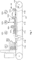
- the substrate plate segments are arranged on an endless conveyor belt, which runs partially or completely in a processing chamber that is sealed against the environment to such an extent that a controlled, in particular inert atmosphere can be set therein and that preferably the material application device so is designed that the material is applied in the first direction, preferably at such an angle to the surface of the respective substrate plate segment that the direction of flow of the material is opposite to the direction of application.
- the device according to the invention can be further developed by a control for controlling the beam guiding means of the high-energy beam and / or the material application device, which is designed to control the beam guiding means and / or the material application device in such a way that a partition wall passes through during the manufacturing process of the product Curing of the applied material or selective application of the material is produced.
- a further preferred embodiment provides that the substrate plate segments and the material application device are movable relative to one another in such a way that the maximum distance between a first substrate plate segment and a material layer applied above this substrate plate segment for the production of the first product differs from the maximum distance between a further substrate plate segment and a for the production of a further product differs from the material layer applied above this further substrate plate segment.
- a material removal device in particular a material suction device, the material removal device being designed to remove uncured material from an area surrounding a manufactured product and being arranged so that it absorbs the material around a finished product removed from a first substrate plate segment, leaving the material around a product on a further, adjacent substrate plate segment.
- the device according to the invention has a control for controlling the guide device of the high-energy beam and / or the material application device, which is designed to control the guide device and / or the material application device in such a way that only layer areas in a first phase of the manufacturing process a layer are selectively cured, which are used to manufacture a first product on a first substrate plate segment, in a final phase of the manufacturing process, only layer areas of a layer are selectively cured, which are used to manufacture a further product on a further substrate plate segment and in one between the first and the middle phase of the production process lying in the last phase, layer areas of a layer are selectively hardened, which are used for the production of the first and the further product.
- the device according to the invention has a partition which is arranged between the substrate plate segments and which separates the installation space above each substrate plate segment from the installation space above an adjacent substrate plate segment.
- the partition between two substrate plate segments is connected to at least one of the two substrate plate segments or is sealed against this substrate plate segment in such a way that no material can pass between the partition and the substrate plate segment.
- the device according to the invention particularly preferably has a single radiation source, which is used in particular by means of a single beam path for curing all products, in particular the products manufactured on all substrate plate segments.
- a control for controlling the guiding device of the high-energy beam and / or the material application device which is designed to guide the high-energy radiation and / or the material application device over the nth material layer according to guiding data derived from the geometric Data of an x-th cross-sectional area of a first product were determined in order to cure parts of the n-th material layer by means of exposure to high-energy radiation or selective application, to guide the high-energy radiation and / or the material application device over an n + 1-th material layer according to guide data , which were determined from the geometric data of an x + 1-th cross-sectional area of the first product, to divide parts of the n + 1-th.
- the relative movement between the substrate plate and the material application device is achieved partially or completely by means of a conveyor device which executes a conveying movement along at least one axis and optionally along two or three axes and can also be designed to be pivotable about one, two or three axes could.
- the conveyor device can in particular comprise one or more conveyor belts which can be controlled simultaneously and independently of one another in order to produce products thereon.
- the conveying device can comprise a receiving device for receiving substrate plates or have a surface which serves directly as a substrate plate surface, for example a conveyor belt surface.
- the plurality of conveyor belts can run next to one another in one plane or can be arranged in such a way that they delimit an installation space at the bottom, at the side and / or at the top, in order to achieve a uniform conveyance of the material.
- the substrate plate and / or an actuator interacting with the substrate plate can be designed to be advanced in a horizontal direction each time a new layer is built up.
- this advance mode achieves the stroke required for the application of a new layer, which in turn determines the layer thickness multiplied by the sine of the application angle.
- the material application device is guided in such a way that it is mounted displaceably in a plane which runs obliquely to the surface of the substrate plate.
- the device according to the invention can be developed by a second material application device, which is designed and movable around a second Apply material as a homogeneous layer before a selective material application takes place.
- the material application device is designed to selectively apply a material mixture of two different materials, the two different materials being designed to cure with one another after the selective application by chemical reaction, or to selectively apply a material, the material being formed are to cure after the selective application by chemical reaction with an ambient gas, or to apply a molten material selectively, wherein the molten material are designed to harden after the selective application by cooling.
- the material application device (s) is / are arranged and designed in relation to the substrate plate and the direction of gravity in the operating position of the device in such a way that the material dispensed therefrom in the direction of gravity as a layer on the substrate plate or layers arranged thereon predetermined areas of the substrate plate or layers arranged thereon can be supplied.
- the device according to the invention can be developed in that a processing device for removing part of the hardened material areas, preferably for surface grinding of the hardened material areas of a previously applied material layer, is arranged on the material application device.
- Another aspect of this embodiment of the invention is a method for manufacturing products with individual geometry, in particular dental prostheses or dental accessories, with the following steps: manufacturing at least one product on or on the surface of a substrate plate by means of selective curing, in particular by means of selective sintering or melting , Application of a curable material in successive layers, selective curing of one or more predetermined areas after each layer application and in this connection of these areas with one or more areas of the one below Layer, wherein the predetermined area (s) is / are predetermined on the basis of a cross-sectional geometry of the product in the respective layer and the material is selectively applied in the predetermined areas of the layer and the successive layers are applied in layer planes which are inclined are aligned with the surface of the substrate plate.
- the device according to the invention also preferably works according to a method for producing products with individual geometry, in particular dental prostheses or dental accessories, with the steps of producing several products on the surface of a substrate plate by means of selective curing, in particular by means of selective sintering or melting, in which the material is in successive layers is applied, after each layer application, one or more predetermined areas of the applied layer are selectively cured, preferably by means of high-energy radiation, and connected to one or more areas of the underlying layer, the predetermined areas being predetermined based on a cross-sectional geometry of the product in the respective layer in which the successive layers are applied in layer planes which are oriented obliquely to the surface of the substrate plate.
- a substrate plate in a classic construction does not necessarily have to be used, that is to say a circular or square or rectangular one-piece substrate plate.
- the substrate plate according to the invention can be provided, for example, as a substrate conveyor belt or as a substrate plate composed of several segments, in which these substrate plate segments are lined up in one direction, for example.
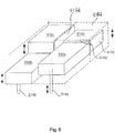
- the method is characterized in that the layers of the curable material are not applied in such a way that the layer plane is aligned parallel to the surface of the substrate plate, but instead are applied in such a way that the layer plane is inclined, ie at an angle between 0 ° and 90 ° is aligned to the surface of the substrate plate.
- This oblique layer application on the substrate plate ensures that the overall material bed thickness therefore arranged at one location on the substrate plate is not the same at every point, but rather different.
- the thickness of the applied material bed increases continuously starting from an area in which exactly one layer thickness rests on the substrate plate up to an area in which the maximum layers that can be applied can be applied above the substrate plate. It should be understood that a material layer is always applied over an area of the substrate plate that does not necessarily have to cover the entire substrate plate, but generally covers an area in which several of the products that are built up on the substrate plate are arranged .
- This manufacturing process makes it possible to start manufacturing a product immediately after completion of the manufacturing data and then to remove this product from the manufacturing process after completion without having to wait for manufacturing data from other products or even other products to have been completed have been completed. It is to be understood that in the same way as a quasi-continuous start of production of successive individual products is realized in the method according to the invention, a quasi-continuous removal of individual finished products can be brought about by the production time for each minimize individual product.
- An oblique material or powder application in relation to the substrate plate makes it possible to manufacture products in different manufacturing stages on a substrate plate and with a common layer application.
- the material or powder is preferably applied along a direction which is opposite to the direction of flow of the powder in the layer due to the force of gravity, if the layer runs obliquely to the horizontal.
- the successive layers are applied parallel to one another.
- the parallel application of the layers enables a constant layer thickness along the entire application process and thus simple process control.
- each of the layers does not necessarily have to have the same thickness; in particular, the layer thickness can be selected larger or smaller depending on the product geometry in order to adapt the geometric resolution of the product geometry given by the layer thickness.
- the substrate plate by means of selective curing, in particular by means of selective sintering, melting or application, and that preferably the one or more predetermined areas are cured or selectively applied by means of high-energy radiation and in this case be connected to one or more areas of the underlying layer.
- each of the successive layers is applied at an angle which is less than or equal to the angle of repose of the material on the substrate plate.
- the angle at which a layer is applied is to be understood as the angle which is included as an acute angle between the plane of the surface of the substrate plate and the plane of the applied layer.
- the angle of repose of the material is to be understood as the angle that is between sets the side surfaces of a mountain of material and a base to which the material is applied by way of a bed.
- the angle of repose of a material is the smaller, the greater the sliding ability of the material on the surface to which it is applied and the higher the sliding ability of the material in itself, for example the sliding ability of the individual powder grains of a powdery material against one another.
- the successive layers in the method according to the invention are applied at an angle that is smaller than the angle of repose or corresponds to the angle of repose, it can be ensured in this way that an applied layer does not slip off layer parts or individual material particles or the like Loses shape afterwards. Instead, when choosing such an application angle, it is ensured that the layer remains stable as a free bed and can consequently be selectively cured in a simple and geometrically precise manner.
- the surface of the substrate plate can be processed in a specific way, for example by polishing, grinding, lapping, honing , Pickling, trovaling, sandblasting, milling, turning and other processing methods such as structuring the substrate plate surface by selective material application of the curable material in the form of a regular or irregular grid structure, point structure, line structure or the like, which is further preferably on a microscopic scale with structure sizes below one Millimeters or a macroscopic scale with structure sizes above one millimeter.
- the substrate plate surface and / or if necessary are examples of the substrate plate surface by selective material application of the curable material in the form of a regular or irregular grid structure, point structure, line structure or the like, which is further preferably on a microscopic scale with structure sizes below one Millimeters or a macroscopic scale with structure sizes above one millimeter.
- a manufacturing device can have a control device for generating such a structuring and / or an application device for applying such a pressure-sensitive adhesive.
- the manufacturing process can preferably be set in such a way that one for one large angle of repose favorable roughness of the substrate plate is achieved, which is typically in the range of 0.5 ⁇ m to 50 ⁇ m Rz (mean surface roughness according to DIN EN ISO 4287: 1998), or typically in the range of 0.1 ⁇ m to 10 ⁇ m Ra (mean roughness) or in the range from 0.04 mm to 1.3 mm Rsm (mean groove width according to DIN EN ISO 4287: 1998 for periodic profiles, such as can be found in milling, for example).
- Rz mean surface roughness according to DIN EN ISO 4287: 1998)
- Ra mean roughness
- Ra mean roughness
- Rsm mean groove width according to DIN EN ISO 4287: 1998 for periodic profiles, such as can be found in milling, for example.
- the surface of the powder can preferably be processed by polishing, grinding, pickling, sandblasting, trovaling or coating in order to positively influence the angle of repose in the above-mentioned sense.
- the wettability of the surface can be positively influenced by a chemical, optical or mechanical surface treatment, such as laser beam roughening.
- Another starting point for positively influencing the angle of repose in the above sense is the aforementioned granulation of the material. This can be done, for example, by pouring molten metal in a thin stream into cold water with constant stirring in order to obtain granulated material.
- Other, easily fusible metals can be granulated by pouring them into a can with a thick layer of chalk on the inside and shaking the can after closing it until the metal has cooled down.
- the material is processed in such a way that a good connection, clamping or the like of the material particles to one another and a correspondingly poor sliding ability of the particles to one another is established, i.e. the particles should in particular have an outer shape deviating from the spherical shape, at the same time a high surface roughness have and in particular preferably continue to be of an overall irregular shape.
- the lubricity of the material also influences its suitability to be applied in thin layers and to be packed tightly with small voids.
- the material must therefore be processed in such a way that, on the one hand, a maximum angle of repose is achieved.
- the substrate plate is moved between two successive layer application processes with a directional component perpendicular to the plane in which the layer is applied.
- a directional component is to be understood as a movement component which, together with other movement components taking place in other directions, makes up the overall movement.
- a movement component perpendicular to the plane of the layer application can generate a feed which enables a subsequent layer application without the layer application device having to be moved in any other way than parallel to the plane of the layer application.
- this directional component can be brought about by moving the substrate plate in a direction parallel to the surface of the substrate plate. Due to the angle between this surface and the plane of the layer application, such a movement contains the directional component required for the feed required for the successive layer application.
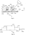
- the surface of the substrate plate in the area in which the layers are applied runs horizontally with respect to the direction of gravity.
- the layer is applied in a plane which runs obliquely to the horizontal and the layer application device must be designed for such a layer application which runs obliquely to the horizontal.
- the surface of the substrate plate in the area in which the layers are applied runs obliquely to the horizontal in relation to the direction of gravity.
- the fact that the surface of the substrate plate runs obliquely to the horizontal in the layer application area enables the layer to be applied in a horizontal plane.
- the layer application device can accordingly be designed for a movement in a horizontal plane. It is to be understood that even if the substrate plate runs obliquely to the horizontal, a material application that also runs obliquely to the horizontal can be carried out and the material application device can be designed accordingly.
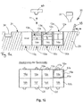
- the applied layers are moved into an adjacent manufacturing section, which lies adjacent to a manufacturing section in which the layers are applied, and is designed as a holding area, in which an upper surface formed by the applied layers of the applied material is covered and supported by a lower surface of a cover plate running parallel to the surface of the substrate plate.
- the material in a certain manufacturing section in which the height of the material above the substrate plate has reached a certain height, the material is supported by the substrate plate on the one hand and a cover plate on the other.
- the distance between the substrate plate and the cover plate corresponds to the maximum height of the layer bed, i.e. the number of layers multiplied by the layer thickness.
- the material can be stabilized in a favorable manner on the substrate plate and, as a result, the oblique layer application can be accomplished in a geometrically precise and reproducible manner.
- the cover plate comes into contact with the end regions of the material layers pointing away from the substrate plate and supports them.
- the cover plate can also be designed in the form of an endless conveyor belt or a plate moving with it, which moves synchronously with the movement of the substrate plate. In this way, a relative movement between the applied material and the cover plate is avoided, which could otherwise result in a disruption of the uniformity of the layer application in the edge area to the cover plate.
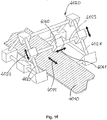
- the surface of the substrate plate is divided into a first surface of a first substrate plate segment and at least one further surface of a further substrate plate segment.
- the substrate plate is divided into two or more adjacent substrate plate segments.
- a substrate plate segment is to be understood as a section of the substrate plate which is separate in terms of manufacturing technology and which can be defined solely on the basis of control data of the layer application and the curing sequence.
- a substrate plate segment represents the area of the substrate plate on which one or more products are manufactured that can be removed from the substrate plate at the same time, since they are started and finished almost at the same time.
- a substrate plate segment can in particular also be understood to mean a physically separate component.
- the substrate plate is composed of several segments that are joined to one another. In this case, the segments can also be used to build one or more products on each segment, which are started and completed at the same time and can then be detached from the substrate plate segment.
- the substrate plate segments are detachably connected to one another or detachably to a base support and each substrate plate segment is detached from an adjacent substrate plate segment or the base support after the production of one or more products on its surface, around the product (s) located thereon (e) to add further processing steps.
- further processing steps can, for example, be careful separation of the product from the substrate plate segment, post-processing by machining, subsequent hardening and the like.
- the substrate plate segments are provided next to one another in the production section in which the layers are applied in such a way that no material can pass between the substrate plate segments.
- the provision made in this way of the substrate plate segments is particularly advantageous if layers are applied over several substrate plate segments in one operation using a single layer application device. In this case, it is prevented that material from a layer application can pass between the substrate plate segments, which on the one hand could have an undesirable loss of material and on the other hand a geometric influence on the layer thickness and the course of the layer. This can be achieved, for example, in that the substrate plate segments with mutually congruent edge sections bear directly against one another or in that a corresponding separate seal is arranged between two substrate plate segments.
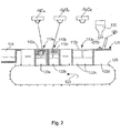
- the substrate plate is designed as an endless conveyor device, in particular in that the substrate plate segments are designed as segments of an endless conveyor device.
- the substrate plate segments can for example be attached to an endless conveyor belt or connected to one another in such a way that they form such an endless conveyor belt in the form of a link chain.
- the substrate plate segments can be moved in succession along an upper run and a lower run, the layer application and the selective layer hardening taking place during the movement along the upper run.
- the removal of non-hardened, applied material from the space between the manufactured products and the removal of the products can also take place in the area of the upper strand, for example by means of appropriate suction devices or mechanical separating devices.
- the substrate plate segments are designed and arranged in such a way that a first product or a group of first products is built up on a single substrate plate segment and that a further product or a Group of further products is built on a further or more further substrate plate segments.
- one or more products can be produced on a single substrate plate segment in order to produce small products in a very fast production time with high productivity.
- a group of several products can be produced on two or more substrate plate segments. This can be necessary in particular for products that extend very far in only one specific direction.
- a product can be produced whose length extends over several substrate bed segments. If several such products are to be produced, a group of such products can be formed according to this form of development and this group can then be produced over several substrate plate segments.
- the method according to the invention is characterized in particular in that the material is applied and selectively cured as a cohesive layer on the first and the at least one further substrate plate segment in such a way that the maximum distance between the first substrate plate segment and a layer section applied to it to produce the first product is Layer in at least one, preferably several, in particular all process stages differs from the maximum distance between the further substrate plate segment and a layer section of the layer applied to it for the production of the further product.
- the material is at least in one process stage of production in such a way that the distance between a first substrate plate area and the layer applied above this area is greater than the distance between another substrate plate area and the layer applied above this other area which is the same layer as before.
- the inventive The method is further developed by the steps: removing material which is arranged on the first substrate plate segment and which has not been cured, without removing material from a further substrate plate segment, and then removing material which is arranged on a further substrate plate segment and which has not been cured.
- the uncured material it is particularly advantageous at the removal point if the uncured material can be removed in such a way that an adjacent area is not affected and the uncured material remains in this adjacent area.
- the uncured material has a support function and is used to absorb and carry overlying layers. The uncured material must therefore usually not be removed before the product has fully built up and cured.
- the material removal device can manage the material removal without affecting the immediately adjacent area. This enables fast and quasi-continuous production and avoids providing a safety distance between the layer application device and the material removal device.
- a partition is provided between the substrate plate segments, which separates the installation space existing above each substrate plate segment from the installation space existing above an adjacent substrate plate segment.
- a partition enables or simplifies the removal of uncured material above a substrate plate segment without influencing the uncured material in a substrate plate segment adjacent thereto.
- a partition can be provided as part of the manufacturing device and in this case, for example, can be designed so that it is tracked simultaneously with the layer application, by the exact height or slightly less than the exact height of the material application in the area to have between two substrate plate segments.
- the partition is produced by curing the applied material material during the production process of the product (s). With this form of training, such a partition is produced from the applied material at the edge of a substrate plate segment during the production process.
- This procedure has the advantage that structurally complex dividing wall tracking can be dispensed with. Instead, a corresponding partition is built along the edge region of a substrate plate segment, which can then also be removed when the products are removed from the substrate plate segment or which is removed from the adjacent substrate plate segment in the course of removing uncured material.
- the partition between two substrate plate segments is connected to at least one of the two substrate plate segments.
- the connection can be made by generative construction of the partition on a or both substrate plate segments or by correspondingly constructive connection of a partition wall component belonging to the device.
- the material is applied to the substrate plate in a quasi-continuous process in a first manufacturing section and that predetermined areas of each applied layer are selectively cured and fully cured products are removed quasi-continuously in a second manufacturing section.
- a quasi-continuous, generative manufacturing process is carried out, which is characterized by high productivity and at the same time can also generatively manufacture very small products in a very short period of time.
- This manufacturing method enables high-quality additive manufacturing in a first manufacturing section and, at the same time, removal of finished products, which does not negatively affect this additive manufacturing, in a second manufacturing section, which is spaced from the first manufacturing section.
- the first manufacturing section can be kept in a closed, inert atmosphere in order to be able to set the boundary conditions required for additive manufacturing according to certain processes, whereas the second manufacturing section enables the products to be diverted or the products already at the transition from the first to the second production stage can be discharged from the inert atmosphere.
- the cured areas of the previously applied layer are ground on the surface before each material application.
- a surface treatment which can take place in particular as grinding, but also by other machining production processes with a geometrically defined or geometrically undefined cutting edge, the geometrical precision of the generative production process is further increased.
- a machining process provides a defined support surface and connection point for the overlying layer and the areas to be hardened therein.
- a defined layer thickness is set by machining, which is advantageous for a reproducible geometric production result.
- a single radiation source in particular a single beam path from a single radiation source, is used for curing the product (s) on the substrate plate, in particular on all substrate plate segments.
- several radiation sources or several beam paths from a single radiation source can also be used to accelerate the production process.
- the manufacturing method according to the invention is, however, particularly characterized in that although it manufactures several products at the same time and these products are in different manufacturing stages, i.e. in particular are made up of a different number of layers.
- a layer can be applied by a single layer application device for all substrate plate segments and the products to be manufactured built on them, and that the specific areas of a layer for all products to be manufactured can also be hardened by a single radiation source .
- the method according to the invention can be further developed by the steps: selective application of a material layer or application of an nth material layer to a substrate carrier plate and selective curing of parts of the material layer by means of the action of high-energy radiation, in particular laser radiation, on these parts of the material layer, guiding the high-energy radiation or a selective material application device over the n-th material layer according to guide data, which were determined from the geometric data of an x-th cross-sectional area of a first product, selective application of a material layer or application of an n + 1-th material layer on the n- th material layer, guiding the high-energy radiation or a selective material application device over the n + 1-th material layer according to guiding data which were determined from the geometric data of an x + 1-th cross-sectional area of the first product, Füh Ren the high-energy radiation or a selective material application device over the nth material layer according to guide data, which were determined from the geometric data of a y-th cross-sectional area of a second product
- a device for manufacturing products with individual geometry comprising a substrate carrier device, a material application device that can be moved relative to the substrate carrier device for applying material, preferably above the substrate carrier device , a control device, which is signal-technically coupled to the material application device, which is further developed by an input interface coupled to the control device signal-technically for selection between a first and a second application mode, wherein it is further provided that the control device and the application device are designed to be used in the first application mode a three-dimensional product on the surface of a substrate plate connected to the substrate carrier device by means of an additive manufacture manufacturing process by applying a curable material in successive layers, one or more predetermined areas are selectively hardened after or with each layer application and here these predetermined areas are connected to one or more areas of the underlying layer, wherein the / the predetermined (s) Areas based on a cross-sectional geometry of the product in the respective
- the invention is directed to a method and a device for additive manufacturing in combination with a method and a device for black-and-white or color printing.
- the device is characterized in that, on the one hand, it carries out a material application in the first mode, in which the material is built up in layers and consequently a connection is established between an applied layer and a previously applied layer.
- the material application device is designed for the application of an application material designed for this purpose.
- a color is applied to a print carrier.
- This color is not necessarily designed to form a connection with one another or to harden, but is characterized by color fidelity and brilliance.
- a color in the sense of this description and the claims is to be understood as a colored material which has a processing consistency so that it can be applied by means of the application device, for example a liquid such as ink from an inkjet printer or toner powder from a laser printer.
- the color is characterized in that it essentially does not form a raised structure on the print carrier, but in particular is partially or completely absorbed by the print carrier in order to achieve a fixation of the print image.
- an additive manufacturing device which, on the one hand, gives the user greater freedom in the aesthetic design of the products manufactured with it, and, on the other hand, allows a more universal mode of use.
- the device is characterized by the fact that, on the one hand, it enables additive manufacturing of three-dimensional products, by building them up in layers. An additive manufacturing process is used for this, which can work according to numerous different manufacturing principles.
- additive manufacturing processes can be used here, in which a homogeneous layer is first applied and then selected areas of this layer are selectively hardened, for example by correspondingly selective application of a further material, which leads to the solidification of the material of the homogeneous layer in the selective area or by exposure to radiation on selective areas with the aim of sintering, melting, photopolymerization of the material of the homogeneous layer in these areas.
- a selective layer application already takes place, ie the material is only applied selectively in predetermined areas of a layer and these selective areas are cured.
- curing is understood to mean the structural solidification of the material in the specified geometric dimensions with simultaneous connection of the selectively hardened areas with adjacent areas of the same layer or with already hardened areas of an adjacent layer.
- the device according to the invention is then particularly characterized in that, in addition to such an additive manufacturing method for a three-dimensional product, the device is also designed to perform conventional printing in two-dimensional form.
- This two-dimensional printing is basically carried out in such a way that a print material is selectively applied to a print carrier, as is known, for example, from printing devices based on the ink jet principle or the laser beam principle by means of a correspondingly selective application of paint by means of a print head or a print roller.
- the device according to the invention can be used for this second mode as Any printing technology can be implemented and in particular designed for black and white printing or color printing by appropriate provision of colored materials, but is characterized, among other things, by the fact that the substrate carrier device is designed and controlled accordingly for executing the first order mode.
- the device according to the invention provides an advantageous combination of two manufacturing processes provided therein, which specifically use jointly used components and thereby enable a compact and cost-effective construction of the device.
- the interaction of the first and second order mode also makes it possible, on the one hand, to print out a three-dimensional view of a product in two-dimensional form from an original data form by means of appropriate data preparation and consequently to provide it, on the other hand, to produce the product shown in the three-dimensional view as a tangible three-dimensional object.
- the device is therefore particularly suitable for the visualization and development of such three-dimensional products and avoids time-consuming transformations and the use of different devices in the development process for such products.
- the device according to the invention comprises a substrate carrier device which serves to be used both in the production of three-dimensional products in the first application mode and in two-dimensional printing in the second application mode.
- the substrate carrier device can in particular be designed to accommodate a substrate plate or a plurality of substrate plates. It can also be designed in such a way that it itself is used as a substrate plate, for example in that the substrate carrier device is designed as a conveying device with a corresponding surface for building three-dimensional products on it.
- the conveyor devices described above in particular the configurations as a conveyor belt.
- the substrate carrier device is also designed to connect a print carrier to it, such a connection being understood to mean that the print carrier is placed on the substrate carrier device, can be fixed thereon or in a form-fitting or force-fitting manner, and in particular the substrate support device is also designed to to obtain print media from a magazine or to convey it out and to move it into the area of the material application device.
- the substrate carrier device itself can be movable in the direction of one or more axes in order to thereby provide the relative movement to the material application device.
- This relative movement can in principle be provided by a stationary one partner (material application device or substrate carrier device) and another partner (material application device or substrate carrier device) that can be moved in a corresponding multi-axis manner, but the invention also includes composite forms of movement in which both partners move in the direction of certain axes and In particular, pivoting about certain axes are also possible in order to achieve the execution of the movements for the first and second order mode.
- the device according to the invention is developed by a print head movable along at least one axis for the selective coating of the predetermined areas with a curable material in the first application mode and for applying paint to the predetermined areas in the second application mode.
- one or more print heads are provided which are each designed to deliver both the material for a three-dimensional print and the ink for a two-dimensional print onto selective areas.
- the pressure head can be moved along at least one axis in order to provide the relative movement that is necessary for the selective application. Basically you can a plurality of such printheads can be present along a common axis or along parallel axes, in order to thereby enable an efficient and fast manufacturing process and printing process.
- an embodiment can also be provided in which at least two print heads are provided and here one of the two print heads is designed for the application of the curable material and the other of the two print heads is designed for the application of paint in the second application mode.
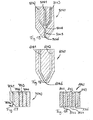
- a first inlet opening opening into a paint duct optionally further inlet openings opening into corresponding further paint ducts for each additional color and a second inlet opening for the hardenable liquid which open into a material duct are provided and that the paint duct (s) and the material line channel open into a common dispensing nozzle, preferably open into a common line channel which opens into a dispensing nozzle, or a first inlet opening opening into a paint line channel, optionally further inlet openings opening into correspondingly further color line channels for each additional color and a second entry opening into a material line channel Inlet opening for the curable liquid are provided and that the paint line channel (s) and the material line channel open into dispensing nozzles that are spaced apart from one another, preferably j Each paint duct opens into dispensing nozzles that are spaced apart from one another.
- the print head or the nozzles / delivery nozzles of the print head can in particular comprise an actuator in order to implement a type of bubble jet printer, piezo printer or pressure valve printer for the delivery of the curable material / color (s).
- the material / the color (s) can be subjected to pressure in order to release them from the print head; this pressure can be generated, for example, in the area of a material or ink tank or in the area of the print head.
- control device and the application device are designed to apply material and one or more colors to an area in a third application mode in one, preferably each layer, in particular by adding material and one or more colors in front of or are mixed in the print head and the mixture is subsequently applied or the material and the color (s) is applied simultaneously or staggered through separate nozzles and the application is carried out in such a way that the material of the layer is applied in a predetermined color pattern or around material and to apply one or more colors to areas spaced apart from one another, in particular by applying material from a first material application nozzle and one or more colors from one or more paint application nozzles and the application is carried out in such a way that the material of a previously applied layer or d The material of the layer is provided with a predetermined color pattern.
- the device with this third application mode in addition to the direct production of three-dimensional products in one-color design in the color specific to the curable application material in the first application mode and the production of two-dimensional prints on a print carrier in the second application mode, individual three-dimensional products can also be produced take place with selective coloring in the third order mode, whereby the three-dimensional color printing of products can be carried out according to the previously described working methods.
- one or more inlet openings opening into material ducts are provided for the delivery of one or more materials for the formation of different material areas in the product or for the reaction hardening of the several materials with one another. This training enables the production of areas with different material properties in one product and the production of products from materials that require two or more components for curing.
- the device according to the invention by a substrate plate magazine and / or a print carrier magazine which mechanically interacts with the substrate plate carrier to supply substrate plates or print carriers from the substrate plate magazine or print carrier magazine to the substrate plate carrier.
- a substrate plate magazine and / or a print carrier magazine which mechanically interacts with the substrate plate carrier to supply substrate plates or print carriers from the substrate plate magazine or print carrier magazine to the substrate plate carrier.
- the print carrier magazine can be designed as a paper magazine in the design known from conventional printers. According to the invention, such a print carrier magazine and a substrate plate magazine can be provided in order to supply the first, second and, if necessary, third order mode with corresponding consumables.
- a substrate plate magazine can also be dispensed with if the substrate carrier device is designed in a corresponding manner and a surface is designed for building up the three-dimensional products and for subsequently separating these products after completion. It is also to be understood that the substrate plates in the substrate plate magazine can be designed as reusable plates that are removed from the device after completion to separate the product built up on it and then, if necessary after appropriate processing, to use it again for the production of a new product.
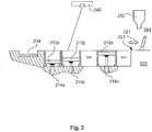
- the device according to the invention can be developed in that the substrate plate carrier is designed as an endless conveyor device and the material application device is designed to dispense the curable material directly onto the substrate plate carrier and / or by arranging a separating device on the substrate plate carrier for separating the material produced thereon Products after their completion from the substrate plate carrier or a substrate plate arranged thereon, wherein the endless conveyor device is preferably deflected at a deflection device and thereby deformed and the products are thereby separated.
- the endless conveyor device is preferably deflected at a deflection device and thereby deformed and the products are thereby separated.
- a separating device is provided, it being understood that this separating device can be designed in the form of a machining device which carries out an actual separating process by machining. Alternatively, the separating device can also be designed in the form of a mechanism that exerts a shearing or bending force or some other force on the connecting plane of the product with the surface on which the product was built in order to separate the product therefrom. In particular, the separating device can be designed as a pulley of a conveyor belt, which causes a deformation of the conveyor belt from a flat plane into a curved plane and thereby detaches a product built on this conveyor belt in the interface between product and conveyor belt.
- the separating device can alternatively be designed as a heated separating element, for example a sword, a wire or the like, the temperature of which is controlled or regulated in such a way that it is above the melting temperature or the evaporation temperature of the cured material.
- the curable material is dispensed from a first nozzle arrangement with at least one nozzle and the paint is dispensed from a second nozzle arrangement with at least one nozzle and that the first and second nozzle arrangement are arranged on a printhead which, during the application is moved along at least one axis, or the first nozzle arrangement is arranged on a first printhead and the second nozzle arrangement is arranged on a second printhead, and the first and / or second printhead is moved along an axis during the job, the axes of the printheads being parallel to one another lie, in particular coaxially, and / or the first and second nozzle arrangements are moved independently of one another during the application.
- each nozzle arrangement can comprise one or more nozzles.
- the nozzle arrangements can be arranged on one and the same print head and consequently be designed to be movable together; in other preferred embodiments the nozzle arrangements are arranged on separate, separate print heads and can consequently be moved independently of one another.
- the mentioned embodiments are suitable for executing the first and second application mode as well as the possibly third application mode for producing a selectively colored, three-dimensional product.
- a nozzle is to be understood as an outlet opening adjoining a channel, the cross section of which can correspond to the channel cross section or can be narrowed in relation to it.
- the substrate carrier device and the material application device are movable relative to one another and are guided on guide devices in such a way that the successive layers in the first application mode are applied in layer planes that are oriented obliquely to the surface of the substrate plate, the color preferably in the second application mode is applied in a layer plane corresponding to the first operating mode, in particular along a layer plane lying in such a layer plane Axis, and the substrate plate or the print carrier is moved during the application process in at least one direction which has a directional component perpendicular to the layer plane.
- a specifically advantageous construction for guiding the relative movement between the material application device and the substrate carrier device is provided, which enables a continuous manufacturing process for three-dimensional products and for two-dimensional prints.
- the device is characterized in that the layer is applied obliquely to the surface of the substrate plate or substrate carrier device or obliquely to the feed movement that the substrate carrier device executes between the application of two layers.
- This inclined arrangement makes it possible on the one hand to manufacture products with a large longitudinal extension in an additive manufacturing process with the device according to the invention; theoretically, a product of infinite length can be manufactured with this configuration of the device.
- the alternative mode of operation is also achieved in the second application mode, in particular in which the application device is moved along an axis in the inclined plane and a movement along a second axis is provided, in particular in that the print carrier is conveyed along this second axis will.
- control device is designed to control the material application device in such a way that it selectively releases the material onto predetermined areas which correspond to the cross section of a product in the respective layer,
- the device according to the invention can be further developed by a control for controlling the material application device, which is designed to control the material application device so that a partition is produced during the manufacturing process of the product by curing the applied material.
- the material application device is guided in such a way that it is mounted displaceably in a plane which runs obliquely to the surface of the substrate plate.
- the device according to the invention can be further developed by a second material application device which is designed and movable in order to apply a second material as a homogeneous layer before a selective material application takes place.
- the material application device is designed to selectively apply a material mixture of two different materials, the two different materials being designed to cure with one another after the selective application by chemical reaction, or to apply a material selectively, the material are designed to cure after the selective application by chemical reaction with an ambient gas, or to apply a molten material selectively, wherein the molten material are designed to harden after the selective application by cooling.
- the material application device (s) is / are arranged and designed in relation to the substrate plate and the direction of gravity in the operating position of the device in such a way that the material dispensed therefrom in the direction of gravity as a layer on the substrate plate or layers or layers arranged thereon. can be fed to predetermined areas of the substrate plate or layers arranged thereon.
- control device is designed to control the material application device and / or the conveying device in such a way that a layer is applied with a thickness between 5 ⁇ m and 200 ⁇ m.
- the device for two-dimensional and three-dimensional printing can also be developed in such a way that the additive manufacturing process takes place in the first order mode and possibly in the third order mode of this type and the device is developed accordingly, as is correspondingly described for the device explained above.
- the object according to the invention is achieved by a method for manufacturing products with individual geometry, in particular dental prostheses or dental accessories, in which an input interface is used to choose between a first or a second application mode and then at least one three-dimensional product in the first application mode is produced on or on the surface of a substrate plate by means of an additive manufacturing process, with the steps of applying a curable material in successive layers, selective curing of one or more predetermined areas after or during each layer application and in doing so connecting these predetermined areas with one or more areas of the underlying ones Layer, wherein the predetermined area (s) is / are predetermined based on a cross-sectional geometry of the product in the respective layer, and the curable material in several superimposed layers taking place is applied for the production of the three-dimensional product, wherein in the second application mode one or more colors are applied to selective areas of a print carrier to create a single or multi-colored print.
- the method can be developed in that the areas to be selectively coated are reached by moving a print head along at least one axis and the print head is designed to dispense a curable material in the first application mode and to dispense one or more colors in the second application mode.
- the method can be developed in that one color enters the print head through a first inlet opening into a color line channel, each additional color enters the print head through a correspondingly further inlet opening into a correspondingly further color line channel and the curable liquid enters the print head through a second inlet opening Material line channel enter, and that the paint line channel / channels and the material line channel open into a common dispensing nozzle, preferably open into a common line channel which opens into a dispensing nozzle, or the one Color enter the printhead through a first inlet opening in a color duct, each additional color enter the printhead through a correspondingly further inlet opening in a corresponding further ink duct and the hardenable liquid enters a material duct through a second inlet opening, and that the first is the ink duct and the Material ducts open into dispensing nozzles that are spaced apart from one another, preferably each paint duct opens into dispensing nozzles that are spaced apart from one another.
- the method can be developed even further by applying material and one or more colors simultaneously to an area in a third application mode in one, preferably each layer, in particular by mixing material and one or more colors in the print head and then applying the mixture is, and the application takes place in such a way that the material of the layer is applied in a predetermined color pattern or material and one or more colors are applied simultaneously to areas spaced apart, in particular by material from a first material application nozzle and one or more colors from a or a plurality of paint application nozzles is applied and the application is carried out in such a way that the material of a previously applied layer or the material of the layer is provided with a predetermined color pattern.
- a plurality of different materials are applied, preferably from several material application nozzles, and that the three-dimensional product hardens through reaction of the different materials with one another or the three-dimensional product has areas with different mechanical material properties.
- the method can be developed in that the substrate plate is conveyed from a substrate plate magazine and / or the print carrier is conveyed from a print carrier magazine.
- the method can be further developed in that the substrate plate is designed as an endless conveyor device and the products manufactured thereon after their completion are separated from the substrate plate by a separating device, in particular by deflecting the substrate plate and thereby deforming it and thereby separating the products.
- the method can be further developed in that the curable material is dispensed from a first nozzle arrangement with at least one nozzle and the paint is dispensed from a second nozzle arrangement with at least one nozzle and that the first and second nozzle arrangements are arranged on a printhead that runs along during the order at least one axis is moved, the first nozzle arrangement is arranged on a first print head and the second nozzle arrangement is arranged on a second print head, and the first and / or second print head is moved along an axis during the order, the axes of the print heads being parallel to one another, in particular coaxially, and / or the first and second nozzle arrangements are moved independently of one another during the application.
- the method can be further developed in that the successive layers are applied in the first application mode in layer planes that are oriented obliquely to the surface of the substrate plate, the color in the second application mode is preferably applied in a layer plane that corresponds to the first operating mode, in particular along an in such a layer plane lying axis, and the substrate plate or the print carrier is moved during the application process in at least one direction which has a directional component perpendicular to the layer plane.
- the method can be further developed in that the additive manufacturing process is developed in the first order mode according to one of the dependent claims 38-50 or 58-67.
- a device for manufacturing products with individual geometry comprising a substrate plate, a material application device for applying material above the substrate plate, wherein the substrate plate is divided into several substrate plate segments that can be detached with one another or with a Basic supports are connected.
- the device according to the invention is characterized in that a material application device is arranged above a substrate plate, with which a material layer can be applied to all substrate plate segments of the substrate plate in one operation and / or a control device coupled with the material application device for signaling is designed to control the material application device in this way that it selectively dispenses the material onto predetermined areas which correspond to the cross-section of a product in the respective layer.
- This can in particular be a material application device which can be moved relative to the substrate plate for applying material to the substrate plate, preferably a material application device arranged above the substrate plate.
- a radiation source can be provided above the substrate plate.
- the material application device and radiation source are controlled by means of a production control device in such a way that the material layer applied in the first operation is either applied selectively in predetermined areas and cures there or, if necessary, in a further operation with the radiation source or some other means, for example by adding another material to predetermined areas the layer, can be selectively cured.
- the substrate plate is divided into several segments.
- the segments can be detachably connected to one another, which is to be understood as meaning that in each case one segment is connected to only one adjacent segment or one Segment can be connected to several surrounding segments.
- the segments are arranged next to one another and each segment is detachably connected to a base support.
- the device according to the invention it is possible in this way to produce several products generatively distributed over several substrate plate segments and to move the substrate plate segments in height relative to one another in such a way that the products are produced in different production stages on the different substrate plate segments and the product or products that have been produced on a first substrate plate segment can be removed with the substrate plate segment and detached therefrom before one or more products are removed from and detached from another substrate plate segment.
- the device can be further developed by a radiation source for a high-energy beam and beam guiding means for guiding the beam onto predetermined areas of a material layer applied to the substrate plate.
- the device according to the invention can be developed in that the material application device is designed for the simultaneous application of a material layer above a number of the plurality of substrate plate segments in one operation.
- the device according to the invention can be developed in that the substrate plate segments and the material supply device can be moved relatively individually to one another by means of one or more actuators in such a way that the distance between the plane of the surface of a first substrate plate segment and a layer area of the material layer applied to it for the production of a first product differs from the distance between the plane of the surface of a further substrate plate segment and a layer region of the same material layer applied to it for the production of the further product.
- the device according to the invention can be developed even further by a material removal device, in particular a material suction device, wherein the material removal device is designed to remove uncured material from an area surrounding a manufactured product, and is arranged so that it can remove the material on a first substrate plate segment while leaving the material on a further, adjacent substrate plate segment.
- a material removal device in particular a material suction device, wherein the material removal device is designed to remove uncured material from an area surrounding a manufactured product, and is arranged so that it can remove the material on a first substrate plate segment while leaving the material on a further, adjacent substrate plate segment.
- the device according to the invention has a control for controlling the guiding device of the high-energy beam or the material application device, which is designed to control the guiding device in such a way that only layer areas of a layer are selectively cured in a first phase of the manufacturing process , which are used to manufacture a first product on a first substrate plate segment, in a last phase of the manufacturing process only layer areas of a layer are selectively cured, which are used to manufacture a further product on a further substrate plate segment and in a middle one between the first and the last phase Phase of the manufacturing process layer areas of a layer are hardened, which are used for the production of the first and the further product.
- the device according to the invention can be further developed by a control for controlling the material application device and / or for controlling at least one actuator for the relative movement between the substrate plate segments and the material application device, which is designed to adjust the height of the material bed after application of all material layers on a first substrate plate segment to provide different from the height of the material bed resulting after application of all material layers on another substrate plate segment.
- a control for controlling the material application device and / or for controlling at least one actuator for the relative movement between the substrate plate segments and the material application device which is designed to adjust the height of the material bed after application of all material layers on a first substrate plate segment to provide different from the height of the material bed resulting after application of all material layers on another substrate plate segment.
- a processing device for removing a surface portion of the hardened Material areas, preferably for surface grinding, the cured material areas of a previously applied material layer is arranged.
- the substrate plate segments are arranged on an endless conveyor belt which runs partially or completely in a processing chamber that is sealed against the environment to such an extent that a controlled, in particular inert atmosphere can be set therein.
- the device can be further developed by at least one lifting device which is or can be coupled to each substrate plate segment in order to raise and lower the respective substrate plate segment in a vertical direction independently of the other substrate plate segments.
- the device according to the invention can be developed even further by a single radiation source which, in particular by means of a single beam path, is used to cure the products produced on all substrate plate segments.
- the device according to the invention can be developed even further by a partition wall arranged between the substrate plate segments, which separates the installation space existing above each substrate plate segment from the installation space existing above an adjacent substrate plate segment.
- the partition between two substrate plate segments is connected to at least one of the two substrate plate segments or is sealed against this substrate plate segment in such a way that no material can pass between the partition and the substrate plate segment.
- the device is characterized by a control for controlling the material application device or the guiding device of the high-energy beam, which is formed is to control the material application device or the guide device in such a way that the partition is produced during the production process of the product by selective application or selective curing of the applied material.
- the device according to the invention can be further developed by controlling the guide device of the high-energy beam and / or the material application device, which is designed to guide the high-energy radiation and / or the material application device over the nth material layer according to guide data, which are derived from the geometric data an x-th cross-sectional area of a first product were determined in order to cure parts of the n-th material layer by means of the action of high-energy radiation or selective application, to guide the high-energy radiation and / or the material application device over an n + 1-th material layer according to guide data, which were determined from the geometrical data of an x + 1-th cross-sectional area of the first product in order to reduce parts of the n + 1-th.
- the device according to the invention preferably works according to a method with the following steps: providing a substrate plate which is subdivided into a first substrate plate segment and at least one further substrate plate segment, which are detachably connected to one another or to a base carrier, production of a first product on the first substrate plate segment by successive application of Layers of material on the first substrate plate segment and selective curing of predetermined areas of each applied material layer after their application, production of at least one further product on the at least one further substrate plate segment by successive application of material layers on the further substrate plate segment and selective curing of predetermined areas of each applied material layer after their application.
- the method proceeds with the following steps: Production of one or more products on or on the surface of a substrate plate by means of selective curing, in particular by means of selective sintering or melting, in which the material is applied in successive layers, after each layer application one or more predetermined areas are selectively cured and connected to one or more areas of the adjacent, in particular the underlying layer, the predetermined areas being predetermined on the basis of a cross-sectional geometry of the product in the respective layer, selective application of the material in the predetermined areas of the layer, and providing a substrate plate which is subdivided into a first substrate plate segment and at least one further substrate plate segment which are detachably connected to one another or to a base carrier, producing a first product a uf or on the first substrate plate segment by successive selective application of predetermined areas of material layers to the first substrate plate segment and selective curing of these predetermined areas of each applied material layer after their application and gfs.
- Manufacture of at least one further product on the at least one further substrate plate segment by successive selective application of predetermined areas of material layers to the further substrate plate segment and selective curing of the predetermined areas of each applied material layer after their application.
- the selective curing takes place after the application and is limited to predetermined areas in that a selective application is carried out.
- the method is characterized in that a substrate plate is provided on which a first and a further product in a first and a corresponding to further substrate plate segments can be produced generatively at the same time and these substrate plate segments are detachably connected to one another or to a base carrier. This makes it possible to remove an individual substrate plate segment after the product built on it has been completed, in order to be able to detach the product from the substrate plate segment, while a further product continues to be produced generatively on another substrate plate segment.
- the material layers can be applied to the at least two substrate plate segments in such a way that at least one of the material layers extends over both substrate plate segments.
- the method can proceed in such a way that a material layer is first applied to the at least two substrate plate segments and this material layer is selectively cured in the area above both substrate plate segments.
- the substrate plate segments can in particular interact with a single coating device in such a way that a product is built up on a substrate plate segment in a first manufacturing stage, for example with an nth layer above the substrate plate and another product is built up on another substrate plate segment in a different manufacturing stage, for example with an m-th built-up layer above the substrate plate, where m is not equal to n and the n-th and m-th layers are applied in one operation by the coating device.
- the method With the method, several products can thus be produced on a substrate plate with production start times staggered in time, the products being partly produced simultaneously and also being detached from the substrate plate with a time delay.
- the production start time can only be after the completion of all production data for all products to be produced on the substrate plate.
- the production start time can be determined individually for each substrate plate segment and, accordingly, an individual production end time can also be achieved for each substrate plate segment.
- the substrate plate can be divided into two, three or more substrate plate segments. This subdivision is to be understood in particular as an actual physical subdivision into individual components which can be put together accordingly to form a substrate plate. In principle, layers can be applied to all substrate plate segments with a single, common layer application device, which is preferred because of the efficient production associated therewith.
- the one or more predetermined areas are selectively cured by means of high-energy radiation and connected to one or more areas of the underlying layer.
- This curing effect can be provided in addition to another curing effect or can act as the sole curing mechanism.
- curing by means of high-energy radiation is to be understood as a process in which a previously liquid material cures through the action of radiation, for example through photopolymerization, or in which a material previously present as a flowable powder, granulate or the like is heated by the action of radiation and thereby is partially or completely melted and then solidified or sintered by cooling.
- this hardening goes with a connection of the material area which is exposed to the action of radiation with a adjacent or underlying material area in order to build up the product as an integral component.
- the substrate plate segments are provided next to one another in such a way that no material can pass through between the substrate plate segments.
- a corresponding seal can be provided between the individual substrate plate segments or the substrate plate segments can be fitted to one another in such a way that a passage of material between the substrate plate segments is not possible.
- the substrate plate segments are designed as segments of an endless conveyor device.
- the substrate plate segments can for example be attached to an endless conveyor belt or connected to one another in such a way that they form such an endless conveyor belt in the form of a link chain.
- the substrate plate segments can be moved in succession along an upper run and a lower run, the layer application and the selective layer hardening taking place during the movement along the upper run.
- the removal of non-hardened, applied material from the space between the manufactured products and the removal of the products can also take place in the area of the upper strand, for example by means of appropriate suction devices or mechanical separating devices.
- the substrate plate segments are designed and arranged in such a way that the first product or a group of first products is built up on a single substrate plate segment and the further product or a group of further products on one or more products several further substrate plate segments is built up.
- one or more products can be produced on a single substrate plate segment in order to produce small products in a very fast production time with high productivity.
- a group of several products can be produced on two or more substrate plate segments. This can be necessary in particular for products that extend very far in only one specific direction.
- a product can be produced whose length extends over several substrate bed segments. If several such products are to be produced, a group of such products can be formed according to this form of development and this group can then be produced over several substrate plate segments.
- the material is applied to the substrate plate in a quasi-continuous process in a first manufacturing section and that predetermined areas of each applied layer are selectively cured and that fully cured products are removed quasi-continuously in a second manufacturing section.
- This manufacturing method enables high-quality additive manufacturing in a first manufacturing section and, at the same time, removal of finished products, which does not negatively affect this additive manufacturing, in a second manufacturing section, which is spaced from the first manufacturing section.
- the first manufacturing section can be kept in a closed, controlled, in particular, inert atmosphere in order to set the boundary conditions required for additive manufacturing according to certain methods whereas in the second production section the products are discharged, or the second production section contains a lock or the products are discharged from the controlled atmosphere during the transition from the first to the second production section.
- a material layer is applied above at least two, preferably several, substrate plate segments
- the material layer is selectively cured, and that the maximum distance between the first substrate plate segment and one for producing the first product thereon applied layer in at least one, preferably several, in particular all process stages differs from the maximum distance between the further substrate plate segment and a layer applied thereon for the production of the further product.
- a process stage comprises the sequence of layer application and selective curing and is consequently carried out repeatedly, whereby successive process stages arise in each process stage a first and second process step is carried out one after the other and here on at least two, in particular several or a material layer is applied to all substrate plate segments in one operation and this is subsequently selectively cured in order to produce several products generatively on the corresponding several substrate plate segments.
- the layer is applied to the substrate plate segments in such a way that the distance between the applied layer and the substrate plate segments is different for at least two, in particular for each substrate plate segment. It should be understood that this maximum distance is different during the layer application and also or only during the selective curing.
- This distance can differ in only one of several successive process stages, each consisting of the sequence of a layer application and the selective curing of this layer, but in particular the distance can differ in all process stages, that is typically that the sum of the applied layers above one Substrate plate segment is different from the sum of the applied Layers above another substrate plate segment, for example because the joint application to the two substrate plate segments was only started at a point in time when one or more layers had already been applied to one of the two substrate plate segments.
- the method can be implemented, for example, in such a way that the substrate plate segments can be moved individually with regard to their height in order to achieve in this way that although a layer is applied to all substrate plate segments in a common plane, the distance between this layer and the Substrate plate segments is different for each substrate plate segment, or by the layer application device is adjusted vertically between the substrate plate segments during the application process.
- the method by the steps of removing material arranged on the first substrate plate segment which has not been cured without removing material from a further substrate plate segment, and subsequent removal of the material arranged on the further substrate plate segment which has not cured became.
- the uncured material can be removed in such a way that an adjacent area is not affected and the uncured material remains in this adjacent area.
- the uncured material has a supporting function and is used to absorb and support the layers above it. The uncured material must therefore usually not be removed before the product has fully built up and cured.
- the material removal device can accomplish the material removal without the immediately adjacent substrate plate segment to influence this. This enables fast and quasi-continuous production and avoids providing a safety distance between the layer application device and the material removal device.
- a first phase of the manufacturing process only layer areas of a layer are selectively hardened which are used to manufacture the first product and in a final phase of the manufacturing process only layer areas of a layer are selectively hardened which are used to manufacture the further product and layer areas of a layer, which are used for the production of the first and the further product, are hardened preferably in a middle phase of the production process between the first and the last phase.
- a partition is provided between the substrate plate segments, which separates the installation space existing above each substrate plate segment from the installation space existing above an adjacent substrate plate segment.
- a partition enables or simplifies the removal of uncured material above a substrate plate segment without influencing the uncured material in a substrate plate segment adjacent thereto.
- a partition can be provided as part of the manufacturing device and in this case, for example, can be designed so that it is tracked simultaneously with the layer application in order to have an exact height or a little less than this exact height that the corresponds to the upper layer surface of the material application in the area between two substrate plate segments.
- the partition is produced by curing the applied material during the production process of the product.
- each time at the edge of a substrate plate segment Such a partition is made from the applied material during the manufacturing process.
- This procedure has the advantage that structurally complex dividing wall tracking can be dispensed with. Instead, a corresponding partition wall is built up along the edge area of a substrate plate segment, which accordingly grows higher with each layer application and in this way is adjusted to the total height of the material layer bed. The partition can then be removed when the products are removed from the substrate plate segment or in the course of the removal of uncured material from the adjacent substrate plate segment.
- the two aforementioned embodiments can be developed further in that the partition between two substrate plate segments is connected to at least one of the two substrate plate segments.
- the partition By connecting the partition to the two substrate plate segments, which separate them from one another, a secure seal against the passage of material between the substrate plate segments can also be achieved at the same time.
- the connection can be achieved here by generative construction of the partition wall on one or both substrate plate segments or by a corresponding structural connection of a partition wall component belonging to the device.
- each substrate plate segment is moved individually with respect to the layer application device in such a way that the distance perpendicular to the surface of the substrate plate and the layer applied with a layer application device is changed and the resulting height of the material bed on a substrate plate segment is different from that Is the height of the bed of material on another segment of the substrate plate.
- each substrate plate segment can be moved individually in height, for example by means of an actuator that acts alternately on the substrate plate segments or by means of several actuators, each of which is provided for a respective substrate plate segment. This means that the substrate plate segments can be placed at different heights in order to then subsequently apply a layer of material in a plane above the substrate plate segments.
- This material layer then lies at an individually different distance from the respective substrate plate segments, i.e. in particular at an individual distance from the plane of the surface of the substrate plate segments on which the first material layer has been applied to the respective substrate plate segment.
- the embodiment is suitable for generatively producing a product in a first process stage on a first substrate plate segment and another product in a different production stage on another substrate plate segment with a common layer application on the two substrate plate segments and can be applied to a corresponding number of substrate plate segments with a corresponding number of products in different process stages be applied.
- the cured areas of the previously applied layer are ground on the surface before each material application.
- a surface treatment which can take place in particular as grinding, but also by other machining production processes with a geometrically defined or geometrically undefined cutting edge, the geometrical precision of the generative production process is further increased.
- a machining process provides a defined support surface and connection point for the overlying layer and the areas to be hardened therein.
- a defined layer thickness is set by machining, which is advantageous for a reproducible geometric production result.
- a single radiation source in particular a single beam path from a single radiation source or a single material application device, is used for curing the first and the at least one further product, in particular all further products.
- several radiation sources or several beam paths from a single radiation source can also be used to accelerate the production process.
- the production method according to the invention is, however, particularly characterized in that it produces several products at the same time and these products in different production stages are, that is to say in particular made up of a different number of layers.
- a layer can be applied by a single layer application device for all substrate plate segments and the products to be manufactured built on them, and that the specific areas of a layer for all products to be manufactured can also be hardened by a single radiation source .
- each substrate plate segment is raised and lowered in a vertical direction by means of a lifting device during the manufacturing process and the raising and lowering movement of the substrate plate segments is independent of one another.
- the independent lifting and lowering movement can in particular be brought about by an actuator acting on a plurality of substrate plate segments in each case, or by an actuator in each case which is assigned to a substrate plate segment in each case.
- the method can be developed through the following steps: selective application of a material layer or application of an nth material layer to a substrate carrier plate and selective curing of parts of the material layer by means of the action of high-energy radiation, in particular laser radiation, on these parts of the material layer, guiding the high-energy Radiation or a selective material application device over the n-th material layer according to guide data, which were determined from the geometric data of an x-th cross-sectional area of a first product, selective application of a material layer or application of an n + 1-th material layer to the n-th material layer Guiding the high-energy radiation or a selective material application device over the n + 1-th material layer according to guide data, which are derived from the geometric data of an x + 1-th cross-sectional area of the first product were determined, guiding the high-energy radiation or a selective material application device over the nth material layer according to guide data, which were determined from the geometric data of a yth cross-sectional area of a second product, and guiding the
- the device according to the invention and the method according to the invention according to the aspects explained in this description are advantageously suitable for various uses.
- the device / method can be used to produce personalized products for a consumer application, for example the device / method can be delivered with a controller that enables the personal creation of figures, play elements and the like.
- the method according to the invention / the device according to the invention can also be used to produce individualized jewelry.
- Another application for the device / method according to the invention is in the production of circuit boards for printed circuits, in particular in a mode of use in which, in addition to the circuit board carrier, conductor tracks arranged thereon are also produced and this through corresponding additive manufacturing with the different required for this purpose Materials is achieved.
- two different materials or materials can also be processed simultaneously or at different times in order to produce a product which is composed of two or more different materials.
- the invention has been further developed to the effect that a first curable material is used to build up layers in a first process step and a second, different from the first, hardenable material is used to build up layers in the same or a subsequent layer in a second process step.
- a first curable material is used to build up layers in a first process step
- a second, different from the first, hardenable material is used to build up layers in the same or a subsequent layer in a second process step.
- the devices / methods according to the invention are in the production of individually shaped foods in smaller or larger series.
- the invention is suitable for the production of food from meat products, from dough material for baked goods, from vegetable or fruit products or confectionery, such as chocolate, which are suitable for processing as a hardenable material and which give the user a creative, in terms of surface / volume Relationships open up advantageous shaping for further processing and taste effect.
- the device according to the invention is / is according to the invention
- the method can advantageously be used to produce gauges, templates, guide devices and the like in an individual manner in such a way that they allow surgical interventions in the course of an operative treatment in a safe manner and with greater precision than previously known procedures with standardized templates / guide devices.
- an advantageous use of the device / method according to the invention lies in the production of individual models for the visualization of products, structural situations in a true-to-scale, reduced or enlarged representation or as a real 1: 1 prototype model, for example in the field of urban planning or architecture.
- FIG Figure 1A shows a receiving device 20 for a total of eight slide-in units 10a-h, which are arranged in two rows and four columns, as shown in FIG Figure 1B can be seen.
- Each insert 10a-h has an individually height-adjustable substrate plate segment 12a-f.
- Each substrate plate segment 12a-f is individually adjustable in height in a vertical direction 11 within its insert 10a-f.
- the vertical direction 11 is here for each of the substrate plate segments 12a-f parallel to one another and perpendicular to the upper surface 13a-f of the substrate plate segments 12a-f, which is oriented horizontally, ie perpendicular to the direction of gravity.
- the evaluations within the receiving device 20 are designed to each receive an insert 10a-f in which a substrate plate segment 12a-f is arranged. It is to be understood, however, that substrate plate segments can also be inserted into the receiving device 20 which are larger Have the base area of the substrate plate 12a, for example a base area that is twice as large or four times as large as that in FIG Fig. 1a, b substrate plate segments shown and occupy two or four slots accordingly.
- a filling block 12g, 12h is inserted in the inserts 10g and 10h, which does not represent a substrate plate segment and is not used for the manufacture of products.
- Each substrate plate segment 12a-f can be adjusted in height by means of an actuator 14a-f, which can be, for example, a linear actuator operated by an electric motor.
- the actuator 14a-f is part of the insert 10a-f.
- Each slide-in unit 10a-f is surrounded by an upwardly open, in cross-section rectangular, in particular square housing which comprises four walls, as shown by way of example on the slide-in unit 10a through the walls 15a-18a.
- the substrate plate segment 12a moves within these walls and seals at its lateral edge area with the walls in such a way that coating material which is applied to the substrate plate segment cannot pass between the substrate plate segment and the walls.
- the upper end edges of the walls are flush with a surface 21 of the receiving device 20 when the inserts 10a-e are inserted into the receiving device.
- an upper surface of the slide-in units 10g, h is aligned with the surface 21 of the receiving device 20.
- a powder application device 30 which comprises a powder conveyor 32 from which powder can be discharged onto the surface 21 of the receiving device, and which further comprises a slide 33 which extends reciprocally along a movement direction 31 over the surface 21 and the substrate plate segments 12a-f or inserts 10a-h can move.
- the slide 33 distributes the powder discharged by the powder conveyor 32 and applies a layer of powder above the substrate plate segments 12a-f.
- the powder application device further comprises a collecting device 34 for excess powder.
- the pusher 33 pushes that powder into the collecting device 34 which could not be applied as a powder layer above the substrate plate segments.
- the substrate plate segments 12a-f are set to different heights by means of their actuators 14a-f, ie the distance between the upper surface 13a-f of each substrate plate segment and the plane of the surface 21 along which the slide 33 moves and, as a squeegee, the Applying powder is different.
- the layer applied during this powder application process is cured above each substrate plate segment 12a-f by means of a radiation source, here a high-power laser 40 in predetermined areas.
- a radiation source here a high-power laser 40
- This selective curing takes place on the basis of control data that correspond to the cross-section of a product in the applied layer.
- the hardened areas are connected at the same time with corresponding areas of the product below that have been hardened beforehand.
- the curing process can take place in particular as selective laser sintering or selective laser melting.
- the beam of the high-power laser 40 is directed with beam steering means in such a way that it strikes the predetermined areas of the previously applied layer and these areas selectively harden above all previously coated substrate plate segments.
- the beam steering means are coupled with a control device for signaling purposes.
- Production data for at least the products to be produced at the same time are stored in the control device.
- the production data include in particular position data which characterize the position of a respective product on the substrate plate and geometry data which the geometry characterize the respective product.
- the geometry data is prepared in such a way that it contains the geometrical data of individual cross-sections of the product.
- the respective position of such a cross section and the geometry data stored for this cross section correspond to the position of the respectively applied material layer from which this product cross section is produced and the geometry of the product in this material layer. In the embodiment shown with products standing vertically on the plate, the geometric data therefore correspond to horizontal cross-sectional planes through this product.
- the slide 33 moves from the left position to the in Figure 1A shown right position back.
- the surface of the selectively hardened areas is ground by means of a grinding device which is arranged on the slide in order to achieve a defined surface for the subsequent coating and curing process and a higher geometric precision of the generatively manufactured component.
- the substrate plate segments 12a-f are lowered by a predefined distance which corresponds to the layer thickness of the subsequently applied layer.
- the surface of the previously applied layer and the areas selectively cured therein are no longer in alignment with the surface 21 along which the slide 33 moves with a lower squeegee edge, but below by the distance by which the substrate plate segment was lowered the plane of this surface 21.
- a metered amount of powder is again dispensed from the powder conveyor 32 onto the surface 21 and, by moving the slide 33 to the left, this powder is applied as a layer above each lowered substrate plate segment.
- this insert can be removed from the receiving device 20 and replaced by a new insert whose substrate plate is in the uppermost position.
- the products in the removed slot can be detached from the substrate plate after the uncured powder material has been removed.
- New products can be manufactured simultaneously on the newly established segment. The time-shifted but at the same time simultaneous construction of products in the device makes it possible to achieve high productivity in the additive manufacturing of products.
- Fig. 2 shows a second embodiment of the invention, in which a plurality of substrate plate segments 112a-c can be coupled as modules 110a-c on an endless conveyor belt 120.
- the actuator within each module is designed to individually adjust the height of the substrate plate segments 112a-c.
- the substrate plate segments 112a and 112b are designed as individual segments, whereas the substrate plate segment 112c is designed as a double segment and extends over twice the length along the conveyor belt 120.
- Each module 110a-c is in turn, like the plug-in units according to FIG Figure 1A , B, provided with side walls within which the substrate plate segments 112a-c can move vertically in a manner sealed at the edges.
- the upper edges of the marginal walls are flush with a surface 121, onto which powder can in turn be dispensed from a powder conveyor 132.
- the surface 121 lies horizontally, ie perpendicular to the direction of gravity and by moving a slide 133 with a lower squeegee edge, which rests on the surface 121, in one direction 131 the powder applied is distributed over the substrate plate segments 112a-c and finally out after moving the slide the in Fig. 2 Excess powder is pushed into a collecting container 134 in the right position shown in a left position horizontally offset to the left for this purpose.
- the production progress in the modules 110a-c increases starting from the right in the conveying direction of the conveyor belt 120 to the left, as shown by the arrow 123.
- the conveyor belt is moved so far that this module can be removed or the module is removed and the conveyor belt is moved forward by the corresponding length of the module.
- a new module can be inserted on the right-hand side adjacent to the position of the slide 133 shown and additive manufacturing can be started in this new module.
- the removed module can be further processed in a further production section
- the non-hardened powder material can be removed therefrom and the products manufactured therein can be removed from the substrate plate segment.
- the particular advantage here is that in the finished substrate plate segment, which was previously subjected to simultaneous production with the other substrate plate segments, it is now possible to remove the uncured powder and the finished products without removing the powder from other substrate plate segments has to be or the manufacturing process has to be stopped in the other substrate plate segments.
- FIG. 3 shows a further embodiment of the invention.
- a plurality of substrate plate segments 212a-c are arranged next to one another and are each surrounded by side walls in a manner that is sealed off from the edge regions of each substrate plate segment.
- the upper edges of the side walls end flush with a surface 221, along which a slide 233 of a powder application device moves with its lower edge, which serves as a squeegee edge, in a direction 231.
- the pusher 233 applies a layer of powder above the substrate plate segments 212a-c in one working stroke and pushes excess powder into a collecting trough 234.
- a laser beam source 240 is also provided, which serves to selectively harden predetermined areas of the applied powder layer above each substrate plate segment.
- a control for the production device is provided, which is designed in such a way that, after each layer application process, predetermined areas above each substrate plate segment are cured by means of the laser beam source 240, as described above.
- a respective actuator 214a-c which serves to individually adjust the height of the substrate plate segments 212a-c and thereby individually change the distance of the upper surface of the respective substrate plate segment from the plane in which the squeegee edge of the slide 133 moves, not part of a Module which is used in a receiving device.
- these actuators are 214a-c integrated in the receiving device 220 and the substrate plate segments 212a-c can be detachably coupled to the actuators 214a-c.
- a quasi-continuous production of products by means of a generative production process such as SLS (Selective Laser Sintering) or SLM (Selective Laser Melting) can take place in the same way, with products being produced simultaneously in several substrate plate segments, which are in a different production stage for each substrate plate segment are.
- This is achieved in that the height of the substrate plate segments can be adjusted individually, which means that a powder bed is applied above each substrate plate segment, the height of which is different between adjacent substrate plate segments, although the respective new layers of the hardenable material are made in a single operation by means of a single slide 133 is applied to the plurality of substrate plate segments 212a-c.
- Fig. 4 shows a fourth embodiment of the invention, which is characterized by certain features.
- the embodiment shown is based on the principle basically similar to that in FIGS Figures 1A - 3 shown embodiments and has a substrate plate segment 312a, which can be arranged adjacent to other substrate plate segments (not shown) and can be individually adjusted in height. It should be understood that this is for Fig. 4
- the principle explained below is based on the Figures 1A - 3 illustrated embodiments can be applied.
- Fig. 4 shows a first metering module 310a, which serves as a metering platform and is filled with powder before the start of a manufacturing process.
- a height-adjustable base plate 312a is moved into the lowest position within the dosing module.
- a radiator field 380 which preheats the powder filled into the dosing module 310a, is arranged above the dosing module 310a.
- a doctor blade 333 is horizontally displaceable along a direction 331.
- a heating band 335 is arranged in front of the doctor blade 333 in the direction of movement and continuously heats the powder moved by the doctor blade or keeps it at the preheated temperature.
- the substrate plate segment 312b is arranged in a building module 310b adjacent to the dosing module 310a.
- the substrate plate segment 312b is individually and independently of the base plate 312a vertically displaceable in the building module 310a.
- the construction module 310b lies with respect to the direction of movement 331 of the squeegee 333 between the metering module 310a and a collecting module 310c, which serves to receive excess powder which has been pushed over the construction module 310b by the squeegee 333.
- a collecting module 310c Also arranged in the collecting module 310c is a base plate 312c which can be displaced vertically individually and independently of the base plate 312a and the substrate plate segment 312b.
- the embodiment shown can also have a plurality of such building modules substrate plate segments. These multiple building modules would be arranged next to one another in the direction of application 313 and the majority of the substrate plate segments would be placed overall between a metering module 310a arranged at one end with respect to the displacement path 331 of the doctor blade 333 and a collecting module 310c arranged at the other end.
- a radiator field 380c is also arranged above the collecting module 310c and serves to keep the excess material collected in the collecting module at a desired temperature.
- a heater 315b is built into the substrate plate segment 312b, which keeps the substrate plate segment and the powder bed arranged thereon at a desired temperature.
- Fig. 4 The embodiment shown is optimized overall in such a way that a desired, preheated powder state of the powder is achieved before the selective curing process in that the radiator fields 380a, b, the heating band 335 and the heater 315b are provided.
- the manufacturing process that can be achieved in the illustrated embodiment consists of a sequence in which the substrate plate segment 312b is first lowered by a certain amount, which corresponds to the layer thickness to be applied, and the platform 312a of the dosing module 315a is raised by a certain amount, which is derived from the cross-section of the platform and calculated according to the powder volume required for the subsequent application process.
- the preheated powder volume is pushed out of the area of the dosing module by horizontal movement of the squeegee 333 over the substrate plate segment 312b and a layer is applied to the substrate plate segment 312b or possibly further substrate plate segments. Excess powder is placed in the collection module.
- the powder layer is selectively hardened in predetermined areas by means of a laser 340 and the areas hardened in the process are connected to previously hardened areas in the layer below.
- the squeegee 333 then moves back, using a grinding device, which is arranged in the direction of movement from left to right in front of the squeegee, the surface of the previously hardened areas are sanded in order to improve the geometrical accuracy of the generatively manufactured product and the connection the subsequent areas to be cured.
- a grinding device which is arranged in the direction of movement from left to right in front of the squeegee, the surface of the previously hardened areas are sanded in order to improve the geometrical accuracy of the generatively manufactured product and the connection the subsequent areas to be cured.
- the process begins again and is repeated until the substrate plate segment arranged above the substrate plate segment 312b or any other in a row of substrate plate segments is closed creating product is finished.
- the laser beam of the laser beam source 340 is selectively guided over each layer in such a way that previously calculated areas of this layer, which correspond to the cross section of the products to be manufactured in the respective layer on all substrate plate segments, are selectively cured.
- the product After completion of the manufacturing process, the product can be separated from the substrate plate segment. It is to be understood in principle that several products can also be produced above a substrate plate segment and that several substrate plate segments can also be coated next to one another in different production stages with the single doctor blade 333 and selectively cured with the single laser 340.
- the powder collected in the collecting module 310c can be lifted by raising the platform 312c and conveyed back into the metering unit from left to right by moving the doctor blade 333 accordingly, in order to start a new production process and use the powder again.
- the function of the dosing module and collecting module can now also be swapped in the subsequent production process, so that the layer application process now takes place by moving the squeegee from left to right and the grinding process by a correspondingly reversed movement from right to left.
- the movable unit consisting of the heating band, doctor blade and grinding device is to be designed to be adjustable accordingly, preferably by 180 ° about a vertical axis.
- FIG. 5 Figure 3 shows a further embodiment of the invention.
- the manufacturing arrangement shown comprises a process chamber 1000 which has a first lock 1010 and a second lock 1020.
- Substrate plate segments are fed through the first lock 1010 and placed on a conveyor belt 1030.
- the substrate plate segments are temporarily stored on this conveyor belt and can be preheated if necessary.
- the substatplate segments can be placed on a building platform 420b of a building block 410b in order to be generatively thereon Manufacture products.
- the plug-in unit 410b is, as before with regard to the embodiment according to FIG Fig. 4 explained with regard to the three modules 312a-c shown there, flanked by a dosing insert 410a and a collecting insert 410c and it is to be understood that several substrate plate segments can also be arranged next to one another between the dosing insert and the collecting insert in order to achieve a quasi-continuous production in the previously explained Way to perform.
- the substrate plate segment 412b can be moved into a lower position. In this lower position, the installation space above the substrate plate segment 412b is connected to a powder suction channel 490 which is let into the wall, which delimits the installation space as a side wall. The non-hardened powder can then be sucked off from the area above the substrate plate segment 412b via this powder suction channel 490.
- the powder suction channel 490 is at the same time designed in such a way that the powder pushed into the collecting insert can also be suctioned off through the suction channel 490, it being understood that this may or may not be provided as an optional further function.
- the construction platform can be moved vertically to the topmost position and the substrate plate segment 412b can again be gripped by means of the robot arm 1040 and fed to a second conveyor belt 1050.
- the substrate plate segment 412b together with the products arranged thereon is conveyed through a tempering furnace 1060 in order to subject the products located thereon to a tempering process and thereby to produce the desired component properties. After tempering has taken place the substrate plate segment 412b can be discharged from the process chamber 1000 through the lock 1020.
- Fig. 6 shows a further aspect of the device according to the invention or the method according to the invention.
- Fig. 6 four substrate plate segments 512a-d arranged in two rows and two columns.
- each of the substrate plate segments is individually adjustable in height by means of a respective lifting / lowering device 514a-d.
- Both the substrate plate segments of a row and the substrate plate segments of a column are vertically displaceable independently of one another, so that products can be produced generatively in different manufacturing stages on each of the substrate plate segments.
- Partition walls are to be provided between the respective substrate plate segments for the purpose of the individual construction of a powder bed above the respective substrate plate segment.
- these partition walls are not part of the device, but that the partition walls are continuously built up by selective curing of the powder material in the edge area of the respective substrate plate segments and consequently grow vertically with the generatively manufactured product in the middle area of the substrate plate segment.
- partition walls are provided as part of the production device and are arranged in such a way that their upper edge is flush with a plane in which a powder applicator blade moves.
- Fig. 7 shows a seventh embodiment of the invention.
- the embodiment has an endless conveyor belt 620, along which a plurality of substrate plate segments 612a-e are arranged in the conveying direction 621.
- the substrate plate segments 612a-e are placed such that their upper surface lies in a common plane.
- a plurality of coating devices 630a-d are arranged above the substrate plate segments 612a-e.
- the individual coating devices 630a-d each include a doctor blade 633a-d.
- the lower edge of the doctor blade 633a is arranged at the distance of one layer from the surface of the substrate plate segments 612a-e.
- the lower edge of the squeegee 633b is, compared to the preceding squeegee 633a, spaced one layer more from the surface of the substrate plate segments 612a-e, and in the same way the lower edges of the squeegee 633c, d are correspondingly one layer thickness more from the surface of the substrate plate segments compared to the previous, neighboring doctor blade raised.
- Fig. 7 The illustrated embodiment is to be understood to mean that a plurality of individual coating devices a, b, c, d ... arranged side by side are provided in such a vertically staggered height arrangement.
- each two layer application devices 633a, b, c... There is an area in which the applied layer can be selectively cured by means of a laser 640a, b, c, d.
- a corresponding laser is assigned to each individual coating device.
- the conveyor belt 620 is moved continuously or discontinuously during production in such a way that the upper run is in the in Fig. 7 shown constellation moved from right to left. As a result, above the substrate plate segments 612a, b, c. In a correspondingly identical manner, the overall height of the products produced generatively on the respective substrate plate segments increases.
- the conveyor belt 620 can also be reciprocally moved back and forth several times during a manufacturing process and the several powder application devices or the conveyor belt can be shifted vertically in order to apply a number of M x N powder layers during a manufacturing process by means of a number of N powder application devices, where M corresponds to the number of reciprocal movements of the conveyor belt.
- the N powder application devices are raised or the conveyor belt is lowered by an amount that corresponds to the N-fold layer thickness in order to achieve that the furthest to the right and consequently the most
- the deepest lying powder application device applies its layer to the layer previously applied by the powder application device located furthest to the left and consequently the highest.
- the non-hardened powder material 590 is suctioned off in the conveying direction to the left of the conveyor belt 520 from the area above a substrate plate segment on which the finished products are built. It should be understood that such a powder suction only takes place above the leftmost substrate plate segment, whereas the substrate plate segment on the right is not yet suctioned off due to the products that are generally not yet finished there. This can be achieved by separating walls constructed in parallel between the substrate plate segments.
- the products produced on the substrate plate segment can be separated from it. If necessary, after this separation process the surfaces of the substrate plate segment can be prepared flat again by means of a device for surface smoothing arranged to the left of the suction, in particular a milling or grinding station or a device for laser smoothing, in order to then feed the substrate plate segment to another generative production.
- a device for surface smoothing arranged to the left of the suction, in particular a milling or grinding station or a device for laser smoothing, in order to then feed the substrate plate segment to another generative production.
- the plurality of radiation sources can be provided by individual laser sources in each case or by one or more laser sources, the beam of which can be divided and consequently directed to a corresponding number of locations. It should also be understood that the split beam and the multiple beam paths generated therefrom can also be guided individually over the respective layers by appropriate radiation guide means in order to cure each layer individually and selectively.
- the layer application process for all substrate plate segments takes place in a common first work step, followed by a selective curing process in a second work step. With a corresponding number of individual coating devices, this can take place with continuous movement of the conveyor belt or - with reciprocal movement of the conveyor belt - in a quasi-continuous process.
- Fig. 8 a further embodiment of the invention can be found.
- several substrate plate segments 712a, b are arranged one above the other and the installation space above the respective substrate plate segments is limited by common side walls 715-718.
- the substrate plate segments 712a, b ... move in a vertical direction of movement from top to bottom through the installation space delimited by the side walls.
- layers are iteratively applied to the construction space provided above the topmost substrate plate segment 712b and selectively cured by means of a laser beam source.
- the layer application process can be carried out in the same way as explained above by means of a doctor blade. This squeegee moves with the in Fig. 8
- a new substrate plate segment can be placed on it, each being coupled in a corresponding manner to a conveyor device for vertical movement.
- the substrate plate segments with finished products built on them can be removed in a manufacturing section arranged below the layer application device and the installation space in which generative production is carried out, in that the powder is sucked off and the products are separated from the substrate plate segment.
- a duct suction can be used in particular, as it is with regard to Fig. 5 has been explained in order to subsequently convey the products into an area that is not limited by side walls and thereby enable the products or the entire substrate plate segment to be removed from the vertical conveying device.
- Fig. 9 shows a substrate plate 2010, which consists of a plurality of substrate plate segments 10a-c.
- the substrate plate segments 2010a-c are detachably connected to a substrate plate carrier 2020 arranged below.
- the substrate plate carrier 2020 and the substrate plate segments 2010a-c are arranged in such a way that the surface of the substrate plate segments 2010a-c are oriented horizontally, ie perpendicular to the direction of gravity, in the operating state of the device.
- a coating device 2030 is arranged in the direction of gravity above the upper support surface of the substrate plate segments 2010a-c.
- the coating device 2030 can be displaced along a movement direction 2031.
- the direction of movement 2031 is straight and forms an angle ⁇ with the plane defined by the upper support surface of the substrate plate segments 2010a-c.
- a heater can be built into each substrate plate segment 2010a-c, which keeps the substrate plate segment and the powder bed arranged thereon at a desired temperature.
- This, and one or more optionally additionally provided radiator fields and / or heating bands in the area of the coating device, which heat the applied powder layer or maintain its temperature, the device can be optimized so that a desired, preheated powder state of the powder is achieved before the selective curing process will.
- the substrate plate segments 2010a-c can be moved continuously or in a clocked, quasi-continuous manner in a direction of movement 2011 which is parallel to the horizontal.
- a direction of movement 2011 which is parallel to the horizontal.
- a radiation source 2040 which is a high-power laser, is arranged in such a way that its beam strikes the surface of an applied layer approximately perpendicularly, preferably precisely perpendicularly.
- the beam from the radiation source 2040 can be directed with beam directing means in such a way that it strikes predetermined areas of an applied layer and selectively hardens them.
- the beam steering means are signal-coupled to a control device.
- Production data for at least the products to be produced at the same time are stored in the control device.
- the production data include in particular position data which characterize the position of a respective product on the substrate plate and geometry data which characterize the geometry of the respective product.
- the geometry data is prepared in such a way that it contains the geometrical data of individual cross-sections of the product.
- the respective position of such a cross section and the geometry data stored for this cross section corresponds to the position of the respectively applied material layer from which this product cross section is produced and the geometry of the product in this material layer. In the embodiment shown with products standing vertically on the plate, the geometric data therefore correspond to inclined cross-sectional planes through this product.
- a powder bed is applied above the substrate plate segment 2010c, which is composed of several layers of powder and which has the maximum height h above the substrate plate segments.
- This maximum height has also already been reached in an area on the left above the substrate plate segment 2010b, but in an area on the right, contrary to the direction of funding 2011 has not yet been fully reached. Instead, the surface of the powder bed runs in this right area of the substrate plate segment 2010b, as well as in a left area of the substrate plate segment 2010c inclined at the angle ⁇ 1.
- a generatively manufactured product 2060b is arranged in a powder bed in cured form.
- a product 2060c is generatively produced above the substrate plate segment 2010a.
- This manufacturing process takes place in that, after each powder layer 1051 has been applied, predetermined areas of this powder layer are selectively cured by means of the radiation source 2040. Subsequently, by advancing the substrate plate segments in the conveying direction 2011, a distance corresponding to the layer height is produced between the plane of the coating device 2030 and the previously applied layer Grinding device can be arranged, which is arranged either in the direction of movement during powder application in front of the position at which the powder is applied, and serves and is designed so that the previously cured areas are ground on the surface.
- the geometrical accuracy of the additively manufactured product can be improved and the connection of the subsequent areas to be cured can be increased.
- Fig. 10 shows a possible structure of a production arrangement and a corresponding process sequence.
- the substrate plate segments 2010a, b, c the in Fig. 9
- the manufacturing section shown is arranged and takes place with respect to Fig. 1 explained manufacturing process instead. After the corresponding generative production of the products in the process chamber 3010, they pass through further movement along the direction of movement 2011 in an exit lock 3020 and are thereby discharged from the process chamber.
- an atmosphere favorable for additive manufacturing in particular an inert gas atmosphere or an active gas atmosphere, can be maintained in the process chamber 3010 and thereby the product quality can be ensured.
- Fig. 11 shows a second embodiment of a manufacturing section for additive manufacturing and a manufacturing section for separating and removing additively manufactured products.
- a plurality of substrate plate segments 2010a, b, c... are arranged next to one another in such a way that a contiguous substrate plate is thereby provided.
- the upper surface of this substrate plate provided by the substrate plate segments 2010a, b, c... Is inclined at an angle ⁇ to the horizontal, ie this surface is at an angle 90 ° - ⁇ to the direction of gravity.
- a coating device 2130 is arranged above the substrate plate segments 2010a, b, c. By means of the coating device In this way, a powder layer from a powder reservoir, which can be arranged on the coating device 2130 or which can be arranged along the movement path 2131 of the coating device 2130, is applied 2130.
- a powder layer can be applied above the substrate plate segments 2010a, b, c ... which is at an angle ⁇ to the upper surface of the substrate plate segments.
- each applied layer is selectively hardened by means of two radiation sources 2140a, b designed as high-power lasers. Furthermore, between each product or between a group of products, partition walls 2061a, b are built up above the substrate plate segments by correspondingly selective curing of the layers. These partition walls divide the powder bed above the substrate plate segments into several powder bed areas. One or more products that can be removed at the same time are arranged in each powder bed area.
- the substrate plate segments 2010a, b, c In a manufacturing section A, this conveying movement 2121 and repeated application of powder layers by means of the coating device 2130, followed by selective curing of each applied layer, result in the additive manufacturing of the products.
- the powder coating device 2130 here moves along a direction of movement 2131 which is at an angle ⁇ 2 to the direction of movement 2121 of the substrate plate segments.
- a production area B non-hardened powder material is removed by a suction device from the area between two generatively produced partition walls 2061a-d, and then both the partition walls and the In this area between the two partition walls, generatively manufactured and finished products are removed.
- the substrate plate segments are guided along a deflection roller into the lower run of the conveyor belt 2120 and run along this lower run to a second deflection roller, on which they are in turn guided into the upper run in order to be coated again with powder layers and additive manufacturing to be fed by products.
- a collecting trough 2170 is provided to collect excess powder which falls off when the substrate plate segments are deflected.
- individual products can be built up generatively on a single substrate plate segment or a single product can also be built up generatively on several substrate plate segments. It depends solely on the size of the substrate plate segments and the products generatively produced on them whether several products are produced on one substrate plate segment or a product on several substrate plate segments or one product per substrate plate segment. In particular, through the use of supports, it is also possible to manufacture a product on a single substrate plate segment, the dimensions of which are greater than the dimensions of the substrate plate segment itself.
- the embodiments shown are particularly suitable for stereolithography. Both in the in Fig. 9 as well as in the in Fig. 11 The illustrated embodiment, the angle ⁇ 1 or ⁇ 2 between the direction of application of the layer and the surface of the substrate plate segments is smaller than the angle of repose of the applied powder in order to achieve stability of the applied powder bed against the action of gravity. In principle, the in Fig. 11 The embodiment shown, the angle ⁇ 2 can also be selected larger than this angle of repose of the powder, since the powder bed is stabilized by the partition walls 2061a-d and the powder layers themselves are applied horizontally and lie.
- Fig. 12 shows a schematic representation of an alternative embodiment in which the angle ⁇ 3 between the plane in which the powder layer is applied and the surface of the substrate plate segments can be greater than the angle of repose of the powder.
- the products 2260a-c are also built up generatively on substrate plate segments 2210a-c and a powder bed 2250 is produced above these substrate plate segments.
- the powder bed 2250 is stabilized by means of a cover plate 2280 that runs parallel to the substrate plate segments in the production section.
- the cover plate 2280 can in particular move continuously with the substrate plate segments in order to prevent a relative movement between the powder bed and the cover plate 2280.
- Fig. 13 shows a schematic representation of a production arrangement for the continuous production of generatively produced products.
- the embodiment according to Fig. 13 represents an alternative to the in Fig. 10 illustrated embodiment. Contrary to the in Fig. 10
- the embodiment shown in FIG Fig. 13 illustrated embodiment all of the manufacturing sections required for generative manufacturing and removal of the products from the generative manufacturing process are arranged within a process chamber 3030, which can be kept under a controlled atmosphere, in particular an inert gas or active gas atmosphere.
- a manufacturing process is arranged within the process chamber 3030, the systematic principle of which corresponds to the manufacturing process Fig. 9 is equivalent to.
- the process chamber 3030 has a first lock 3040, through which new, uncoated and unequipped substrate plates can be introduced and can be fastened on an endless conveyor belt.
- a work glove 3050 is arranged in a gas-tight manner in such an area that allows substrate plates to be taken up from the lock 3040 and attached to the endless conveyor belt.
- a second lock 3060 is arranged on the process chamber 3030.
- Substrate plates with finished products arranged thereon can be discharged from the process chamber 3030 through the lock 3060.
- a glove is again arranged in the area of the lock 3060, by means of which one can reach into the process chamber 3030, the substrate plate segments together with the products arranged thereon can be detached from the endless conveyor belt and through the lock 3060 out of the process chamber 3030 can be discharged.
- the substrate plate 4010 is designed as an endless conveyor belt and runs through a frame 4020 in one direction 4011.
- the frame 4020 is designed as a profile structure with a triangular cross section, the base surface of which is arranged parallel to the surface of the endless conveyor belt.
- a guide rod 4023 is mounted displaceably along a direction 4024 on two frame struts 4021, 4022 arranged inclined to this base surface.
- the guide rod sweeps over a surface which runs at an incline to the surface of the endless conveyor belt 4010 on which the products are generatively built.
- the inclination of this surface can preferably be adjusted in order to adapt it to different materials and product shapes.
- a print head 4040 is fastened to the guide rod 4023 and is mounted so as to be displaceable in a direction 4041 along the guide rod 4023.
- the pressure head 4040 is designed to selectively apply a material.
- a material is applied to certain areas of a layer and then hardens the end. This hardening can - depending on the type and nature of the applied material - be achieved by drying or chemical hardening in air, by cooling from a molten state, by reaction of two reagents contained in the material or by other chemical or physical processes.
- a print head is freely movable in a plane which is arranged obliquely to a substrate plate surface and is spanned by the directions 4024 and 4041 built-up layers produce a product layer by layer.
- the print head is arranged on a frame, the dimensions of which are selected so that the substrate plate can be passed through this frame, in particular can be designed as an endless conveyor belt running through the frame.
- the device shown is also particularly suitable for realizing, in addition to the production of three-dimensional products in a first application mode in the manner described above, the printing of print media in a second application mode.
- the axis 4023 of the print head 4040 is moved into a fixed position along the direction of movement 4024, so that the axis 4023 is fixed during printing.
- a sheet of paper, a film or the like can be used as a print carrier in Conveying direction 4011 are conveyed and in this case a two-dimensional print by outputting one or more colors on the paper / film is carried out by moving the pressure head 4040 along the axis 4023 in combination with the movement along the conveying direction 4011.
- the device according to Figure 14 is also particularly suitable for producing selectively colored three-dimensional products with individual geometry in a third application mode.
- both a paint duct and a duct for a curable material are provided in the print head 4040.
- the color can then either be mixed with the curable material directly in the printhead 4040 and released together with it, or it can be released separately from a separate outlet opening from the printhead 4040 onto an already applied layer.
- Figures 15 to 18 show different variants of printheads in cross-section, which are suitable for the device / method for an alternatively three-dimensional or two-dimensional printing in two different order modes.
- a print head 5040 has a central inlet channel 5041 for a hardenable material.
- One or more ink inlet channels 5042, 5043, into which a printing ink can be metered, are arranged laterally and, for example, on a circular path around this central channel 5041.
- These printing inks can preferably be customary color combinations for mixing any colors, for example a color combination according to the RGB color space or according to the CMYK color space.
- a color channel for a black color can be provided for reasons of efficiency and cost.
- the paint channels 5042, 5043 open at a mixing point 5044 into the central channel 5041 and the material mixed there runs from here in a common, central discharge channel 5045 to an outlet nozzle 5046.
- a specific mixture between the curable material and the colors can be produced between the curable material and the colors by appropriate metering with several colors and one or more curable materials by means of appropriate metering units from color stores or material stores in order to thereby achieve a selective coloring with individually to achieve manufactured three-dimensional products.
- an uncolored, in particular colorless, three-dimensional product can also optionally be produced by the sole supply of curable material or a pure, two-dimensional color print can be produced by the sole supply of color.
- Figure 16 shows another embodiment of a print head 6040 according to the invention.
- this print head there are two or more supply channels 6041, 6042 which open into a common nozzle 6046.
- Either exclusively hardenable material, exclusively paint or a mixture of hardenable material and paint is introduced into the supply channels 6041, 6042 by a metering-mixing unit connected upstream of the print head 6040 and discharged from the nozzle 6046.
- the printhead enables three order modes in the same way as the printhead 5040 explained above and differs from the printhead 5040 in that the admixing takes place in a metering-mixing unit spaced from the printhead and thus enables a more compact design of the printhead.
- FIG 17 an embodiment is shown showing a total of 4 channels 7041-7044 in a printhead 7040.
- the channel 7041 is provided for the supply and delivery of a hardenable material for three-dimensional printing and opens into a nozzle 7041a.
- the channels 7042 - 7044 are for the supply line and dispensing of ink from the printhead 7040 and discharging into corresponding ink dispensing nozzles 7042a-7044a. It should be understood that these color channels 7042-7044 could also be brought together within the print head and could open into a common delivery nozzle.
- the material feed channel 7041 opens into a nozzle 7041 a, which is arranged on a surface 7047 of the printhead 7040.
- This surface 7047 is inclined at an angle ⁇ obliquely to the surface 7048 into which the color channels 7042-7044 open. Due to this shape, the design of the print head 7040 is particularly suitable for producing three-dimensional products in a continuous manufacturing process in which the application plane is inclined to the feed direction that is carried out between two layer jobs, in particular the application plane is inclined to the substrate plate surface.
- the print head 7040 is equally suitable for executing a total of three order modes in the manner described above.
- the paint is applied separately to an already applied layer of the curable material, with either one previously applied by means of the application nozzle 7041a and another not completely hardened material layer is applied in order to achieve a penetration of the color into the hardenable material before its hardening or the color is applied to an already hardened layer and is subsequently sealed by appropriate coating with a hardenable material.
- a fourth embodiment of a print head 8040 is shown, in which a plurality of conduit channels 8041-8043 for curable material and a plurality of conduit channels 8044-8046 for color are provided in a parallel arrangement.
- the channels for material and color are arranged alternately next to one another.
- the print heads explained above are also suitable for applying a number of different curable materials, for example materials with different mechanical, electrical, chemical properties or materials with matching properties in different colors, in order to convert them into a curable material, for example in an RGB color space mix any color.
- printheads 5040-8040 can be used instead of printhead 4040 in the device according to FIG Figure 14 are used and are then movable along the axis 4023.
- a plurality of such print heads can also be arranged along the axis 4023 or on axes parallel thereto in order to allow rapid and efficient production.
- the print heads can be controlled simultaneously and synchronously or can be controlled individually in order to be able to move them independently of one another.
Landscapes
- Engineering & Computer Science (AREA)
- Chemical & Material Sciences (AREA)
- Materials Engineering (AREA)
- Manufacturing & Machinery (AREA)
- Mechanical Engineering (AREA)
- Physics & Mathematics (AREA)
- Optics & Photonics (AREA)
- Health & Medical Sciences (AREA)
- Oral & Maxillofacial Surgery (AREA)
- Dentistry (AREA)
- Epidemiology (AREA)
- Life Sciences & Earth Sciences (AREA)
- Animal Behavior & Ethology (AREA)
- General Health & Medical Sciences (AREA)
- Public Health (AREA)
- Veterinary Medicine (AREA)
- Powder Metallurgy (AREA)
Priority Applications (1)
| Application Number | Priority Date | Filing Date | Title |
|---|---|---|---|
| EP25203699.1A EP4659956A3 (fr) | 2011-03-02 | 2011-09-13 | Dispositif et procédé de fabrication additive de composants tridimensionnels |
Applications Claiming Priority (4)
| Application Number | Priority Date | Filing Date | Title |
|---|---|---|---|
| DE202011003443U DE202011003443U1 (de) | 2011-03-02 | 2011-03-02 | Vorrichtung zur generativen Herstellung dreidimensionaler Bauteile |
| EP11757848.4A EP2681034B1 (fr) | 2011-03-02 | 2011-09-13 | Dispositif et procédé de fabrication générative en continu |
| PCT/EP2011/065889 WO2012076205A1 (fr) | 2011-03-02 | 2011-09-13 | Dispositif et procédé de fabrication générative de pièces tridimensionnelles |
| EP18184378.0A EP3456513B1 (fr) | 2011-03-02 | 2011-09-13 | Dispositif de fabrication générative de composants tridimensionnels |
Related Parent Applications (2)
| Application Number | Title | Priority Date | Filing Date |
|---|---|---|---|
| EP18184378.0A Division EP3456513B1 (fr) | 2011-03-02 | 2011-09-13 | Dispositif de fabrication générative de composants tridimensionnels |
| EP11757848.4A Division EP2681034B1 (fr) | 2011-03-02 | 2011-09-13 | Dispositif et procédé de fabrication générative en continu |
Related Child Applications (1)
| Application Number | Title | Priority Date | Filing Date |
|---|---|---|---|
| EP25203699.1A Division EP4659956A3 (fr) | 2011-03-02 | 2011-09-13 | Dispositif et procédé de fabrication additive de composants tridimensionnels |
Publications (2)
| Publication Number | Publication Date |
|---|---|
| EP3900916A2 true EP3900916A2 (fr) | 2021-10-27 |
| EP3900916A3 EP3900916A3 (fr) | 2022-01-19 |
Family
ID=44653318
Family Applications (4)
| Application Number | Title | Priority Date | Filing Date |
|---|---|---|---|
| EP21173236.7A Pending EP3900916A3 (fr) | 2011-03-02 | 2011-09-13 | Procédé et dispositif de fabrication generative de composants tridimensionnels |
| EP11757848.4A Active EP2681034B1 (fr) | 2011-03-02 | 2011-09-13 | Dispositif et procédé de fabrication générative en continu |
| EP18184378.0A Active EP3456513B1 (fr) | 2011-03-02 | 2011-09-13 | Dispositif de fabrication générative de composants tridimensionnels |
| EP25203699.1A Pending EP4659956A3 (fr) | 2011-03-02 | 2011-09-13 | Dispositif et procédé de fabrication additive de composants tridimensionnels |
Family Applications After (3)
| Application Number | Title | Priority Date | Filing Date |
|---|---|---|---|
| EP11757848.4A Active EP2681034B1 (fr) | 2011-03-02 | 2011-09-13 | Dispositif et procédé de fabrication générative en continu |
| EP18184378.0A Active EP3456513B1 (fr) | 2011-03-02 | 2011-09-13 | Dispositif de fabrication générative de composants tridimensionnels |
| EP25203699.1A Pending EP4659956A3 (fr) | 2011-03-02 | 2011-09-13 | Dispositif et procédé de fabrication additive de composants tridimensionnels |
Country Status (6)
| Country | Link |
|---|---|
| US (5) | US9456884B2 (fr) |
| EP (4) | EP3900916A3 (fr) |
| JP (3) | JP2014513637A (fr) |
| CN (1) | CN103635305B (fr) |
| DE (1) | DE202011003443U1 (fr) |
| WO (1) | WO2012076205A1 (fr) |
Families Citing this family (262)
| Publication number | Priority date | Publication date | Assignee | Title |
|---|---|---|---|---|
| US8241905B2 (en) | 2004-02-24 | 2012-08-14 | The Curators Of The University Of Missouri | Self-assembling cell aggregates and methods of making engineered tissue using the same |
| DE102007050679A1 (de) | 2007-10-21 | 2009-04-23 | Voxeljet Technology Gmbh | Verfahren und Vorrichtung zum Fördern von Partikelmaterial beim schichtweisen Aufbau von Modellen |
| KR101711354B1 (ko) | 2008-06-24 | 2017-02-28 | 더 큐레이터스 오브 더 유니버시티 오브 미주리 | 자가-조립가능 다세포체 및 이들을 이용하여 3차원 생물학적 구조체를 생산하는 방법 |
| DK2629975T3 (da) | 2010-10-21 | 2022-05-09 | Organovo Inc | Anordninger til fremstilling af væv |
| DE202011003443U1 (de) | 2011-03-02 | 2011-12-23 | Bego Medical Gmbh | Vorrichtung zur generativen Herstellung dreidimensionaler Bauteile |
| RU2014113641A (ru) | 2011-09-12 | 2015-10-20 | Органово, Инк. | Сконструированные ткани для применения в исследованиях in vitro, их массивы и способы их изготовления |
| US20130112672A1 (en) * | 2011-11-08 | 2013-05-09 | John J. Keremes | Laser configuration for additive manufacturing |
| DE102012004213A1 (de) * | 2012-03-06 | 2013-09-12 | Voxeljet Technology Gmbh | Verfahren und Vorrichtung zum Herstellen dreidimensionaler Modelle |
| US9499779B2 (en) | 2012-04-20 | 2016-11-22 | Organovo, Inc. | Devices, systems, and methods for the fabrication of tissue utilizing UV cross-linking |
| DE102012010272A1 (de) * | 2012-05-25 | 2013-11-28 | Voxeljet Technology Gmbh | Verfahren zum Herstellen dreidimensionaler Modelle mit speziellen Bauplattformen und Antriebssystemen |
| US10182892B2 (en) | 2012-06-01 | 2019-01-22 | 3M Innovative Properties Company | Method and system of making a customized dental blank |
| FR2991208B1 (fr) * | 2012-06-01 | 2014-06-06 | Michelin & Cie | Machine et procede pour la fabrication additive a base de poudre |
| RU2564355C1 (ru) | 2012-06-19 | 2015-09-27 | Кэнон Кабусики Кайся | Способ изготовления конструкции и устройство для изготовления |
| EP2874809A4 (fr) * | 2012-07-18 | 2016-03-09 | Adam P Tow | Systèmes et procédés de fabrication de dispositifs multipropriétés personnalisés anatomiquement |
| AU2015203562B2 (en) * | 2012-09-05 | 2017-01-05 | Aprecia Pharmaceuticals LLC | Three-dimensional printing system and equipment assembly |
| CN104640686B (zh) * | 2012-09-05 | 2018-01-30 | 阿普雷奇亚制药公司 | 三维打印系统和设备组件 |
| US8888480B2 (en) | 2012-09-05 | 2014-11-18 | Aprecia Pharmaceuticals Company | Three-dimensional printing system and equipment assembly |
| US10987868B2 (en) | 2012-10-31 | 2021-04-27 | Nederlandse Organisatie Voor Toegepast-Natuurwetenschappelijk Onderzoek Tno | Production line for making tangible products by layerwise manufacturing |
| EP2727709A1 (fr) | 2012-10-31 | 2014-05-07 | Nederlandse Organisatie voor toegepast -natuurwetenschappelijk onderzoek TNO | Procédé et appareil pour fabriquer des produits tangibles par fabrication par couches |
| US11234449B2 (en) | 2012-11-01 | 2022-02-01 | Xerox Corporation | Method of printing 3D tempered chocolate |
| US9185923B2 (en) | 2012-11-01 | 2015-11-17 | Xerox Corporation | Printing 3D tempered chocolate |
| DE102012223239A1 (de) | 2012-12-14 | 2014-06-18 | BEGO Bremer Goldschlägerei Wilh. Herbst GmbH & Co. KG | Edelmetall-Dentallegierung für den SLM-Prozess |
| US9442105B2 (en) | 2013-03-15 | 2016-09-13 | Organovo, Inc. | Engineered liver tissues, arrays thereof, and methods of making the same |
| EP2792332B1 (fr) * | 2013-04-18 | 2015-03-11 | Amann Girrbach AG | Agencement comprenant au moins une pièce à fritter |
| EP2792985B1 (fr) | 2013-04-18 | 2014-11-26 | Amann Girrbach AG | Dispositif de frittage |
| JP6145333B2 (ja) * | 2013-06-26 | 2017-06-07 | 矢崎総業株式会社 | 防食部成形方法 |
| CN105659089B (zh) | 2013-07-31 | 2019-02-15 | 奥加诺沃公司 | 用于组织的制造的自动化设备、系统和方法 |
| JP2015038237A (ja) * | 2013-08-19 | 2015-02-26 | 独立行政法人産業技術総合研究所 | 積層造形物、粉末積層造形装置及び粉末積層造形方法 |
| DE102013109160A1 (de) * | 2013-08-23 | 2015-02-26 | Fit Fruth Innovative Technologien Gmbh | Vorrichtung zum Herstellen dreidimensionaler Objekte |
| DE102013018182A1 (de) * | 2013-10-30 | 2015-04-30 | Voxeljet Ag | Verfahren und Vorrichtung zum Herstellen von dreidimensionalen Modellen mit Bindersystem |
| US10730280B2 (en) | 2013-11-04 | 2020-08-04 | Hewlett-Packard Development Company, L.P. | Determine a manufacturing batch |
| FR3014338B1 (fr) * | 2013-12-05 | 2015-12-18 | Michelin & Cie | Machine et procede pour la fabrication additive a base de poudre |
| GB2521386A (en) * | 2013-12-18 | 2015-06-24 | Ibm | Improvements in 3D printing |
| WO2015125736A1 (fr) * | 2014-02-19 | 2015-08-27 | 株式会社モリタ製作所 | Élément d'instrument médical, instrument médical, composant d'instrument médical, pièce à main médicale, procédé de fabrication d'élément d'instrument médical, et dispositif de coupe médical |
| US9789652B2 (en) | 2014-02-26 | 2017-10-17 | Nathan Armstrong | Manufacturing system using topology optimization design software, novel three-dimensional printing mechanisms and structural composite materials |
| US20150245632A1 (en) | 2014-02-28 | 2015-09-03 | Xerox Corporation | Printed chocolate structures |
| GB201404854D0 (en) * | 2014-03-18 | 2014-04-30 | Renishaw Plc | Selective solidification apparatus and method |
| DE112014006475B4 (de) * | 2014-03-18 | 2022-08-25 | Kabushiki Kaisha Toshiba | Herstellungsverfahren für eine Stapelformation |
| WO2015141779A1 (fr) * | 2014-03-19 | 2015-09-24 | シーメット株式会社 | Unité de réenduction, dispositif de formage de couches tridimensionnelles, procédé de formage de couches tridimensionnelles et article ainsi formé |
| DE102014104480A1 (de) * | 2014-03-31 | 2015-10-01 | Sig Technology Ag | Vorrichtung zur Veränderung der Strahlform von fließfähigen Produkten |
| JP2017518070A (ja) | 2014-04-04 | 2017-07-06 | オルガノボ インコーポレイテッド | 人工的な三次元の乳房組織、脂肪組織、および腫瘍疾患モデル |
| DE102014206697A1 (de) | 2014-04-07 | 2015-10-08 | Homag Holzbearbeitungssysteme Gmbh | Vorrichtung sowie Verfahren zum Erstellen von Volumenkörpern |
| CA2945033C (fr) * | 2014-04-08 | 2019-07-23 | Robert W. Paasch | Ensembles et procedes de distribution et/ou de recuperation de fluide d'automobile actionnes au moyen de pieces de monnaie |
| TWI718096B (zh) * | 2014-04-23 | 2021-02-11 | 荷蘭商荷蘭Tno自然科學組織公司 | 用以藉由分層製造技術製作有形產品之生產線及方法 |
| TWI531463B (zh) * | 2014-04-24 | 2016-05-01 | 三緯國際立體列印科技股份有限公司 | 3d成型模組與3d成型裝置 |
| TWI678274B (zh) * | 2014-04-30 | 2019-12-01 | 荷蘭商荷蘭Tno自然科學組織公司 | 用以藉由分層製造技術製作有形產品之方法及生產線 |
| US10500020B2 (en) | 2014-06-06 | 2019-12-10 | 3M Innovative Properties Company | Device for powder based additive material manufacturing of dental appliances |
| GB201410484D0 (en) * | 2014-06-12 | 2014-07-30 | Renishaw Plc | Additive manufacturing apparatus and a flow device for use with such apparatus |
| WO2015191257A1 (fr) * | 2014-06-12 | 2015-12-17 | General Electric Company | Procédé de fabrication additif par fusion au laser sélective avec multiples faisceaux de laser de fusion simultanés et appareil pour ce dernier |
| DE102014212176A1 (de) * | 2014-06-25 | 2015-12-31 | Siemens Aktiengesellschaft | Pulverbettbasiertes additives Fertigungsverfahren und Anlage zur Durchführung dieses Verfahrens |
| US10850493B2 (en) * | 2014-08-19 | 2020-12-01 | The Exone Company | Apparatus for three-dimensionally printing reactive materials |
| ES2899960T3 (es) * | 2014-08-29 | 2022-03-15 | Microsoft Technology Licensing Llc | Fabricación de objetos tridimensionales |
| JP5830148B1 (ja) | 2014-09-05 | 2015-12-09 | 株式会社ソディック | 積層造形装置 |
| JP2017529877A (ja) | 2014-10-06 | 2017-10-12 | オルガノボ インコーポレイテッド | 人工の腎臓組織、そのアレイ、およびその作製方法 |
| CN105583399A (zh) * | 2014-10-20 | 2016-05-18 | 优克材料科技股份有限公司 | 三维打印装置及图案化非晶结构的三维打印方法 |
| JP2016083774A (ja) * | 2014-10-21 | 2016-05-19 | 株式会社ソディック | 積層造形装置 |
| US20160122723A1 (en) | 2014-11-05 | 2016-05-05 | Organovo, Inc. | Engineered three-dimensional skin tissues, arrays thereof, and methods of making the same |
| DE102014016718A1 (de) * | 2014-11-13 | 2016-05-19 | Cl Schutzrechtsverwaltungs Gmbh | Produktionsanlage zur simultanen, generativen Herstellung von mehreren Bauteilen |
| EP4530004A3 (fr) * | 2014-11-14 | 2025-07-16 | Nikon Corporation | Dispositif de façonnage et procédé de façonnage |
| GB201420601D0 (en) * | 2014-11-19 | 2015-01-07 | Digital Metal Ab | Method and apparatus for manufacturing a series of objects |
| EP3461622A1 (fr) * | 2014-11-24 | 2019-04-03 | Additive Industries B.V. | Appareil et methode de fabrication d'un objet au moyen d'une fabrication additive |
| EP3028841A1 (fr) | 2014-12-05 | 2016-06-08 | United Technologies Corporation | Système de fabrication additive avec une chambre de confinement et atmosphère fonctionnant à basse pression |
| WO2016109012A1 (fr) * | 2014-12-31 | 2016-07-07 | Bridgestone Americas Tire Operations, Llc | Procédés et appareils de fabrication additive à partir de caoutchouc |
| JP6426022B2 (ja) * | 2015-02-13 | 2018-11-21 | 株式会社ミマキエンジニアリング | 液体吐出装置及び液体吐出方法 |
| CN105984148A (zh) * | 2015-02-17 | 2016-10-05 | 优克材料科技股份有限公司 | 具有喷印单元与烧结用光源的三维打印装置及三维打印方法 |
| DE102015002967A1 (de) * | 2015-03-07 | 2016-10-13 | Willi Viktor LAUER | 3D-Druckwerkzeug und 3D-Druck von Bündeln |
| JP6060197B2 (ja) * | 2015-03-13 | 2017-01-11 | 株式会社タカギ | 三次元造形装置用ヒータヘッド、並びに、三次元造形装置及びこれを用いた三次元造形方法 |
| WO2016161276A1 (fr) * | 2015-04-03 | 2016-10-06 | Materialise N.V. | Structures de support dans une impression 3d |
| DE102015107178A1 (de) | 2015-05-07 | 2016-11-10 | Cl Schutzrechtsverwaltungs Gmbh | Vorrichtung zum Herstellen von dreidimensionalen Objekten durch aufeinanderfolgendes Verfestigen von Schichten sowie ein zugehöriges Verfahren |
| US9981312B2 (en) * | 2015-05-11 | 2018-05-29 | Wisconsin Alumni Research Foundation | Three-dimension printer with mechanically scanned cathode-comb |
| CN105094088A (zh) * | 2015-06-04 | 2015-11-25 | 周建钢 | 一种在流水线上大规模定制个性化产品的方法及设备 |
| US20170291261A1 (en) * | 2015-06-12 | 2017-10-12 | Ashok Chand Mathur | Method And Apparatus Of Very Much Faster 3D Printer |
| DE102015109841A1 (de) | 2015-06-19 | 2016-12-22 | Aconity3D Gmbh | Pulverauftragseinheit für eine PBLS-Anlage und Verfahren zum Auftragen von zwei aufeinander folgenden Pulverschichten in einem PBLS-Verfahren |
| DE102015109849A1 (de) * | 2015-06-19 | 2016-12-22 | Aconity3D Gmbh | Bottom Up-Pulverfördermechanismus für eine PBLS-Anlage, PBLS-Anlage und Verfahren zum Umrüsten und Betreiben einer PBLS-Anlage |
| WO2016205857A1 (fr) | 2015-06-23 | 2016-12-29 | Aurora Labs Pty Ltd | Appareil de propagation de particules entraînées par plasma et procédé de pompage |
| EP3313662B1 (fr) * | 2015-06-23 | 2021-08-11 | Aurora Labs Limited | Procédé et appareil d'impression 3d |
| US9610734B2 (en) * | 2015-07-07 | 2017-04-04 | Xerox Corporation | Indexing cart for three-dimensional object printing |
| DE102015213011A1 (de) * | 2015-07-10 | 2017-01-12 | Eos Gmbh Electro Optical Systems | Verfahren und Vorrichtung zum Herstellen eines dreidimensionalen Objekts |
| DE102015213103A1 (de) * | 2015-07-13 | 2017-01-19 | Eos Gmbh Electro Optical Systems | Verfahren und Vorrichtung zum Herstellen eines dreidimensionalen Objekts |
| EP3322377B1 (fr) * | 2015-07-16 | 2019-03-27 | 3M Innovative Properties Company | Procédé de fabrication d'un article dentaire |
| US10357827B2 (en) * | 2015-07-29 | 2019-07-23 | General Electric Comany | Apparatus and methods for production additive manufacturing |
| MX2018001940A (es) | 2015-08-21 | 2018-11-09 | Aprecia Pharmaceuticals LLC | Sistema de impresion tridimensional y ensamblaje de equipo. |
| JP6776056B2 (ja) * | 2015-08-31 | 2020-10-28 | キヤノン株式会社 | 造形装置及び造形方法 |
| CN105127423B (zh) * | 2015-09-07 | 2017-07-28 | 苏州西帝摩三维打印科技有限公司 | 选择性激光熔化三维打印设备 |
| DE102015115231B4 (de) * | 2015-09-10 | 2024-04-25 | BigRep GmbH | Verfahren und Vorrichtung zur Herstellung 3-dimensionaler Modelle mit einem strahlungshärtendem Kunststoff |
| DE102015011790A1 (de) | 2015-09-16 | 2017-03-16 | Voxeljet Ag | Vorrichtung und Verfahren zum Herstellen dreidimensionaler Formteile |
| DE102015116282A1 (de) * | 2015-09-25 | 2017-03-30 | Cl Schutzrechtsverwaltungs Gmbh | Anlage zur Herstellung von dreidimensionalen Objekten |
| WO2017051029A1 (fr) * | 2015-09-25 | 2017-03-30 | Addifab Aps | Dispositif et système de fabrication additive, plate-forme de construction modulaire et unité de plate-forme de construction |
| US10596661B2 (en) * | 2015-09-28 | 2020-03-24 | Ecole Polytechnique Federale De Lausanne (Epfl) | Method and device for implementing laser shock peening or warm laser shock peening during selective laser melting |
| WO2017055854A1 (fr) * | 2015-09-30 | 2017-04-06 | Renishaw Plc | Améliorations apportées à la commande d'une chaîne de machines, comprenant une machine de fabrication additive, dans la fabrication d'une pièce |
| CN105242891A (zh) * | 2015-10-10 | 2016-01-13 | 贵州翰凯斯智能技术有限公司 | 一种参数化3d模型产品个性化定制生产的方法 |
| US10733911B2 (en) | 2015-10-14 | 2020-08-04 | Humanetics Innovative Solutions, Inc. | Three-dimensional ribs and method of three-dimensional printing of ribs for crash test dummy |
| US10395561B2 (en) | 2015-12-07 | 2019-08-27 | Humanetics Innovative Solutions, Inc. | Three-dimensionally printed internal organs for crash test dummy |
| US11571748B2 (en) * | 2015-10-15 | 2023-02-07 | Arcam Ab | Method and apparatus for producing a three-dimensional article |
| US10359763B2 (en) | 2015-10-19 | 2019-07-23 | International Business Machines Corporation | Automated prototype creation based on analytics and 3D printing |
| KR20240155375A (ko) * | 2015-10-30 | 2024-10-28 | 쇠라 테크널러지스 인코포레이티드 | 적층식 제조 시스템 및 방법 |
| JP6718132B2 (ja) * | 2015-11-06 | 2020-07-08 | セイコーエプソン株式会社 | 三次元構造物の製造方法及びその製造装置 |
| EP3374495B1 (fr) | 2015-11-09 | 2023-02-15 | Organovo, Inc. | Procédés améliorés de fabrication de tissus |
| WO2017083382A1 (fr) * | 2015-11-12 | 2017-05-18 | 3M Innovative Properties Company | Procédé et système de construction d'un objet dentaire |
| US11007718B2 (en) * | 2015-12-03 | 2021-05-18 | Hewlett-Packard Development Company, L.P. | Supplying build material |
| JP6612122B2 (ja) * | 2015-12-14 | 2019-11-27 | 株式会社ミマキエンジニアリング | 造形物の製造装置及び制御方法 |
| CN105571629B (zh) * | 2015-12-15 | 2018-04-13 | 中国科学院合肥物质科学研究院 | 一种增材制造设备或工艺性能的测量方法 |
| US20180361664A1 (en) | 2015-12-18 | 2018-12-20 | Aurora Labs Limited | 3D Printing Method and Apparatus |
| US20170203519A1 (en) * | 2016-01-15 | 2017-07-20 | ASi3D, LLC. | Fabrication of paper based objects having unique embedded consumer content |
| US11027482B2 (en) * | 2016-02-09 | 2021-06-08 | Lawrence Livermore National Security, Llc | Additive manufacturing of multi-component parts for customizable energetic systems |
| JP6895445B2 (ja) * | 2016-02-12 | 2021-06-30 | インポッシブル オブジェクツ,エルエルシー | 自動化された複合系付加製造のための方法および装置 |
| WO2017153614A1 (fr) * | 2016-03-07 | 2017-09-14 | Edesdev S.L.U. | Procédés de fabrication de pièces élaborées par accouplement de semi-produits au moyen du procédé de fabrication additive par frittage laser |
| CN108698324B (zh) * | 2016-03-10 | 2020-09-18 | 惠普发展公司,有限责任合伙企业 | 构造层覆盖分析 |
| WO2017180084A1 (fr) * | 2016-04-10 | 2017-10-19 | Hewlett-Packard Development Company, L.P. | Distribution de matériau d'apport en poudre pour fabrication additive |
| DE102016110593A1 (de) | 2016-06-08 | 2017-12-14 | Trumpf Laser- Und Systemtechnik Gmbh | Verfahren und Vorrichtung zum Herstellen dreidimensionaler Objekte durch selektives Verfestigen eines schichtweise aufgebrachten Aufbaumaterials |
| JP6168205B1 (ja) * | 2016-07-08 | 2017-07-26 | 富士ゼロックス株式会社 | 造形物受注管理制御装置、造形物受注管理プログラム |
| JP6194991B1 (ja) * | 2016-07-29 | 2017-09-13 | 富士ゼロックス株式会社 | 造形物受注管理制御装置、造形物受注管理プログラム |
| DE102016114057A1 (de) * | 2016-07-29 | 2018-02-01 | Cl Schutzrechtsverwaltungs Gmbh | Baukammer für eine Vorrichtung zur additiven Herstellung dreidimensionaler Objekte |
| DE102016114056A1 (de) | 2016-07-29 | 2018-02-01 | Cl Schutzrechtsverwaltungs Gmbh | Pulvermodul für eine Vorrichtung zur additiven Herstellung dreidimensionaler Objekte |
| CN109640873B (zh) * | 2016-08-03 | 2021-09-07 | 3M创新有限公司 | 用于由可光硬化材料逐渐构建物体的装置和方法 |
| AT518899B1 (de) * | 2016-08-05 | 2018-02-15 | Metallconcept Gmbh | Vorrichtung zur Herstellung wenigstens eines dreidimensionalen Schichtkörpers für die Bauindustrie |
| EP3281727B8 (fr) | 2016-08-10 | 2023-11-22 | Nikon SLM Solutions AG | Appareil de production de pièces tridimensionnelles comprenant une pluralité de dispositifs d'application de poudre |
| JP2018027618A (ja) * | 2016-08-15 | 2018-02-22 | 富士ゼロックス株式会社 | 造形装置 |
| CN107791684A (zh) * | 2016-09-02 | 2018-03-13 | 三纬国际立体列印科技股份有限公司 | 平台移动式3d打印方法 |
| ES2881458T3 (es) * | 2016-09-02 | 2021-11-29 | Tech Res Association Future Additive Manufacturing | Dispositivo de moldeo laminado tridimensional, procedimiento de control del dispositivo de moldeo laminado tridimensional y programa de control del dispositivo de moldeo laminado tridimensional |
| KR20190021490A (ko) * | 2016-09-09 | 2019-03-05 | 아르코닉 인코포레이티드 | 알루미늄 합금 제품 및 그 제조 방법 |
| CN107812940B (zh) * | 2016-09-13 | 2024-05-14 | 苏州中瑞智创三维科技股份有限公司 | 具有双缸结构的金属3d打印机 |
| US11137243B2 (en) * | 2016-09-20 | 2021-10-05 | Applied Materials, Inc. | Two step curing of polishing pad material in additive manufacturing |
| CN109562566A (zh) * | 2016-09-20 | 2019-04-02 | 惠普发展公司,有限责任合伙企业 | 利用多个构建模块的3d打印 |
| FR3056425B1 (fr) * | 2016-09-29 | 2018-11-23 | Safran Aircraft Engines | Dispositif de fabrication de pieces annulaires par fusion selective de poudre comprenant un racleur de poudre |
| DE102016219037A1 (de) | 2016-09-30 | 2018-04-05 | Ford Global Technologies, Llc | Additives Fertigungsverfahren |
| US9821543B1 (en) * | 2016-10-07 | 2017-11-21 | General Electric Company | Additive manufacturing powder handling system |
| JP6617250B2 (ja) * | 2016-10-07 | 2019-12-11 | 国立研究開発法人宇宙航空研究開発機構 | 三次元造形物並びにその造形のためのシステム及び方法、三次元造形物の造形用データ並びにその生成のための装置、生成方法、プログラム、及びプログラムを記憶した記憶媒体 |
| US10792757B2 (en) * | 2016-10-25 | 2020-10-06 | Arcam Ab | Method and apparatus for additive manufacturing |
| CA3042472A1 (fr) | 2016-11-02 | 2018-05-11 | Aurora Labs Limited | Procede et appareil d'impression 3d |
| KR20180052225A (ko) * | 2016-11-10 | 2018-05-18 | 현대자동차주식회사 | 3d 프린터의 가공챔버 분할 장치 |
| CN108068314B (zh) * | 2016-11-17 | 2020-05-26 | 三纬国际立体列印科技股份有限公司 | 彩色三维物件的切层打印方法及彩色三维打印系统 |
| CN109963700B (zh) * | 2016-11-22 | 2021-08-17 | 科思创德国股份有限公司 | 通过在冲压法中逐层构建而制造物件的方法和系统 |
| US11279122B2 (en) * | 2016-12-06 | 2022-03-22 | Robert Bosch Tool Corportation | Supporting solution for “in air” geometries in 3D additive manufacturing |
| DE102016225178A1 (de) | 2016-12-15 | 2018-06-21 | MTU Aero Engines AG | Schichtbauvorrichtung und Schichtbauverfahren zum additiven Herstellen zumindest eines Bauteilbereichs eines Bauteils |
| US20180185963A1 (en) * | 2017-01-03 | 2018-07-05 | General Electric Company | Systems and methods for interchangable additive manufacturing systems |
| CN110191793B (zh) * | 2017-01-19 | 2022-04-26 | 惠普发展公司,有限责任合伙企业 | 构建单元控制 |
| US10773310B2 (en) * | 2017-01-31 | 2020-09-15 | General Electric Company | Additive manufacturing system, article, and method of manufacturing an article |
| DE102017201994A1 (de) * | 2017-02-08 | 2018-08-09 | Siemens Aktiengesellschaft | Verfahren und Vorrichtung für den pulverbett-basierten additiven Aufbau einer Mehrzahl gleichartiger Bauteile |
| DE102017105056A1 (de) * | 2017-03-09 | 2018-09-13 | Cl Schutzrechtsverwaltungs Gmbh | Vorrichtung zur additiven Herstellung dreidimensionaler Objekte |
| DE102017205027A1 (de) | 2017-03-24 | 2018-09-27 | SLM Solutions Group AG | Vorrichtung und Verfahren zum Herstellen von dreidimensionalen Werkstücken |
| US10406751B2 (en) * | 2017-04-14 | 2019-09-10 | Desktop Metal, Inc. | Automated de-powdering with level based nesting |
| TWI690428B (zh) * | 2017-04-26 | 2020-04-11 | 三緯國際立體列印科技股份有限公司 | 三維列印裝置 |
| TWI680886B (zh) * | 2017-04-26 | 2020-01-01 | 三緯國際立體列印科技股份有限公司 | 三維列印裝置 |
| BE1025293B1 (nl) * | 2017-06-06 | 2019-01-15 | Layerwise N.V. | Apparaat met een module voor het laagsgewijs vervaardigen van een product |
| WO2018223175A1 (fr) * | 2017-06-06 | 2018-12-13 | Aurora Labs Limited | Procédé et appareil d'impression 3d |
| KR101761316B1 (ko) | 2017-06-13 | 2017-07-26 | 에이온 주식회사 | 치아보철물의 제조장치 |
| DE102017210345A1 (de) * | 2017-06-21 | 2018-12-27 | Bayerische Motoren Werke Aktiengesellschaft | Herstellungsvorrichtung und Verfahren zum generativen Herstellen eines Bauteils |
| US11084097B2 (en) | 2017-06-23 | 2021-08-10 | Applied Materials, Inc. | Additive manufacturing with cell processing recipes |
| US11065689B2 (en) * | 2017-06-23 | 2021-07-20 | Applied Materials, Inc. | Additive manufacturing with polygon and galvo mirror scanners |
| EP3431262A1 (fr) * | 2017-07-21 | 2019-01-23 | CL Schutzrechtsverwaltungs GmbH | Installation de fabrication additive d'objets tridimensionnels |
| DE102017213087A1 (de) * | 2017-07-28 | 2019-01-31 | Siemens Aktiengesellschaft | Anlage zum pulverbettbasierten additiven Herstellen eines Werkstücks mit mehreren Dosiervorrichtungen für verschiedene Pulverarten und Verfahren zu deren Betreiben |
| US20200164577A1 (en) * | 2017-07-31 | 2020-05-28 | Hewlett-Packard Development Company, L.P. | Build material-retaining wall |
| JP6828829B2 (ja) * | 2017-10-13 | 2021-02-10 | 株式会社Ihi | 粉末供給装置および三次元積層造形装置 |
| US20190111621A1 (en) * | 2017-10-18 | 2019-04-18 | General Electric Company | Additive manufacturing apparatus |
| DE102017219923A1 (de) * | 2017-11-09 | 2019-05-09 | Leoni Kabel Gmbh | Verfahren zum Umspritzen wenigstens einer Leitung |
| TW201918366A (zh) * | 2017-11-14 | 2019-05-16 | 義大利商Dws有限責任公司 | 用於光固化機的匣 |
| US10766190B2 (en) * | 2017-11-28 | 2020-09-08 | General Electric Company | Additive manufacturing apparatus and related process |
| US10682725B2 (en) * | 2017-11-30 | 2020-06-16 | The Boeing Company | Microstructure refinement methods by mechanical work for additive manufactured materials |
| CN109895396B (zh) * | 2017-12-11 | 2021-02-05 | 南京机器人研究院有限公司 | 一种3d粉末打印混色机构及其混色方法 |
| WO2019116452A1 (fr) * | 2017-12-12 | 2019-06-20 | 株式会社ニコン | Dispositif de traitement et procédé de traitement, procédé de transformation et dispositif et procédé de mise en forme |
| EP3498473A1 (fr) * | 2017-12-15 | 2019-06-19 | CL Schutzrechtsverwaltungs GmbH | Module pour un appareil de fabrication additive d'objets tridimensionnels |
| CN109968657B (zh) * | 2017-12-27 | 2021-05-07 | 立方通达实业(天津)有限公司 | 一种用于多工件打印的3d打印机工作台 |
| KR101835539B1 (ko) * | 2018-01-17 | 2018-04-19 | 에이온 주식회사 | 인공 치아 성형 장치 및 그 방법 |
| US10821669B2 (en) | 2018-01-26 | 2020-11-03 | General Electric Company | Method for producing a component layer-by-layer |
| US10821668B2 (en) | 2018-01-26 | 2020-11-03 | General Electric Company | Method for producing a component layer-by- layer |
| WO2019157127A1 (fr) | 2018-02-07 | 2019-08-15 | Desktop Metal, Inc. | Appareil et procédé de fabrication additive |
| DE102018104264A1 (de) | 2018-02-26 | 2019-08-29 | Rosenberger Hochfrequenztechnik Gmbh & Co. Kg | Verfahren zur herstellung von mindestens einem hochfrequenz-kontaktelement oder einer hochfrequenz-kontaktelement-anordnung sowie zugehörige vorrichtung |
| EP3533588B1 (fr) * | 2018-02-28 | 2023-07-12 | Sintratec AG | Dispositif de fabrication additive comprenant une unité échangeable pour la transformation du matériau brut |
| EP3546197B1 (fr) | 2018-03-28 | 2022-07-06 | CL Schutzrechtsverwaltungs GmbH | Installation comprenant au moins un appareil de fabrication additive d'objets tridimensionnels |
| CN119427740A (zh) * | 2018-04-09 | 2025-02-14 | 北京大学 | 3d打印设备 |
| EP3552803A1 (fr) * | 2018-04-13 | 2019-10-16 | CL Schutzrechtsverwaltungs GmbH | Procédé de fabrication additive d'au moins un objet tridimensionnel |
| US11014304B2 (en) | 2018-04-24 | 2021-05-25 | General Electric Company | Additive manufacturing system and method |
| IT201800005478A1 (it) * | 2018-05-17 | 2019-11-17 | Metodo per formare un primo e un secondo oggetto tridimensionale da un primo e un secondo materiale solidificabile il quale è in grado di solidificarsi sotto l’effetto su di esso di irraggiamento elettromagnetico | |
| WO2019236050A1 (fr) | 2018-06-04 | 2019-12-12 | Hewlett-Packard Development Company, L.P. | Régulation de caractéristique thermique dans un matériau de construction |
| EP3581297A1 (fr) * | 2018-06-12 | 2019-12-18 | Siemens Aktiengesellschaft | Procédé de détermination de règles de construction pour un procédé de fabrication additive, procédé de création d'une banque de données à mesures correctrices pour la commande de processus d'un procédé de production additive, format d'enregistrement pour instructions de construction et produit_programme informatique |
| WO2020003156A2 (fr) | 2018-06-29 | 2020-01-02 | 3M Innovative Properties Company | Procédé de construction à décalage temporel et chevauchement temporel de pièces physiques par fabrication additive |
| US12214547B2 (en) * | 2018-07-16 | 2025-02-04 | The Boeing Company | Additive-manufacturing systems and methods |
| EP3755521B1 (fr) * | 2018-07-26 | 2023-02-22 | Hewlett-Packard Development Company, L.P. | Stratification d'un objet tridimensionnel |
| CN110757790A (zh) * | 2018-07-27 | 2020-02-07 | 三纬国际立体列印科技股份有限公司 | 3d激光打印装置及其操作方法 |
| KR102147215B1 (ko) * | 2018-08-08 | 2020-08-26 | 한국생산기술연구원 | 이중 벽 구조를 구비하는 3d 조형체의 3d 프린팅 방법 |
| GB201815653D0 (en) * | 2018-09-26 | 2018-11-07 | Photocentric Ltd | Method of automating the manufacture of 3D printed objects |
| KR102015639B1 (ko) * | 2018-10-23 | 2019-08-28 | 장성일 | 3d 메탈프린터를 이용한 치과 임플란트용 어버트먼트 제조시스템 및 방법 |
| US11745260B2 (en) | 2018-10-30 | 2023-09-05 | Hewlett-Packard Development Company, L.P. | Pin array sintering supports |
| DE102018008808A1 (de) * | 2018-11-06 | 2020-05-07 | Hans Mathea | Verfahren zum Herstellen eines dreidimensionalen Formgegenstands mittels schichtweisem Materialauftrag |
| CN113226713B (zh) * | 2019-01-15 | 2023-06-20 | 惠普发展公司,有限责任合伙企业 | 增材制造系统、用于产生三维物体的方法和介质 |
| DE102019000796A1 (de) | 2019-02-05 | 2020-08-06 | Voxeljet Ag | Wechselbare Prozesseinheit |
| DE102019201494A1 (de) * | 2019-02-06 | 2020-08-06 | Robert Bosch Gmbh | Anlage zur generativen Fertigung eines Bauteils und Verfahren |
| US11794412B2 (en) | 2019-02-20 | 2023-10-24 | General Electric Company | Method and apparatus for layer thickness control in additive manufacturing |
| US11498283B2 (en) | 2019-02-20 | 2022-11-15 | General Electric Company | Method and apparatus for build thickness control in additive manufacturing |
| CN116586637A (zh) * | 2019-03-04 | 2023-08-15 | Slm方案集团股份公司 | 用于生产三维工件的设备、模块化系统和方法 |
| EP3705266B1 (fr) * | 2019-03-08 | 2022-08-17 | Ivoclar Vivadent AG | Procédé de fabrication additive d'un produit tridimensionnel |
| US11179891B2 (en) | 2019-03-15 | 2021-11-23 | General Electric Company | Method and apparatus for additive manufacturing with shared components |
| EP3718748A1 (fr) * | 2019-04-02 | 2020-10-07 | Concept Laser GmbH | Appareil de fabrication additive d'objets tridimensionnels |
| GB201904816D0 (en) * | 2019-04-05 | 2019-05-22 | Additive Manufacturing Tech Ltd | Additive manufacturing |
| US11667080B2 (en) * | 2019-04-29 | 2023-06-06 | Mighty Buildings, Inc. | System for obtaining a photopolymerized prepolymer |
| US11891465B2 (en) * | 2019-04-29 | 2024-02-06 | Mighty Buildings, Inc. | System for obtaining a photopolymerized prepolymer |
| US11872755B2 (en) * | 2019-05-16 | 2024-01-16 | Canon Kabushiki Kaisha | Method for manufacturing product, and additive manufacturing apparatus |
| CN110328878A (zh) * | 2019-05-17 | 2019-10-15 | 黑金刚(福建)自动化科技股份公司 | 一种鞋面的3d打印方法及其设备 |
| JP2020190003A (ja) * | 2019-05-20 | 2020-11-26 | 株式会社荏原製作所 | Am装置及び造形物の製造方法 |
| US12233643B2 (en) | 2019-05-23 | 2025-02-25 | General Electric Company | Printing assemblies and methods for using the same |
| WO2020243145A1 (fr) | 2019-05-28 | 2020-12-03 | Vulcanforms Inc. | Système de recouvrement pour fabrication additive |
| US12011880B2 (en) * | 2019-05-28 | 2024-06-18 | Vulcanforms Inc. | Recoater system for additive manufacturing |
| US20220234288A1 (en) * | 2019-06-18 | 2022-07-28 | 3Dm Digital Manufacturing Ltd. | Methods for use in printing |
| US20220134674A1 (en) * | 2019-07-09 | 2022-05-05 | Hewlett-Packard Development Company, L.P. | Generation Of Modified Model Data For Three Dimensional Printers |
| WO2021015726A1 (fr) * | 2019-07-19 | 2021-01-28 | Hewlett-Packard Development Company, L.P. | Réglages de données de formation destinées à former une couche de construction |
| WO2021015745A1 (fr) * | 2019-07-23 | 2021-01-28 | Hewlett-Packard Development Company, L.P. | Mouvement d'une unité de construction dans une imprimante 3d |
| US11951515B2 (en) | 2019-08-05 | 2024-04-09 | Desktop Metal, Inc. | Techniques for depowdering additively fabricated parts via gas flow and related systems and methods |
| US11833585B2 (en) | 2019-08-12 | 2023-12-05 | Desktop Metal, Inc. | Techniques for depowdering additively fabricated parts through vibratory motion and related systems and methods |
| US11759859B2 (en) | 2019-08-23 | 2023-09-19 | Desktop Metal, Inc. | Techniques for depowdering additively fabricated parts through fluid immersion and related systems and methods |
| EP3797904A1 (fr) * | 2019-09-27 | 2021-03-31 | Flender GmbH | Procédé de fabrication additive avec durcissement |
| DE102019217293A1 (de) * | 2019-11-08 | 2021-05-12 | Robert Bosch Gmbh | Anlage und Verfahren zum Herstellen von Baugruppen sowie Verwendung der Anlage |
| US11865615B2 (en) | 2019-12-11 | 2024-01-09 | Desktop Metal, Inc. | Techniques for depowdering additively fabricated parts and related systems and methods |
| CA3065462C (fr) * | 2019-12-18 | 2021-01-19 | Bombardier Transportation Gmbh | Moule fabrique au moyen d`une technologie de fabrication additive |
| US11413818B2 (en) * | 2019-12-19 | 2022-08-16 | 3D Systems, Inc. | Three dimensional printer having platen sections with compressible vertical interfacial engagement |
| WO2021126270A1 (fr) * | 2019-12-20 | 2021-06-24 | Hewlett-Packard Development Company, L.P. | Impression en trois dimensions avec film de matériau de fabrication |
| CN111361151B (zh) * | 2020-03-17 | 2021-04-27 | 重庆市美客无双智能科技有限公司 | 一种混色3d打印喷头组件以及混色方法 |
| US20230191803A1 (en) * | 2020-05-29 | 2023-06-22 | Probono S.R.L. | Machine and method for the digital decoration of products with granular materials and the like |
| EP4171926A4 (fr) * | 2020-06-24 | 2024-06-19 | Vulcanforms Inc. | Montage de plaques en fabrication additive |
| WO2022025889A1 (fr) * | 2020-07-30 | 2022-02-03 | Hewlett-Packard Development Company, L.P. | Récipient doté d'un agencement de paroi de séparation |
| US11685121B2 (en) | 2020-08-21 | 2023-06-27 | International Business Machines Corporation | Computer controlled selective hardening of 3-dimensional printed objects |
| EP3957466A1 (fr) * | 2020-08-21 | 2022-02-23 | Siemens Aktiengesellschaft | Procédé de fabrication additive destiné à la fabrication continue de corps moulés et dispositif correspondant |
| CA3191771A1 (fr) * | 2020-09-10 | 2022-03-17 | Mighty Buildings, Inc. | Systeme d'obtention d'un prepolymere photopolymerise |
| DE102020211412A1 (de) * | 2020-09-10 | 2022-03-10 | DIL Deutsches Institut für Lebensmitteltechnik e.V. | Verfahren und Vorrichtung zum 3D-Drucken von Lebensmittelprodukten |
| US11465348B2 (en) * | 2020-09-11 | 2022-10-11 | Continuous Composites Inc. | Print head for additive manufacturing system |
| CN112299038B (zh) * | 2020-11-18 | 2024-06-04 | 中冶赛迪工程技术股份有限公司 | 一种用于金属表面防腐工艺的装料装置 |
| US11707883B2 (en) | 2020-11-20 | 2023-07-25 | General Electric Company | Foil interaction device for additive manufacturing |
| US12162074B2 (en) | 2020-11-25 | 2024-12-10 | Lawrence Livermore National Security, Llc | System and method for large-area pulsed laser melting of metallic powder in a laser powder bed fusion application |
| GB2602091B (en) * | 2020-12-17 | 2023-10-11 | Dyson Technology Ltd | Diffuser |
| US11865780B2 (en) | 2021-02-26 | 2024-01-09 | General Electric Company | Accumalator assembly for additive manufacturing |
| EP4301551A4 (fr) | 2021-03-05 | 2025-01-08 | Saint-Gobain Abrasives, Inc. | Articles abrasifs et leurs procédés de formation |
| JP2024509813A (ja) | 2021-03-05 | 2024-03-05 | サンーゴバン アブレイシブズ,インコーポレイティド | 研磨物品及びそれを形成するための方法 |
| US12030119B2 (en) | 2021-03-31 | 2024-07-09 | Baker Hughes Oilfield Operations Llc | In-situ powder witness coupon |
| JP7570275B2 (ja) * | 2021-04-22 | 2024-10-21 | 株式会社日本製鋼所 | 粉末積層造形装置および造形方法 |
| US11951679B2 (en) | 2021-06-16 | 2024-04-09 | General Electric Company | Additive manufacturing system |
| US11731367B2 (en) | 2021-06-23 | 2023-08-22 | General Electric Company | Drive system for additive manufacturing |
| US11958250B2 (en) | 2021-06-24 | 2024-04-16 | General Electric Company | Reclamation system for additive manufacturing |
| US11958249B2 (en) | 2021-06-24 | 2024-04-16 | General Electric Company | Reclamation system for additive manufacturing |
| US11826950B2 (en) | 2021-07-09 | 2023-11-28 | General Electric Company | Resin management system for additive manufacturing |
| US12240172B2 (en) | 2021-07-14 | 2025-03-04 | Sakuu Corporation | Three-dimensional (“3D”) printing apparatus with counter-rotating roller |
| US12172379B2 (en) | 2021-08-11 | 2024-12-24 | General Electric Company | Cleaning system for additive manufacturing |
| US12370741B2 (en) | 2021-08-13 | 2025-07-29 | General Electric Company | Material deposition assembly for additive manufacturing |
| US12296535B2 (en) | 2021-08-24 | 2025-05-13 | General Electric Company | Attachment structure for additive manufacturing |
| US11813799B2 (en) | 2021-09-01 | 2023-11-14 | General Electric Company | Control systems and methods for additive manufacturing |
| WO2023037541A1 (fr) * | 2021-09-13 | 2023-03-16 | 株式会社ニコン | Système de traitement |
| US12269089B2 (en) | 2021-09-15 | 2025-04-08 | Freeform Future Corp. | 3D printing system with moving build module |
| WO2023068965A1 (fr) * | 2021-10-22 | 2023-04-27 | Общество с ограниченной ответственностью "СКАНИ" | Dispositif de table pour impression 3d avec système de transporteur automatique de retrait de pièces |
| CN118541240B (zh) | 2021-12-30 | 2025-11-07 | 圣戈班磨料磨具有限公司 | 磨料制品及其形成方法 |
| WO2023130059A1 (fr) | 2021-12-30 | 2023-07-06 | Saint-Gobain Abrasives, Inc. | Articles abrasifs et leurs procédés de formation |
| US20230234138A1 (en) * | 2022-01-27 | 2023-07-27 | Freeform Future Corp. | Scheduling lasing tasks of a 3d printing system |
| EP4482673A1 (fr) * | 2022-02-21 | 2025-01-01 | Desktop Metal, Inc. | Système de gestion de gaz destiné à une fabrication additive par projection de liant |
| CN114535608B (zh) * | 2022-02-25 | 2024-03-19 | 南京晨光集团有限责任公司 | 选区激光熔化条状结构的多件同舱零件排布与扫描策略 |
| EP4249216A1 (fr) | 2022-03-23 | 2023-09-27 | General Electric Company | Systèmes et procédés de fabrication additive |
| US11618209B1 (en) | 2022-03-24 | 2023-04-04 | Thermwood Corporation | Apparatus and method for depositing material during additive manufacturing |
| JP7279234B1 (ja) * | 2022-04-27 | 2023-05-22 | 株式会社ソディック | 積層造形装置および積層造形装置用の小領域造形ユニット |
| WO2023235370A1 (fr) * | 2022-06-01 | 2023-12-07 | Vulcanforms Inc. | Systèmes et procédés de fabrication additive continue et semi-continue |
| AT18156U1 (de) * | 2022-08-12 | 2024-03-15 | Hoffmann Klaus | Anlage zur Bearbeitung zumindest eines Werkstücks |
| CA3265981A1 (fr) * | 2022-08-25 | 2024-02-29 | Nanogrande Inc. | Système et procédé de fabrication additive adaptés pour construction simultanée à haute et faible précision |
| US12403654B2 (en) | 2022-09-30 | 2025-09-02 | General Electric Company | Systems and methods for additive manufacturing |
| MX2023011448A (es) | 2022-09-30 | 2024-04-01 | Hasbro Inc | Accesorio de juguete y sistema de impresion. |
| US12240174B2 (en) * | 2022-11-21 | 2025-03-04 | International Business Machines Corporation | Continuous 3D printing |
| US12337388B2 (en) * | 2023-02-15 | 2025-06-24 | Agnitron Technology, Inc. | Metal 3D printed heat exchangers and fluid directing devices |
Citations (7)
| Publication number | Priority date | Publication date | Assignee | Title |
|---|---|---|---|---|
| EP0734842A1 (fr) | 1995-03-30 | 1996-10-02 | EOS GmbH ELECTRO OPTICAL SYSTEMS | Dispositif et procédé pour la fabrication d'objets tridimensionnels |
| WO2004014636A1 (fr) | 2002-08-02 | 2004-02-19 | Eos Gmbh Electro Optical Systems | Dispositif et procede pour produire des objets tridimensionnels au moyen d'un procede de production generatif |
| EP1021997B1 (fr) | 1999-01-19 | 2007-05-09 | BEGO Bremer Goldschlägerei Wilh. Herbst GmbH & Co. KG | Procédé de fabrication de prothèses et d'accessoires dentaires |
| WO2008128502A2 (fr) | 2007-04-18 | 2008-10-30 | Cl Schutzrechtsverwaltungs Gmbh | Dispositif de fabrication d'objets tridimensionnels |
| EP2289462A1 (fr) | 2009-08-25 | 2011-03-02 | BEGO Medical GmbH | Dispositif et procédé de fabrication générative en continu |
| EP2289652A1 (fr) | 2009-08-25 | 2011-03-02 | BEGO Medical GmbH | Dispositif et procédé de fabrication générative |
| DE202011003443U1 (de) | 2011-03-02 | 2011-12-23 | Bego Medical Gmbh | Vorrichtung zur generativen Herstellung dreidimensionaler Bauteile |
Family Cites Families (47)
| Publication number | Priority date | Publication date | Assignee | Title |
|---|---|---|---|---|
| DE3518829A1 (de) * | 1985-05-24 | 1986-11-27 | Heliotronic Forschungs- und Entwicklungsgesellschaft für Solarzellen-Grundstoffe mbH, 8263 Burghausen | Verfahren zur herstellung von formkoerpern aus siliciumgranulat fuer die erzeugung von siliciumschmelzen |
| WO1990003893A1 (fr) * | 1988-10-05 | 1990-04-19 | Michael Feygin | Procede et appareil ameliore de formation d'un objet integral a partir de laminages |
| US5121329A (en) | 1989-10-30 | 1992-06-09 | Stratasys, Inc. | Apparatus and method for creating three-dimensional objects |
| DE4102260A1 (de) * | 1991-01-23 | 1992-07-30 | Artos Med Produkte | Vorrichtung zur herstellung beliebig geformter koerper |
| US6311157B1 (en) * | 1992-12-31 | 2001-10-30 | Apple Computer, Inc. | Assigning meanings to utterances in a speech recognition system |
| JP3402694B2 (ja) * | 1993-09-28 | 2003-05-06 | 武藤工業株式会社 | 立体樹脂モデル作成装置 |
| US5555481A (en) * | 1993-11-15 | 1996-09-10 | Rensselaer Polytechnic Institute | Method of producing solid parts using two distinct classes of materials |
| US5717599A (en) | 1994-10-19 | 1998-02-10 | Bpm Technology, Inc. | Apparatus and method for dispensing build material to make a three-dimensional article |
| US6989115B2 (en) * | 1996-12-20 | 2006-01-24 | Z Corporation | Method and apparatus for prototyping a three-dimensional object |
| US6007318A (en) * | 1996-12-20 | 1999-12-28 | Z Corporation | Method and apparatus for prototyping a three-dimensional object |
| KR100271208B1 (ko) * | 1998-08-13 | 2000-12-01 | 윤덕용 | 선택적 용침공정을 이용한 쾌속조형방법및 쾌속조형장치 |
| DE19846478C5 (de) * | 1998-10-09 | 2004-10-14 | Eos Gmbh Electro Optical Systems | Laser-Sintermaschine |
| KR100291953B1 (ko) | 1999-03-15 | 2001-06-01 | 윤덕용 | 가변 용착 적층식 쾌속조형방법 및 쾌속조형장치 |
| US6612824B2 (en) * | 1999-03-29 | 2003-09-02 | Minolta Co., Ltd. | Three-dimensional object molding apparatus |
| JP2000280356A (ja) | 1999-03-29 | 2000-10-10 | Minolta Co Ltd | 三次元造形装置および三次元造形方法 |
| US6405095B1 (en) * | 1999-05-25 | 2002-06-11 | Nanotek Instruments, Inc. | Rapid prototyping and tooling system |
| US6165406A (en) * | 1999-05-27 | 2000-12-26 | Nanotek Instruments, Inc. | 3-D color model making apparatus and process |
| US20060003095A1 (en) * | 1999-07-07 | 2006-01-05 | Optomec Design Company | Greater angle and overhanging materials deposition |
| JP2001150556A (ja) * | 1999-09-14 | 2001-06-05 | Minolta Co Ltd | 三次元造形装置および三次元造形方法 |
| US6658314B1 (en) * | 1999-10-06 | 2003-12-02 | Objet Geometries Ltd. | System and method for three dimensional model printing |
| JP2001239592A (ja) | 2000-02-28 | 2001-09-04 | Hitachi Ltd | 立体造形装置、立体造形法及び立体造形物 |
| US7300619B2 (en) * | 2000-03-13 | 2007-11-27 | Objet Geometries Ltd. | Compositions and methods for use in three dimensional model printing |
| US6682688B1 (en) * | 2000-06-16 | 2004-01-27 | Matsushita Electric Works, Ltd. | Method of manufacturing a three-dimensional object |
| JP2002018967A (ja) * | 2000-07-11 | 2002-01-22 | Canon Inc | 目的物生成装置 |
| US6482576B1 (en) * | 2000-08-08 | 2002-11-19 | Micron Technology, Inc. | Surface smoothing of stereolithographically formed 3-D objects |
| US6607689B1 (en) | 2000-08-29 | 2003-08-19 | Micron Technology, Inc. | Layer thickness control for stereolithography utilizing variable liquid elevation and laser focal length |
| US6652256B2 (en) * | 2000-10-27 | 2003-11-25 | Dorsey D. Coe | Three-dimensional model colorization during model construction from computer aided design data |
| GB2371551B (en) * | 2001-01-29 | 2003-07-30 | Sericol Ltd | A printing ink |
| US6896839B2 (en) * | 2001-02-07 | 2005-05-24 | Minolta Co., Ltd. | Three-dimensional molding apparatus and three-dimensional molding method |
| US6780368B2 (en) * | 2001-04-10 | 2004-08-24 | Nanotek Instruments, Inc. | Layer manufacturing of a multi-material or multi-color 3-D object using electrostatic imaging and lamination |
| DE10158169B4 (de) * | 2001-11-28 | 2007-02-08 | Cl Schutzrechtsverwaltungs Gmbh | Vorrichtung zur Herstellung und/oder Bearbeitung von Bauteilen aus Pulverteilchen |
| DE10219983B4 (de) | 2002-05-03 | 2004-03-18 | Bego Medical Ag | Verfahren zum Herstellen von Produkten durch Freiform-Lasersintern |
| AU2003900180A0 (en) * | 2003-01-16 | 2003-01-30 | Silverbrook Research Pty Ltd | Method and apparatus (dam001) |
| JP2004344623A (ja) * | 2003-05-23 | 2004-12-09 | Shiyoufuu:Kk | 歯科用構造物自動作製装置 |
| US7807077B2 (en) * | 2003-06-16 | 2010-10-05 | Voxeljet Technology Gmbh | Methods and systems for the manufacture of layered three-dimensional forms |
| DE102004041633A1 (de) * | 2004-08-27 | 2006-03-02 | Fockele, Matthias, Dr. | Vorrichtung zur Herstellung von Formkörpern |
| JP4131260B2 (ja) * | 2004-10-26 | 2008-08-13 | 松下電工株式会社 | 三次元形状造形物の製造装置 |
| DE102004057866B4 (de) * | 2004-11-30 | 2010-06-10 | Cl Schutzrechtsverwaltungs Gmbh | Vorrichtung zum Herstellen von dreidimensionalen Objekten |
| JP4481331B2 (ja) | 2005-07-27 | 2010-06-16 | 株式会社松風 | 積層造形装置 |
| WO2007083372A1 (fr) * | 2006-01-18 | 2007-07-26 | Yoshida Dental Mfg. Co., Ltd | Procédé de fabrication de matériau céramique dentraire pour réparation et appareil de fabrication de produit céramique |
| JP2008188826A (ja) * | 2007-02-02 | 2008-08-21 | General Technology Kk | 立体印刷方法とそれに用いるインクジェット印刷装置 |
| DE102007010624B4 (de) * | 2007-03-02 | 2009-04-30 | Deltamed Gmbh | Vorrichtung zur schichtweisen generativen Herstellung dreidimensionaler Formteile, Verfahren zur Herstellung dieser Formteile sowie diese Formteile |
| DE102007047326B4 (de) * | 2007-10-02 | 2011-08-25 | CL Schutzrechtsverwaltungs GmbH, 96215 | Vorrichtung zum Herstellen eines dreidimensionalen Objektes |
| DE102008027315A1 (de) | 2008-06-07 | 2009-12-10 | ITWH Industrie- Hebe- und Fördertechnik GmbH | Verfahren zur Herstellung von Werkstücken |
| US7991498B2 (en) * | 2009-02-03 | 2011-08-02 | Objet Geometries Ltd. | Method and system for building painted three-dimensional objects |
| US8282380B2 (en) * | 2010-08-18 | 2012-10-09 | Makerbot Industries | Automated 3D build processes |
| US9156999B2 (en) * | 2011-07-28 | 2015-10-13 | Hewlett-Packard Development Company, L.P. | Liquid inkjettable materials for three-dimensional printing |
-
2011
- 2011-03-02 DE DE202011003443U patent/DE202011003443U1/de not_active Expired - Lifetime
- 2011-09-13 EP EP21173236.7A patent/EP3900916A3/fr active Pending
- 2011-09-13 EP EP11757848.4A patent/EP2681034B1/fr active Active
- 2011-09-13 EP EP18184378.0A patent/EP3456513B1/fr active Active
- 2011-09-13 CN CN201180070611.8A patent/CN103635305B/zh active Active
- 2011-09-13 EP EP25203699.1A patent/EP4659956A3/fr active Pending
- 2011-09-13 JP JP2013555772A patent/JP2014513637A/ja active Pending
- 2011-09-13 US US13/582,399 patent/US9456884B2/en active Active
- 2011-09-13 WO PCT/EP2011/065889 patent/WO2012076205A1/fr not_active Ceased
-
2016
- 2016-03-25 US US15/081,634 patent/US20160214327A1/en not_active Abandoned
- 2016-09-13 JP JP2016178651A patent/JP2017036506A/ja active Pending
- 2016-09-23 US US15/274,834 patent/US10548695B2/en active Active
-
2018
- 2018-11-19 JP JP2018216608A patent/JP6625717B2/ja active Active
-
2020
- 2020-01-14 US US16/742,486 patent/US11440251B2/en active Active
-
2022
- 2022-08-15 US US17/887,978 patent/US12005643B2/en active Active
Patent Citations (7)
| Publication number | Priority date | Publication date | Assignee | Title |
|---|---|---|---|---|
| EP0734842A1 (fr) | 1995-03-30 | 1996-10-02 | EOS GmbH ELECTRO OPTICAL SYSTEMS | Dispositif et procédé pour la fabrication d'objets tridimensionnels |
| EP1021997B1 (fr) | 1999-01-19 | 2007-05-09 | BEGO Bremer Goldschlägerei Wilh. Herbst GmbH & Co. KG | Procédé de fabrication de prothèses et d'accessoires dentaires |
| WO2004014636A1 (fr) | 2002-08-02 | 2004-02-19 | Eos Gmbh Electro Optical Systems | Dispositif et procede pour produire des objets tridimensionnels au moyen d'un procede de production generatif |
| WO2008128502A2 (fr) | 2007-04-18 | 2008-10-30 | Cl Schutzrechtsverwaltungs Gmbh | Dispositif de fabrication d'objets tridimensionnels |
| EP2289462A1 (fr) | 2009-08-25 | 2011-03-02 | BEGO Medical GmbH | Dispositif et procédé de fabrication générative en continu |
| EP2289652A1 (fr) | 2009-08-25 | 2011-03-02 | BEGO Medical GmbH | Dispositif et procédé de fabrication générative |
| DE202011003443U1 (de) | 2011-03-02 | 2011-12-23 | Bego Medical Gmbh | Vorrichtung zur generativen Herstellung dreidimensionaler Bauteile |
Also Published As
| Publication number | Publication date |
|---|---|
| WO2012076205A1 (fr) | 2012-06-14 |
| EP3456513B1 (fr) | 2021-05-12 |
| US20130108726A1 (en) | 2013-05-02 |
| US10548695B2 (en) | 2020-02-04 |
| EP3456513A1 (fr) | 2019-03-20 |
| CN103635305A (zh) | 2014-03-12 |
| DE202011003443U1 (de) | 2011-12-23 |
| US20170071707A1 (en) | 2017-03-16 |
| US9456884B2 (en) | 2016-10-04 |
| JP6625717B2 (ja) | 2019-12-25 |
| EP3900916A3 (fr) | 2022-01-19 |
| EP2681034B1 (fr) | 2019-07-03 |
| EP2681034A1 (fr) | 2014-01-08 |
| US20200229905A1 (en) | 2020-07-23 |
| US12005643B2 (en) | 2024-06-11 |
| JP2014513637A (ja) | 2014-06-05 |
| US20160214327A1 (en) | 2016-07-28 |
| US20220388242A1 (en) | 2022-12-08 |
| JP2019065397A (ja) | 2019-04-25 |
| US11440251B2 (en) | 2022-09-13 |
| CN103635305B (zh) | 2016-05-11 |
| JP2017036506A (ja) | 2017-02-16 |
| EP4659956A2 (fr) | 2025-12-10 |
| EP4659956A3 (fr) | 2026-03-04 |
Similar Documents
| Publication | Publication Date | Title |
|---|---|---|
| EP3456513B1 (fr) | Dispositif de fabrication générative de composants tridimensionnels | |
| EP2202016B1 (fr) | Dispositif d'application de poudre pour une installation de fabrication de pièces usinées en utilisant des couches de poudre à l'aide d'un rayonnement électromagnétique ou un rayonnement de particules | |
| EP2289652B2 (fr) | Dispositif et procédé de fabrication générative | |
| DE19957370C2 (de) | Verfahren und Vorrichtung zum Beschichten eines Substrates | |
| EP3328620B1 (fr) | Unité de revêtement et procédé pour la fabrication d'un objet tridimensionnel | |
| DE102014112447B4 (de) | 3D-Drucker, 3D-Druckeranordnung und generatives Fertigungsverfahren | |
| EP2289462A1 (fr) | Dispositif et procédé de fabrication générative en continu | |
| EP3837108B1 (fr) | Procédé de fabrication d'un objet moulé tridimensionnel par dépôt de couches successives de matière | |
| WO2008155021A2 (fr) | Procédé et dispositif permettant de fabriquer un composant sur la base de données tridimensionnelles du composant | |
| EP3322573A2 (fr) | Procédé et dispositif pour le dosage de matériau de construction dans un procédé de fabrication génératif | |
| DE102010020416A1 (de) | Bauraumveränderungseinrichtung sowie eine Vorrichtung zum Herstellen eines dreidimensionalen Objekts mit einer Bauraumveränderungseinrichtung | |
| EP3374158B1 (fr) | Unité de décharge de poudre, dispositif et procédé de fabrication additive d'un objet tridimensionnel | |
| DE102016214251A1 (de) | Vorrichtung zur generativen Fertigung eines dreidimensionalen Körpers in einem Pulverbett mit mehreren Rakeln | |
| EP3890949B1 (fr) | Procédé et dispositif de fabrication d'un objet tridimensionnel | |
| EP3921159B1 (fr) | Dispositif de fabrication de composants au moyen d'un procédé de fabrication additive | |
| WO2013117185A1 (fr) | Procédé et dispositif de fabrication d'un objet tridimensionnel | |
| EP4197628B1 (fr) | Dispositif de mélange permettant de fabriquer un mélange pulvérulent |
Legal Events
| Date | Code | Title | Description |
|---|---|---|---|
| PUAI | Public reference made under article 153(3) epc to a published international application that has entered the european phase |
Free format text: ORIGINAL CODE: 0009012 |
|
| STAA | Information on the status of an ep patent application or granted ep patent |
Free format text: STATUS: THE APPLICATION HAS BEEN PUBLISHED |
|
| AC | Divisional application: reference to earlier application |
Ref document number: 2681034 Country of ref document: EP Kind code of ref document: P Ref document number: 3456513 Country of ref document: EP Kind code of ref document: P |
|
| AK | Designated contracting states |
Kind code of ref document: A2 Designated state(s): AL AT BE BG CH CY CZ DE DK EE ES FI FR GB GR HR HU IE IS IT LI LT LU LV MC MK MT NL NO PL PT RO RS SE SI SK SM TR |
|
| PUAL | Search report despatched |
Free format text: ORIGINAL CODE: 0009013 |
|
| AK | Designated contracting states |
Kind code of ref document: A3 Designated state(s): AL AT BE BG CH CY CZ DE DK EE ES FI FR GB GR HR HU IE IS IT LI LT LU LV MC MK MT NL NO PL PT RO RS SE SI SK SM TR |
|
| RIC1 | Information provided on ipc code assigned before grant |
Ipc: B33Y 80/00 20150101ALI20211214BHEP Ipc: B33Y 50/02 20150101ALI20211214BHEP Ipc: B33Y 30/00 20150101ALI20211214BHEP Ipc: B33Y 10/00 20150101ALI20211214BHEP Ipc: B29C 64/393 20170101ALI20211214BHEP Ipc: B29C 64/236 20170101ALI20211214BHEP Ipc: B29C 64/205 20170101ALI20211214BHEP Ipc: B29C 64/176 20170101AFI20211214BHEP Ipc: B29C 64/245 20170101ALI20211214BHEP |
|
| STAA | Information on the status of an ep patent application or granted ep patent |
Free format text: STATUS: REQUEST FOR EXAMINATION WAS MADE |
|
| 17P | Request for examination filed |
Effective date: 20220719 |
|
| RBV | Designated contracting states (corrected) |
Designated state(s): AL AT BE BG CH CY CZ DE DK EE ES FI FR GB GR HR HU IE IS IT LI LT LU LV MC MK MT NL NO PL PT RO RS SE SI SK SM TR |
|
| STAA | Information on the status of an ep patent application or granted ep patent |
Free format text: STATUS: EXAMINATION IS IN PROGRESS |
|
| 17Q | First examination report despatched |
Effective date: 20240305 |
|
| GRAP | Despatch of communication of intention to grant a patent |
Free format text: ORIGINAL CODE: EPIDOSNIGR1 |
|
| STAA | Information on the status of an ep patent application or granted ep patent |
Free format text: STATUS: GRANT OF PATENT IS INTENDED |
|
| INTG | Intention to grant announced |
Effective date: 20250122 |
|
| GRAJ | Information related to disapproval of communication of intention to grant by the applicant or resumption of examination proceedings by the epo deleted |
Free format text: ORIGINAL CODE: EPIDOSDIGR1 |
|
| STAA | Information on the status of an ep patent application or granted ep patent |
Free format text: STATUS: EXAMINATION IS IN PROGRESS |
|
| GRAS | Grant fee paid |
Free format text: ORIGINAL CODE: EPIDOSNIGR3 |
|
| STAA | Information on the status of an ep patent application or granted ep patent |
Free format text: STATUS: GRANT OF PATENT IS INTENDED |
|
| GRAP | Despatch of communication of intention to grant a patent |
Free format text: ORIGINAL CODE: EPIDOSNIGR1 |
|
| INTC | Intention to grant announced (deleted) | ||
| INTG | Intention to grant announced |
Effective date: 20250616 |
|
| GRAJ | Information related to disapproval of communication of intention to grant by the applicant or resumption of examination proceedings by the epo deleted |
Free format text: ORIGINAL CODE: EPIDOSDIGR1 |
|
| GRAL | Information related to payment of fee for publishing/printing deleted |
Free format text: ORIGINAL CODE: EPIDOSDIGR3 |
|
| STAA | Information on the status of an ep patent application or granted ep patent |
Free format text: STATUS: EXAMINATION IS IN PROGRESS |
|
| GRAP | Despatch of communication of intention to grant a patent |
Free format text: ORIGINAL CODE: EPIDOSNIGR1 |
|
| STAA | Information on the status of an ep patent application or granted ep patent |
Free format text: STATUS: GRANT OF PATENT IS INTENDED |
|
| INTC | Intention to grant announced (deleted) | ||
| INTG | Intention to grant announced |
Effective date: 20251023 |