EP3900967B1 - Vorrichtung zur aufnahme einer batterie eines elektrischen fahrzeugs und fahrzeug, das eine solche vorrichtung umfasst - Google Patents
Vorrichtung zur aufnahme einer batterie eines elektrischen fahrzeugs und fahrzeug, das eine solche vorrichtung umfasst Download PDFInfo
- Publication number
- EP3900967B1 EP3900967B1 EP21168748.8A EP21168748A EP3900967B1 EP 3900967 B1 EP3900967 B1 EP 3900967B1 EP 21168748 A EP21168748 A EP 21168748A EP 3900967 B1 EP3900967 B1 EP 3900967B1
- Authority
- EP
- European Patent Office
- Prior art keywords
- battery
- housing
- vehicle
- elastic
- connector
- Prior art date
- Legal status (The legal status is an assumption and is not a legal conclusion. Google has not performed a legal analysis and makes no representation as to the accuracy of the status listed.)
- Active
Links
Images


Classifications
-
- B—PERFORMING OPERATIONS; TRANSPORTING
- B60—VEHICLES IN GENERAL
- B60K—ARRANGEMENT OR MOUNTING OF PROPULSION UNITS OR OF TRANSMISSIONS IN VEHICLES; ARRANGEMENT OR MOUNTING OF PLURAL DIVERSE PRIME-MOVERS IN VEHICLES; AUXILIARY DRIVES FOR VEHICLES; INSTRUMENTATION OR DASHBOARDS FOR VEHICLES; ARRANGEMENTS IN CONNECTION WITH COOLING, AIR INTAKE, GAS EXHAUST OR FUEL SUPPLY OF PROPULSION UNITS IN VEHICLES
- B60K1/00—Arrangement or mounting of electrical propulsion units
- B60K1/04—Arrangement or mounting of electrical propulsion units of the electric storage means for propulsion
-
- B—PERFORMING OPERATIONS; TRANSPORTING
- B60—VEHICLES IN GENERAL
- B60L—PROPULSION OF ELECTRICALLY-PROPELLED VEHICLES; SUPPLYING ELECTRIC POWER FOR AUXILIARY EQUIPMENT OF ELECTRICALLY-PROPELLED VEHICLES; ELECTRODYNAMIC BRAKE SYSTEMS FOR VEHICLES IN GENERAL; MAGNETIC SUSPENSION OR LEVITATION FOR VEHICLES; MONITORING OPERATING VARIABLES OF ELECTRICALLY-PROPELLED VEHICLES; ELECTRIC SAFETY DEVICES FOR ELECTRICALLY-PROPELLED VEHICLES
- B60L50/00—Electric propulsion with power supplied within the vehicle
- B60L50/50—Electric propulsion with power supplied within the vehicle using propulsion power supplied by batteries or fuel cells
- B60L50/60—Electric propulsion with power supplied within the vehicle using propulsion power supplied by batteries or fuel cells using power supplied by batteries
- B60L50/64—Constructional details of batteries specially adapted for electric vehicles
-
- B—PERFORMING OPERATIONS; TRANSPORTING
- B60—VEHICLES IN GENERAL
- B60L—PROPULSION OF ELECTRICALLY-PROPELLED VEHICLES; SUPPLYING ELECTRIC POWER FOR AUXILIARY EQUIPMENT OF ELECTRICALLY-PROPELLED VEHICLES; ELECTRODYNAMIC BRAKE SYSTEMS FOR VEHICLES IN GENERAL; MAGNETIC SUSPENSION OR LEVITATION FOR VEHICLES; MONITORING OPERATING VARIABLES OF ELECTRICALLY-PROPELLED VEHICLES; ELECTRIC SAFETY DEVICES FOR ELECTRICALLY-PROPELLED VEHICLES
- B60L50/00—Electric propulsion with power supplied within the vehicle
- B60L50/50—Electric propulsion with power supplied within the vehicle using propulsion power supplied by batteries or fuel cells
- B60L50/60—Electric propulsion with power supplied within the vehicle using propulsion power supplied by batteries or fuel cells using power supplied by batteries
- B60L50/66—Arrangements of batteries
-
- B—PERFORMING OPERATIONS; TRANSPORTING
- B60—VEHICLES IN GENERAL
- B60L—PROPULSION OF ELECTRICALLY-PROPELLED VEHICLES; SUPPLYING ELECTRIC POWER FOR AUXILIARY EQUIPMENT OF ELECTRICALLY-PROPELLED VEHICLES; ELECTRODYNAMIC BRAKE SYSTEMS FOR VEHICLES IN GENERAL; MAGNETIC SUSPENSION OR LEVITATION FOR VEHICLES; MONITORING OPERATING VARIABLES OF ELECTRICALLY-PROPELLED VEHICLES; ELECTRIC SAFETY DEVICES FOR ELECTRICALLY-PROPELLED VEHICLES
- B60L53/00—Methods of charging batteries, specially adapted for electric vehicles; Charging stations or on-board charging equipment therefor; Exchange of energy storage elements in electric vehicles
- B60L53/80—Exchanging energy storage elements, e.g. removable batteries
-
- B—PERFORMING OPERATIONS; TRANSPORTING
- B62—LAND VEHICLES FOR TRAVELLING OTHERWISE THAN ON RAILS
- B62J—CYCLE SADDLES OR SEATS; AUXILIARY DEVICES OR ACCESSORIES SPECIALLY ADAPTED TO CYCLES AND NOT OTHERWISE PROVIDED FOR, e.g. ARTICLE CARRIERS OR CYCLE PROTECTORS
- B62J1/00—Saddles or other seats for cycles; Arrangement thereof; Component parts
- B62J1/12—Box-shaped seats; Bench-type seats, e.g. dual or twin seats
-
- B—PERFORMING OPERATIONS; TRANSPORTING
- B62—LAND VEHICLES FOR TRAVELLING OTHERWISE THAN ON RAILS
- B62J—CYCLE SADDLES OR SEATS; AUXILIARY DEVICES OR ACCESSORIES SPECIALLY ADAPTED TO CYCLES AND NOT OTHERWISE PROVIDED FOR, e.g. ARTICLE CARRIERS OR CYCLE PROTECTORS
- B62J43/00—Arrangements of batteries
- B62J43/10—Arrangements of batteries for propulsion
- B62J43/16—Arrangements of batteries for propulsion on motorcycles or the like
-
- B—PERFORMING OPERATIONS; TRANSPORTING
- B62—LAND VEHICLES FOR TRAVELLING OTHERWISE THAN ON RAILS
- B62J—CYCLE SADDLES OR SEATS; AUXILIARY DEVICES OR ACCESSORIES SPECIALLY ADAPTED TO CYCLES AND NOT OTHERWISE PROVIDED FOR, e.g. ARTICLE CARRIERS OR CYCLE PROTECTORS
- B62J9/00—Containers specially adapted for cycles, e.g. panniers or saddle bags
- B62J9/10—Containers specially adapted for cycles, e.g. panniers or saddle bags integrated with the cycle
- B62J9/14—Containers specially adapted for cycles, e.g. panniers or saddle bags integrated with the cycle under the saddle
-
- B—PERFORMING OPERATIONS; TRANSPORTING
- B60—VEHICLES IN GENERAL
- B60K—ARRANGEMENT OR MOUNTING OF PROPULSION UNITS OR OF TRANSMISSIONS IN VEHICLES; ARRANGEMENT OR MOUNTING OF PLURAL DIVERSE PRIME-MOVERS IN VEHICLES; AUXILIARY DRIVES FOR VEHICLES; INSTRUMENTATION OR DASHBOARDS FOR VEHICLES; ARRANGEMENTS IN CONNECTION WITH COOLING, AIR INTAKE, GAS EXHAUST OR FUEL SUPPLY OF PROPULSION UNITS IN VEHICLES
- B60K1/00—Arrangement or mounting of electrical propulsion units
- B60K1/04—Arrangement or mounting of electrical propulsion units of the electric storage means for propulsion
- B60K2001/0405—Arrangement or mounting of electrical propulsion units of the electric storage means for propulsion characterised by their position
- B60K2001/0422—Arrangement under the front seats
-
- B—PERFORMING OPERATIONS; TRANSPORTING
- B60—VEHICLES IN GENERAL
- B60K—ARRANGEMENT OR MOUNTING OF PROPULSION UNITS OR OF TRANSMISSIONS IN VEHICLES; ARRANGEMENT OR MOUNTING OF PLURAL DIVERSE PRIME-MOVERS IN VEHICLES; AUXILIARY DRIVES FOR VEHICLES; INSTRUMENTATION OR DASHBOARDS FOR VEHICLES; ARRANGEMENTS IN CONNECTION WITH COOLING, AIR INTAKE, GAS EXHAUST OR FUEL SUPPLY OF PROPULSION UNITS IN VEHICLES
- B60K1/00—Arrangement or mounting of electrical propulsion units
- B60K1/04—Arrangement or mounting of electrical propulsion units of the electric storage means for propulsion
- B60K2001/0455—Removal or replacement of the energy storages
- B60K2001/0466—Removal or replacement of the energy storages from above
-
- B—PERFORMING OPERATIONS; TRANSPORTING
- B60—VEHICLES IN GENERAL
- B60Y—INDEXING SCHEME RELATING TO ASPECTS CROSS-CUTTING VEHICLE TECHNOLOGY
- B60Y2200/00—Type of vehicle
- B60Y2200/10—Road Vehicles
- B60Y2200/12—Motorcycles, Trikes; Quads; Scooters
-
- B—PERFORMING OPERATIONS; TRANSPORTING
- B60—VEHICLES IN GENERAL
- B60Y—INDEXING SCHEME RELATING TO ASPECTS CROSS-CUTTING VEHICLE TECHNOLOGY
- B60Y2200/00—Type of vehicle
- B60Y2200/10—Road Vehicles
- B60Y2200/12—Motorcycles, Trikes; Quads; Scooters
- B60Y2200/126—Scooters
-
- B—PERFORMING OPERATIONS; TRANSPORTING
- B62—LAND VEHICLES FOR TRAVELLING OTHERWISE THAN ON RAILS
- B62K—CYCLES; CYCLE FRAMES; CYCLE STEERING DEVICES; RIDER-OPERATED TERMINAL CONTROLS SPECIALLY ADAPTED FOR CYCLES; CYCLE AXLE SUSPENSIONS; CYCLE SIDECARS, FORECARS, OR THE LIKE
- B62K2202/00—Motorised scooters
-
- B—PERFORMING OPERATIONS; TRANSPORTING
- B62—LAND VEHICLES FOR TRAVELLING OTHERWISE THAN ON RAILS
- B62K—CYCLES; CYCLE FRAMES; CYCLE STEERING DEVICES; RIDER-OPERATED TERMINAL CONTROLS SPECIALLY ADAPTED FOR CYCLES; CYCLE AXLE SUSPENSIONS; CYCLE SIDECARS, FORECARS, OR THE LIKE
- B62K2204/00—Adaptations for driving cycles by electric motor
-
- Y—GENERAL TAGGING OF NEW TECHNOLOGICAL DEVELOPMENTS; GENERAL TAGGING OF CROSS-SECTIONAL TECHNOLOGIES SPANNING OVER SEVERAL SECTIONS OF THE IPC; TECHNICAL SUBJECTS COVERED BY FORMER USPC CROSS-REFERENCE ART COLLECTIONS [XRACs] AND DIGESTS
- Y02—TECHNOLOGIES OR APPLICATIONS FOR MITIGATION OR ADAPTATION AGAINST CLIMATE CHANGE
- Y02T—CLIMATE CHANGE MITIGATION TECHNOLOGIES RELATED TO TRANSPORTATION
- Y02T10/00—Road transport of goods or passengers
- Y02T10/60—Other road transportation technologies with climate change mitigation effect
- Y02T10/70—Energy storage systems for electromobility, e.g. batteries
-
- Y—GENERAL TAGGING OF NEW TECHNOLOGICAL DEVELOPMENTS; GENERAL TAGGING OF CROSS-SECTIONAL TECHNOLOGIES SPANNING OVER SEVERAL SECTIONS OF THE IPC; TECHNICAL SUBJECTS COVERED BY FORMER USPC CROSS-REFERENCE ART COLLECTIONS [XRACs] AND DIGESTS
- Y02—TECHNOLOGIES OR APPLICATIONS FOR MITIGATION OR ADAPTATION AGAINST CLIMATE CHANGE
- Y02T—CLIMATE CHANGE MITIGATION TECHNOLOGIES RELATED TO TRANSPORTATION
- Y02T10/00—Road transport of goods or passengers
- Y02T10/60—Other road transportation technologies with climate change mitigation effect
- Y02T10/7072—Electromobility specific charging systems or methods for batteries, ultracapacitors, supercapacitors or double-layer capacitors
-
- Y—GENERAL TAGGING OF NEW TECHNOLOGICAL DEVELOPMENTS; GENERAL TAGGING OF CROSS-SECTIONAL TECHNOLOGIES SPANNING OVER SEVERAL SECTIONS OF THE IPC; TECHNICAL SUBJECTS COVERED BY FORMER USPC CROSS-REFERENCE ART COLLECTIONS [XRACs] AND DIGESTS
- Y02—TECHNOLOGIES OR APPLICATIONS FOR MITIGATION OR ADAPTATION AGAINST CLIMATE CHANGE
- Y02T—CLIMATE CHANGE MITIGATION TECHNOLOGIES RELATED TO TRANSPORTATION
- Y02T90/00—Enabling technologies or technologies with a potential or indirect contribution to GHG emissions mitigation
- Y02T90/10—Technologies relating to charging of electric vehicles
- Y02T90/14—Plug-in electric vehicles
Definitions
- the present invention relates to the field of electric vehicles, and in particular electric vehicles such as bicycles, tricycles or quadricycles, and similar mobility solutions.
- a preferred application of the present invention concerns electric scooters.
- the invention relates more particularly to electric vehicles which carry at least one battery to provide electricity for powering one or more electric propulsion motors, and which are configured so that the user can exchange the power himself. (or the) battery when the latter is discharged.
- exchanging a battery may consist, for a user, of going near an exchange and recharging point of a network of battery exchange stations, removing the discharged battery of his vehicle, to exchange, in a suitable device which can be called for example "station” or "exchange station", the discharged battery for a charged battery, and to place the charged battery thus recovered in his vehicle.
- This type of network of battery exchange stations is currently developing, and is particularly useful in urban areas. Indeed, the vehicles targeted, notably scooters, are particularly well suited to traveling there, the distances to be covered are relatively short, and it is easy to set up a network of battery exchange stations according to a geographical network. consistent and can be used by many users.
- the invention is preferentially applicable to vehicles using such networks of battery exchange stations, it is generally applicable to any vehicle whose battery can be removed from the vehicle by the user, for example with a view to its recharge.
- the extraction and installation of the battery be as simple as possible.
- the weight of an electric scooter propulsion battery remains relatively significant, for example of the order of ten kilograms (depending on the desired autonomy for the vehicle), so that any measure making it easier to handle is desirable.
- the exchange of battery should be as fast as possible.
- the steps of extracting and installing a battery must be simple and intuitive, and must not present any technical complexity in order to be accessible to any user, with the best possible ergonomics. In particular, fixing the battery must be simple, it must not require, as far as possible, any complex locking.
- a battery of generally straight prismatic shape in this case parallelepiped, comprising on one side a carrying and handling handle, and on an opposite side an electrical connector.
- the battery is thus adapted to be inserted into a receiving housing of corresponding shape provided in the vehicle receiving the battery.
- the housing has on its bottom a connector adapted to cooperate by plugging with that of the battery, so as to ensure an electrical connection between the battery and the electrical system of the vehicle.
- the connection can be made under the sole effect of the weight of the battery, for example in a preferred configuration in which the battery is housed substantially vertically. In such a configuration, the battery slides under its own weight in the receiving housing of the vehicle and plugs into the electrical connector of the housing.
- the fluctuation in electrical resistance in the connection causes heating, which on the one hand reflects a loss of energy which has a negative influence on the autonomy of the vehicle, but also and above all causes degradation or wear of the electrical connectors. Finally, this fluctuation can cause variations in the instantaneous power supplied by the battery, which can be detrimental to its longevity.
- the document WO2012/035254A1 relates to an electric motor vehicle structure comprising a housing intended to receive a removable accumulator battery.
- Connecting members present in the housing comprise an elastically deformable assembly to damp horizontal oscillations (that is to say transverse to the direction of vertical insertion of the battery) of the upper part of the battery relative to said portion superior structure.
- the document WO2020/065868 presents a device for receiving a battery comprising a spring-mounted connector.
- the connector can thus follow an upward movement of the battery while guaranteeing that the connection is maintained.
- the invention thus aims to propose a device making it possible to limit, or even eliminate, all or part of the aforementioned drawbacks.
- the elastic means allow movement of the connector support and therefore of the vehicle's electrical connector. This allows the vehicle's electrical connector to follow a movement of the battery, depending on the direction in which the battery is inserted and plugged in, so that the electrical connection between the battery and the vehicle is not degraded. In particular, if the battery is introduced substantially vertically into the vehicle, the elastic means allow (at least) vertical movement of the connector support. If necessary, the elastic means allow damping of this movement.
- the housing may have a prismatic shape of non-circular base, so that the walls of the housing guide the battery, which has a shape corresponding to a clearance, in the direction of insertion of the battery.
- the shape of the housing determines, in this embodiment, the direction of insertion of the battery, and guides the battery when it is placed in the vehicle and when it is removed. Inserting and removing the battery from the housing is therefore very simple.
- the battery can connect to the vehicle's electrical connector.
- the elastic means can thus contribute, as an alternative or in addition to the use of an automatic alignment connector, to the correction of the alignment between the electrical connector of the battery and the electrical connector of the vehicle.
- the device may include a cover making it possible to close in a closed position, or to release in an open position, the open face of the housing, the cover in the closed position comprising an internal face of the housing provided with an elastic element adapted to bear on a face of the battery opposite the electrical connector of the battery.
- the elastic element resting on the face of the battery opposite the battery electrical connector the battery is thus housed, in the structure of the vehicle, between the elastic means on the one hand and the elastic element on the other hand.
- the movement of the battery is thus damped in both possible directions of movement.
- the elastic element resting on the face of the battery opposite the battery electrical connector it can be pre-stressed so as to ensure good retention of the battery.
- the elastic means are for their part prestressed by the force applied to the elastic element when closing the housing cover, but also generally above all by the weight of the battery.
- the cover can in particular be a saddle linked to the structure of the vehicle.
- the volume located under the saddle of an electric scooter is generally the most suitable for housing the battery.
- the saddle generally comprising a mechanism which allows it to tilt to release this volume constitutes a suitable, and generally secure, cover for the battery receiving housing.
- the elastic element is for example formed of a block of elastic foam.
- the foam used may be an elastomer foam, for example rubber, polyurethane, or silicone. Numerous elastic element configurations are possible in the context of the present invention. However, an elastic element formed from a block of elastic foam has numerous advantages. It is simple to implement, inexpensive, allows good geometric conformation with respect to the surface of the battery on which it is supported, and provides a support force distributed evenly over the battery.
- the bottom of the housing is fixed with respect to the structure of the vehicle, and the connector support is connected to said bottom by the elastic means.
- the connector support is rigidly linked to the bottom of the housing or formed by the bottom of the housing, and the bottom of the housing is connected to the structure of the vehicle by the elastic means.
- the elastic means consist of a set of elastic studs.
- Each elastic stud can be formed from one or more elastomer elements, for example rubber, polyurethane, or silicone.
- each elastic pad may be hollow or may include an opening which reduces its rigidity in the direction of insertion of the battery.
- the elastic means can have a hardness of between Shore 00 10 and Shore A 100.
- a set of elastic studs is a simple and effective way of constituting these elastic means.
- the term “elastic pad” refers in particular to devices commonly designated by the expression “silent-bloc” (registered trademark), also sometimes called “elastic stop”.
- the constituent material, the shape, and the number of elastic pads can be chosen to obtain the desired elastic properties.
- the elastic means must be able to support this weight and in general any other pre-stress without being completely crushed, but without being too rigid, so as to allow vertical movement of the battery up and down, while maintaining its proper electrical connection.
- the stiffness of the pads can be chosen according to the frequency of the excitations envisaged, so as to allow damping and avoiding resonance frequencies and certain harmonics.
- the invention also relates to a vehicle, in particular an electric scooter, comprising a device as defined above.
- Scooter 1 is an electric powered scooter.
- a battery 2 is intended to provide the energy necessary for the propulsion of the scooter 1.
- the battery powers a power electronics system which ensures the electrical supply of an electric motor, which makes it possible to propel the scooter.
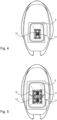
- the scooter 1 has a housing 3 for receiving and connecting the battery 2.
- the housing 3 is very easy to access, being located, in the example shown here, under the saddle 4 of the scooter.
- the area under the saddle 4 is, in a known manner, accessible by tilting the saddle 4.
- the scooter of the figure 1 is particularly well suited to rapid battery exchange, for example to replace a discharged battery with a charged battery.
- Replacing battery 2 on scooter 1 thus simply consists of opening saddle 4, extracting battery 2 from housing 3 by pulling, inserting a new battery into housing 3, and closing saddle 4.
- FIG. 2 An example of a battery 2 that can be used in the scooter of the figure 1 is represented at the figure 2 .
- the battery 2 comprises a set of electric cells, for example lithium-ion technologies, although any other battery technology is possible in the context of the present invention (in particular lead, nickel-cadmium, nickel-metal hydride, lithium -polymer, lithium-iron-phosphate, aluminum, etc.).
- the nominal voltage of the battery is adapted to the intended application, and can be, for example, 36V, 48V, 60V, 72V, or any other appropriate voltage.
- the battery 2 may include, in addition to the battery cells, one or more electronic cards, which may include in particular a microprocessor and, where appropriate, a memory. These electronic means can be intended to carry out various functions linked to the management of the battery, in particular its charge, to the recording of data relating to its use (voltage, charge/discharge currents, temporal information, etc.). These electronic means form a battery management system, commonly referred to by the English acronym BMS for “Battery Management System”.
- the face of the battery opposite the face on which the handle 5 is provided which can be called the base 7 of the battery, includes an electrical connector for the battery 8.
- the base 7 also constitutes a face on which the battery can be placed on the ground, and can thus include support pads 9.
- the term electrical connector is used in the singular, it is a set of several electrical contacts grouped and organized in the form of a socket , suitable for connection to a corresponding socket.
- the electrical connector of the battery 8 is called “female”, in that it is formed in the battery 2 and is adapted to receive a “male” electrical connector inserted therein.
- the electrical connector of the battery 8 is thus provided with a set of female contacts adapted to receive corresponding male contacts.
- the contacts can be arranged to allow connection of the battery in several orientations.
- the contacts can be symmetrical, namely a central contact and two contacts distributed on either side, allowing a connection in two orientations.
- the battery further comprises centering holes 10, allowing the centering of the battery in its receiving housing 3, and its guidance when connecting the electrical connector of the battery 8.
- the battery housing under the saddle 4 is advantageous with regard to the general balance of the scooter in use, and also due to the proximity to the propulsion motor.
- a connector support 11 which carries the electrical connector of the vehicle 12 (namely the scooter 1) intended to be connected to the electrical connector of the battery 8.
- FIG. 5 represents a detailed view of a battery housing according to another embodiment of the invention.
- Slot 3 is essentially identical to that of Figure 4 , but is suitable for receiving two batteries. This makes it possible to increase the autonomy of the vehicle, or to guarantee sufficient autonomy for a vehicle requiring significant power to move. This may concern a heavier vehicle, and/or one with a significant expected load, for example a vehicle intended for deliveries.
- Housing 3 thus comprises two contiguous wells, at the bottom of which two connector supports 11 are arranged.
- Each connector support 11 carries an electrical connector of the vehicle 12 intended to be connected to the electrical connector of a battery.
- the vehicle can have more than two batteries, for example three batteries.
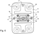
- FIG. 6 illustrates an example of connector support 11 which can be implemented in the invention.
- the connector support 11 is formed by a rigid plate 13, on which the electrical connector of the vehicle 12 is mounted.
- the electrical connector of the vehicle 12 is thus a male connector, adapted to be plugged into a connector electrical battery 8 corresponding.
- the vehicle's electrical connector 12 includes several male electrical contacts.
- a negative pole contact 14 is provided in the center and is intended to be connected to the negative terminal of the battery.
- Two positive pole contacts 15 are arranged on either side of the negative pole contact 14. The symmetrical arrangement of the positive pole contacts 15 allows connection in two opposite orientations of the battery 2 and its electrical connector of the battery 8 on the battery electrical connector 8.
- the vehicle's electrical connector 12 further comprises guide pads 16, allowing fine guidance of the connectors between them during their connection by plugging.
- the guide pads 16 of the vehicle's electrical connector 12 cooperate by shape correspondence with the electrical connector of the battery 8 when plugging.
- the connector support 11 includes centering pins 17 which penetrate into the centering holes 10 of the battery when it is connected.
- the electrical connector of the vehicle 12 can in fact be mounted floating on the connector support 11. According to such a floating assembly, the electrical connector of the vehicle 12 has two degrees of freedom, in the plane formed by the connector support, this is that is to say in this case by the rigid plate 13.
- some of these additional electrical contacts 18 can for example be used to allow data communication from and/or to the battery. These contacts allow the vehicle to communicate with the battery management system.
- one of the additional electrical contacts 18 may be shorter than the others, so that detection of its connection can serve to ensure that the battery is correctly installed, with correct connection of its connector.
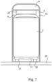
- FIG. 7 A first example of an embodiment is shown in Figure 7 .
- the elastic means are formed in this example of four elastic studs (commonly called silent blocks (registered trademark)).
- the elastic studs are linked near the four corners of the rigid plate 13, by fixing holes 22 (visible at the top). Figure 6 ).
- the elastic means must be chosen so as to allow movement of the battery both upwards and downwards.
- the prestress linked to the weight of the battery, and where appropriate the prestress exerted by element 23, are taken into account to choose the elastic means.
- the characteristics of the elastic means are determined adequately with regard to their shape, their number, their constituent material (or materials), etc.
- Rubber blocks four in number, with an elastic thickness of between 0.5 mm and 5 cm were used successfully.
- the very shape of the elastic pads can be used to achieve the desired flexibility, and/or to improve their damping properties. Hollow pads, comprising a opening, can thus be used. Studs made of several elastic materials, and where appropriate a damping material, can be used.
- the tray 19 is formed in two parts , namely a lower part 25 comprising the bottom 21 which is movable with respect to the structure, and an upper part 26, closed by the saddle 4, and which is fixed with respect to the structure of the vehicle 24
- the lower part 25 is in particular movable in vertical translation (in this embodiment of the invention in which the direction of introduction of the battery is vertical, generally the constituent parts of the containers 19 according to this second embodiment. being movable between them at least in said direction of introduction of the battery into housing 3) with respect to the upper part 26.
- the battery support can be integrally formed with the bottom of the tank 19, which also forms the bottom of the housing 3.
Landscapes
- Engineering & Computer Science (AREA)
- Mechanical Engineering (AREA)
- Transportation (AREA)
- Power Engineering (AREA)
- Life Sciences & Earth Sciences (AREA)
- Sustainable Development (AREA)
- Sustainable Energy (AREA)
- Chemical & Material Sciences (AREA)
- Combustion & Propulsion (AREA)
- Battery Mounting, Suspending (AREA)
- Arrangement Or Mounting Of Propulsion Units For Vehicles (AREA)
- Electric Propulsion And Braking For Vehicles (AREA)
Claims (13)
- Vorrichtung zum Empfangen einer Batterie (2) für ein elektrisches Fahrzeug, wobei die Vorrichtung beinhalteteine Aufnahme (3), die in einer Struktur des Fahrzeugs (24) eingerichtet ist, und angepasst ist, um mindestens eine Batterie (2) zu empfangen, wobei die Aufnahme (3) eine offene Seite zum Einsetzen der Batterie (2) in die Aufnahme (3) in einer sogenannten vertikalen Einsetzrichtung der Batterie beinhaltet,wobei die Aufnahme (3) einen Boden (21) gegenüber ihrer offenen Seite beinhaltet,wobei die Vorrichtung im Bereich des Bodens (21) eine Steckverbinder-Stütze (11) und einen elektrischen Steckverbinder des Fahrzeugs (12) beinhaltet, der an die Steckverbinder-Stütze (11) gebunden ist,wobei der elektrische Steckverbinder des Fahrzeugs (12) angepasst ist, um durch Einstecken in der Einsetzrichtung der Batterie mit einem entsprechenden elektrischen Steckverbinder der Batterie (8) zusammenzuwirken,wobei die Steckverbinder-Stütze (11) durch elastische Mittel mit der Struktur des Fahrzeugs (24) verbunden ist,wobei die Vorrichtung konfiguriert ist, damit die Batterie (2) durch einfaches translatorisches Einsetzen in die Aufnahme (3) angeschlossen werden kann;dadurch gekennzeichnet, dass die elastischen Mittel (20) aus einer Einheit an elastischen Stiften bestehen, die angepasst sind, um sich in der Einsetzrichtung der Batterie zu verformen, um eine vertikale Bewegung der Batterie nach oben und nach unten zu ermöglichen;und dadurch, dass die Vorrichtung weiter einen Deckel beinhaltet, der es ermöglicht, die offene Seite der Aufnahme in einer geschlossenen Position zu verschließen, oder in einer offenen Position freizugeben, wobei der Deckel in der geschlossenen Position eine zur Aufnahme (3) innere Seite beinhaltet, die mit einem elastischen Element (23) versehen ist, das angepasst ist, um sich an einer Seite der Batterie gegenüber dem elektrischen Steckverbinder der Batterie (8) anzulegen.
- Vorrichtung nach Anspruch 1, wobei die Vorrichtung konfiguriert ist, sodass die elastischen Stifte das Gewicht der Batterie tragen.
- Vorrichtung nach Anspruch 1 oder Anspruch 2, wobei der elektrische Steckverbinder des Fahrzeugs (12) schwimmend auf der Steckverbinder-Stütze (11) montiert ist, sodass er zwei Freiheitsgrade in einer Ebene aufweist, welche durch die Steckverbinder-Stütze gebildet wird.
- Vorrichtung nach einem der Ansprüche 1 bis 3, wobei die Aufnahme (3) eine prismatische Form mit einer nicht kreisrunden Basis aufweist, sodass die Wände der Aufnahme (3) die Batterie leiten, welche eine bis auf ein Spiel genaue entsprechende Form in der Einsetzrichtung der Batterie (2) aufweist.
- Vorrichtung nach einem der vorstehenden Ansprüche, wobei der Deckel ein Sattel (4) ist, der an die Struktur des Fahrzeugs (24) gebunden ist.
- Vorrichtung nach einem der vorstehenden Ansprüche, wobei das elastische Element (23) aus einem elastischen Schaumstoffblock gebildet ist.
- Vorrichtung nach Anspruch 6, wobei der Schaumstoff ein Schaumstoff aus Elastomer, beispielsweise aus Gummi, aus Polyurethan, oder aus Silikon ist.
- Vorrichtung nach einem der vorstehenden Ansprüche, wobei der Boden der Aufnahme (21) gegenüber der Struktur des Fahrzeugs (24) feststehend ist, und die Steckverbinder-Stütze (11) durch die elastischen Mittel (20) mit dem Boden verbunden ist.
- Vorrichtung nach einem der Ansprüche 1 bis 7, wobei die Steckverbinder-Stütze starr an den Boden der Aufnahme gebunden ist, oder durch den Boden der Aufnahme gebildet wird, und wobei der Boden der Aufnahme (21) durch die elastischen Mittel mit der Struktur des Fahrzeugs (24) verbunden ist.
- Vorrichtung nach einem der vorstehenden Ansprüche, wobei jeder elastische Stift aus einem oder mehreren Elementen aus Elastomer, beispielsweise aus Gummi, aus Polyurethan, oder aus Silikon gebildet ist.
- Vorrichtung nach einem der vorstehenden Ansprüche, wobei jeder elastische Stift hohl ist, oder eine Öffnung beinhaltet, die dessen Starrheit in der Einsetzrichtung der Batterie verringert.
- Vorrichtung nach einem der vorstehenden Ansprüche, wobei die elastischen Mittel eine Härte aufweisen, die zwischen Shore 00 10 und Shore A 100 liegt.
- Fahrzeug, insbesondere Elektroroller (1), der eine Vorrichtung nach einem der vorstehenden Ansprüche beinhaltet.
Applications Claiming Priority (1)
| Application Number | Priority Date | Filing Date | Title |
|---|---|---|---|
| FR2003972A FR3109472B1 (fr) | 2020-04-21 | 2020-04-21 | Dispositif de réception d’une batterie pour véhicule électrique et véhicule comportant un tel dispositif |
Publications (2)
| Publication Number | Publication Date |
|---|---|
| EP3900967A1 EP3900967A1 (de) | 2021-10-27 |
| EP3900967B1 true EP3900967B1 (de) | 2024-07-03 |
Family
ID=71452475
Family Applications (1)
| Application Number | Title | Priority Date | Filing Date |
|---|---|---|---|
| EP21168748.8A Active EP3900967B1 (de) | 2020-04-21 | 2021-04-16 | Vorrichtung zur aufnahme einer batterie eines elektrischen fahrzeugs und fahrzeug, das eine solche vorrichtung umfasst |
Country Status (3)
| Country | Link |
|---|---|
| EP (1) | EP3900967B1 (de) |
| ES (1) | ES2988586T3 (de) |
| FR (1) | FR3109472B1 (de) |
Families Citing this family (4)
| Publication number | Priority date | Publication date | Assignee | Title |
|---|---|---|---|---|
| IT202100011432A1 (it) * | 2021-05-05 | 2022-11-05 | Piaggio & C Spa | Veicolo elettrico o ibrido a sella cavalcabile comprendente una batteria ricaricabile estraibile ed un dispositivo di bloccaggio della batteria |
| MX2024003868A (es) * | 2021-10-22 | 2024-04-19 | Crown Equip Corp | Mecanismos de bloqueo de bateria, ensamblajes de baterias extraibles y vehiculos de manipulacion de materiales que incorporan los mismos. |
| EP4282696A1 (de) * | 2022-05-27 | 2023-11-29 | Mathieu | Batterie zur stromversorgung und ladeverfahren eines fahrzeugs |
| FR3147743A1 (fr) * | 2023-04-14 | 2024-10-18 | Psa Automobiles Sa | Vehicule automobile a propulsion electrique comprenant un module de batterie additionnelle |
Citations (2)
| Publication number | Priority date | Publication date | Assignee | Title |
|---|---|---|---|---|
| EP2280436B1 (de) * | 2009-07-30 | 2017-08-30 | Suzuki Motor Corporation | Entfernbares Batteriepack für elektrische Fahrzeuge und mit diesem Batteriepack ausgerüstetes elektrisches Fahrzeug |
| WO2020065868A1 (ja) * | 2018-09-27 | 2020-04-02 | 本田技研工業株式会社 | 鞍乗型車両のバッテリ着脱構造 |
Family Cites Families (3)
| Publication number | Priority date | Publication date | Assignee | Title |
|---|---|---|---|---|
| FR2947674B1 (fr) * | 2009-07-03 | 2012-11-30 | Sapt Groupe Sa | Support de connecteur |
| FR2964609B1 (fr) * | 2010-09-14 | 2012-09-28 | Renault Sa | Structure de vehicule automobile a batterie d'accumulateurs amovible |
| CN103050808B (zh) * | 2012-12-26 | 2015-09-09 | 深圳市台铃电动车有限公司 | 隐藏式电池盒自动连接装置 |
-
2020
- 2020-04-21 FR FR2003972A patent/FR3109472B1/fr active Active
-
2021
- 2021-04-16 ES ES21168748T patent/ES2988586T3/es active Active
- 2021-04-16 EP EP21168748.8A patent/EP3900967B1/de active Active
Patent Citations (2)
| Publication number | Priority date | Publication date | Assignee | Title |
|---|---|---|---|---|
| EP2280436B1 (de) * | 2009-07-30 | 2017-08-30 | Suzuki Motor Corporation | Entfernbares Batteriepack für elektrische Fahrzeuge und mit diesem Batteriepack ausgerüstetes elektrisches Fahrzeug |
| WO2020065868A1 (ja) * | 2018-09-27 | 2020-04-02 | 本田技研工業株式会社 | 鞍乗型車両のバッテリ着脱構造 |
Also Published As
| Publication number | Publication date |
|---|---|
| FR3109472B1 (fr) | 2022-08-26 |
| EP3900967A1 (de) | 2021-10-27 |
| FR3109472A1 (fr) | 2021-10-22 |
| ES2988586T3 (es) | 2024-11-21 |
Similar Documents
| Publication | Publication Date | Title |
|---|---|---|
| EP3900967B1 (de) | Vorrichtung zur aufnahme einer batterie eines elektrischen fahrzeugs und fahrzeug, das eine solche vorrichtung umfasst | |
| EP4029078A1 (de) | Strombatterie für ein fahrzeug | |
| FR3052925A1 (fr) | Dispositif portatif de devidage d'un cable electrique, notamment un cable de charge pour un vehicule electrique ou hybride | |
| FR2940201A1 (fr) | Systemes et ensemble de connexion pour la charge d'un vehicule electrique | |
| FR2685547A1 (fr) | Dispositif d'alimentation en energie d'un vehicule electrique. | |
| FR3056022A1 (fr) | Dispositif d'interconnexion electrique d'elements de batterie et batterie d'accumulateurs pourvue d'un tel dispositif | |
| FR3016085A3 (de) | ||
| FR2964609A1 (fr) | Structure de vehicule automobile a batterie d'accumulateurs amovible | |
| WO2013144466A1 (fr) | Coque pour téléphone mobile et terminal mobile | |
| EP3772760A1 (de) | Speichervorrichtung für elektrische energie, die an der aussenseite eines fahrzeugs vom typ fahrrad oder elektroroller befestigt werden kann | |
| EP0858172B1 (de) | Tragbares Gerät, und Batteriegehäuse des tragbaren Gerätes für Gebrauch von verschiedenen Batterietypen konstruiert | |
| FR3079356A1 (fr) | Socle d'accueil d'un terminal mobile et terminal mobile correspondant | |
| EP3900976B1 (de) | Batterie mit doppelkennung, station, system und verfahren zum austausch von batterien | |
| WO2022111996A1 (fr) | Interface electromecanique pour systeme automatique de gestion de batteries d'un drone | |
| FR2962696A1 (fr) | Charge sans contact d'une batterie de vehicule automobile. | |
| FR2988068A1 (fr) | Systeme automatique de stockage de cycles, cycle pour un tel systeme et utilisation d'une batterie pour un tel cycle. | |
| FR3010693A1 (fr) | Velo a assistance electrique | |
| FR2970600A1 (fr) | Dispositif de reception d'une pluralite de batteries. | |
| EP0407966B1 (de) | Herausnehmbarer Behälter für Batterien, insbesondere für Knopfzellen | |
| WO2024141923A1 (fr) | Module électrique pour batterie électrique | |
| EP4618274A1 (de) | Vorrichtung zum verbinden von zellen in einem batteriepack | |
| WO2014076412A1 (fr) | Lampadaire muni de prises de rechargement de vehicules | |
| FR3143221A1 (fr) | Interfaces pour équipements électroniques | |
| FR3060208A1 (fr) | Batterie d'accumulateur a boitier de connexion amovible et vehicule electrique ou hybride associe | |
| FR3132225A1 (fr) | Bouchon électronique rechargeable et socle de chargement |
Legal Events
| Date | Code | Title | Description |
|---|---|---|---|
| PUAI | Public reference made under article 153(3) epc to a published international application that has entered the european phase |
Free format text: ORIGINAL CODE: 0009012 |
|
| STAA | Information on the status of an ep patent application or granted ep patent |
Free format text: STATUS: THE APPLICATION HAS BEEN PUBLISHED |
|
| AK | Designated contracting states |
Kind code of ref document: A1 Designated state(s): AL AT BE BG CH CY CZ DE DK EE ES FI FR GB GR HR HU IE IS IT LI LT LU LV MC MK MT NL NO PL PT RO RS SE SI SK SM TR |
|
| B565 | Issuance of search results under rule 164(2) epc |
Effective date: 20210721 |
|
| STAA | Information on the status of an ep patent application or granted ep patent |
Free format text: STATUS: REQUEST FOR EXAMINATION WAS MADE |
|
| 17P | Request for examination filed |
Effective date: 20220414 |
|
| RBV | Designated contracting states (corrected) |
Designated state(s): AL AT BE BG CH CY CZ DE DK EE ES FI FR GB GR HR HU IE IS IT LI LT LU LV MC MK MT NL NO PL PT RO RS SE SI SK SM TR |
|
| STAA | Information on the status of an ep patent application or granted ep patent |
Free format text: STATUS: EXAMINATION IS IN PROGRESS |
|
| 17Q | First examination report despatched |
Effective date: 20220907 |
|
| RIC1 | Information provided on ipc code assigned before grant |
Ipc: B60L 50/60 20190101ALN20231221BHEP Ipc: B60L 50/64 20190101ALN20231221BHEP Ipc: B60L 53/80 20190101ALN20231221BHEP Ipc: B60L 53/16 20190101ALN20231221BHEP Ipc: B62J 43/16 20200101ALN20231221BHEP Ipc: B62J 9/14 20200101ALN20231221BHEP Ipc: B62J 1/12 20060101ALN20231221BHEP Ipc: B60L 53/00 20190101ALN20231221BHEP Ipc: B60K 1/04 20190101AFI20231221BHEP |
|
| GRAP | Despatch of communication of intention to grant a patent |
Free format text: ORIGINAL CODE: EPIDOSNIGR1 |
|
| STAA | Information on the status of an ep patent application or granted ep patent |
Free format text: STATUS: GRANT OF PATENT IS INTENDED |
|
| RIC1 | Information provided on ipc code assigned before grant |
Ipc: B60L 50/60 20190101ALN20240109BHEP Ipc: B60L 50/64 20190101ALN20240109BHEP Ipc: B60L 53/80 20190101ALN20240109BHEP Ipc: B60L 53/16 20190101ALN20240109BHEP Ipc: B62J 43/16 20200101ALN20240109BHEP Ipc: B62J 9/14 20200101ALN20240109BHEP Ipc: B62J 1/12 20060101ALN20240109BHEP Ipc: B60L 53/00 20190101ALN20240109BHEP Ipc: B60K 1/04 20190101AFI20240109BHEP |
|
| INTG | Intention to grant announced |
Effective date: 20240126 |
|
| GRAS | Grant fee paid |
Free format text: ORIGINAL CODE: EPIDOSNIGR3 |
|
| GRAA | (expected) grant |
Free format text: ORIGINAL CODE: 0009210 |
|
| STAA | Information on the status of an ep patent application or granted ep patent |
Free format text: STATUS: THE PATENT HAS BEEN GRANTED |
|
| AK | Designated contracting states |
Kind code of ref document: B1 Designated state(s): AL AT BE BG CH CY CZ DE DK EE ES FI FR GB GR HR HU IE IS IT LI LT LU LV MC MK MT NL NO PL PT RO RS SE SI SK SM TR |
|
| REG | Reference to a national code |
Ref country code: CH Ref legal event code: EP |
|
| REG | Reference to a national code |
Ref country code: DE Ref legal event code: R096 Ref document number: 602021015004 Country of ref document: DE |
|
| REG | Reference to a national code |
Ref country code: LT Ref legal event code: MG9D |
|
| REG | Reference to a national code |
Ref country code: NL Ref legal event code: MP Effective date: 20240703 |
|
| REG | Reference to a national code |
Ref country code: ES Ref legal event code: FG2A Ref document number: 2988586 Country of ref document: ES Kind code of ref document: T3 Effective date: 20241121 |
|
| PG25 | Lapsed in a contracting state [announced via postgrant information from national office to epo] |
Ref country code: PT Free format text: LAPSE BECAUSE OF FAILURE TO SUBMIT A TRANSLATION OF THE DESCRIPTION OR TO PAY THE FEE WITHIN THE PRESCRIBED TIME-LIMIT Effective date: 20241104 |
|
| REG | Reference to a national code |
Ref country code: AT Ref legal event code: MK05 Ref document number: 1699484 Country of ref document: AT Kind code of ref document: T Effective date: 20240703 |
|
| PG25 | Lapsed in a contracting state [announced via postgrant information from national office to epo] |
Ref country code: NL Free format text: LAPSE BECAUSE OF FAILURE TO SUBMIT A TRANSLATION OF THE DESCRIPTION OR TO PAY THE FEE WITHIN THE PRESCRIBED TIME-LIMIT Effective date: 20240703 |
|
| PG25 | Lapsed in a contracting state [announced via postgrant information from national office to epo] |
Ref country code: PT Free format text: LAPSE BECAUSE OF FAILURE TO SUBMIT A TRANSLATION OF THE DESCRIPTION OR TO PAY THE FEE WITHIN THE PRESCRIBED TIME-LIMIT Effective date: 20241104 Ref country code: NL Free format text: LAPSE BECAUSE OF FAILURE TO SUBMIT A TRANSLATION OF THE DESCRIPTION OR TO PAY THE FEE WITHIN THE PRESCRIBED TIME-LIMIT Effective date: 20240703 |
|
| PG25 | Lapsed in a contracting state [announced via postgrant information from national office to epo] |
Ref country code: NO Free format text: LAPSE BECAUSE OF FAILURE TO SUBMIT A TRANSLATION OF THE DESCRIPTION OR TO PAY THE FEE WITHIN THE PRESCRIBED TIME-LIMIT Effective date: 20241003 |
|
| PG25 | Lapsed in a contracting state [announced via postgrant information from national office to epo] |
Ref country code: FI Free format text: LAPSE BECAUSE OF FAILURE TO SUBMIT A TRANSLATION OF THE DESCRIPTION OR TO PAY THE FEE WITHIN THE PRESCRIBED TIME-LIMIT Effective date: 20240703 Ref country code: GR Free format text: LAPSE BECAUSE OF FAILURE TO SUBMIT A TRANSLATION OF THE DESCRIPTION OR TO PAY THE FEE WITHIN THE PRESCRIBED TIME-LIMIT Effective date: 20241004 Ref country code: PL Free format text: LAPSE BECAUSE OF FAILURE TO SUBMIT A TRANSLATION OF THE DESCRIPTION OR TO PAY THE FEE WITHIN THE PRESCRIBED TIME-LIMIT Effective date: 20240703 |
|
| PG25 | Lapsed in a contracting state [announced via postgrant information from national office to epo] |
Ref country code: BG Free format text: LAPSE BECAUSE OF FAILURE TO SUBMIT A TRANSLATION OF THE DESCRIPTION OR TO PAY THE FEE WITHIN THE PRESCRIBED TIME-LIMIT Effective date: 20240703 |
|
| PG25 | Lapsed in a contracting state [announced via postgrant information from national office to epo] |
Ref country code: LV Free format text: LAPSE BECAUSE OF FAILURE TO SUBMIT A TRANSLATION OF THE DESCRIPTION OR TO PAY THE FEE WITHIN THE PRESCRIBED TIME-LIMIT Effective date: 20240703 |
|
| PG25 | Lapsed in a contracting state [announced via postgrant information from national office to epo] |
Ref country code: AT Free format text: LAPSE BECAUSE OF FAILURE TO SUBMIT A TRANSLATION OF THE DESCRIPTION OR TO PAY THE FEE WITHIN THE PRESCRIBED TIME-LIMIT Effective date: 20240703 Ref country code: IS Free format text: LAPSE BECAUSE OF FAILURE TO SUBMIT A TRANSLATION OF THE DESCRIPTION OR TO PAY THE FEE WITHIN THE PRESCRIBED TIME-LIMIT Effective date: 20241103 |
|
| PG25 | Lapsed in a contracting state [announced via postgrant information from national office to epo] |
Ref country code: CZ Free format text: LAPSE BECAUSE OF FAILURE TO SUBMIT A TRANSLATION OF THE DESCRIPTION OR TO PAY THE FEE WITHIN THE PRESCRIBED TIME-LIMIT Effective date: 20240703 Ref country code: HR Free format text: LAPSE BECAUSE OF FAILURE TO SUBMIT A TRANSLATION OF THE DESCRIPTION OR TO PAY THE FEE WITHIN THE PRESCRIBED TIME-LIMIT Effective date: 20240703 |
|
| PG25 | Lapsed in a contracting state [announced via postgrant information from national office to epo] |
Ref country code: RS Free format text: LAPSE BECAUSE OF FAILURE TO SUBMIT A TRANSLATION OF THE DESCRIPTION OR TO PAY THE FEE WITHIN THE PRESCRIBED TIME-LIMIT Effective date: 20241003 |
|
| PG25 | Lapsed in a contracting state [announced via postgrant information from national office to epo] |
Ref country code: RS Free format text: LAPSE BECAUSE OF FAILURE TO SUBMIT A TRANSLATION OF THE DESCRIPTION OR TO PAY THE FEE WITHIN THE PRESCRIBED TIME-LIMIT Effective date: 20241003 Ref country code: PL Free format text: LAPSE BECAUSE OF FAILURE TO SUBMIT A TRANSLATION OF THE DESCRIPTION OR TO PAY THE FEE WITHIN THE PRESCRIBED TIME-LIMIT Effective date: 20240703 Ref country code: NO Free format text: LAPSE BECAUSE OF FAILURE TO SUBMIT A TRANSLATION OF THE DESCRIPTION OR TO PAY THE FEE WITHIN THE PRESCRIBED TIME-LIMIT Effective date: 20241003 Ref country code: LV Free format text: LAPSE BECAUSE OF FAILURE TO SUBMIT A TRANSLATION OF THE DESCRIPTION OR TO PAY THE FEE WITHIN THE PRESCRIBED TIME-LIMIT Effective date: 20240703 Ref country code: IS Free format text: LAPSE BECAUSE OF FAILURE TO SUBMIT A TRANSLATION OF THE DESCRIPTION OR TO PAY THE FEE WITHIN THE PRESCRIBED TIME-LIMIT Effective date: 20241103 Ref country code: HR Free format text: LAPSE BECAUSE OF FAILURE TO SUBMIT A TRANSLATION OF THE DESCRIPTION OR TO PAY THE FEE WITHIN THE PRESCRIBED TIME-LIMIT Effective date: 20240703 Ref country code: GR Free format text: LAPSE BECAUSE OF FAILURE TO SUBMIT A TRANSLATION OF THE DESCRIPTION OR TO PAY THE FEE WITHIN THE PRESCRIBED TIME-LIMIT Effective date: 20241004 Ref country code: FI Free format text: LAPSE BECAUSE OF FAILURE TO SUBMIT A TRANSLATION OF THE DESCRIPTION OR TO PAY THE FEE WITHIN THE PRESCRIBED TIME-LIMIT Effective date: 20240703 Ref country code: CZ Free format text: LAPSE BECAUSE OF FAILURE TO SUBMIT A TRANSLATION OF THE DESCRIPTION OR TO PAY THE FEE WITHIN THE PRESCRIBED TIME-LIMIT Effective date: 20240703 Ref country code: BG Free format text: LAPSE BECAUSE OF FAILURE TO SUBMIT A TRANSLATION OF THE DESCRIPTION OR TO PAY THE FEE WITHIN THE PRESCRIBED TIME-LIMIT Effective date: 20240703 Ref country code: AT Free format text: LAPSE BECAUSE OF FAILURE TO SUBMIT A TRANSLATION OF THE DESCRIPTION OR TO PAY THE FEE WITHIN THE PRESCRIBED TIME-LIMIT Effective date: 20240703 |
|
| REG | Reference to a national code |
Ref country code: DE Ref legal event code: R097 Ref document number: 602021015004 Country of ref document: DE |
|
| PG25 | Lapsed in a contracting state [announced via postgrant information from national office to epo] |
Ref country code: SM Free format text: LAPSE BECAUSE OF FAILURE TO SUBMIT A TRANSLATION OF THE DESCRIPTION OR TO PAY THE FEE WITHIN THE PRESCRIBED TIME-LIMIT Effective date: 20240703 Ref country code: RO Free format text: LAPSE BECAUSE OF FAILURE TO SUBMIT A TRANSLATION OF THE DESCRIPTION OR TO PAY THE FEE WITHIN THE PRESCRIBED TIME-LIMIT Effective date: 20240703 Ref country code: DK Free format text: LAPSE BECAUSE OF FAILURE TO SUBMIT A TRANSLATION OF THE DESCRIPTION OR TO PAY THE FEE WITHIN THE PRESCRIBED TIME-LIMIT Effective date: 20240703 |
|
| PG25 | Lapsed in a contracting state [announced via postgrant information from national office to epo] |
Ref country code: EE Free format text: LAPSE BECAUSE OF FAILURE TO SUBMIT A TRANSLATION OF THE DESCRIPTION OR TO PAY THE FEE WITHIN THE PRESCRIBED TIME-LIMIT Effective date: 20240703 |
|
| PGFP | Annual fee paid to national office [announced via postgrant information from national office to epo] |
Ref country code: FR Payment date: 20250331 Year of fee payment: 5 |
|
| PG25 | Lapsed in a contracting state [announced via postgrant information from national office to epo] |
Ref country code: SK Free format text: LAPSE BECAUSE OF FAILURE TO SUBMIT A TRANSLATION OF THE DESCRIPTION OR TO PAY THE FEE WITHIN THE PRESCRIBED TIME-LIMIT Effective date: 20240703 |
|
| PLBE | No opposition filed within time limit |
Free format text: ORIGINAL CODE: 0009261 |
|
| STAA | Information on the status of an ep patent application or granted ep patent |
Free format text: STATUS: NO OPPOSITION FILED WITHIN TIME LIMIT |
|
| 26N | No opposition filed |
Effective date: 20250404 |
|
| PGFP | Annual fee paid to national office [announced via postgrant information from national office to epo] |
Ref country code: ES Payment date: 20250507 Year of fee payment: 5 |
|
| PGFP | Annual fee paid to national office [announced via postgrant information from national office to epo] |
Ref country code: IT Payment date: 20250429 Year of fee payment: 5 |
|
| PG25 | Lapsed in a contracting state [announced via postgrant information from national office to epo] |
Ref country code: SE Free format text: LAPSE BECAUSE OF FAILURE TO SUBMIT A TRANSLATION OF THE DESCRIPTION OR TO PAY THE FEE WITHIN THE PRESCRIBED TIME-LIMIT Effective date: 20240703 |
|
| REG | Reference to a national code |
Ref country code: DE Ref legal event code: R119 Ref document number: 602021015004 Country of ref document: DE |
|
| REG | Reference to a national code |
Ref country code: CH Ref legal event code: H13 Free format text: ST27 STATUS EVENT CODE: U-0-0-H10-H13 (AS PROVIDED BY THE NATIONAL OFFICE) Effective date: 20251125 |
|
| PG25 | Lapsed in a contracting state [announced via postgrant information from national office to epo] |
Ref country code: LU Free format text: LAPSE BECAUSE OF NON-PAYMENT OF DUE FEES Effective date: 20250416 |
|
| PG25 | Lapsed in a contracting state [announced via postgrant information from national office to epo] |
Ref country code: MC Free format text: LAPSE BECAUSE OF FAILURE TO SUBMIT A TRANSLATION OF THE DESCRIPTION OR TO PAY THE FEE WITHIN THE PRESCRIBED TIME-LIMIT Effective date: 20240703 |
|
| GBPC | Gb: european patent ceased through non-payment of renewal fee |
Effective date: 20250416 |
|
| REG | Reference to a national code |
Ref country code: BE Ref legal event code: MM Effective date: 20250430 |
|
| PG25 | Lapsed in a contracting state [announced via postgrant information from national office to epo] |
Ref country code: DE Free format text: LAPSE BECAUSE OF NON-PAYMENT OF DUE FEES Effective date: 20251104 |
|
| PG25 | Lapsed in a contracting state [announced via postgrant information from national office to epo] |
Ref country code: GB Free format text: LAPSE BECAUSE OF NON-PAYMENT OF DUE FEES Effective date: 20250416 |
|
| PG25 | Lapsed in a contracting state [announced via postgrant information from national office to epo] |
Ref country code: BE Free format text: LAPSE BECAUSE OF NON-PAYMENT OF DUE FEES Effective date: 20250430 |
|
| PG25 | Lapsed in a contracting state [announced via postgrant information from national office to epo] |
Ref country code: CH Free format text: LAPSE BECAUSE OF NON-PAYMENT OF DUE FEES Effective date: 20250430 |
|
| PG25 | Lapsed in a contracting state [announced via postgrant information from national office to epo] |
Ref country code: IE Free format text: LAPSE BECAUSE OF NON-PAYMENT OF DUE FEES Effective date: 20250416 |