EP3901408A1 - Plattenstützstruktur - Google Patents
Plattenstützstruktur Download PDFInfo
- Publication number
- EP3901408A1 EP3901408A1 EP19900810.3A EP19900810A EP3901408A1 EP 3901408 A1 EP3901408 A1 EP 3901408A1 EP 19900810 A EP19900810 A EP 19900810A EP 3901408 A1 EP3901408 A1 EP 3901408A1
- Authority
- EP
- European Patent Office
- Prior art keywords
- tile panel
- tile
- horizontal frame
- fixed
- vertical frame
- Prior art date
- Legal status (The legal status is an assumption and is not a legal conclusion. Google has not performed a legal analysis and makes no representation as to the accuracy of the status listed.)
- Granted
Links
Images






Classifications
-
- E—FIXED CONSTRUCTIONS
- E04—BUILDING
- E04F—FINISHING WORK ON BUILDINGS, e.g. STAIRS, FLOORS
- E04F13/00—Coverings or linings, e.g. for walls or ceilings
- E04F13/07—Coverings or linings, e.g. for walls or ceilings composed of covering or lining elements; Sub-structures therefor; Fastening means therefor
- E04F13/08—Coverings or linings, e.g. for walls or ceilings composed of covering or lining elements; Sub-structures therefor; Fastening means therefor composed of a plurality of similar covering or lining elements
- E04F13/0801—Separate fastening elements
- E04F13/0803—Separate fastening elements with load-supporting elongated furring elements between wall and covering elements
- E04F13/081—Separate fastening elements with load-supporting elongated furring elements between wall and covering elements with additional fastening elements between furring elements and covering elements
- E04F13/083—Hooking means on the back side of the covering elements
-
- E—FIXED CONSTRUCTIONS
- E04—BUILDING
- E04F—FINISHING WORK ON BUILDINGS, e.g. STAIRS, FLOORS
- E04F13/00—Coverings or linings, e.g. for walls or ceilings
- E04F13/07—Coverings or linings, e.g. for walls or ceilings composed of covering or lining elements; Sub-structures therefor; Fastening means therefor
- E04F13/08—Coverings or linings, e.g. for walls or ceilings composed of covering or lining elements; Sub-structures therefor; Fastening means therefor composed of a plurality of similar covering or lining elements
- E04F13/0801—Separate fastening elements
- E04F13/0803—Separate fastening elements with load-supporting elongated furring elements between wall and covering elements
- E04F13/0805—Separate fastening elements with load-supporting elongated furring elements between wall and covering elements with additional fastening elements between furring elements and the wall
- E04F13/0808—Separate fastening elements with load-supporting elongated furring elements between wall and covering elements with additional fastening elements between furring elements and the wall adjustable in several directions one of which is perpendicular to the wall
-
- E—FIXED CONSTRUCTIONS
- E04—BUILDING
- E04F—FINISHING WORK ON BUILDINGS, e.g. STAIRS, FLOORS
- E04F13/00—Coverings or linings, e.g. for walls or ceilings
- E04F13/07—Coverings or linings, e.g. for walls or ceilings composed of covering or lining elements; Sub-structures therefor; Fastening means therefor
- E04F13/08—Coverings or linings, e.g. for walls or ceilings composed of covering or lining elements; Sub-structures therefor; Fastening means therefor composed of a plurality of similar covering or lining elements
- E04F13/0862—Coverings or linings, e.g. for walls or ceilings composed of covering or lining elements; Sub-structures therefor; Fastening means therefor composed of a plurality of similar covering or lining elements composed of a number of elements which are identical or not, e.g. carried by a common web, support plate or grid
-
- E—FIXED CONSTRUCTIONS
- E04—BUILDING
- E04F—FINISHING WORK ON BUILDINGS, e.g. STAIRS, FLOORS
- E04F13/00—Coverings or linings, e.g. for walls or ceilings
- E04F13/07—Coverings or linings, e.g. for walls or ceilings composed of covering or lining elements; Sub-structures therefor; Fastening means therefor
- E04F13/08—Coverings or linings, e.g. for walls or ceilings composed of covering or lining elements; Sub-structures therefor; Fastening means therefor composed of a plurality of similar covering or lining elements
- E04F13/14—Coverings or linings, e.g. for walls or ceilings composed of covering or lining elements; Sub-structures therefor; Fastening means therefor composed of a plurality of similar covering or lining elements stone or stone-like materials, e.g. ceramics concrete; of glass or with an outer layer of stone or stone-like materials or glass
Definitions
- the present invention relates to a tile panel support structure that can follow the swinging of a building induced by the earthquake or similar movement when construction of the building intends to employ a method for installing a large tile panel by a dry method.
- PC Plate Precast Concrete Plate
- ALC Panel Autoclaved Lightweight Concrete Panel
- ECP Extruded Cement Plate
- the outer walls are finished by sticking tiles or stone on the outer wall surface.
- a wet method or a dry method is usually employed. In the wet method, tiles or similar finishing materials are stuck directly on the outer wall using mortar. In the dry method, the tiles or similar materials are hanged on the supporting bracket fixed to the outer walls then adhered thereto using elastic glue.
- Patent Literature 2 an invention on a securing method has been disclosed, wherein the foundation material, to which the tiles are secured, itself is attached movable in the horizontal direction relative to the building frame.
- An object of the present invention is therefore to provide a tile panel support structure that is able to follow the building-swinging induced by the earthquake or similar movement for the case where a large-size tile is installed by a dry method.
- the present invention provides a large tile panel support structure to be attached to a building wall by a dry method.
- the feature of the invented tile panel support structure includes the following:
- the further feature of the tile panel support structure of the present invention includes an arrangement in which the tile receiving bracket that supports the bottom of the tile is fixed to the tile panel.
- the feature of the tile panel support structure of the present invention includes an arrangement that the vertical frame has an engaging slit for hanging on the horizontal frame and the horizontal frame is made up of an upper fin and a middle web connected from the upper fin. On the middle web, the load-bearing bracket rests.
- a feature of the tile panel support structure includes an aspect that the supporting bracket of the support structure is given a cut-off at its corners so that the corners do not hit the vertical frame when the wall material tilts.
- the tile panel support structure of the present invention for attaching plural tile panels to building wall material further includes the following features.
- the invented structure is comprised of:
- the feature of the tile panel support structure described above further includes the following: the horizontal frame is arranged between one tile panel and another tile panel immediately above and has a rise prevention plate fixed to prevent the above-stated one tile panel from rising toward that another tile panel.
- the tile panel is a fireproof panel.
- the present invention even when a large tile is installed by a dry method, it can follow swinging induced by earthquakes. Even a tile panel is large and heavy, the distortion occurred in the tile panel can be absorbed even if the amplitude of the swinging becomes larger because the invented supporting structure supports the tile panel at one point which allows right-to-left oscillation.
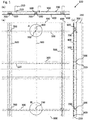
- Figure 1 shows a general view of the tile panel support structure, where the sketch (a) is a front view, (b) is a plan view, and (c) is a right-side elevation. Further note that the outward direction of the building is denoted as “front” (outside) and inward direction “rear” (backside). In addition, in the front view (a), the tile panel is shown as if transparent (this also applies to Figure 2 and Figure 11 ).
- a tile panel 400 is installed by a dry method on a wall material 200 of a building 100.
- the wall material 200 is a construction material to be used as an outer wall of the building body 100.
- PC plate precast concrete plate
- ALC panel Autoclaved Lightweight Concrete Panel
- ECP Extruded Cement Plate
- the wall material 200 is fixed with a screw 220 using a furring strip 210 as a foundation.
- the furring strip 210 is a longitudinally extended shape steel having a C-shaped cross-section (such as C-channel).
- a creasing 230 may be installed.
- plural horizontal frames 300 are secured.
- plural vertical frames 500 are fixed.
- the tile panel 400 is attached to the wall material 200 by hanging the vertical frame 500 on the horizontal frame 300.
- the horizontal frame 300 is hardware that extends in the crosswise direction and is fixed to the front face of the wall material 200 in the multiple positions from top to bottom. Between the uppermost horizontal frame 300 installed around the top of the tile panel 400 and the lowermost horizontal frame 300 installed around the bottom of the tile panel 400, any number of horizontal frames 300 can additionally be installed.
- the horizontal frame 300 may be fixed to the wall material 200 at the position of the furring strip 210 using the screw 220 that fixes the wall material 200.
- the tile panel 400 is a decorative material, to which one large tile or plural number of small tiles are glued.
- the tile in this purpose includes stone formed in a thin sheet other than plate materials such as ceramic plates.
- the tile panel 400 may be manufactured by gluing tiles in advance, or alternatively, tiles may be glued when installing the panel on the wall material 200. Note that, when the tile panel 400 becomes large, it will be greatly affected when the building 100 is distorted by shaking such as the earthquake.
- the vertical frame 500 is hardware extending vertically, they are arranged in plurality on the rear of the tile panel 400.
- the vertical frame 500 is arranged at least at the left end and in the middle and at the right end of the tile panel 400.
- the vertical frame 500 may be arranged further at any position between these left-, middle-, and right-position.
- a load-bearing bracket 600 is fixed.
- the load-bearing bracket 600 is attached to the center-positioned the vertical frame 500 in alignment with the position where the horizontal frame 300 of the uppermost is fixed.
- One load-bearing bracket 600 is enough for one tile panel 400.
- the load-bearing bracket 600 rests on the horizontal frame 300 when the vertical frame 500 is hung on the horizontal frame 300.
- the load of the tile panel 400 is imposed on the load-bearing bracket 600 and that load is borne at one-point on the contact point with the horizontal frame 300.
- a supporting bracket 700 fixed on the horizontal frame 300.
- the supporting bracket 700 is attached to the horizontal frames 300 of the uppermost and lowermost position.
- the attaching position of the supporting plate 700 is the location matched at least with the vertical frame 500 on the left end, in the middle, and on the right end. Alternatively, the attaching position can be the place in alignment with the fixing position of the vertical frame 500 located in the middle or can be the horizontal frame 300 located in the middle.
- the vertical frame 500 is held by the supporting plate 700 so that the tile panel 400 will not deviate crosswise when the vertical frame 500 is hung on the horizontal frame 300.
- a tile receiving hardware 800 which supports the underside of the tile is fixed.
- the tile receiving hardware 800 is hardware having a fin sticking out toward the near side so that the bottom face of the tile rests thereon.
- the tile receiving hardware 800 is required only to be fixed to the underside of the tile panel 400 using the screw fixing the vertical frame 500 to the tile panel 400.
- Figure 2 shows the enlarged view of the portion A (which appears in the upper middle part of Figure 1 encircled with a dotted circle) and its vicinity showing the tile panel support structure.
- the sketch (a) is an enlarged front view, (b) a plan view, and (c) a right-side elevation.
- the tile panel 400 is not secured to the wall material 200 and supported at one-point by the load-bearing bracket 600.
- the tile panel 400 is held by the supporting bracket 700 so as not to deviate positionally.
- the tile panel 400 is comprised of a foundation 420 like a magnesium plate and a tile 410 glued thereon by a glue 430 such as an elastic adhesive.
- a glue 430 such as an elastic adhesive.
- the vertical frame 500 is fixed to the rear of the foundation 420 by penetrating a screw from its front side to the rear side.
- the load-bearing bracket 600 is fixed with a screw 440a.
- the supporting bracket 700 is fixed using a screw 440b.
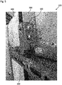
- Figure 3 is a perspective rear view to show the state in which the vertical frame is hung on the horizontal frame of the tile panel support structure. (The wall material is not shown for simplicity.)
- Figure 4 is a perspective front view to show the state in which the supporting bracket is arranged at the position of the vertical frame of the tile panel support structure. (The tile panel is not shown for simplicity.)
- Figure 5 is a perspective rear view to show the state of one-point supporting by the load-bearing bracket of the tile panel support structure. (The wall material is not shown for simplicity.)
- the vertical frame 500 is hung at the position of the horizontal frame 300 where the supporting bracket 700 is attached to.
- the supporting bracket 700 is hung on the front side and the load-bearing bracket 600 on the rear side.
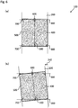
- Figure 6 is a front view to show states of distortion occurred in the building that has the tile panel support structure, wherein the sketch (a) shows a state no distortion occurred and (b) shows a state distortion occurred. If the earthquake occurs, a building shakes and the amplitude of shaking of the building induced by the earthquake at higher floors is larger than that of at lower floors as Figure 6 shows. This shaking causes a tilt of the building 100 resulting in distortion, which produces a large positional deviation difference 240 between the top and bottom of the tile panel 400.
- the tile panel 400 is not glued to the wall material 200 but supported with load-bearing bracket 600 positioned in the center of the tile panel 400 so as to allow following the shaking.
- the tile panel 400 tilts so that the vertical frame 500 fixed to the tile panel 400 matches to the position of the supporting bracket 700 on the horizontal frame 300 fixed to the wall material 200. That is, the tile panel 400 tilts following the tilt of the building 100.
- Figure 7 shows the horizontal frame of the tile panel support structure, wherein the sketch (a) shows a front view, (b) a plan view, and (c) a right-side elevation.
- Figure 8 shows the vertical frame of the tile panel support structure, wherein the sketch (a) shows a front view, (b) a plan view, and (c) a right-side elevation.
- Figure 9 shows the load-bearing bracket of the tile panel support structure, wherein the sketch (a) shows a front view, (b) a plan view, and (c) a right-side elevation.
- Figure 10 shows the supporting plate of the tile panel support structure, wherein the sketch (a) shows a front view, (b) a plan view, and (c) a right-side elevation.
- the horizontal frame 300 is a metalwork of horizontally-long plate material, which is folded to have a crank-shape cross-section.
- the horizontal frame 300 is made up of an upper fin 310 that perpendicularly rises formed on the front, a lower fin 330 that perpendicularly hung down formed on the rear, and a middle web 320 that connects the bottom end of the upper fin 310 and the top end of the lower fin 330.
- the upper fin 310 is a separating portion to give an allowance between the wall material 200 to hang the vertical frame 500 thereon and the supporting bracket 700 also can be fixed thereto.
- the middle web 320 is a part on which the load-bearing bracket 600 rests.
- the lower fin 330 is a portion to be fixed to the wall material 200.
- the lower fin 330 has alternately an elongated securing hole 340 and a circular securing hole 340a allowing a securing screw to be passed at any position.
- the vertical frame 500 is a metalwork of vertically-long plate material, which is bent to form a U-shape cross-section.
- the vertical frame 500 is made up of a vertical side fin 510 formed on the left, a vertical side fin 510 formed on the right, and a bottom web 520 that connects the front ends of vertical side fins 510 on the left and right.
- the vertical side fin 510 is the portion that protrudes rearward for hanging on the horizontal frame 300.
- the load-bearing bracket 600 also can be attached.
- the vertical side fin 510 has an engaging slit 530 for hanging on the horizontal frame 300 thereon.
- the engaging slit 530 is a cut-out portion of the vertical frame 500, which is provided so that its position will match the position of the horizontal frame 300.
- the cut-out portion has a slit in the upper part thereof to form a lug part which extends down in a hook shape so as to be hung on the upper fin 310 of the horizontal frame 300.
- a securing hole 540 is drilled in the location around the upper portion of the engaging slit 530. This hole allows the screw 440a penetration tightening when the load-bearing bracket 600 is installed so as to cross behind from the vertical fin 510 on the left to the vertical fin 510 on the right.
- the bottom web 520 is the portion that is fixed to the tile panel 400.
- the load-bearing bracket 600 is a metalwork of plate material, of which cross-section is an inverted U-shape.
- the load-bearing bracket 600 is made up of a vertical side fin 610 formed on the left, a vertical side fin 610 formed on the right, and a rear web 620 that connects the rear ends of the vertical side fins 610 on the left and right, and made up of a lug part 630 that protrudes downward from the rear web 620.
- the vertical side fin 610 is the part to be fixed to the vertical frame 500.
- the space between the vertical side fins 610 on the left side and on the right side is the same as the width of the vertical frame 500 (including its plate thickness).
- the load-bearing bracket 600 is put over the rear of the vertical frame 500 so as to be covered with the rear web 620.
- a securing hole 660 is drilled also on the vertical side fin 610 in alignment with the position of the securing hole 540 in the vertical frame 500 so as to make the screw 440a can pass through. Further, to prevent the engaging slit 530, which is for hanging the vertical side fin 500 on the horizontal frame 300, from being closed by the vertical side fin 610, a cutout 650 is provided in the vertical side fin 610 in alignment with the position of the engaging slit 530 of the vertical frame 500.
- the lower end of the lug part 630 has a curvature part 640 having protruding shape.
- the curvature part 640 of the lug part 630 rests on the middle web 320 of the horizontal frame 300, wherein only one point on the curvature part 640 rests on the horizontal frame 300.
- the load of the tile panel 400 concentrates at that point.
- the curvature part allows the tile panel 400 to tilt.
- the vertical length of the lug part 630 is determined to be such a length as the load of the tile panel 400 will not be imposed when the vertical frame 500 is hung on the horizontal frame 300 making the engaging slit 530 of the vertical frame 500 sit on the top end of the upper fin 310 of the horizontal frame 300.
- the supporting plate 700 is a folded metalwork having a U-shaped vertical cross-section.
- the supporting bracket 700 is made up of horizontal side fins 710 on the top side and on the bottom side, and a rear web 720 that connects their rear ends.
- the horizontal side fins 710 are the portion made to protrude toward the front side from the horizontal frame 300.
- the width of the horizontal side fins 710 is a width that can be inserted between the vertical side fins 510 on the left and on the right.
- a securing hole 740 is drilled in the rear web 720. The screw 440b can pass through the securing hole 740 when fixing on the upper fin 310 of the horizontal frame 300.
- a cut-off 730 is formed so that the corner of the wall material 200 does not hit the vertical frame 500 when the wall material 200 tilts.
- the cut-off 730 can be formed in a style of either diagonal cut or rounding.
- Figure 11 shows the enlarged view of the portion B (which appears in the lower center part of Figure 1 encircled with a dotted circle) and its vicinity showing the tile support structure.
- the sketch (a) is a front view, (b) a plan view, and (c) a right-side elevation.
- the sketch (a) shows the tile panel transparently for simplicity.
- Figure 12 shows the tile receiving hardware of the tile panel support structure.
- the sketch (a) is a front view, (b) is a plan view, and (c) is a right-side elevation.
- the supporting plate 700 fixed to the horizontal frame 300 into the vertical frame 500 prevents the crosswise positional deviation of the tile panel 400.
- the supporting bracket 700 is movable along with the vertical frame 500.
- the supporting bracket 700 is fixed to either or both the uppermost-positioned and the lowermost-positioned horizontal frames 300 on which position at least the vertical frame 500 is fixed.
- the tile panel 400 is made up of the tile 410 simply stuck on the foundation 420 with the glue 430. Therefore, the tile panel 400 is supported at its bottom by the tile receiving hardware 800.
- the tile receiving hardware 800 is put between the foundation 420 and the vertical frame 500 using a screw 440 that is also used for fixing the vertical frame 500 on the tile panel 400.
- the tile receiving hardware 800 is a metalwork of plate metal longitudinally-long, which is bent to have an L-shape cross-section.
- the tile receiving hardware 800 is made up of a vertical rear fin 810 that perpendicularly rises on the rear and a lower horizontal fin 820 connected thereto protruding frontward from the lower end of the vertical rear fin 810.
- the tile receiving hardware 800 may have the same width as that of the tile panel 400.
- the vertical rear fin 810 is the part that is fixed to the tile panel 400.
- the lower horizontal fin 820 is the part on which the tile 410 rests. That fin is required to protrude frontward only by the thickness of the tile 410.
- the protrusion may be provided partly or at intervals since the fin is only for supporting the tile 410.
- tile panel support structure is described in an example where a fireproof panel is used.
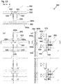
- FIG. 13 shows, plural tile panels 950 and 950a of fireproof property are attached to a fireproof panel 900 after the unevenness of the wall material 990 is adjusted using an unevenness adjusting hardware 980.
- a joint 950b between the tile panels 950 and 950a can be filled with a material such as a fireproof sealant.
- the wall material 990 is a material such as concrete or cement plate, into which bolts or anchor bolts are then driven, and the unevenness adjusting hardware 980 is attached to the wall material 990.
- the unevenness adjusting hardware 980 is arranged to bridge vertically adjacent tile panels 950 and 950a to form them in one series of panels and is used as hardware for installing the tile panels 950 and 950a by a dry method.
- the tile panel 950 is a porcelain ceramic tile or similar material, where arrayed plural tiles can also be employable.
- a fireproof plate 960 and 960a are glued (using elastic or mineral glue) to give fireproof property.
- the fireproof plates 960 and 960a are magnesium plates for example. Using such plates in a stack is also an employable style.
- the fireproof panel 900 is comprised of the following:
- the horizontal frame 910 is arranged between tile panel 950 adjacent below and the tile panel 950a adjacent above and is fixed with a screw on the unevenness adjusting hardware 980.
- the lower part of the horizontal frame 910 supports the tile panel 950 adjacent below, and the upper part of the horizontal frame 910 supports the tile panel 950a adjacent above.
- the horizontal frame 910 and the tile panels 950 and 950a are fixed removably, not fixed directly.
- the vertical frame 970 uses a square pipe of metal or resin and fixed at the center of the tile panel 950 (950a) with glue.
- the horizontal frame 910 and the vertical frame 970 are secured at the position where they intersect or near such intersection position.
- the supporting bracket 930 holds the vertical frame 970 to prevent the positional crosswise deviation of the tile panel 950 (950a).
- the supporting bracket 930 is fixed to the horizontal frame 910 with screws on the positions, for example, immediate right and immediate left of the vertical frame 970 so that the vertical frame 970 is sandwiched between supporting brackets 930.
- the supporting bracket 930 for the prevention of crosswise positional deviation of tile panel 950 immediate below and a supporting bracket 930a for the prevention of crosswise positional deviation the tile panel 950a immediate above may be provided.
- the load-bearing bracket 920 is fixed to the vertical frame 970 with screws or the like near the position where the vertical frame 970 and the horizontal frame 910 intersect.
- the load-bearing bracket 920 is attached to the upper part of the tile panel 950 below and rests on the horizontal frame 910 to support at one point the load of the tile panel 950 imposed on the horizontal frame 910.
- a fixing bracket 920a may be attached to the lower part of the panel 950a above.
- a rise prevention plate 940 is fixed to the horizontal frame 910 with screws or the like at a position between the tile panel 950 below and the tile panel 950a above.
- the tile panel 950 below is held down so as not to rise toward the tile panel 950a above, and even if the tile panel 950 hits causing tilt, it can rotate accordingly.
- the horizontal frame 910 is a folded metalwork of laterally long metal plate.
- the horizontal frame 910 is made up of a lower side receiver 911 in the lower part, an upper side receiver 912 in the upper part, and an intermediate part 913 in the center.
- the lower side receiver 911 is a portion in which the lower portion of the horizontal frame 910 is folded back in a hook shape toward the near side, and the load-bearing bracket 920 is hung inside of the hook shape bent back.
- the supporting bracket 930 is fixed to a lower front bend 911a.
- the upper side receiver 912 is a portion in which the upper part of the horizontal frame 910 is bent toward the near side in a crank shape, and the fixing bracket 920a is hung on the inner part of the crank shape. Further, the supporting bracket 930a is fixed to an upper front bend 912a.
- the intermediate part 913 is a flat portion in the middle portion of the horizontal frame 910 and is in contact with the unevenness adjustment hardware 980.
- Plural securing holes 914 and 914a such as elongated holes or round holes penetrate at an interval in the intermediate part 913, which is fixed to the unevenness adjusting metal hardware 980 through screws or the like.
- the load-bearing bracket 920 is metalwork having a cross-section of an inverted U shape made by bending sheet metal.
- the load-bearing bracket 920 is made up of wings 921 on the left and right side, and an intermediate part 922.
- the wing 921 is a part to be fixed to the vertical frame 970, and the spacing between the left-wing and the right-wing is the same as the width of the vertical frame 970 and is attached so as to cover the vertical frame 970.
- Plural securing holes 926 are drilled-through in the wings 921 on the right and left, which are fixed to the vertical frame 970 through screws or the like.
- the intermediate part 922 is a part connecting the wings 921 on the left and right.
- the lower part of the intermediate part 922 extends downward below the wing 921 to form a lug part 923.
- the bottom end of the lug part 923 is formed into a curvature part 924 that has a downward-convex shape.
- the lug part 923 is a portion that enters the lower side receiver 911 of the horizontal frame 910 and rests on the lower side receiver 911 with any one point on the curvature part 924 as a tip. Further, the lower portion of the wing 921 is also a portion that enters the lower side receiver 911 of the horizontal frame 910, and at least the portion that overlaps with the vertical frame 970 is formed in a cut-off 925.
- the load of the tile panel 950 imposed on the horizontal frame 910 concentrates on the contact point between the curvature part 924 and the lower side receiver 911. Since the horizontal frame 910 bears the load of the tile panel 950 at one point, the tile panel 950 can swing following shaking such as the earthquake, and the strain incurred in the tile panel 950 is absorbed.
- the fixing bracket 920a has a similar shape as the load-bearing bracket 920, but it is not necessary for the upper side receiver 912 of the horizontal frame 910 to bear the load of the tile panel 950a. Therefore, it is enough that the lower part of the fixing bracket 920a is fit in the upper side receiver 912, thus the lug part 923 is not formed.
- the supporting bracket 930 is metalwork made by bending sheet metal, of which cross-section is a U shape.
- the supporting bracket 930 is made up of a side fins 931 on the upper side and lower side and an intermediate part 932 of that. The same applies to the supporting bracket 930a.
- the side fin 931 is a part that protrudes toward the near side.
- the supporting hardware 930 is provided on the right and left sides of the position where the vertical frame 970 is arranged, that is, they are attached to the horizontal frame 910 with the same spacing as the width of the vertical frame 970. By arranging the support bracket 930 to sandwich the vertical frame 970 from the left and right sides, lateral displacement of the vertical frame 970 is prevented.
- a curvature part 933 is formed on the side in contact with the vertical frame 970. Therefore, the left and right fins 930 are arranged in left-right symmetry.
- the intermediate part 932 is a portion for connecting the side fins 931 on the upper and lower sides.
- a securing hole 934 penetrates through the intermediate part 932, and for the supporting bracket 930, the bracket is fixed to the lower front bend 911a of the lower side receiver 911 of the horizontal frame 910 through screws. Further, for the supporting bracket 930a, it is fixed to the upper front bend 912a of the upper side receiver 912 of the horizontal frame 910.
- the rise prevention plate 940 is hardware having the vertical cross-section of L shape made of bent sheet metal.
- the rise prevention plate 940 is made up of a vertical fin 941 at the upper part thereof and a lower horizontal fin 942 at the lower part thereof.
- the vertical fin 941 is a flat portion to be fixed to the horizontal frame 910.
- a securing hole 944 penetrates the vertical fin 941.
- the vertical fin 941 is fastened below the upper side receiver 912 of the horizontal frame 910 through the securing hole 914a with a screw or the like.
- the securing hole 914a is an upper hole among holes made in the horizontal frame 910.
- the lower horizontal fin 820 is a portion that protrudes toward the near side.
- the lower horizontal fin 820 is arranged to extend above the load-bearing plate 920. Even if the tile panel 950 rises due to vibration or other similar motion, the load-bearing plate 920 hits the lower horizontal fin 820 and prevents the tile panel 950 from further rising.
- the rise prevention plate 940 can slide slightly up and down or rotated if a strong force is applied. Further, by forming the upper edge of the vertical fin 941 as a curvature part 943, the rise prevention plate 940 is ensured to rotate even when it rises to hit the upper side receiver 912 and can follow vibration or the like.
- the tile can be made to follow vibrations incurred by such as the earthquake. Since the tile panel is supported at one point against the wall surface and can swing left and right, even in the case of a large and heavy tile panel, the distortion generated in the tile panel can be absorbed even if the swing amplitude due to vibration becomes large.
- the foundation 420 may be manufactured first and one large or plural small tiles 410 may be attached later thereon, or the tile panel 400 may be manufactured with large or plural small tiles 410 stuck on the foundation 420 in advance.
- the support bracket since the support bracket is required only to be capable of holding the vertical frame, it may have another shape as long as it has a convex shape such as a disk-shape.
Landscapes
- Engineering & Computer Science (AREA)
- Architecture (AREA)
- Civil Engineering (AREA)
- Structural Engineering (AREA)
- Finishing Walls (AREA)
- Retaining Walls (AREA)
Applications Claiming Priority (2)
| Application Number | Priority Date | Filing Date | Title |
|---|---|---|---|
| PCT/JP2018/046285 WO2020129113A1 (ja) | 2018-12-17 | 2018-12-17 | タイルパネル支持構造 |
| PCT/JP2019/014039 WO2020129272A1 (ja) | 2018-12-17 | 2019-03-29 | タイルパネル支持構造 |
Publications (4)
| Publication Number | Publication Date |
|---|---|
| EP3901408A1 true EP3901408A1 (de) | 2021-10-27 |
| EP3901408A4 EP3901408A4 (de) | 2022-09-14 |
| EP3901408C0 EP3901408C0 (de) | 2023-09-27 |
| EP3901408B1 EP3901408B1 (de) | 2023-09-27 |
Family
ID=66655656
Family Applications (1)
| Application Number | Title | Priority Date | Filing Date |
|---|---|---|---|
| EP19900810.3A Active EP3901408B1 (de) | 2018-12-17 | 2019-03-29 | Plattenstützstruktur |
Country Status (3)
| Country | Link |
|---|---|
| EP (1) | EP3901408B1 (de) |
| JP (1) | JP6519905B1 (de) |
| WO (2) | WO2020129113A1 (de) |
Cited By (1)
| Publication number | Priority date | Publication date | Assignee | Title |
|---|---|---|---|---|
| NL2030441B1 (en) * | 2022-01-06 | 2023-07-11 | Studio Solarix B V | Fastening assembly for fastening a plurality of façade panels to the face of a building |
Families Citing this family (1)
| Publication number | Priority date | Publication date | Assignee | Title |
|---|---|---|---|---|
| CN113585656B (zh) * | 2021-08-09 | 2023-06-27 | 山东交通学院 | 一种木饰面板木龙骨安装装置 |
Family Cites Families (16)
| Publication number | Priority date | Publication date | Assignee | Title |
|---|---|---|---|---|
| JPS61106858A (ja) * | 1984-10-30 | 1986-05-24 | 株式会社イナックス | タイルパネルの施工法 |
| JPH0434169A (ja) * | 1990-05-30 | 1992-02-05 | Inax Corp | 壁パネルの施工方法 |
| IT9042530A1 (it) * | 1990-10-01 | 1992-04-01 | Tilegres Spa | Serie di elementi per il bloccaggio di piastrelle in rivestimenti per facciate ventilate. |
| JPH0518088A (ja) | 1991-07-15 | 1993-01-26 | Inax Corp | 外装タイルの乾式施工方法 |
| JPH06185148A (ja) * | 1992-12-18 | 1994-07-05 | Asahi Chem Ind Co Ltd | 中空押出成形板の支持構造及びその支持金物 |
| JP2526357B2 (ja) * | 1993-03-26 | 1996-08-21 | 元旦ビューティ工業株式会社 | 内外装壁パネル |
| JPH0953285A (ja) * | 1995-08-11 | 1997-02-25 | Seishi Mishina | 二重壁構造及び二重壁施工方法 |
| JP3171567B2 (ja) | 1997-03-29 | 2001-05-28 | 株式会社イナックス | タイル用下地板の取付構造 |
| JPH1162103A (ja) * | 1997-08-25 | 1999-03-05 | Inax Corp | 壁パネル |
| JP3700747B2 (ja) * | 1998-02-24 | 2005-09-28 | 積水ハウス株式会社 | タイルの取付け装置 |
| JP4098140B2 (ja) * | 2003-04-08 | 2008-06-11 | 株式会社ノザワ | 押出成形セメント板の取付金具及び取付方法 |
| DE102007037271A1 (de) * | 2007-08-07 | 2009-02-12 | Fischerwerke Gmbh & Co. Kg | Vorrichtung zum Befestigen von plattenartigen Verkleidungselementen |
| US8769901B2 (en) * | 2010-05-28 | 2014-07-08 | The Diller Corporation | Cladding system for building laminates |
| JP6297341B2 (ja) * | 2014-01-30 | 2018-03-20 | 宝菱産業株式会社 | タイルパネル用取付金具およびその取付金具によって支持されたトンネル壁面被覆用タイルパネル |
| NL2012801B1 (nl) * | 2014-05-12 | 2016-02-24 | Stafier Holland B V | Dakpaneel en dak voorzien van een dergelijk dakpaneel. |
| JP6284113B1 (ja) * | 2017-10-10 | 2018-02-28 | 株式会社ヒロコーポレーション | タイル係止部材の固定金具 |
-
2018
- 2018-12-17 JP JP2019505547A patent/JP6519905B1/ja active Active
- 2018-12-17 WO PCT/JP2018/046285 patent/WO2020129113A1/ja not_active Ceased
-
2019
- 2019-03-29 WO PCT/JP2019/014039 patent/WO2020129272A1/ja not_active Ceased
- 2019-03-29 EP EP19900810.3A patent/EP3901408B1/de active Active
Cited By (2)
| Publication number | Priority date | Publication date | Assignee | Title |
|---|---|---|---|---|
| NL2030441B1 (en) * | 2022-01-06 | 2023-07-11 | Studio Solarix B V | Fastening assembly for fastening a plurality of façade panels to the face of a building |
| WO2023132750A1 (en) * | 2022-01-06 | 2023-07-13 | Studio Solarix B.V. | Fastening assembly for fastening a plurality of façade panels to the face of a building |
Also Published As
| Publication number | Publication date |
|---|---|
| JP6519905B1 (ja) | 2019-05-29 |
| WO2020129272A1 (ja) | 2020-06-25 |
| WO2020129113A1 (ja) | 2020-06-25 |
| EP3901408C0 (de) | 2023-09-27 |
| JPWO2020129113A1 (ja) | 2021-02-15 |
| EP3901408A4 (de) | 2022-09-14 |
| EP3901408B1 (de) | 2023-09-27 |
Similar Documents
| Publication | Publication Date | Title |
|---|---|---|
| US9745711B2 (en) | Prefabricated wall system and method | |
| ES3039311T3 (en) | A system for mounting a suspended ceiling | |
| KR101177385B1 (ko) | 건물 벽체의 석재패널 고정장치 | |
| US20200291659A1 (en) | Profile element and facade system with profile element | |
| US20220243480A1 (en) | Facade support system | |
| EP3901408B1 (de) | Plattenstützstruktur | |
| JP6490410B2 (ja) | 外装材の施工構造 | |
| EP3710648B1 (de) | Aufhängungssystem | |
| KR102788848B1 (ko) | 외벽타일 및 단열재 설치용 긴결재 및 이를 이용하는 외벽타일 및 단열재 시스템 | |
| JP6544785B1 (ja) | タイルパネル支持構造 | |
| JP6633320B2 (ja) | 支持具および天井構造 | |
| KR102277613B1 (ko) | 벽돌을 이용한 천장 마감 장치 및 그 시공방법 | |
| JP2021075915A (ja) | タイル支持金具 | |
| KR101273087B1 (ko) | 종벽 록킹구법에 의한 에이엘씨 패널 설치방법 | |
| RU2289003C2 (ru) | Кляммер для крепления облицовочных плит | |
| CN217053944U (zh) | 一种建筑装饰幕墙使用的龙骨结构 | |
| KR102942495B1 (ko) | 건축용 복합 마감 패널 | |
| KR102590550B1 (ko) | 칸막이벽 내진 보강용 전도방지구 | |
| JP6299153B2 (ja) | 耐震性間仕切装置 | |
| JP6906344B2 (ja) | 胴縁取付用金具 | |
| JPH09125567A (ja) | 壁パネルとその取付構造 | |
| JP6965771B2 (ja) | 壁面材の上端固定構造 | |
| JP2916817B2 (ja) | 軽量気泡コンクリート床パネルの取付方法 | |
| CN209397726U (zh) | 一种立面结构和抗震建筑 | |
| JP2008008112A (ja) | 間仕切壁 |
Legal Events
| Date | Code | Title | Description |
|---|---|---|---|
| STAA | Information on the status of an ep patent application or granted ep patent |
Free format text: STATUS: THE INTERNATIONAL PUBLICATION HAS BEEN MADE |
|
| PUAI | Public reference made under article 153(3) epc to a published international application that has entered the european phase |
Free format text: ORIGINAL CODE: 0009012 |
|
| STAA | Information on the status of an ep patent application or granted ep patent |
Free format text: STATUS: REQUEST FOR EXAMINATION WAS MADE |
|
| 17P | Request for examination filed |
Effective date: 20201126 |
|
| AK | Designated contracting states |
Kind code of ref document: A1 Designated state(s): AL AT BE BG CH CY CZ DE DK EE ES FI FR GB GR HR HU IE IS IT LI LT LU LV MC MK MT NL NO PL PT RO RS SE SI SK SM TR |
|
| DAV | Request for validation of the european patent (deleted) | ||
| DAX | Request for extension of the european patent (deleted) | ||
| A4 | Supplementary search report drawn up and despatched |
Effective date: 20220818 |
|
| RIC1 | Information provided on ipc code assigned before grant |
Ipc: E04F 13/14 20060101ALI20220811BHEP Ipc: E04F 13/08 20060101AFI20220811BHEP |
|
| REG | Reference to a national code |
Ref country code: DE Ref legal event code: R079 Free format text: PREVIOUS MAIN CLASS: E21D0011040000 Ipc: E04F0013080000 Ref document number: 602019038426 Country of ref document: DE |
|
| RIC1 | Information provided on ipc code assigned before grant |
Ipc: E04F 13/14 20060101ALI20230419BHEP Ipc: E04F 13/08 20060101AFI20230419BHEP |
|
| GRAP | Despatch of communication of intention to grant a patent |
Free format text: ORIGINAL CODE: EPIDOSNIGR1 |
|
| STAA | Information on the status of an ep patent application or granted ep patent |
Free format text: STATUS: GRANT OF PATENT IS INTENDED |
|
| INTG | Intention to grant announced |
Effective date: 20230531 |
|
| GRAS | Grant fee paid |
Free format text: ORIGINAL CODE: EPIDOSNIGR3 |
|
| GRAA | (expected) grant |
Free format text: ORIGINAL CODE: 0009210 |
|
| STAA | Information on the status of an ep patent application or granted ep patent |
Free format text: STATUS: THE PATENT HAS BEEN GRANTED |
|
| AK | Designated contracting states |
Kind code of ref document: B1 Designated state(s): AL AT BE BG CH CY CZ DE DK EE ES FI FR GB GR HR HU IE IS IT LI LT LU LV MC MK MT NL NO PL PT RO RS SE SI SK SM TR |
|
| REG | Reference to a national code |
Ref country code: GB Ref legal event code: FG4D |
|
| REG | Reference to a national code |
Ref country code: CH Ref legal event code: EP |
|
| REG | Reference to a national code |
Ref country code: DE Ref legal event code: R096 Ref document number: 602019038426 Country of ref document: DE |
|
| REG | Reference to a national code |
Ref country code: IE Ref legal event code: FG4D |
|
| U01 | Request for unitary effect filed |
Effective date: 20231025 |
|
| U07 | Unitary effect registered |
Designated state(s): AT BE BG DE DK EE FI FR IT LT LU LV MT NL PT SE SI Effective date: 20231031 |
|
| PG25 | Lapsed in a contracting state [announced via postgrant information from national office to epo] |
Ref country code: GR Free format text: LAPSE BECAUSE OF FAILURE TO SUBMIT A TRANSLATION OF THE DESCRIPTION OR TO PAY THE FEE WITHIN THE PRESCRIBED TIME-LIMIT Effective date: 20231228 |
|
| PG25 | Lapsed in a contracting state [announced via postgrant information from national office to epo] |
Ref country code: RS Free format text: LAPSE BECAUSE OF FAILURE TO SUBMIT A TRANSLATION OF THE DESCRIPTION OR TO PAY THE FEE WITHIN THE PRESCRIBED TIME-LIMIT Effective date: 20230927 Ref country code: NO Free format text: LAPSE BECAUSE OF FAILURE TO SUBMIT A TRANSLATION OF THE DESCRIPTION OR TO PAY THE FEE WITHIN THE PRESCRIBED TIME-LIMIT Effective date: 20231227 Ref country code: HR Free format text: LAPSE BECAUSE OF FAILURE TO SUBMIT A TRANSLATION OF THE DESCRIPTION OR TO PAY THE FEE WITHIN THE PRESCRIBED TIME-LIMIT Effective date: 20230927 Ref country code: GR Free format text: LAPSE BECAUSE OF FAILURE TO SUBMIT A TRANSLATION OF THE DESCRIPTION OR TO PAY THE FEE WITHIN THE PRESCRIBED TIME-LIMIT Effective date: 20231228 |
|
| PG25 | Lapsed in a contracting state [announced via postgrant information from national office to epo] |
Ref country code: IS Free format text: LAPSE BECAUSE OF FAILURE TO SUBMIT A TRANSLATION OF THE DESCRIPTION OR TO PAY THE FEE WITHIN THE PRESCRIBED TIME-LIMIT Effective date: 20240127 |
|
| PG25 | Lapsed in a contracting state [announced via postgrant information from national office to epo] |
Ref country code: ES Free format text: LAPSE BECAUSE OF FAILURE TO SUBMIT A TRANSLATION OF THE DESCRIPTION OR TO PAY THE FEE WITHIN THE PRESCRIBED TIME-LIMIT Effective date: 20230927 |
|
| PG25 | Lapsed in a contracting state [announced via postgrant information from national office to epo] |
Ref country code: SM Free format text: LAPSE BECAUSE OF FAILURE TO SUBMIT A TRANSLATION OF THE DESCRIPTION OR TO PAY THE FEE WITHIN THE PRESCRIBED TIME-LIMIT Effective date: 20230927 Ref country code: RO Free format text: LAPSE BECAUSE OF FAILURE TO SUBMIT A TRANSLATION OF THE DESCRIPTION OR TO PAY THE FEE WITHIN THE PRESCRIBED TIME-LIMIT Effective date: 20230927 Ref country code: IS Free format text: LAPSE BECAUSE OF FAILURE TO SUBMIT A TRANSLATION OF THE DESCRIPTION OR TO PAY THE FEE WITHIN THE PRESCRIBED TIME-LIMIT Effective date: 20240127 Ref country code: ES Free format text: LAPSE BECAUSE OF FAILURE TO SUBMIT A TRANSLATION OF THE DESCRIPTION OR TO PAY THE FEE WITHIN THE PRESCRIBED TIME-LIMIT Effective date: 20230927 Ref country code: CZ Free format text: LAPSE BECAUSE OF FAILURE TO SUBMIT A TRANSLATION OF THE DESCRIPTION OR TO PAY THE FEE WITHIN THE PRESCRIBED TIME-LIMIT Effective date: 20230927 Ref country code: SK Free format text: LAPSE BECAUSE OF FAILURE TO SUBMIT A TRANSLATION OF THE DESCRIPTION OR TO PAY THE FEE WITHIN THE PRESCRIBED TIME-LIMIT Effective date: 20230927 |
|
| U21 | Renewal fee for the european patent with unitary effect paid with additional fee |
Year of fee payment: 6 Effective date: 20240408 |
|
| PG25 | Lapsed in a contracting state [announced via postgrant information from national office to epo] |
Ref country code: PL Free format text: LAPSE BECAUSE OF FAILURE TO SUBMIT A TRANSLATION OF THE DESCRIPTION OR TO PAY THE FEE WITHIN THE PRESCRIBED TIME-LIMIT Effective date: 20230927 |
|
| REG | Reference to a national code |
Ref country code: DE Ref legal event code: R097 Ref document number: 602019038426 Country of ref document: DE |
|
| PLBE | No opposition filed within time limit |
Free format text: ORIGINAL CODE: 0009261 |
|
| STAA | Information on the status of an ep patent application or granted ep patent |
Free format text: STATUS: NO OPPOSITION FILED WITHIN TIME LIMIT |
|
| 26N | No opposition filed |
Effective date: 20240628 |
|
| REG | Reference to a national code |
Ref country code: CH Ref legal event code: PL |
|
| PG25 | Lapsed in a contracting state [announced via postgrant information from national office to epo] |
Ref country code: MC Free format text: LAPSE BECAUSE OF FAILURE TO SUBMIT A TRANSLATION OF THE DESCRIPTION OR TO PAY THE FEE WITHIN THE PRESCRIBED TIME-LIMIT Effective date: 20230927 |
|
| GBPC | Gb: european patent ceased through non-payment of renewal fee |
Effective date: 20240329 |
|
| PG25 | Lapsed in a contracting state [announced via postgrant information from national office to epo] |
Ref country code: MC Free format text: LAPSE BECAUSE OF FAILURE TO SUBMIT A TRANSLATION OF THE DESCRIPTION OR TO PAY THE FEE WITHIN THE PRESCRIBED TIME-LIMIT Effective date: 20230927 |
|
| PG25 | Lapsed in a contracting state [announced via postgrant information from national office to epo] |
Ref country code: GB Free format text: LAPSE BECAUSE OF NON-PAYMENT OF DUE FEES Effective date: 20240329 |
|
| PG25 | Lapsed in a contracting state [announced via postgrant information from national office to epo] |
Ref country code: IE Free format text: LAPSE BECAUSE OF NON-PAYMENT OF DUE FEES Effective date: 20240329 |
|
| PG25 | Lapsed in a contracting state [announced via postgrant information from national office to epo] |
Ref country code: IE Free format text: LAPSE BECAUSE OF NON-PAYMENT OF DUE FEES Effective date: 20240329 Ref country code: GB Free format text: LAPSE BECAUSE OF NON-PAYMENT OF DUE FEES Effective date: 20240329 Ref country code: CH Free format text: LAPSE BECAUSE OF NON-PAYMENT OF DUE FEES Effective date: 20240331 |
|
| U20 | Renewal fee for the european patent with unitary effect paid |
Year of fee payment: 7 Effective date: 20250331 |
|
| PG25 | Lapsed in a contracting state [announced via postgrant information from national office to epo] |
Ref country code: CY Free format text: LAPSE BECAUSE OF FAILURE TO SUBMIT A TRANSLATION OF THE DESCRIPTION OR TO PAY THE FEE WITHIN THE PRESCRIBED TIME-LIMIT; INVALID AB INITIO Effective date: 20190329 |
|
| PG25 | Lapsed in a contracting state [announced via postgrant information from national office to epo] |
Ref country code: HU Free format text: LAPSE BECAUSE OF FAILURE TO SUBMIT A TRANSLATION OF THE DESCRIPTION OR TO PAY THE FEE WITHIN THE PRESCRIBED TIME-LIMIT; INVALID AB INITIO Effective date: 20190329 |
|
| PG25 | Lapsed in a contracting state [announced via postgrant information from national office to epo] |
Ref country code: TR Free format text: LAPSE BECAUSE OF FAILURE TO SUBMIT A TRANSLATION OF THE DESCRIPTION OR TO PAY THE FEE WITHIN THE PRESCRIBED TIME-LIMIT Effective date: 20230927 |