EP3907366A1 - Installation automatique de fenêtre ou de porte - Google Patents
Installation automatique de fenêtre ou de porte Download PDFInfo
- Publication number
- EP3907366A1 EP3907366A1 EP21169084.7A EP21169084A EP3907366A1 EP 3907366 A1 EP3907366 A1 EP 3907366A1 EP 21169084 A EP21169084 A EP 21169084A EP 3907366 A1 EP3907366 A1 EP 3907366A1
- Authority
- EP
- European Patent Office
- Prior art keywords
- sensor
- door system
- automatic window
- measurement signal
- partial beams
- Prior art date
- Legal status (The legal status is an assumption and is not a legal conclusion. Google has not performed a legal analysis and makes no representation as to the accuracy of the status listed.)
- Pending
Links
Images


Classifications
-
- E—FIXED CONSTRUCTIONS
- E05—LOCKS; KEYS; WINDOW OR DOOR FITTINGS; SAFES
- E05F—DEVICES FOR MOVING WINGS INTO OPEN OR CLOSED POSITION; CHECKS FOR WINGS; WING FITTINGS NOT OTHERWISE PROVIDED FOR, CONCERNED WITH THE FUNCTIONING OF THE WING
- E05F15/00—Power-operated mechanisms for wings
- E05F15/40—Safety devices, e.g. detection of obstructions or end positions
-
- E—FIXED CONSTRUCTIONS
- E05—LOCKS; KEYS; WINDOW OR DOOR FITTINGS; SAFES
- E05Y—INDEXING SCHEME ASSOCIATED WITH SUBCLASSES E05D AND E05F, RELATING TO CONSTRUCTION ELEMENTS, ELECTRIC CONTROL, POWER SUPPLY, POWER SIGNAL OR TRANSMISSION, USER INTERFACES, MOUNTING OR COUPLING, DETAILS, ACCESSORIES, AUXILIARY OPERATIONS NOT OTHERWISE PROVIDED FOR, APPLICATION THEREOF
- E05Y2400/00—Electronic control; Electrical power; Power supply; Power or signal transmission; User interfaces
- E05Y2400/10—Electronic control
- E05Y2400/44—Sensors not directly associated with the wing movement
-
- E—FIXED CONSTRUCTIONS
- E05—LOCKS; KEYS; WINDOW OR DOOR FITTINGS; SAFES
- E05Y—INDEXING SCHEME ASSOCIATED WITH SUBCLASSES E05D AND E05F, RELATING TO CONSTRUCTION ELEMENTS, ELECTRIC CONTROL, POWER SUPPLY, POWER SIGNAL OR TRANSMISSION, USER INTERFACES, MOUNTING OR COUPLING, DETAILS, ACCESSORIES, AUXILIARY OPERATIONS NOT OTHERWISE PROVIDED FOR, APPLICATION THEREOF
- E05Y2400/00—Electronic control; Electrical power; Power supply; Power or signal transmission; User interfaces
- E05Y2400/10—Electronic control
- E05Y2400/52—Safety arrangements associated with the wing motor
- E05Y2400/53—Wing impact prevention or reduction
- E05Y2400/54—Obstruction or resistance detection
-
- E—FIXED CONSTRUCTIONS
- E05—LOCKS; KEYS; WINDOW OR DOOR FITTINGS; SAFES
- E05Y—INDEXING SCHEME ASSOCIATED WITH SUBCLASSES E05D AND E05F, RELATING TO CONSTRUCTION ELEMENTS, ELECTRIC CONTROL, POWER SUPPLY, POWER SIGNAL OR TRANSMISSION, USER INTERFACES, MOUNTING OR COUPLING, DETAILS, ACCESSORIES, AUXILIARY OPERATIONS NOT OTHERWISE PROVIDED FOR, APPLICATION THEREOF
- E05Y2900/00—Application of doors, windows, wings or fittings thereof
- E05Y2900/10—Application of doors, windows, wings or fittings thereof for buildings or parts thereof
- E05Y2900/13—Type of wing
- E05Y2900/132—Doors
-
- E—FIXED CONSTRUCTIONS
- E05—LOCKS; KEYS; WINDOW OR DOOR FITTINGS; SAFES
- E05Y—INDEXING SCHEME ASSOCIATED WITH SUBCLASSES E05D AND E05F, RELATING TO CONSTRUCTION ELEMENTS, ELECTRIC CONTROL, POWER SUPPLY, POWER SIGNAL OR TRANSMISSION, USER INTERFACES, MOUNTING OR COUPLING, DETAILS, ACCESSORIES, AUXILIARY OPERATIONS NOT OTHERWISE PROVIDED FOR, APPLICATION THEREOF
- E05Y2900/00—Application of doors, windows, wings or fittings thereof
- E05Y2900/10—Application of doors, windows, wings or fittings thereof for buildings or parts thereof
- E05Y2900/13—Type of wing
- E05Y2900/148—Windows
Definitions
- the present invention relates to an automatic window or door system with a sash driven by a drive device and a sensor device for contactless monitoring of a movement area of the sash for obstacles such as people or objects, the sensor device having at least one receiver element for detecting a measurement signal.
- shear and crush edges should preferably be secured.
- Various sensors and possible solutions are known for this.
- at least three closing edges should generally be secured. This often limits the choice of sensors, or several sensors are required for this.
- the object of the present invention is to provide an automatic window or door system of the type mentioned at the outset, in which the largest possible parts of the movement area of the sash can be reliably monitored with simple means, in particular with low sensor capacities.
- an automatic window or door system with the features according to claim 1, and in particular by a splitting device for splitting a measurement signal beam into partial beams and / or a combining device for combining partial beams of a measurement signal beam into a combined beam.
- a splitting device for splitting a measurement signal beam into partial beams and / or a combining device for combining partial beams of a measurement signal beam into a combined beam Preferred embodiments of the automatic window or door system according to the invention emerge from the subclaims, the present description and the drawings.
- the at least one sensor device can be arranged flexibly, for example also in the middle of a closing edge, whereby two partial areas of the closing edge separated by the middle can be monitored via the partial beams.
- the movement area can be monitored with technically simple means, with the means also being able to be arranged flexibly.
- the invention allows largely all danger spots to be secured with just one sensor device or at least with a particularly small number of sensor devices.
- the sensor device can, for example, be arranged in the middle of the window and can thereby be integrated particularly easily into a sash bracket and / or a drive device, which are also often arranged in the middle of the window.
- additional receiver elements and / or one or more transmitter elements additional hazard areas can be secured and / or a monitored area can be enlarged.
- an automatic window or door system can at least essentially be completely monitored with simple means.
- the measurement signal can, for example, be emitted by a transmitter element of the sensor device, for example in the form of a scanning beam, and can be detected by the receiver element, for example, directly or after reflection from an obstacle.
- the measurement signal can be transmitted from the obstacle itself, for example.
- a part of a person's body can emit thermal radiation, that is to say infrared radiation, this being detected as a measurement signal by the receiver element.
- the sensor device moves along with the sash, for example on a sash bracket, or in a stationary manner, for example on a frame, in particular a window frame, for the sash, a facade, a mullion and transom construction or on a stationary drive device is.
- the dividing device and / or the combining device is preferably designed and / or arranged in such a way that different partial areas of the movement area can be monitored by means of the partial beams.
- the two or more partial areas can thus be advantageously monitored with one sensor device.
- the splitting device and / or the combining device can be arranged in such a way that the measurement signal beam is split into different sub-areas of the movement area for monitoring them and / or that the sub-beams from different sub-areas of the movement area are combined for monitoring the sub-areas.
- the splitting device and / or the combining device is designed and / or arranged in such a way that the partial beams are at least substantially aligned in opposite directions and / or that at least one of the partial beams is at least substantially perpendicular to the beam to be split or is aligned with the combined measurement signal beam.
- the partial beams can preferably run at least substantially parallel and / or lie on the same straight line.
- the partial beams are aligned in opposite directions.
- the partial beams can be at any desired angle to one another and / or to the beam to be divided or the combined beam.
- the splitting device can advantageously be designed and / or arranged so that the measurement signal beam is split into two partial beams.
- the combining device can in particular be designed and / or arranged in this way be that two sub-beams are combined into one combined beam.
- two separate partial areas of the monitored movement area can thus advantageously be monitored by a sensor device and / or a receiver element and / or a monitored movement area can be enlarged, in particular widened.
- At least one deflection element in particular a mirror, can advantageously be provided, by means of which a measurement signal beam can be deflected between different areas or partial areas to be monitored, in particular between different closing edges.
- This further enlarges the area that can be monitored, so that, for example, a plurality of closing edges, in particular a main closing edge and two adjoining secondary closing edges, can be monitored with just one sensor device.
- the dividing device and / or the combining device can for example be formed by a semitransparent, optical component, a light guide, a prism, a grating, a mirror arrangement and / or by a mechanism or comprise such means.
- the aforementioned embodiments of the dividing and / or combining device enable a particularly simple and compact structure.
- both a dividing device and a combining device can be provided, the dividing device and the combining device in particular being one and the same device.
- this device is formed by a semitransparent, optical component, a light guide, a prism, a grating, a mirror arrangement and / or by a mechanism or comprises at least one of these means.
- the partial beams do not necessarily have to be active at the same time and / or be divisible or combinable with simultaneous activity. Furthermore must a beam or partial beam cannot be active at a given point in time. Rather, for example, only pulses of the measurement signal can be provided.
- a beam can in particular only be active when a body part is arranged in the monitored area, because only then is the body's own infrared radiation active as a measurement signal.
- the sensor device is designed to monitor at least one closing edge, in particular a main closing edge and / or at least one secondary closing edge, of the sash.
- at least one closing edge in particular a main closing edge and / or at least one secondary closing edge, of the sash.
- closing edge monitoring In particular, monitoring of a main closing edge and of two secondary closing edges adjoining the main closing edge can be provided, for example by means of a single or a plurality of sensor devices.
- the sensor device has at least one transmitter element designed to emit a scanning beam, the receiver element being designed to detect the scanning beam and / or a reflected scanning beam.
- beam is not limited to a permanently present measurement signal, but only relates to an at least essentially linear direction of propagation of the same.
- a beam can in particular also comprise only one or more pulses, which in particular are regularly repeated by a transmitter element.
- the transmitter element and the receiver element are arranged together in a sensor unit. This enables a particularly compact structure.
- the transmitter element is arranged and aligned in such a way that the probe beam runs close to and / or along a closing edge.
- the probe beam can be aligned at least substantially parallel to the closing edge.
- the dividing device can preferably be designed and / or arranged in such a way that the beam of a transmitter element of the sensor device is divided.
- the combining device can in particular be designed and / or arranged in such a way that the combined beam is guided to a receiver element of the sensor device.
- the sensor device can, for example, comprise a light-based sensor, preferably a laser and / or infrared sensor, in particular an active infrared sensor or a passive infrared sensor.
- the sensor device can comprise, for example, a sound-based sensor, for example a sound generator and / or an ultrasonic sensor.
- the sensor device can further comprise, for example, a sensor based on electromagnetic waves, for example an antenna. All of these sensors are based on the evaluation of measurement signals.
- a measurement signal can, for example, be emitted by a transmitter element of the sensor device, in particular in the form of a scanning beam, the measurement signal being detected by means of a receiver element, for example directly or after a reflection on an obstacle.
- a measurement signal can also be transmitted by an obstacle itself.
- a person's body typically emits thermal radiation in the infrared range, which can be evaluated as a measurement signal by a receiver element. This is how a passive infrared sensor works, for example.
- the sensor device can in particular be set up to measure a transit time, in particular directly or indirectly, an intensity and / or a Doppler shift of a measurement signal.
- the sensor device comprises a time-of-flight sensor.
- a time-of-flight sensor or ToF sensor for short is such a sensor which has a transmitter element and a not necessarily separate receiver element, in particular in a common sensor unit, the transmitter element for emitting a scanning beam and the receiver element for detection of the probe beam are set up after a reflection on an object, wherein a distance from the sensor device to the object can be determined on the basis of the travel time of the probe beam.
- ToF sensors are particularly compact and inexpensive and enable particularly precise monitoring of the movement area.
- time-of-flight sensor it may be sufficient to install only one time-of-flight sensor or only a few time-of-flight sensors.
- time-of-flight sensor it is advantageous not to provide any spaced transmitter and receiver elements on the wing, as is the case, for example, with light barriers.
- no additional components have to be provided, such as with reflex light barriers, where a reflector has to be installed and adjusted.
- the time-of-flight sensor can advantageously be installed indoors.
- the sensor device is thus protected against weather influences.
- the time-of-flight sensor also makes it easy to secure different window sizes with one and the same sensor. In particular, no mechanical length adjustment is required, as is the case with switching strips.
- a time-of-flight sensor can also be constructed and arranged in a very space-saving manner. In addition, it has no mechanically moving parts, such as a laser scanner. This makes the time-of-flight sensor insensitive and durable.
- sensor devices can also be provided, for example for monitoring different closing edges and / or different areas of closing edges.
- the automatic window or door system comprises a top-hung sash and / or in particular forms a top-hung window.
- the wing can be a folding outward wing and / or a folding inward wing.
- the sash can also be, for example, a turn and / or tilt sash and / or a parallel opening window.
- the sensor device has to be installed outside, it is advantageous, e.g. in the case of a folding outward wing and a desired protection against interference from the outside, to install the sensor device on the wing while it is traveling.
- the sensor device can advantageously be mounted in the inner area and / or on an inner side of the wing. As a result, the sensor device is protected against weather influences and against manipulation from the outside.
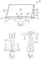
- the schematically indicated window system 10 comprises a sash 12 which, in this exemplary embodiment, is designed as a folding sash.
- the sash 12 is movably arranged relative to a frame 14, namely a frame, and is driven to move automatically via a drive device 16.
- the drive device 16 is arranged on the frame side and is coupled to the wing 12 via a so-called wing bracket 17.
- Closing edge monitoring is therefore provided, namely with monitoring of a main closing edge 18 and two adjoining secondary closing edges 19.
- a sensor device 20 is provided which is integrated in the wing bracket 17.
- Measurement signal beams 22 are shown which are aligned circumferentially around the leaf 12, namely run both along the main closing edge 18 and along the two adjoining secondary closing edges 19.
- a deflecting element 24 for the measuring signal beams 22 is provided at two opposite ends of the main closing edge 18.
- the deflecting elements 24 are mirrors.
- a splitting device for dividing the measuring signal beam 22 into partial beams and / or a combining device for combining partial beams of a measuring signal beam 22 into a combined beam is also integrated in the wing bracket 17, so that the closing edges 18, 19 of the sash 12 can be monitored by means of a single sensor device 20.
- the in Fig. 1 The measurement signal beams 22 shown are thus partial beams of the measurement signal that are generated and / or combined by splitting.
- FIG Fig. 2 An exemplary dividing device 26 is shown in FIG Fig. 2 illustrated.
- a source 28 of a measurement signal is indicated, the measurement signal being oriented in the form of a beam 30 starting from the source 28 in the direction of the splitting device 26.
- the source 28 is a transmitter element of a sensor device, namely the sensor device 20 of Fig. 1 , for emitting a probe beam.
- the source 28 can also be a part of the body of a person that emits thermal radiation that forms the measurement signal.
- the splitting device 26 is designed and arranged in such a way that the beam 30 is split into two partial beams 32.
- the partial beams 32 are oriented in opposite directions and run essentially parallel.
- the measurement signal is light and the splitting device 26 is designed as a mirror arrangement and / or as a prism.
- FIG Fig. 3 An exemplary merging device 34 is shown in FIG Fig. 3 illustrated.
- a depression 36 of a measurement signal is indicated, the measurement signal being oriented in the form of a beam 30 starting from the combining device 34 in the direction of the depression 36.
- the sink 36 is a receiver element of a sensor device, namely the sensor device 20 of FIG Fig. 1 .
- two partial beams 32 are indicated, which are aligned in the direction of the combining device 34 and are combined by this to form the beam 30, so that ultimately the measurement signal of the two partial beams 32 is guided to the depression 36 is.
- the partial beams 32 are aligned in opposite directions and run essentially parallel.
- the measurement signal is light and the combining device 34 is designed as a mirror arrangement and / or as a prism.
- the dividing devices 26 are the Fig. 2 and the combining device 34 of FIG Fig. 3 formed by one and the same device, namely by one and the same mirror arrangement and / or one and the same prism.
- the source 28 of the Fig. 2 and the depression 36 of the Fig. 3 form a transmitter element and a receiver element of the sensor device 20 and are arranged in a common sensor unit.
- a scanning beam 30 of the measurement signal is first emitted by the transmitter element, namely the source 28, and guided to the device 26, 34, which divides the scanning beam 30 into partial beams 32.
- the partial beams 32 extend over different movement areas of the wing 12. If an obstacle gets into one of the partial beams 32, the measurement signal is reflected and returns to the device 26, 34 Fig. 3 forms, to the receiver element, namely the sink 36, which detects the reflection of the probe beam as a measurement signal. It is irrelevant here that the second partial beam 32 is not also active in this situation. Rather, it is sufficient if an obstacle is detected in one of the two different movement areas.
- At least one transmitter element and at least one receiver element of the sensor device can also be arranged at a distance from one another.
- this is the case in Fig. 4 illustrated.
- a single receiver element 40 is provided, the measurement signal beams 22 being combined as partial beams by a combining device 34 and being guided to the receiver element 40.
- the measurement signal beams 22 are deflected on their respective path from the transmitter element 38 to the combining device 34 or the receiver element 40 by a deflecting element 24, in particular from a secondary closing edge 19 to a main closing edge 18.
- transmitter elements 38 and receiver element 40 shown here can alternatively also be designed the other way around, i.e. H. Receiver elements are provided at position 38 and a transmitter element is provided at position 40, with a dividing device being arranged at position 34.
- FIG. 5 An embodiment of a window system 10 is illustrated, in which two elements 42 are provided at opposite ends of the main closing edge 18, each of which comprises one or more transmitter elements, at least one receiver element and a dividing and / or combining device, such as those shown in FIGS Figs. 2 and 3 is illustrated.
- FIG. 6 An embodiment of a window system 10 is illustrated that corresponds to that of FIG Fig. 1 resembles. In contrast to this, in Fig. 6 the entire sensor arrangement arranged on the frame side.
- a combined dividing and combining device 26, 34 is also provided integrated in this drive device 16.
- the measurement signal beams 22 are aligned circumferentially around the window, with two deflection devices 24 for the deflection of the measurement signal beams 22 between the main closing edge 18 and secondary closing edge 19 being provided here as well.
- a drive device can in principle also be mounted on the sash side as an alternative to the embodiments shown here and is then coupled to a frame-side coupling device for power transmission, wherein the coupling device can be arranged at the position at which the drive device 16 is provided.
- the sensor device 20 and the dividing and / or combining device 26, 34 are then arranged integrated in the coupling device.
- a further embodiment of a window system 10 is illustrated, the sensor arrangement being that of Fig. 4 is similar, but is arranged on the frame side.
- the transmitter elements 38 are arranged at a distance from the receiver element 40, the sensing beams or measurement signal beams 22 emitted by the transmitter elements 38 being deflected by deflecting elements 24 between the closing edges.
Landscapes
- Power-Operated Mechanisms For Wings (AREA)
Applications Claiming Priority (1)
| Application Number | Priority Date | Filing Date | Title |
|---|---|---|---|
| DE102020205819.9A DE102020205819A1 (de) | 2020-05-08 | 2020-05-08 | Automatische Fenster- oder Türanlage |
Publications (1)
| Publication Number | Publication Date |
|---|---|
| EP3907366A1 true EP3907366A1 (fr) | 2021-11-10 |
Family
ID=75581434
Family Applications (1)
| Application Number | Title | Priority Date | Filing Date |
|---|---|---|---|
| EP21169084.7A Pending EP3907366A1 (fr) | 2020-05-08 | 2021-04-19 | Installation automatique de fenêtre ou de porte |
Country Status (2)
| Country | Link |
|---|---|
| EP (1) | EP3907366A1 (fr) |
| DE (1) | DE102020205819A1 (fr) |
Citations (4)
| Publication number | Priority date | Publication date | Assignee | Title |
|---|---|---|---|---|
| DE4337059A1 (de) * | 1993-10-29 | 1995-05-04 | Klemens Schlachter | Anordnung zur Notabschaltung eines motorischen Antriebes zum Schließen von Dreh- und/oder Kippfenstern |
| FR2765345A1 (fr) * | 1997-06-26 | 1998-12-31 | Memco Ltd | Detecteur d'obstruction d'une porte |
| US20160047159A1 (en) * | 2014-08-15 | 2016-02-18 | Fraba B.V. | Device for monitoring a machine movement and method for monitoring a machine movement |
| US20180292512A1 (en) * | 2017-04-10 | 2018-10-11 | Sick Ag | Optoelectronic sensor and method for detecting an object |
Family Cites Families (1)
| Publication number | Priority date | Publication date | Assignee | Title |
|---|---|---|---|---|
| US7221288B2 (en) | 2004-10-25 | 2007-05-22 | The Chamberlain Group, Inc. | Method and apparatus for using optical signal time-of-flight information to facilitate obstacle detection |
-
2020
- 2020-05-08 DE DE102020205819.9A patent/DE102020205819A1/de active Pending
-
2021
- 2021-04-19 EP EP21169084.7A patent/EP3907366A1/fr active Pending
Patent Citations (4)
| Publication number | Priority date | Publication date | Assignee | Title |
|---|---|---|---|---|
| DE4337059A1 (de) * | 1993-10-29 | 1995-05-04 | Klemens Schlachter | Anordnung zur Notabschaltung eines motorischen Antriebes zum Schließen von Dreh- und/oder Kippfenstern |
| FR2765345A1 (fr) * | 1997-06-26 | 1998-12-31 | Memco Ltd | Detecteur d'obstruction d'une porte |
| US20160047159A1 (en) * | 2014-08-15 | 2016-02-18 | Fraba B.V. | Device for monitoring a machine movement and method for monitoring a machine movement |
| US20180292512A1 (en) * | 2017-04-10 | 2018-10-11 | Sick Ag | Optoelectronic sensor and method for detecting an object |
Also Published As
| Publication number | Publication date |
|---|---|
| DE102020205819A1 (de) | 2021-11-11 |
Similar Documents
| Publication | Publication Date | Title |
|---|---|---|
| DE3689612T2 (de) | Annäherungsdetektor. | |
| EP2296002B1 (fr) | Scanner optoélectronique pour la détermination de distances en azimut et élévation | |
| EP1857983B1 (fr) | Barrière de passage avec capteur pour détecter la présence d'une personne dans le passage | |
| DE69519066T2 (de) | Aufzugsvorrichtung zur Verhinderung des vorzeitigen Verschlusses von Schiebetüren | |
| DE4435156A1 (de) | Ultraschallsensor | |
| EP2082260B1 (fr) | Procédé et système de radar pour la surveillance d'une zone à surveiller | |
| DE102004021561A1 (de) | Objekterkennungssystem für ein Kraftfahrzeug | |
| EP1788467A2 (fr) | Dispositif de protection | |
| DE102012021972A1 (de) | Detektionsvorrichtung zur Detektion eines Gegenstands in einem Detektionsbereich an einem Innenverkleidungsteil eines Kraftfahrzeugs, Kraftfahrzeug und entsprechendes Verfahren | |
| EP3581747B1 (fr) | Dispositif de surveillance | |
| EP1640742A1 (fr) | Procédé de fonctionnement d'un radar | |
| EP2818620B1 (fr) | Installation de fenêtre ou de porte automatique | |
| DE202017103676U1 (de) | Radarvorrichtung zur Erfassung eines Objekts in einem Überwachungsbereich | |
| EP2276902B1 (fr) | Procede et dispositif de commande d'une porte a deplacement vertical ou horizontal, avec securisation anti-obstacles du plan de fermeture de porte | |
| EP0236755B1 (fr) | Dispositif de détection d'une interruption dans un espace situé entre l'émetteur et le récepteur d'un signal lumineux émis d'au moins un émetteur | |
| EP3907366A1 (fr) | Installation automatique de fenêtre ou de porte | |
| EP1797459B1 (fr) | Capteur infrarouge de mesure de place de stationnement et de surveillance de champ pour un vehicule | |
| DE102020119925A1 (de) | Automatische Drehflügeltür und Sensor | |
| DE102004062370A1 (de) | Vorrichtung zur Detektion eines Objekts im Bereich eines beweglich gelagerten Karosserieteils | |
| DE102006043615A1 (de) | Verfahren und Vorrichtung zum Erkennen eines Hindernisses in einem Öffnungsbereich einer verschließbaren Öffnung | |
| EP3296178A1 (fr) | Véhicule doté d'un dispositif transducteur | |
| DE102020205814B4 (de) | Automatische Fenster- oder Türanlage | |
| AT396188B (de) | Verfahren zum ueberwachen des raumes zwischen kraftbewegten einrichtungen | |
| DE102004032048A1 (de) | Verfahren und Vorrichtung zur Bestimmung der Ausrichtung eines ersten Objektes zu einem zweiten Objekt | |
| EP2584375B1 (fr) | Capteur de surveillance de porte et procédé de surveillance de la contre-arête de fermeture d'une porte, notamment d'une porte tournante |
Legal Events
| Date | Code | Title | Description |
|---|---|---|---|
| PUAI | Public reference made under article 153(3) epc to a published international application that has entered the european phase |
Free format text: ORIGINAL CODE: 0009012 |
|
| STAA | Information on the status of an ep patent application or granted ep patent |
Free format text: STATUS: THE APPLICATION HAS BEEN PUBLISHED |
|
| AK | Designated contracting states |
Kind code of ref document: A1 Designated state(s): AL AT BE BG CH CY CZ DE DK EE ES FI FR GB GR HR HU IE IS IT LI LT LU LV MC MK MT NL NO PL PT RO RS SE SI SK SM TR |
|
| B565 | Issuance of search results under rule 164(2) epc |
Effective date: 20210928 |
|
| STAA | Information on the status of an ep patent application or granted ep patent |
Free format text: STATUS: REQUEST FOR EXAMINATION WAS MADE |
|
| 17P | Request for examination filed |
Effective date: 20220310 |
|
| RBV | Designated contracting states (corrected) |
Designated state(s): AL AT BE BG CH CY CZ DE DK EE ES FI FR GB GR HR HU IE IS IT LI LT LU LV MC MK MT NL NO PL PT RO RS SE SI SK SM TR |
|
| STAA | Information on the status of an ep patent application or granted ep patent |
Free format text: STATUS: EXAMINATION IS IN PROGRESS |
|
| 17Q | First examination report despatched |
Effective date: 20230908 |
|
| P01 | Opt-out of the competence of the unified patent court (upc) registered |
Free format text: CASE NUMBER: UPC_APP_120115/2023 Effective date: 20230510 |