EP3909660B1 - Zentrifugalentlüfter für flugzeugtriebwerk - Google Patents
Zentrifugalentlüfter für flugzeugtriebwerk Download PDFInfo
- Publication number
- EP3909660B1 EP3909660B1 EP21173769.7A EP21173769A EP3909660B1 EP 3909660 B1 EP3909660 B1 EP 3909660B1 EP 21173769 A EP21173769 A EP 21173769A EP 3909660 B1 EP3909660 B1 EP 3909660B1
- Authority
- EP
- European Patent Office
- Prior art keywords
- gap
- aerator
- aft
- housing
- oil
- Prior art date
- Legal status (The legal status is an assumption and is not a legal conclusion. Google has not performed a legal analysis and makes no representation as to the accuracy of the status listed.)
- Active
Links
Images


Classifications
-
- F—MECHANICAL ENGINEERING; LIGHTING; HEATING; WEAPONS; BLASTING
- F16—ENGINEERING ELEMENTS AND UNITS; GENERAL MEASURES FOR PRODUCING AND MAINTAINING EFFECTIVE FUNCTIONING OF MACHINES OR INSTALLATIONS; THERMAL INSULATION IN GENERAL
- F16N—LUBRICATING
- F16N39/00—Arrangements for conditioning of lubricants in the lubricating system
- F16N39/002—Arrangements for conditioning of lubricants in the lubricating system by deaeration
-
- B—PERFORMING OPERATIONS; TRANSPORTING
- B01—PHYSICAL OR CHEMICAL PROCESSES OR APPARATUS IN GENERAL
- B01D—SEPARATION
- B01D19/00—Degasification of liquids
- B01D19/0042—Degasification of liquids modifying the liquid flow
- B01D19/0052—Degasification of liquids modifying the liquid flow in rotating vessels, vessels containing movable parts or in which centrifugal movement is caused
-
- F—MECHANICAL ENGINEERING; LIGHTING; HEATING; WEAPONS; BLASTING
- F01—MACHINES OR ENGINES IN GENERAL; ENGINE PLANTS IN GENERAL; STEAM ENGINES
- F01D—NON-POSITIVE DISPLACEMENT MACHINES OR ENGINES, e.g. STEAM TURBINES
- F01D25/00—Component parts, details, or accessories, not provided for in, or of interest apart from, other groups
- F01D25/18—Lubricating arrangements
-
- F—MECHANICAL ENGINEERING; LIGHTING; HEATING; WEAPONS; BLASTING
- F01—MACHINES OR ENGINES IN GENERAL; ENGINE PLANTS IN GENERAL; STEAM ENGINES
- F01D—NON-POSITIVE DISPLACEMENT MACHINES OR ENGINES, e.g. STEAM TURBINES
- F01D25/00—Component parts, details, or accessories, not provided for in, or of interest apart from, other groups
- F01D25/18—Lubricating arrangements
- F01D25/20—Lubricating arrangements using lubrication pumps
-
- F—MECHANICAL ENGINEERING; LIGHTING; HEATING; WEAPONS; BLASTING
- F16—ENGINEERING ELEMENTS AND UNITS; GENERAL MEASURES FOR PRODUCING AND MAINTAINING EFFECTIVE FUNCTIONING OF MACHINES OR INSTALLATIONS; THERMAL INSULATION IN GENERAL
- F16N—LUBRICATING
- F16N7/00—Arrangements for supplying oil or unspecified lubricant from a stationary reservoir or the equivalent in or on the machine or member to be lubricated
- F16N7/38—Arrangements for supplying oil or unspecified lubricant from a stationary reservoir or the equivalent in or on the machine or member to be lubricated with a separate pump; Central lubrication systems
- F16N7/40—Arrangements for supplying oil or unspecified lubricant from a stationary reservoir or the equivalent in or on the machine or member to be lubricated with a separate pump; Central lubrication systems in a closed circulation system
-
- F—MECHANICAL ENGINEERING; LIGHTING; HEATING; WEAPONS; BLASTING
- F02—COMBUSTION ENGINES; HOT-GAS OR COMBUSTION-PRODUCT ENGINE PLANTS
- F02C—GAS-TURBINE PLANTS; AIR INTAKES FOR JET-PROPULSION PLANTS; CONTROLLING FUEL SUPPLY IN AIR-BREATHING JET-PROPULSION PLANTS
- F02C7/00—Features, components parts, details or accessories, not provided for in, or of interest apart form groups F02C1/00 - F02C6/00; Air intakes for jet-propulsion plants
- F02C7/32—Arrangement, mounting, or driving, of auxiliaries
-
- F—MECHANICAL ENGINEERING; LIGHTING; HEATING; WEAPONS; BLASTING
- F05—INDEXING SCHEMES RELATING TO ENGINES OR PUMPS IN VARIOUS SUBCLASSES OF CLASSES F01-F04
- F05D—INDEXING SCHEME FOR ASPECTS RELATING TO NON-POSITIVE-DISPLACEMENT MACHINES OR ENGINES, GAS-TURBINES OR JET-PROPULSION PLANTS
- F05D2220/00—Application
- F05D2220/30—Application in turbines
- F05D2220/32—Application in turbines in gas turbines
- F05D2220/323—Application in turbines in gas turbines for aircraft propulsion, e.g. jet engines
-
- F—MECHANICAL ENGINEERING; LIGHTING; HEATING; WEAPONS; BLASTING
- F05—INDEXING SCHEMES RELATING TO ENGINES OR PUMPS IN VARIOUS SUBCLASSES OF CLASSES F01-F04
- F05D—INDEXING SCHEME FOR ASPECTS RELATING TO NON-POSITIVE-DISPLACEMENT MACHINES OR ENGINES, GAS-TURBINES OR JET-PROPULSION PLANTS
- F05D2260/00—Function
- F05D2260/60—Fluid transfer
-
- F—MECHANICAL ENGINEERING; LIGHTING; HEATING; WEAPONS; BLASTING
- F05—INDEXING SCHEMES RELATING TO ENGINES OR PUMPS IN VARIOUS SUBCLASSES OF CLASSES F01-F04
- F05D—INDEXING SCHEME FOR ASPECTS RELATING TO NON-POSITIVE-DISPLACEMENT MACHINES OR ENGINES, GAS-TURBINES OR JET-PROPULSION PLANTS
- F05D2260/00—Function
- F05D2260/60—Fluid transfer
- F05D2260/602—Drainage
-
- F—MECHANICAL ENGINEERING; LIGHTING; HEATING; WEAPONS; BLASTING
- F05—INDEXING SCHEMES RELATING TO ENGINES OR PUMPS IN VARIOUS SUBCLASSES OF CLASSES F01-F04
- F05D—INDEXING SCHEME FOR ASPECTS RELATING TO NON-POSITIVE-DISPLACEMENT MACHINES OR ENGINES, GAS-TURBINES OR JET-PROPULSION PLANTS
- F05D2260/00—Function
- F05D2260/60—Fluid transfer
- F05D2260/602—Drainage
- F05D2260/6022—Drainage of leakage having past a seal
-
- F—MECHANICAL ENGINEERING; LIGHTING; HEATING; WEAPONS; BLASTING
- F05—INDEXING SCHEMES RELATING TO ENGINES OR PUMPS IN VARIOUS SUBCLASSES OF CLASSES F01-F04
- F05D—INDEXING SCHEME FOR ASPECTS RELATING TO NON-POSITIVE-DISPLACEMENT MACHINES OR ENGINES, GAS-TURBINES OR JET-PROPULSION PLANTS
- F05D2260/00—Function
- F05D2260/60—Fluid transfer
- F05D2260/609—Deoiling or demisting
-
- F—MECHANICAL ENGINEERING; LIGHTING; HEATING; WEAPONS; BLASTING
- F05—INDEXING SCHEMES RELATING TO ENGINES OR PUMPS IN VARIOUS SUBCLASSES OF CLASSES F01-F04
- F05D—INDEXING SCHEME FOR ASPECTS RELATING TO NON-POSITIVE-DISPLACEMENT MACHINES OR ENGINES, GAS-TURBINES OR JET-PROPULSION PLANTS
- F05D2260/00—Function
- F05D2260/98—Lubrication
-
- F—MECHANICAL ENGINEERING; LIGHTING; HEATING; WEAPONS; BLASTING
- F16—ENGINEERING ELEMENTS AND UNITS; GENERAL MEASURES FOR PRODUCING AND MAINTAINING EFFECTIVE FUNCTIONING OF MACHINES OR INSTALLATIONS; THERMAL INSULATION IN GENERAL
- F16N—LUBRICATING
- F16N2210/00—Applications
- F16N2210/02—Turbines
-
- F—MECHANICAL ENGINEERING; LIGHTING; HEATING; WEAPONS; BLASTING
- F16—ENGINEERING ELEMENTS AND UNITS; GENERAL MEASURES FOR PRODUCING AND MAINTAINING EFFECTIVE FUNCTIONING OF MACHINES OR INSTALLATIONS; THERMAL INSULATION IN GENERAL
- F16N—LUBRICATING
- F16N2210/00—Applications
- F16N2210/08—Aircraft
Definitions
- the disclosure relates generally to lubrication systems of aircraft engines and, more particularly, to systems and methods used to separate air from oil flowing in such lubrication systems.
- Aircraft engines such as gas turbine engines, include a lubrication system for distributing a lubricating fluid, such as oil for instance, to required portions of the engine.
- a lubricating fluid such as oil for instance
- This lubricating oil may be directed to and from a bearing cavity of the aircraft engine, for example. Air may become mixed with said oil due to the compressed air used for pressurizing the bearing cavity, and the amount of air in the lubricating oil may thus increase after the oil has been fed through the bearing cavity.
- a de-aerator may be used in the lubrication system to remove at least a portion of the air from the oil.
- EP 3 315 182 A1 discloses a prior art centrifugal separator for separating gas and liquid from a gas-liquid mixture.
- a de-aerator for a lubrication system of an aircraft engine as set forth in claim 1.
- the portion of the housing is a fore annular shoulder on an inlet side of the de-aerator, proximate the air-oil inlet, and oriented radially outwardly relative to the central axis.
- the peripheral wall of the fore opening extends axially from a fore edge to an aft edge, the fore annular shoulder of the housing extending axially beyond the aft edge of the peripheral wall.
- the hub has an aft peripheral wall oriented radially inwardly relative to the central axis and defining an aft opening communicating with the flow passages, the hub having an annular face extending radially from the aft opening to the aft shoulder, the annular face radially overlapping the housing, the gap having an aft gap inlet defined between the housing and the annular face of the hub.
- the oil outlet is defined by the housing and is radially offset from the central axis.
- the de-aerator further includes a blow conduit having a blow inlet for receiving compressed air and a blow outlet hydraulically connected to the gap between the fore gap inlet of the gap on an inlet side of the de-aerator and an aft gap inlet on an outlet side of the de-aerator.
- the de-aerator further includes a drain conduit having a drain inlet hydraulically connected to the gap between the fore gap inlet and an aft gap inlet, and a drain outlet hydraulically connected to the air-oil inlet and/or to the air outlet of the de-aerator.
- the flow passages have passage inlets having a radial component oriented away from the central axis, and the gap at the fore gap inlet facing a direction being mainly axial relative to the central axis.
- the flow passages have passage outlets having a radial component oriented toward the central axis, the gap having and an aft gap inlet on an outlet side of the de-aerator, the aft gap inlet having a radial component extending away from the central axis.
- the rotor includes an aft annular flange extending circumferentially around the central axis, a portion of the blades curving around a radially outer edge of the aft annular flange, the passage outlets defined axially between the hub and the aft annular flange and circumferentially between the blades.
- the rotor has a shaft rotatably received within the housing, the hub of the rotor defining a fore opening leading to the flow passages and radially between the hub and the shaft, a portion of the housing received within the fore opening, the fore gap inlet defined between the hub at the fore opening and the portion of the housing.
- Fig. 1 illustrates an aircraft engine 10, such as a gas turbine engine, of a type preferably provided for use in subsonic flight.
- the gas turbine engine 10 generally includes in serial flow communication a fan 12 through which ambient air is propelled, a compressor section 14 for pressurizing the air, a combustor 16 in which the compressed air is mixed with fuel and ignited for generating an annular stream of hot combustion gases, and a turbine section 18 for extracting energy from the combustion gases.
- the fan 12, the compressor section 14, and the turbine section 18 are rotatable about a central axis 11 of the gas turbine engine 10.
- the gas turbine engine 10 includes a lubrication system 100 that includes a pump 102, lubrication conduits 104, a lubricant reservoir 106, and a de-aerator 30.
- the lubrication system 100 may also include additional components such as valve(s), heat exchangers, filters, etc.
- the lubricant reservoir 106 is hydraulically connected to one or more components C of the engine 10 in need of lubrication, such as, for instance, bearing cavity(ies) 13, gearbox(es), and so on.
- the pump 102 is operable to induce a flow of the lubricant from the lubricant reservoir 106, to the one or more components C of the engine 10 in need of lubrication, and a scavenge pump 108 operable to draw a scavenge flow of oil back to the reservoir 106.
- the scavenge pump 108 has an inlet hydraulically connected to a scavenge outlet C1 of the component C and an outlet hydraulically connected to the de-aerator 30. In some cases, for instance when the component C is a bearing cavity 13 , the oil flows through the bearing cavity 13 and is mixed with compressed air injected therein for pressurizing the bearing cavity 13.
- the oil mixture exiting the bearing cavity 13 may thus have a greater air content than the oil mixture entering the bearing cavity 13.
- the de-aerator 30 is operable to remove at least a portion of the air contained within the air-oil mixture it receives before flowing the oil back to the one or more components in need of lubrication.
- the de-aerator 30 has an air-oil inlet 30a hydraulically connected to the scavenge outlet C1 of the component C via the scavenge pump 108; an oil outlet 30b hydraulically connected to the reservoir 106 for returning the de-aerated oil back to the reservoir 106 from which it is drawn by the pump 102 for lubrication purposes; and an air outlet 30c hydraulically connected to a vent 110 for expelling the air out to an environment E outside the gas turbine engine 10.
- the location of some of the parts of the lubrication system 100 e.g., scavenge pump 108, pump 102, vent 110
- the de-aerator 30 may be included in any suitable lubrication system.
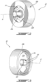
- the de-aerator 30 includes a rotor 32, also referred to as an impeller, and a stator, also referred to as a housing 34 ( Fig. 6 ).
- the rotor 32 is received within the housing 34 and rotates relative to the housing 34 about a central axis A.
- the de-aerator 30 has an inlet side I and an opposed outlet side O.
- the air-oil inlet 30a of the de-aerator 30 is located on the inlet side I.
- the oil outlet 30b and the air outlet 30c of the de-aerator 30 are located on the outlet side O of the de-aerator 30.
- the air-oil inlet 30a, the oil outlet 30b, and the air outlet 30c are defined by the housing 34.
- the rotor 32 has a shaft 32a that is drivingly engageable for receiving a rotational input.
- the rotational input may be provided by an electric motor, a shaft of the gas turbine engine 10 ( Fig. 1 ), or any device able to generate a rotational input to the rotor 32.
- the rotor 32 has a hub 32b and blades 32c that are circumferentially distributed around the central axis A.
- the hub 32b extends circumferentially all around the central axis A and around the blades 32c.
- the blades 32c are secured to a fore flange 32d that is secured to the shaft 32a and to an aft flange 32e.
- Both of the first and second flanges 32d, 32e are annular and extend all around the central axis A.
- the fore flange 32d is secured to the shaft 32a via a fillet.
- the fore flange 32d is used to redirect a flow of oil that enters the de-aerator 30 in a substantially axial direction relative to the central axis A to a substantially radial direction relative to the central axis A before said flow of oil meets the blades 32c.
- the blades 32c have radially inner ends 32f and radially outer ends 32g. In the embodiment shown, the radially outer ends 32g of the blades 32c are secured to the hub 32b of the rotor 32.
- fillets are located at junctions between the blades 32c and the hub 32b.
- the radially inner ends 32f of the blades 32c are located axially between the fore and aft flanges 32d, 32e.
- a plurality of flow passages P are defined circumferentially between each two circumferentially adjacent ones of the blades 32c.
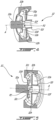
- the flow passages P have passage inlets P1 ( Fig. 2 ) extending radially between a periphery of the first flange 32d and the hub 32b, extending circumferentially between each two adjacent ones of the blades 32c, and extending axially between the hub 32b and the fore flange 32d.
- the inlets P1 of the flow passages P face a direction which has a radial component relative to the central axis A.
- the radial component of the inlets P1 of the flow passages P is oriented away from the central axis A.
- the flow passages P have air outlets P2 ( Figs. 5-6 ) proximate the central axis A.
- the air outlets P2 of the flow passages P are defined circumferentially between each of two adjacent ones of the radially inner ends 32f of the blades 32c and axially between the fore and aft flanges 32d, 32e.
- the flow passages P further have oil outlets P3 ( Fig. 3 ) located axially between the hub 32b and the aft flange 32e and circumferentially between the blades 32c. More specifically, a portion 32c1 ( Figs. 6 ) of the blades 32c curves around the radially outer edge 32h ( Figs. 4-5 ) of the aft annular flange 32e.
- the oil outlets P3 are defined by the portion of the blades 32c that curve around the aft annular flange 32e.
- the portions 32c1 of the blades 32c that extend around the aft flange 32e have radially inner ends 32c2 ( Fig. 6 ).
- the oil outlets P3 are defined circumferentially between each two adjacent ones of the radially inner ends 32c2 of the portions 32c1 of the blades 32c.
- the rotor 32 further has a hollow tube 32i secured to the second flange 32e. As illustrated more clearly in Fig. 6 , the hollow tube 32i is rotatably received within a bore 34a of the housing 34. It will be appreciated that a bearing may be disposed between the bore 34a of the housing 34 and the hollow tube 32i.
- the hollow tube 32i has an internal passage P4 that is fluidly connected to the air outlets P2 of the flow passages P defined between the blades 32c of the rotor 32.
- the internal passage P4 defined by the hollow tube 32i may be hydraulically connected to the vent 110 ( Fig. 1a ) of the lubrication system 100 ( Fig. 1 ) via suitable conduits for expelling the extracted air out of the lubrication system 100.
- an air-oil mixture is received into the de-aerator 30 via the air-oil inlet 30a along arrow A1.
- the oil is diverted radially outwardly away from the central axis A by the fore flange 32d.
- the oil is then divided between the flow passages P upon rotation of the fore flange 32d and enters those flow passages P via their respective inlets P1 ( Fig. 2 ).
- the oil is then impinged by the blades 32c of the rotor 32. Such impingement may cause separation of the air contained in the air-oil mixture from the oil.
- the separated oil flows within the flow passages P defined between the blades 32c, around the periphery 32h of the second flange 32e along arrow A2 ( Fig. 6 ) and exits the flow passages P via the oil outlet P3 ( Fig. 3 ) defined axially between the aft flange 32e and the hub 32b and circumferentially between the radially-inner ends 32c2 of the portions 32c1 of the blades 32c that extend aft of the aft flange 32e.
- the oil then exits the de-aerator 30 via the oil outlet 30b thereof along arrow A3. As shown in Fig.
- the extracted oil is then flown back to the reservoir 106 via which it is circulated to the components (e.g., bearing cavity 13) in need of lubrication.
- the air extracted from the air-oil mixture flows around a periphery of the first flange 32d along arrow A4, moves radially inwardly toward the central axis A, and exits the flow passages P via their air outlets P2 defined circumferentially between the radially-inner ends 32f of the portions of the blades 32c that are located between the fore and aft flanges 32d, 32e.
- the extracted air then flows into the passage P4 of the hollow tube 32i along arrow A5 and out of the de-aerator 30 via the bore 34a of the housing 34 and via the air outlet 30c of the de-aerator 30.
- the disclosed de-aerator 30 has solely two outlets: the oil outlet 30b and the air outlet 30c.
- the de-aerator 30 has solely three connections to the oil system 100 ( Fig. 1a ), that is the air-oil inlet 30a, the air outlet 30c, and the oil outlet 30b, and is free of other connections to the oil system 100.
- the de-aerator 30 is an "active" de-aerator since it has at least one component (e.g., rotor 32) that is driven, such as by electrical and/or pneumatic and/or hydraulic or other means (motors, actuators, etc.).
- a de-aerator is different than a de-oiler.
- a de-oiler is typically located within a lubricated cavity (e.g., gear box) and is designed to remove oil (e.g., oil droplets/mist) within an air-oil mixture before ejecting air overboard.
- the de-aerator 30 is designed to extract air from an air-oil mixture and to feed oil back to the oil system 100.
- the de-oiler does not include a housing and is therefore not subjected to problems associated with oil trapped in a gap. Indeed, the housing of the de-aerator 30 is used to collect the oil extracted by centrifugation so that said extracted oil is flown back to the oil system.
- the de-oiler Since the de-oiler is located within the lubricated cavity, it does not need a housing and the oil may simply be ejected via centrifugation against the components in need of lubrication contained within the lubricated cavity (e.g., gears).
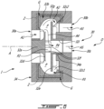
- a gap G is present between the rotor 32 and the housing 34.
- the gap G extends circumferentially all around the central axis A. It has been observed that, in some cases, oil may become trapped within the gap G. More specifically, as the oil is centrifuged by the rotor 32, a portion may flow into the gap G and may remain trapped because of the centrifugal effect. Oil may therefore be located within the gap G and all around the rotor 32 by centrifugal effect. The portion Z where oil may be trapped is shown with dashed lines in Fig. 6 . In some cases, the trapped oil can generate heat as it is sheared between the rotor 32 and the housing 34.
- Figs. 7-10 described below explain features that the de-aerator 30 may have to limit oil from being trapped in the gap G.
- the housing 34 has a fore annular shoulder 34b on the inlet side I of the de-aerator 30 and proximate the air-oil inlet 30a of the de-aerator 30.
- the fore annular shoulder 34b are herein oriented radially outwardly relative to the central axis A and faces the hub 32b.
- the hub 32b defines a fore opening 32j that leads into the flow passages P between the blades 32c of the rotor 32.
- the fore opening 32j of the hub 32 is defined by a substantially cylindrical peripheral wall 32j3 extending circumferentially around the central axis A and extending axially from a fore edge 32j 1 to an aft edge 32j2 aft of the fore edge 32j 1.
- a portion of the housing 34 overlaps the fore opening 32j of the hub 32.
- a portion of the housing 34 which herein may correspond to the fore annular shoulder 34b of the housing 34, is received within the fore opening 32j and overlaps the peripheral wall 32j3 of the fore opening 32j of the hub 32.
- the fore annular shoulder 34b of the housing 34 extends axially beyond the aft edge 32j2 of the fore opening 32j of the hub 32b.
- the gap G has a fore gap inlet G1 (dashed lines in Fig. 7a ) between the hub 32b and the housing 34.
- the overlap between the fore annular shoulder 34b of the housing 34 and the fore opening 32j of the hub 32b is such that the fore gap inlet G1 has a radial component relative to the central axis A and that said radial component of the fore gap inlet G1 extends toward the central axis A.
- the fore gap inlet G1 extends circumferentially all around the central axis A, radially from the aft edge 32j2 of the peripheral wall 32j3 to an edge 34b1 of the fore annular shoulder 34b of the housing 34, and axially from said aft edge 32j2 of the peripheral wall 32j3 to the edge 34b1 of the fore annular shoulder 34b.
- the edge 34b1 of the fore annular shoulder 34b and the aft edge 32j2 of the peripheral wall 32j3 are axially offset from one another.
- such an overlap between the hub 32b and the housing 34 may shield the fore gap inlet G1 from a flow F1 extending in a substantial radial direction relative to the central axis A and that is directed toward the inlets P1 of the flow passages P between the blades 32c of the rotor 32.
- a flow F1 extending in a substantial radial direction relative to the central axis A and that is directed toward the inlets P1 of the flow passages P between the blades 32c of the rotor 32.
- For oil to enter into the gap G it has to flow in a direction having a radial component that is in an opposite direction to a radial component of the flow F1 that is directed toward the flow passages P.
- This overlap may require the oil to change its direction to enter the gap G.
- the gap G at the fore gap inlet G1 faces a direction D1 that is mainly axial relative to the central axis 11. This difference between the direction D1 of the gap G at the fore gap inlet G1 and the direction of the flow F1 may make it more difficult for the oil to reach the gap G. This may limit a quantity of oil trapped within the gap G compared to a configuration lacking such an overlap.
- the overlap of the housing 34 and rotor 32 may make it more difficult for the oil to go through a path depicted by arrow A6 rather than a path depicted by arrow A7.
- the hub 32b has an aft annular shoulder 32k that is oriented radially inwardly toward the central axis A and that faces an aft annular shoulder 34c of the housing 34.
- the aft annular shoulder 34c of the housing 34 is oriented radially away from the central axis A.
- the aft annular shoulder 34c of the housing 34 axially overlaps the aft annular shoulder 32k of the hub 32b of the rotor 32.
- the hub 32b defines an aft opening 32l and has an annular face 32m extending radially relative to the central axis A from the aft opening 32l to the aft shoulder 32k.
- An aft gap inlet G2 (dashed line in Fig. 7b ) of the gap G is located axially between the housing 34 and the annular face 32m of the hub 32b of the rotor 32.
- the gap G at the aft gap inlet G2 faces a direction D2 that is mainly radial relative to the central axis 11. This similarity between the direction D2 of the gap G at the aft gap inlet G2 and the direction of a flow F2 between the blades 32c may make it more difficult for the oil to reach the gap G.
- the disclosed geometry may create a complex path depicted by arrow A8 and it may be easier for the oil to go through a path depicted by arrow A9 instead.
- the oil curves around the outer edge 32h ( Fig. 5 ) of the aft flange 32e ( Fig. 5 ) along the arrow A2. Then, a flow of oil F2 ( Fig. 7 ) flows in a direction being substantially radial toward the central axis A and toward the passage outlets P3 ( Fig. 3 ).
- the aft gap inlet G2 has a radial component that extends away from the central axis A.
- a tortuous flow path T may increase a resistance of the flow within the gap G and may contribute in limiting oil from flowing within the gap G. This may limit a quantity of oil trapped within the gap G compared to a configuration lacking such an overlap.
- the oil outlet 30b of the de-aerator 30 includes a bore 34d defined by the housing 34; the bore 34d is herein located at an upper halve of the housing 34 and radially offset from the central axis A. Other locations of the bore 34d are contemplated. As shown in Fig. 7 , a peripheral wall 34e of the bore 34 is radially aligned with a top portion of the aft opening 32l ( Fig. 7b ) of the hub 32b.
- a de-aerator in accordance with another embodiment is shown generally at 130.
- elements that differ from the de-aerator 30 described above with reference to Figs. 2-7 are described herein below.
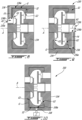
- the housing 134 of the de-aerator 130 defines a drain conduit 136.
- the drain conduit 136 has a drain inlet 136a that is hydraulically connected to the gap G between the fore gap inlet G1 and the aft gap inlet G2.
- the drain conduit 136 has a drain outlet 136b that is hydraulically connected to the air-oil inlet 130a of the de-aerator 130.
- the drain conduit 136 is located at an upper halve of the housing 134.
- the drain conduit 136 may be located anywhere along a circumference of the housing 134.
- the flow of the air-oil mixture along arrow A1 may create a pressure drop within the drain conduit 136 that may induce a flow F3 within the drain conduit 136 for suctioning the oil trapped in the gap G from the drain inlet 136a to the drain outlet 136b.
- the flow F3 is influenced at least partially by the centrifugal force exerted to the oil via rotation of the rotor 32.
- the oil extracted from the gap G may be redirected into the fluid passages P of the rotor 32 for separation.
- a de-aerator in accordance with another embodiment is shown generally at 230.
- a de-aerator in accordance with another embodiment is shown generally at 230.
- elements that differ from the de-aerator 30 described above with reference to Figs. 2-7 are described herein below.
- the housing 234 of the de-aerator 230 defines a drain conduit 236.
- the drain conduit 236 has a drain inlet 236a that is hydraulically connected to the gap G between the fore gap inlet G1 and the aft gap inlet G2.
- the drain conduit 236 has a drain outlet 236b that is hydraulically connected to the air outlet 230c of the de-aerator 230.
- the drain conduit 236 is located at a lower halve of the housing 234.
- the drain conduit 236 may be located anywhere along a circumference of the housing 234.
- the flow of the air along arrow A5 via the air outlet 230c may create a pressure drop within the drain conduit 236 that may induce a flow F4 within the drain conduit 236 for suctioning the oil trapped in the gap G form the drain inlet 236a to the drain outlet 236b.
- the flow F4 is influenced at least partially by the centrifugal force exerted to the oil via rotation of the rotor 32.
- a de-aerator in accordance with another embodiment is shown generally at 330.
- a de-aerator in accordance with another embodiment is shown generally at 330.
- elements that differ from the de-aerator 30 described above with reference to Figs. 2-7 are described herein below.
- the de-aerator 300 has a blow conduit 338 that is located at a lower halve of the housing 334.
- the blow conduit 338 may be located anywhere along a circumference of the housing 334.
- the blow conduit 338 is herein defined by the housing 334.
- the blow conduit 338 may be fluidly connected to a source of compressed air C and may have an outlet 338a hydraulically connected to the gap G between the fore gap inlet G1 and the aft gap inlet G2.
- the source of compressed air C may be, for instance, the compressor section 14 of the gas turbine engine 10 ( Fig. 1 ).
- Blowing the air within the gap G may prevent the oil from penetrating into the gap G since said oil would have to overcome the airflow exiting the gap G via the fore and aft gap inlets G1, G2.
- the blow outlet 338a may be located between the drain inlet 236a and the fore gap inlet G1.
- combining the features of the complex flow path and overlap described above with reference to Figs. 7, 7a, 7b with one or both of the drain conduits 136, 236 described above with reference to Figs. 8 and 9 may limit the amount of oil trapped between the rotor 32 and the housing 34, 134, 234. Indeed, if some oil manages to get trapped within the gap G, it may be drained out of the gap G via the drain conduits 136, 236. In a particular embodiment, combining the features of the drain conduits 136, 236 described above with reference to Figs. 8 and 9 with the blow conduit 338 described above with reference to Fig.
- blow conduit 338 described above with reference to Fig. 10 may be combined with the complex flow path and overlap described above with reference to Figs. 7, 7a, and 7b on the outlet side O of the de-aerator 30 to ensure that the air blown may not be mixed with the oil on the oil outlet 30b of the de-aerator 30. It will be appreciated that the features described above with reference to Figs. 8 to 10 may be combined with the de-aerator 30 of Fig. 7 . Any combinations of those features are contemplated without departing from the scope of the present disclosure.
- the air-oil mixture is received via the air-oil inlet 30a of the de-aerator 30 in an axial direction relative to a central axis A of the rotor 32; the received air-oil flow is redirected in a radial direction relative to the central axis A and the air is separated from the air-oil flow by centrifugation within the rotor 32; and the oil is limited from flowing within the gap G between the rotor 32 and the housing 34 by having the inlet of the gap G facing a direction different than a flow direction of the air-oil flow.
- compressed air is injected into the gap G and/or the oil is drained out from the gap.
Landscapes
- Engineering & Computer Science (AREA)
- General Engineering & Computer Science (AREA)
- Mechanical Engineering (AREA)
- Chemical & Material Sciences (AREA)
- Chemical Kinetics & Catalysis (AREA)
- Lubrication Details And Ventilation Of Internal Combustion Engines (AREA)
Claims (12)
- Entlüfter (30, 130, 230, 330) für ein Schmiersystem (100) eines Flugzeugtriebwerks (10), umfassend:ein Gehäuse (34), das einen Luft-Öl-Einlass (30a, 130a), einen Ölauslass (30b) und einen Luftauslass (30c, 130c, 230c) des Entlüfters (30, 130, 230, 330) definiert;einen Rotor (32), der innerhalb des Gehäuses (34) aufgenommen und relativ zu dem Gehäuse (34) um eine Mittelachse (A) drehbar ist, wobei der Rotor Schaufeln (32c) aufweist, die in Umfangsrichtung um die Mittelachse (A) verteilt sind und sich mindestens teilweise radial relativ zu der Mittelachse (A) erstrecken, wobei sich Strömungskanäle (P) zwischen den Schaufeln (32c) erstrecken, wobei der Rotor (32) eine Nabe (32b) aufweist, die sich in Umfangsrichtung um die Mittelachse (A) und um die Schaufeln (32c) erstreckt, wobei die Nabe (32b) eine Umfangswand (32j2) aufweist, die radial nach innen ausgerichtet ist und eine vordere Öffnung (32j) definiert, die zu den Strömungskanälen (P) führt; undeinen Spalt (G) zwischen dem Gehäuse (34) und der Nabe (32b) des Rotors (32), wobei ein Abschnitt des Gehäuses innerhalb der vorderen Öffnung (32j) aufgenommen ist und die Umfangswand (32j3) der Nabe (32b) axial überlappt, wobei der Spalt (G) einen vorderen Spalteinlass (G1) zwischen dem Abschnitt des Gehäuses und der Umfangswand (32j3) der Nabe (32b) aufweist, wobei das Gehäuse (34) eine hintere ringförmige Schulter (32k) definiert, die sich auf einer Auslassseite (O) des Entlüfters (30, 130, 230, 330) befindet und radial nach außen relativ zu der Mittelachse (A) ausgerichtet ist, wobei die hintere ringförmige Schulter (32k) eine hintere Schulter (32k) der Nabe (32b) axial überlappt und dieser zugewandt ist.
- Entlüfter (30, 130, 230, 330) nach Anspruch 1, wobei der Abschnitt des Gehäuses (34) eine vordere ringförmige Schulter (34b) auf einer Einlassseite (I) des Entlüfters (30, 130, 230, 330) ist, die sich in der Nähe des Luft-Öl-Einlasses (30a, 130a) befindet und radial nach außen relativ zu der Mittelachse (A) ausgerichtet ist.
- Entlüfter (30, 130, 230, 330) nach Anspruch 2, wobei sich die Umfangswand (32j3) der vorderen Öffnung (32j) axial von einer Vorderkante (32j1) zu einer Hinterkante (32j2) erstreckt, wobei sich die vordere ringförmige Schulter (34b) des Gehäuses (34) axial über die Hinterkante (32j2) der Umfangswand (32j3) hinaus erstreckt.
- Entlüfter (30, 130, 230, 330) nach einem der vorhergehenden Ansprüche, wobei die Nabe (32b) eine hintere Umfangswand aufweist, die radial nach innen relativ zu der Mittelachse (A) ausgerichtet ist und eine hintere Öffnung (321) definiert, die mit den Strömungskanälen (P) kommuniziert, wobei die Nabe (32b) eine ringförmige Fläche (32m) aufweist, die sich radial von der hinteren Öffnung (321) zu der hinteren Schulter (32k) erstreckt, wobei die ringförmige Fläche (32m) das Gehäuse radial überlappt, wobei der Spalt einen hinteren Spalteinlass (G2) aufweist, der zwischen dem Gehäuse (34) und der ringförmigen Fläche (32m) der Nabe (32b) definiert ist.
- Entlüfter (30, 130, 230, 330) nach einem der vorhergehenden Ansprüche, wobei der Ölauslass (30b) durch das Gehäuse (34) definiert ist und radial von der Mittelachse (A) versetzt ist.
- Entlüfter (330) nach einem der vorhergehenden Ansprüche, ferner umfassend eine Blasleitung (338), die einen Blaseinlass zum Aufnehmen von Druckluft (C) und einen Blasauslass (338a) aufweist, der hydraulisch mit dem Spalt (G) zwischen dem vorderen Spalteinlass (G1) des Spalts auf einer Einlassseite (I) des Entlüfters (300) und einem hinteren Spalteinlass (G2) auf einer Auslassseite (O) des Entlüfters (330) verbunden ist.
- Entlüfter (130, 230) nach einem der vorhergehenden Ansprüche, ferner umfassend eine Abflussleitung (136, 236), die einen Abflusseinlass, der hydraulisch mit dem Spalt (G) zwischen dem vorderen Spalteinlass (G1) und einem hinteren Spalteinlass (G2) verbunden ist, und einen Ablaufauslass (136b, 236b) aufweist, der hydraulisch mit dem Luft-Öl-Einlass (130a) und/oder mit dem Luftauslass (230c) des Entlüfters (230) verbunden ist.
- Entlüfter (30, 130, 230, 330) nach einem der vorhergehenden Ansprüche, wobei die Strömungskanäle (P) Kanaleinlässe (P1) aufweisen, die eine radiale Komponente aufweisen, welche von der Mittelachse (A) weg ausgerichtet ist, und wobei der Spalt (G) an dem vorderen Spalteinlass (G1) in eine Richtung gewandt ist, die hauptsächlich axial relativ zu der Mittelachse (A) verläuft.
- Entlüfter (30, 130, 230, 330) nach einem der vorhergehenden Ansprüche, wobei die Strömungskanäle (P) Kanalauslässe (P2) aufweisen, die eine radiale Komponente aufweisen, welche in Richtung der Mittelachse (A) ausgerichtet ist, wobei der Spalt (G) einen hinteren Spalteinlass (G2) auf einer Auslassseite (O) des Entlüfters (30, 130, 230, 330) aufweist, wobei der hintere Spalteinlass (G2) eine radiale Komponente aufweist, die sich von der Mittelachse (A) weg erstreckt.
- Entlüfter (30, 130, 230, 330) nach Anspruch 9, wobei der Rotor (32) einen hinteren ringförmigen Flansch (32e) aufweist, der sich in Umfangsrichtung um die Mittelachse (A) erstreckt, wobei ein Abschnitt der Schaufeln (32c) um eine radial äußere Kante (32h) des hinteren ringförmigen Flansches (32e) (32e) gekrümmt ist, wobei die Kanalauslässe (P2) axial zwischen der Nabe (34) und dem hinteren ringförmigen Flansch (32e) und in Umfangsrichtung zwischen den Schaufeln (32c) definiert sind.
- Entlüfter (30, 130, 230, 330) nach einem der vorhergehenden Ansprüche, wobei der Rotor (32) eine Welle (32a) aufweist, die drehbar innerhalb des Gehäuses (34) aufgenommen ist, wobei die Nabe (32b) des Rotors eine vordere Öffnung (32j) definiert, die zu den Strömungskanälen (P) führt und sich radial zwischen der Nabe (32b) und der Welle (32a) befindet, wobei ein Abschnitt des Gehäuses (34) innerhalb der vorderen Öffnung (32j) aufgenommen ist, wobei der vordere Spalteinlass (G1) zwischen der Nabe (32b) an der vorderen Öffnung (32j) und dem Abschnitt des Gehäuses (34) definiert ist.
- Verfahren zum Trennen von Luft aus einem Luft-Öl-Strom mit einem Entlüfter (30, 130, 230, 330), der einen Rotor (32) aufweist, welcher drehbar innerhalb eines Gehäuses (34) aufgenommen ist, umfassend:Aufnehmen des Luft-Öl-Stroms über einen Luft-Öl-Einlass (30a, 130a) des Entlüfters (30, 130, 230, 330) in einer axialen Richtung relativ zu einer Mittelachse (A) des Rotors (32);Umleiten des aufgenommenen Luft-Öl-Stroms in einer radialen Richtung relativ zu der Mittelachse (A) und Trennen der Luft aus dem Luft-Öl-Strom durch Zentrifugation innerhalb des Rotors (32);Begrenzen des Ölstroms innerhalb eines Spalts (G) zwischen dem Rotor (32) und dem Gehäuse (34), indem ein Einlass des Spalts (G) in eine andere Richtung als die Strömungsrichtung des Luft-Öl-Stroms gewandt ist; undEinblasen von Druckluft in den Spalt (G) und/oder Ablassen des Öls aus dem Spalt (G).
Applications Claiming Priority (1)
| Application Number | Priority Date | Filing Date | Title |
|---|---|---|---|
| US15/931,032 US11994257B2 (en) | 2020-05-13 | 2020-05-13 | Centrifugal de-aerator for aircraft engine |
Publications (2)
| Publication Number | Publication Date |
|---|---|
| EP3909660A1 EP3909660A1 (de) | 2021-11-17 |
| EP3909660B1 true EP3909660B1 (de) | 2024-04-24 |
Family
ID=75919258
Family Applications (1)
| Application Number | Title | Priority Date | Filing Date |
|---|---|---|---|
| EP21173769.7A Active EP3909660B1 (de) | 2020-05-13 | 2021-05-13 | Zentrifugalentlüfter für flugzeugtriebwerk |
Country Status (3)
| Country | Link |
|---|---|
| US (1) | US11994257B2 (de) |
| EP (1) | EP3909660B1 (de) |
| CA (1) | CA3117555A1 (de) |
Families Citing this family (6)
| Publication number | Priority date | Publication date | Assignee | Title |
|---|---|---|---|---|
| US12017157B2 (en) | 2021-01-22 | 2024-06-25 | Pratt & Whitney Canada Corp. | Deaerator for aircraft engine and associated method of operation |
| US11674406B2 (en) * | 2021-08-06 | 2023-06-13 | Pratt & Whitney Canada Corp. | Variable gap between impeller rotor and static structure |
| CN114307259B (zh) * | 2021-12-30 | 2023-05-30 | 中国航空工业集团公司金城南京机电液压工程研究中心 | 一种液力式组合传动发电机的泵式油气分离器 |
| US12330089B2 (en) | 2022-09-09 | 2025-06-17 | Pratt & Whitney Canada Corp. | Dynamic deaeration system |
| US11867357B1 (en) * | 2022-09-09 | 2024-01-09 | Pratt & Whitney Canada Corp. | Deaeration conduit |
| US12577912B1 (en) * | 2025-02-21 | 2026-03-17 | Pratt & Whitney Canada Corp. | Active de-aerator for aircraft power plant |
Family Cites Families (10)
| Publication number | Priority date | Publication date | Assignee | Title |
|---|---|---|---|---|
| DE749024C (de) | 1942-05-23 | 1952-09-04 | Daimler Benz Ag | OElentschaeumer fuer Brennkraftmaschinen, insbesondere Flugmotoren |
| DE1114437B (de) | 1960-03-07 | 1961-09-28 | Entwicklungsbau Pirna Veb | Zentrifuge zum Abscheiden von Luft und kleinen festen Bestandteilen aus Fluessigkeiten, insbesondere aus OEl |
| DE3535107A1 (de) | 1985-10-02 | 1987-04-09 | Mtu Muenchen Gmbh | Versorgungssystem von lagern |
| US5114446A (en) | 1991-02-15 | 1992-05-19 | United Technologies Corporation | Deoiler for jet engine |
| EP2199614B1 (de) | 2008-12-22 | 2016-09-28 | Safran Aero Boosters SA | Kombinierte Pump- und Abscheidemaschine für Ölkreislauf eines Turbostrahltriebwerks |
| CA2920482A1 (en) | 2013-08-16 | 2015-02-19 | General Electric Company | Flow vortex spoiler |
| ITFI20130204A1 (it) * | 2013-09-03 | 2015-03-04 | Nuovo Pignone Srl | "fan-cooled electrical machine with axial thrust compensation" |
| CN107073483B (zh) | 2014-09-25 | 2019-05-28 | 东京滤器株式会社 | 油分离器 |
| EP3315182A1 (de) | 2016-10-31 | 2018-05-02 | Pratt & Whitney Canada Corp. | Zentrifugalabscheider |
| US10870079B2 (en) | 2018-04-10 | 2020-12-22 | Pratt & Whitney Canada Corp. | Air-oil separator with first separator radially outward of matrix separator |
-
2020
- 2020-05-13 US US15/931,032 patent/US11994257B2/en active Active
-
2021
- 2021-05-06 CA CA3117555A patent/CA3117555A1/en active Pending
- 2021-05-13 EP EP21173769.7A patent/EP3909660B1/de active Active
Also Published As
| Publication number | Publication date |
|---|---|
| CA3117555A1 (en) | 2021-11-13 |
| US11994257B2 (en) | 2024-05-28 |
| US20210356077A1 (en) | 2021-11-18 |
| EP3909660A1 (de) | 2021-11-17 |
Similar Documents
| Publication | Publication Date | Title |
|---|---|---|
| EP3909660B1 (de) | Zentrifugalentlüfter für flugzeugtriebwerk | |
| US7935164B2 (en) | Vortex air-oil separator system | |
| US10729992B2 (en) | Centrifugal separator | |
| US9915176B2 (en) | Shroud assembly for turbine engine | |
| EP3943715B1 (de) | Aktive entlüftungsvorrichtung für einen flugzeugmotor | |
| US8443843B2 (en) | Air-oil separator | |
| EP1544417B1 (de) | Schmiermittelabfuhrsystem eines Gasturbinentriebwerks und Verfahren zur Schmiermittelabfuhr | |
| US10975731B2 (en) | Turbine engine, components, and methods of cooling same | |
| US20160045923A1 (en) | Inertial separator | |
| US11181010B2 (en) | Aircraft engine and air-oil separator system therefore | |
| EP3425161B1 (de) | Motorölwanne mit lufttrennungsfunktionen | |
| EP3239480B1 (de) | Schmierölrücklaufsystem für einen turbinenmotor mit gegenläufigen wellen | |
| EP4137678B1 (de) | Systeme und verfahren zur schmierung einer innenverzahnung | |
| CA3107722A1 (en) | Oil distribution system for gas turbine engine | |
| CN109630213A (zh) | 由涡轮机中的轴承支座和转子轴的轴承组成的组件 | |
| EP4293202A1 (de) | Abblasventil mit luft-öl-trennung | |
| CA2949547A1 (en) | Turbine engine and particle separators therefore | |
| US10918989B2 (en) | Air-oil separator with two flow paths | |
| EP4495393B1 (de) | Gasturbinenmotorölschaufel mit luftabscheider | |
| EP2798228B1 (de) | Strömungsmischungsvorrichtung und Verfahren zum Mischen dieser Strömungen |
Legal Events
| Date | Code | Title | Description |
|---|---|---|---|
| PUAI | Public reference made under article 153(3) epc to a published international application that has entered the european phase |
Free format text: ORIGINAL CODE: 0009012 |
|
| STAA | Information on the status of an ep patent application or granted ep patent |
Free format text: STATUS: THE APPLICATION HAS BEEN PUBLISHED |
|
| AK | Designated contracting states |
Kind code of ref document: A1 Designated state(s): AL AT BE BG CH CY CZ DE DK EE ES FI FR GB GR HR HU IE IS IT LI LT LU LV MC MK MT NL NO PL PT RO RS SE SI SK SM TR |
|
| B565 | Issuance of search results under rule 164(2) epc |
Effective date: 20211001 |
|
| STAA | Information on the status of an ep patent application or granted ep patent |
Free format text: STATUS: REQUEST FOR EXAMINATION WAS MADE |
|
| 17P | Request for examination filed |
Effective date: 20220318 |
|
| RBV | Designated contracting states (corrected) |
Designated state(s): AL AT BE BG CH CY CZ DE DK EE ES FI FR GB GR HR HU IE IS IT LI LT LU LV MC MK MT NL NO PL PT RO RS SE SI SK SM TR |
|
| GRAP | Despatch of communication of intention to grant a patent |
Free format text: ORIGINAL CODE: EPIDOSNIGR1 |
|
| STAA | Information on the status of an ep patent application or granted ep patent |
Free format text: STATUS: GRANT OF PATENT IS INTENDED |
|
| INTG | Intention to grant announced |
Effective date: 20231117 |
|
| GRAS | Grant fee paid |
Free format text: ORIGINAL CODE: EPIDOSNIGR3 |
|
| GRAA | (expected) grant |
Free format text: ORIGINAL CODE: 0009210 |
|
| STAA | Information on the status of an ep patent application or granted ep patent |
Free format text: STATUS: THE PATENT HAS BEEN GRANTED |
|
| AK | Designated contracting states |
Kind code of ref document: B1 Designated state(s): AL AT BE BG CH CY CZ DE DK EE ES FI FR GB GR HR HU IE IS IT LI LT LU LV MC MK MT NL NO PL PT RO RS SE SI SK SM TR |
|
| REG | Reference to a national code |
Ref country code: GB Ref legal event code: FG4D |
|
| REG | Reference to a national code |
Ref country code: CH Ref legal event code: EP |
|
| REG | Reference to a national code |
Ref country code: DE Ref legal event code: R096 Ref document number: 602021012133 Country of ref document: DE |
|
| REG | Reference to a national code |
Ref country code: IE Ref legal event code: FG4D |
|
| REG | Reference to a national code |
Ref country code: LT Ref legal event code: MG9D |
|
| REG | Reference to a national code |
Ref country code: NL Ref legal event code: MP Effective date: 20240424 |
|
| REG | Reference to a national code |
Ref country code: AT Ref legal event code: MK05 Ref document number: 1679000 Country of ref document: AT Kind code of ref document: T Effective date: 20240424 |
|
| PG25 | Lapsed in a contracting state [announced via postgrant information from national office to epo] |
Ref country code: NL Free format text: LAPSE BECAUSE OF FAILURE TO SUBMIT A TRANSLATION OF THE DESCRIPTION OR TO PAY THE FEE WITHIN THE PRESCRIBED TIME-LIMIT Effective date: 20240424 |
|
| PG25 | Lapsed in a contracting state [announced via postgrant information from national office to epo] |
Ref country code: NL Free format text: LAPSE BECAUSE OF FAILURE TO SUBMIT A TRANSLATION OF THE DESCRIPTION OR TO PAY THE FEE WITHIN THE PRESCRIBED TIME-LIMIT Effective date: 20240424 |
|
| PG25 | Lapsed in a contracting state [announced via postgrant information from national office to epo] |
Ref country code: IS Free format text: LAPSE BECAUSE OF FAILURE TO SUBMIT A TRANSLATION OF THE DESCRIPTION OR TO PAY THE FEE WITHIN THE PRESCRIBED TIME-LIMIT Effective date: 20240824 |
|
| PG25 | Lapsed in a contracting state [announced via postgrant information from national office to epo] |
Ref country code: BG Free format text: LAPSE BECAUSE OF FAILURE TO SUBMIT A TRANSLATION OF THE DESCRIPTION OR TO PAY THE FEE WITHIN THE PRESCRIBED TIME-LIMIT Effective date: 20240424 |
|
| PG25 | Lapsed in a contracting state [announced via postgrant information from national office to epo] |
Ref country code: HR Free format text: LAPSE BECAUSE OF FAILURE TO SUBMIT A TRANSLATION OF THE DESCRIPTION OR TO PAY THE FEE WITHIN THE PRESCRIBED TIME-LIMIT Effective date: 20240424 Ref country code: FI Free format text: LAPSE BECAUSE OF FAILURE TO SUBMIT A TRANSLATION OF THE DESCRIPTION OR TO PAY THE FEE WITHIN THE PRESCRIBED TIME-LIMIT Effective date: 20240424 |
|
| PG25 | Lapsed in a contracting state [announced via postgrant information from national office to epo] |
Ref country code: GR Free format text: LAPSE BECAUSE OF FAILURE TO SUBMIT A TRANSLATION OF THE DESCRIPTION OR TO PAY THE FEE WITHIN THE PRESCRIBED TIME-LIMIT Effective date: 20240725 |
|
| PG25 | Lapsed in a contracting state [announced via postgrant information from national office to epo] |
Ref country code: PT Free format text: LAPSE BECAUSE OF FAILURE TO SUBMIT A TRANSLATION OF THE DESCRIPTION OR TO PAY THE FEE WITHIN THE PRESCRIBED TIME-LIMIT Effective date: 20240826 |
|
| PG25 | Lapsed in a contracting state [announced via postgrant information from national office to epo] |
Ref country code: ES Free format text: LAPSE BECAUSE OF FAILURE TO SUBMIT A TRANSLATION OF THE DESCRIPTION OR TO PAY THE FEE WITHIN THE PRESCRIBED TIME-LIMIT Effective date: 20240424 |
|
| PG25 | Lapsed in a contracting state [announced via postgrant information from national office to epo] |
Ref country code: AT Free format text: LAPSE BECAUSE OF FAILURE TO SUBMIT A TRANSLATION OF THE DESCRIPTION OR TO PAY THE FEE WITHIN THE PRESCRIBED TIME-LIMIT Effective date: 20240424 |
|
| PG25 | Lapsed in a contracting state [announced via postgrant information from national office to epo] |
Ref country code: PL Free format text: LAPSE BECAUSE OF FAILURE TO SUBMIT A TRANSLATION OF THE DESCRIPTION OR TO PAY THE FEE WITHIN THE PRESCRIBED TIME-LIMIT Effective date: 20240424 |
|
| PG25 | Lapsed in a contracting state [announced via postgrant information from national office to epo] |
Ref country code: LV Free format text: LAPSE BECAUSE OF FAILURE TO SUBMIT A TRANSLATION OF THE DESCRIPTION OR TO PAY THE FEE WITHIN THE PRESCRIBED TIME-LIMIT Effective date: 20240424 |
|
| PG25 | Lapsed in a contracting state [announced via postgrant information from national office to epo] |
Ref country code: PT Free format text: LAPSE BECAUSE OF FAILURE TO SUBMIT A TRANSLATION OF THE DESCRIPTION OR TO PAY THE FEE WITHIN THE PRESCRIBED TIME-LIMIT Effective date: 20240826 Ref country code: PL Free format text: LAPSE BECAUSE OF FAILURE TO SUBMIT A TRANSLATION OF THE DESCRIPTION OR TO PAY THE FEE WITHIN THE PRESCRIBED TIME-LIMIT Effective date: 20240424 Ref country code: NO Free format text: LAPSE BECAUSE OF FAILURE TO SUBMIT A TRANSLATION OF THE DESCRIPTION OR TO PAY THE FEE WITHIN THE PRESCRIBED TIME-LIMIT Effective date: 20240724 Ref country code: LV Free format text: LAPSE BECAUSE OF FAILURE TO SUBMIT A TRANSLATION OF THE DESCRIPTION OR TO PAY THE FEE WITHIN THE PRESCRIBED TIME-LIMIT Effective date: 20240424 Ref country code: IS Free format text: LAPSE BECAUSE OF FAILURE TO SUBMIT A TRANSLATION OF THE DESCRIPTION OR TO PAY THE FEE WITHIN THE PRESCRIBED TIME-LIMIT Effective date: 20240824 Ref country code: HR Free format text: LAPSE BECAUSE OF FAILURE TO SUBMIT A TRANSLATION OF THE DESCRIPTION OR TO PAY THE FEE WITHIN THE PRESCRIBED TIME-LIMIT Effective date: 20240424 Ref country code: GR Free format text: LAPSE BECAUSE OF FAILURE TO SUBMIT A TRANSLATION OF THE DESCRIPTION OR TO PAY THE FEE WITHIN THE PRESCRIBED TIME-LIMIT Effective date: 20240725 Ref country code: FI Free format text: LAPSE BECAUSE OF FAILURE TO SUBMIT A TRANSLATION OF THE DESCRIPTION OR TO PAY THE FEE WITHIN THE PRESCRIBED TIME-LIMIT Effective date: 20240424 Ref country code: ES Free format text: LAPSE BECAUSE OF FAILURE TO SUBMIT A TRANSLATION OF THE DESCRIPTION OR TO PAY THE FEE WITHIN THE PRESCRIBED TIME-LIMIT Effective date: 20240424 Ref country code: BG Free format text: LAPSE BECAUSE OF FAILURE TO SUBMIT A TRANSLATION OF THE DESCRIPTION OR TO PAY THE FEE WITHIN THE PRESCRIBED TIME-LIMIT Effective date: 20240424 Ref country code: AT Free format text: LAPSE BECAUSE OF FAILURE TO SUBMIT A TRANSLATION OF THE DESCRIPTION OR TO PAY THE FEE WITHIN THE PRESCRIBED TIME-LIMIT Effective date: 20240424 Ref country code: RS Free format text: LAPSE BECAUSE OF FAILURE TO SUBMIT A TRANSLATION OF THE DESCRIPTION OR TO PAY THE FEE WITHIN THE PRESCRIBED TIME-LIMIT Effective date: 20240724 |
|
| REG | Reference to a national code |
Ref country code: CH Ref legal event code: PL |
|
| PG25 | Lapsed in a contracting state [announced via postgrant information from national office to epo] |
Ref country code: DK Free format text: LAPSE BECAUSE OF FAILURE TO SUBMIT A TRANSLATION OF THE DESCRIPTION OR TO PAY THE FEE WITHIN THE PRESCRIBED TIME-LIMIT Effective date: 20240424 |
|
| PG25 | Lapsed in a contracting state [announced via postgrant information from national office to epo] |
Ref country code: LU Free format text: LAPSE BECAUSE OF NON-PAYMENT OF DUE FEES Effective date: 20240513 |
|
| PG25 | Lapsed in a contracting state [announced via postgrant information from national office to epo] |
Ref country code: EE Free format text: LAPSE BECAUSE OF FAILURE TO SUBMIT A TRANSLATION OF THE DESCRIPTION OR TO PAY THE FEE WITHIN THE PRESCRIBED TIME-LIMIT Effective date: 20240424 |
|
| PG25 | Lapsed in a contracting state [announced via postgrant information from national office to epo] |
Ref country code: CZ Free format text: LAPSE BECAUSE OF FAILURE TO SUBMIT A TRANSLATION OF THE DESCRIPTION OR TO PAY THE FEE WITHIN THE PRESCRIBED TIME-LIMIT Effective date: 20240424 |
|
| PG25 | Lapsed in a contracting state [announced via postgrant information from national office to epo] |
Ref country code: RO Free format text: LAPSE BECAUSE OF FAILURE TO SUBMIT A TRANSLATION OF THE DESCRIPTION OR TO PAY THE FEE WITHIN THE PRESCRIBED TIME-LIMIT Effective date: 20240424 Ref country code: SK Free format text: LAPSE BECAUSE OF FAILURE TO SUBMIT A TRANSLATION OF THE DESCRIPTION OR TO PAY THE FEE WITHIN THE PRESCRIBED TIME-LIMIT Effective date: 20240424 |
|
| REG | Reference to a national code |
Ref country code: DE Ref legal event code: R097 Ref document number: 602021012133 Country of ref document: DE |
|
| PG25 | Lapsed in a contracting state [announced via postgrant information from national office to epo] |
Ref country code: SM Free format text: LAPSE BECAUSE OF FAILURE TO SUBMIT A TRANSLATION OF THE DESCRIPTION OR TO PAY THE FEE WITHIN THE PRESCRIBED TIME-LIMIT Effective date: 20240424 |
|
| PG25 | Lapsed in a contracting state [announced via postgrant information from national office to epo] |
Ref country code: SM Free format text: LAPSE BECAUSE OF FAILURE TO SUBMIT A TRANSLATION OF THE DESCRIPTION OR TO PAY THE FEE WITHIN THE PRESCRIBED TIME-LIMIT Effective date: 20240424 Ref country code: SK Free format text: LAPSE BECAUSE OF FAILURE TO SUBMIT A TRANSLATION OF THE DESCRIPTION OR TO PAY THE FEE WITHIN THE PRESCRIBED TIME-LIMIT Effective date: 20240424 Ref country code: RO Free format text: LAPSE BECAUSE OF FAILURE TO SUBMIT A TRANSLATION OF THE DESCRIPTION OR TO PAY THE FEE WITHIN THE PRESCRIBED TIME-LIMIT Effective date: 20240424 Ref country code: LU Free format text: LAPSE BECAUSE OF NON-PAYMENT OF DUE FEES Effective date: 20240513 Ref country code: EE Free format text: LAPSE BECAUSE OF FAILURE TO SUBMIT A TRANSLATION OF THE DESCRIPTION OR TO PAY THE FEE WITHIN THE PRESCRIBED TIME-LIMIT Effective date: 20240424 Ref country code: DK Free format text: LAPSE BECAUSE OF FAILURE TO SUBMIT A TRANSLATION OF THE DESCRIPTION OR TO PAY THE FEE WITHIN THE PRESCRIBED TIME-LIMIT Effective date: 20240424 Ref country code: CZ Free format text: LAPSE BECAUSE OF FAILURE TO SUBMIT A TRANSLATION OF THE DESCRIPTION OR TO PAY THE FEE WITHIN THE PRESCRIBED TIME-LIMIT Effective date: 20240424 Ref country code: MC Free format text: LAPSE BECAUSE OF FAILURE TO SUBMIT A TRANSLATION OF THE DESCRIPTION OR TO PAY THE FEE WITHIN THE PRESCRIBED TIME-LIMIT Effective date: 20240424 Ref country code: CH Free format text: LAPSE BECAUSE OF NON-PAYMENT OF DUE FEES Effective date: 20240531 |
|
| REG | Reference to a national code |
Ref country code: BE Ref legal event code: MM Effective date: 20240531 |
|
| PLBE | No opposition filed within time limit |
Free format text: ORIGINAL CODE: 0009261 |
|
| STAA | Information on the status of an ep patent application or granted ep patent |
Free format text: STATUS: NO OPPOSITION FILED WITHIN TIME LIMIT |
|
| 26N | No opposition filed |
Effective date: 20250127 |
|
| PG25 | Lapsed in a contracting state [announced via postgrant information from national office to epo] |
Ref country code: IE Free format text: LAPSE BECAUSE OF NON-PAYMENT OF DUE FEES Effective date: 20240513 |
|
| PG25 | Lapsed in a contracting state [announced via postgrant information from national office to epo] |
Ref country code: BE Free format text: LAPSE BECAUSE OF NON-PAYMENT OF DUE FEES Effective date: 20240531 Ref country code: SI Free format text: LAPSE BECAUSE OF FAILURE TO SUBMIT A TRANSLATION OF THE DESCRIPTION OR TO PAY THE FEE WITHIN THE PRESCRIBED TIME-LIMIT Effective date: 20240424 |
|
| PGFP | Annual fee paid to national office [announced via postgrant information from national office to epo] |
Ref country code: DE Payment date: 20250423 Year of fee payment: 5 |
|
| PGFP | Annual fee paid to national office [announced via postgrant information from national office to epo] |
Ref country code: GB Payment date: 20250423 Year of fee payment: 5 |
|
| PGFP | Annual fee paid to national office [announced via postgrant information from national office to epo] |
Ref country code: FR Payment date: 20250423 Year of fee payment: 5 |
|
| PG25 | Lapsed in a contracting state [announced via postgrant information from national office to epo] |
Ref country code: CY Free format text: LAPSE BECAUSE OF FAILURE TO SUBMIT A TRANSLATION OF THE DESCRIPTION OR TO PAY THE FEE WITHIN THE PRESCRIBED TIME-LIMIT; INVALID AB INITIO Effective date: 20210513 |
|
| PG25 | Lapsed in a contracting state [announced via postgrant information from national office to epo] |
Ref country code: HU Free format text: LAPSE BECAUSE OF FAILURE TO SUBMIT A TRANSLATION OF THE DESCRIPTION OR TO PAY THE FEE WITHIN THE PRESCRIBED TIME-LIMIT; INVALID AB INITIO Effective date: 20210513 |
|
| PG25 | Lapsed in a contracting state [announced via postgrant information from national office to epo] |
Ref country code: SE Free format text: LAPSE BECAUSE OF FAILURE TO SUBMIT A TRANSLATION OF THE DESCRIPTION OR TO PAY THE FEE WITHIN THE PRESCRIBED TIME-LIMIT Effective date: 20240424 |
|
| PG25 | Lapsed in a contracting state [announced via postgrant information from national office to epo] |
Ref country code: IT Free format text: LAPSE BECAUSE OF FAILURE TO SUBMIT A TRANSLATION OF THE DESCRIPTION OR TO PAY THE FEE WITHIN THE PRESCRIBED TIME-LIMIT Effective date: 20240424 |