EP3910330B1 - Analysator für wasserqualität - Google Patents
Analysator für wasserqualität Download PDFInfo
- Publication number
- EP3910330B1 EP3910330B1 EP19909611.6A EP19909611A EP3910330B1 EP 3910330 B1 EP3910330 B1 EP 3910330B1 EP 19909611 A EP19909611 A EP 19909611A EP 3910330 B1 EP3910330 B1 EP 3910330B1
- Authority
- EP
- European Patent Office
- Prior art keywords
- storage container
- sample water
- measured value
- measurement
- pump
- Prior art date
- Legal status (The legal status is an assumption and is not a legal conclusion. Google has not performed a legal analysis and makes no representation as to the accuracy of the status listed.)
- Active
Links
Images

Classifications
-
- G—PHYSICS
- G01—MEASURING; TESTING
- G01N—INVESTIGATING OR ANALYSING MATERIALS BY DETERMINING THEIR CHEMICAL OR PHYSICAL PROPERTIES
- G01N33/00—Investigating or analysing materials by specific methods not covered by groups G01N1/00 - G01N31/00
- G01N33/18—Water
- G01N33/1826—Organic contamination in water
- G01N33/1846—Total carbon analysis
-
- G—PHYSICS
- G01—MEASURING; TESTING
- G01N—INVESTIGATING OR ANALYSING MATERIALS BY DETERMINING THEIR CHEMICAL OR PHYSICAL PROPERTIES
- G01N33/00—Investigating or analysing materials by specific methods not covered by groups G01N1/00 - G01N31/00
- G01N33/18—Water
-
- G—PHYSICS
- G01—MEASURING; TESTING
- G01N—INVESTIGATING OR ANALYSING MATERIALS BY DETERMINING THEIR CHEMICAL OR PHYSICAL PROPERTIES
- G01N1/00—Sampling; Preparing specimens for investigation
- G01N1/02—Devices for withdrawing samples
- G01N1/10—Devices for withdrawing samples in the liquid or fluent state
- G01N1/14—Suction devices, e.g. pumps; Ejector devices
-
- G—PHYSICS
- G01—MEASURING; TESTING
- G01N—INVESTIGATING OR ANALYSING MATERIALS BY DETERMINING THEIR CHEMICAL OR PHYSICAL PROPERTIES
- G01N15/00—Investigating characteristics of particles; Investigating permeability, pore-volume or surface-area of porous materials
- G01N15/06—Investigating concentration of particle suspensions
-
- G—PHYSICS
- G01—MEASURING; TESTING
- G01N—INVESTIGATING OR ANALYSING MATERIALS BY DETERMINING THEIR CHEMICAL OR PHYSICAL PROPERTIES
- G01N21/00—Investigating or analysing materials by the use of optical means, i.e. using sub-millimetre waves, infrared, visible or ultraviolet light
- G01N21/17—Systems in which incident light is modified in accordance with the properties of the material investigated
- G01N21/25—Colour; Spectral properties, i.e. comparison of effect of material on the light at two or more different wavelengths or wavelength bands
- G01N21/31—Investigating relative effect of material at wavelengths characteristic of specific elements or molecules, e.g. atomic absorption spectrometry
- G01N21/33—Investigating relative effect of material at wavelengths characteristic of specific elements or molecules, e.g. atomic absorption spectrometry using ultraviolet light
-
- G—PHYSICS
- G01—MEASURING; TESTING
- G01N—INVESTIGATING OR ANALYSING MATERIALS BY DETERMINING THEIR CHEMICAL OR PHYSICAL PROPERTIES
- G01N15/00—Investigating characteristics of particles; Investigating permeability, pore-volume or surface-area of porous materials
- G01N15/06—Investigating concentration of particle suspensions
- G01N15/075—Investigating concentration of particle suspensions by optical means
-
- G—PHYSICS
- G01—MEASURING; TESTING
- G01N—INVESTIGATING OR ANALYSING MATERIALS BY DETERMINING THEIR CHEMICAL OR PHYSICAL PROPERTIES
- G01N15/00—Investigating characteristics of particles; Investigating permeability, pore-volume or surface-area of porous materials
- G01N15/06—Investigating concentration of particle suspensions
- G01N2015/0687—Investigating concentration of particle suspensions in solutions, e.g. non volatile residue
-
- G—PHYSICS
- G01—MEASURING; TESTING
- G01N—INVESTIGATING OR ANALYSING MATERIALS BY DETERMINING THEIR CHEMICAL OR PHYSICAL PROPERTIES
- G01N2201/00—Features of devices classified in G01N21/00
- G01N2201/06—Illumination; Optics
- G01N2201/061—Sources
- G01N2201/06113—Coherent sources; lasers
Definitions
- the present invention relates to a water quality analyzer.
- a water quality analyzer such as a total organic carbon measurement device (TOC meter) or a total phosphorus measurement device (TP meter)
- TOC meter total organic carbon measurement device
- TP meter total phosphorus measurement device
- a water quality analyzer which performs an oxidation reaction treatment of sample water by adding an oxidizing agent such as potassium persulfate to the sample water in a reactor and, thereafter, transfers the sample water to a measurement cell, and measures absorbance or the like (see, for example, Patent Document 1).
- Patent Document 1 Japanese Patent Laid-open Publication No. 2018 059788
- Document JP 2017 223583 A describes a water quality analyzer that comprises a preprocessing unit that collects a sample solution, and an analysis unit configured to analyze water quality measurements of the sample solution.
- the preprocessing unit includes storage containers for storing the sample solution.
- the analysis unit stores the sample solution in the storage containers when the water quality measurements are determined to be no less than a predetermined value.
- the online water quality analyzer is a device that periodically collects wastewater continuously flowing out from a factory or the like as sample water, and continuously and automatically performs the measurement of the sample water.
- a predetermined amount of sample water is collected at a fixed time interval so as to measure the absorbance or the like of the sample water.
- remaining sample water other than the predetermined amount of sample water to be subjected to the measurement is discharged. Accordingly, the same sample does not remain in the device at a point of time that the measurement is completed. Therefore, even when a measured value exhibits an abnormal value, the sample water which exhibits such a measured value does not remain in the device. As a result, there has been no way of verifying whether the indication of the abnormal measured value is attributed to the sample water or to the occurrence of an abnormality in the device.
- a water quality analyzer according to the present invention the features of the independent claim. Preferred examples are defined in the independent claims.
- the water quality analyzer includes: the first storage container for temporarily storing sample water supplied from the sample water source, and the second storage container provided as a storage container different from the first storage container for storing the sample water.
- the water quality analyzer is configured in such a way that the sample water is made to remain in the first storage container until determination is made whether the measured value of the sample water is normal or abnormal, and the sample water remaining in the first storage container is transferred to the empty second storage container in a case where the determination part determines that the measured value is abnormal.
- the water quality analyzer of this embodiment mainly includes a syringe pump 2 (pump), two multi-port valves 4 and 6, a reactor 8, a measurement device 10, a sample reservoir 20, and an arithmetic control device 36.
- the syringe pump 2 suctions and discharges a liquid.
- a suction/discharge port of the syringe pump 2 is connected to a center port of the multi-port valve 4.
- a pump 18 for stirring is connected to the cylinder of the syringe pump 2 through a flow path, and a liquid can be stirred in the syringe pump 2 by air supplied by the pump 18.
- the multi-port valve 4 has one center port and a plurality of select ports, and can selectively connect the center port to any one of the select ports.
- a suction/discharge port of the syringe pump 2 is connected to the center port of the multi-port valve 4.
- One select port of the multi-port valve 4 is connected to a center port of the multi-port valve 6 through a flow path.
- Other select ports of the multi-port valve 4 are ports to which containers for storing reagents 1 to 6 are respectively connected.
- a sodium hydroxide solution, a potassium persulfate solution, a hydrochloric acid solution, a sulfuric acid solution, a molybdic acid solution, and an ascorbic acid solution can be used.
- the arithmetic control device 36 that controls the operation of the water quality analyzer stores which select port of the multi-port valve 4 corresponds to any one of the reagents 1 to 6.
- the multi-port valve 6 also has one center port and a plurality of select ports, and selectively connects the center port to any one of the select ports.
- One select port of the multi-port valve 6 is connected to the reactor 8 through a flow path, and one of the other select ports of the multi-port valve 6 is connected to an inlet of a measurement cell 12 of the measurement device 10 through a flow path.
- a flow path leading to a storage container 22 (first storage container) of the sample reservoir 20 described later besides a flow path leading to a storage container 22 (first storage container) of the sample reservoir 20 described later and flow paths leading to containers that respectively store a spun liquid, a diluent and a standard liquid, a flow path leading to a storage container 32 (second storage container) is connected.
- the storage container 32 is a container for storing the sample water when a measured value exhibits an abnormal value.
- a plurality of storage containers 32 are provided, and the storage container 32 to be used is selectively switched by a flow path selection valve 34. It is not always necessary to provide the storage containers 32 in plural, and it is sufficient that at least one storage container 32 is provided.
- the flow path leading to the storage container 32 is connected to the select port of the multi-port valve 6. However, the flow path leading to the storage container 32 may be connected to the select port of the multi-port valve 4.
- at least one storage container 32 may be provided so as to be connected to the suction/discharge port of the syringe pump 2 for establishing fluid communication therebetween.
- the multi-port valves 4 and 6 each form a switching device for selectively switching an element to be connected with the suction/discharge port of the syringe pump 2 for establishing fluid communication therebetween.
- the elements to be connected with the suction/discharge port of the syringe pump 2 for establishing fluid communication therebetween by the multi-port valves 4 and 6 include: the containers that store reagents 1 to 6, a spun liquid, a diluent, and a standard liquid; the reactor 8; the measurement cell 12, the storage container 22, and the storage containers 32.
- the reactor 8 is provided for performing an oxidation treatment of a sample.
- the reactor 8 has an inner space for storing a liquid, and a lighting portion of an ultraviolet ray lamp 9 is inserted into the inner space.
- the oxidation treatment of a sample is a treatment in which, by irradiating ultraviolet rays to the sample to which an oxidizing agent (for example, potassium persulfate solution) is added while supplying an oxygen gas or air under a predetermined temperature condition (for example, 95°C), a compound to be measured in the sample is oxidatively decomposed.
- an oxidizing agent for example, potassium persulfate solution
- the measurement device 10 includes the measurement cell 12, a light source 14, and a light detection element 16. An outlet of the measurement cell 12 leads to a drain.
- the light source 14 irradiates a light having a measurement wavelength (for example, 220 nm) toward the measurement cell 12.
- a laser element can be used.
- the light detection element 16 is provided for detecting the intensity of a light irradiated from the light source 14 and passing through the measurement cell 12.
- a photodiode can be used.
- absorbance is obtained as a measured value of a physical quantity of a sample accommodated in the measurement cell 12.
- the sample reservoir 20 includes the storage container 22, a switching mechanism 24, an electromagnetic valve 26, a stirring mechanism 28, and a motor 30.
- Sample water is constantly supplied from a sample water source to the sample reservoir 20, and the switching mechanism 24 switches treatment of the sample water between discharging the sample water to the drain and storing the sample water in the storage container 22.
- the switching mechanism 24 forms a discharge mechanism for discharging (draining) sample water to the outside of the storage container 22. Normally, the switching mechanism 24 is in a state where sample water fed from the sample water source is discharged to the drain.
- the switching mechanism 24 is switched to a state where the sample water is guided to a storage container 22 side so that the sample water is stored in the storage container 22.
- the electromagnetic valve 26 is disposed on a flow path leading from the storage container 22 to the drain, and is opened when sample water stored in the storage container 22 is to be discharged.
- the stirring mechanism 28 is disposed in the storage container 22 and is rotated by the motor 30.
- the sample water is stored in the storage container 22 of the sample reservoir 20 and, then, the syringe pump 2 is connected to the storage container 22 for establishing fluid communication therebetween and, then, a predetermined amount of the sample water stored in the storage container 22 is collected by the syringe pump 2.
- the sample water collected from the storage container 22 is transferred to the reactor 8, is subjected to oxidation treatment and, then, is transferred to the measurement cell 12 where the measurement of absorbance is performed.
- the arithmetic control device 36 is provided for performing an operation control and arithmetic processing of the water quality analyzer.
- a dedicated computer or a general-purpose personal computer on which a central processing unit (CUP) and a storage element are mounted can be used.
- the arithmetic control device 36 includes the measurement controller 38, a determination part 40, a first storage controller 42, a second storage controller 44, a notification part 46, and a measured value storing part 48.
- the measurement controller 38, the determination part 40, the first storage controller 42, the second storage controller 44, and the notification part 46 are functions acquired by the execution of programs by the CPU.
- the measured value storing part 48 is a function realized by a partial storage area of a storage element mounted on the arithmetic control device 36.
- the measurement controller 38 is configured to measure absorbance of sample water when a predetermined measurement timing arrives. Specifically, the measurement controller 38 is configured to control the operations of the syringe pump 2, the multi-port valves 4, 6, and the sample reservoir 20. In the control, in accordance with a preset measurement schedule, when a predetermined measurement timing arrives, sample water is stored in the storage container 22 of the sample reservoir 20, the sample water which is stored in the storage container 22 is collected by the syringe pump 2, oxidation treatment or the like is applied to the collected sample water in the reactor 8 and, then, the sample water is transferred to the measurement cell 12 where absorbance measurement is performed as a final step.
- the determination part 40 is configured, when the measured value of the sample water is obtained by the above measurement, to compare the measured value with a preset threshold to determine whether or not the measured value is normal.
- the measured value to be determined may be an output signal itself of the light detection element 16 or an absorbance value calculated based on the output signal of the light detection signal element 16.
- a measured value is an output signal of the light detection element 16
- the measured value can be determined to be normal, and when the measured value is less than the threshold, the measured value can be determined to be abnormal.
- a measured value is an absorbance value
- the measured value can be determined to be normal, and when the measured value is larger than the threshold, the measured value can be determined to be abnormal.
- the first storage controller 42 is a function of controlling the operation of the sample reservoir 20 where the first storage controller 42 controls a timing of discharging sample water remaining in the storage container 22 after a predetermined amount of sample water is collected from the storage container 22 by the syringe pump 2 to the drain. Specifically, the first storage controller 42 performs a control such that, after a predetermined amount of sample water is collected from the storage container 22 by the syringe pump 2, the remaining sample water is made to remain in the storage container 22 until the determination part 40 determines whether or not the measured value related to the sample water is normal or abnormal. When the determination part 40 determines that the measured value is normal, the first storage controller 42 opens the electromagnetic valve 26 of the sample reservoir 20 and discharges sample water in the storage container 22 to the drain. On the other hand, when the determination part 40 determines that the measured value is abnormal, the first storage controller 42 closes the electromagnetic valve 26 until an operation described later, that is, an operation of transferring sample water to the storage container 32 is completed.
- the second storage controller 44 is configured to perform an operation of transferring the sample water remaining in the storage container 22 to the empty storage container 32 when the determination part 40 determines that the measured value related to the sample water is abnormal. Specifically, the second storage controller 44 controls the syringe pump 2 and the multi-port valves 4 and 6 so that the sample water in the storage container 22 is suctioned by the syringe pump 2 when the determination part 40 determines that the measured value related to the sample water is abnormal. The second storage controller 44 further controls the syringe pump 2, the multi-port valves 4 and 6, and the flow path selection valve 34 so that sample water suctioned by the syringe pump 2 is stored in the empty storage container 32.
- the second storage controller 44 may be configured to stir the inside of the storage container 22 by the stirring mechanism 28 by controlling the motor 30 of the sample reservoir 20 before the sample water is transferred from the storage container 22 to the storage container 32.
- the second storage controller 44 does not perform the above-mentioned operation of transferring the sample water.
- the first storage controller 42 opens the electromagnetic valve 26 and discharges sample water remaining in the storage container 22 to the drain.
- the notification part 46 is configured to notify a user that sample water has been transferred from the storage container 22 to the storage container 32 when the sample water has been transferred from the storage container 22 to the storage container 32 using the function of the second storage controller 44.
- the notification given to the user may be displaying of a message on a display that is electrically connected to the arithmetic control device 36 or the generation of an alarm sound.
- the measured value storing part 48 stores at least a measured value determined to be abnormal by the determination part 40 in association with a determination result of the measured value, and may store all measured values in association with the determination result by the determination part 40. Further, the measuring instrument storing part 48 stores the measured value determined to be abnormal by the determination part 40 in association with information related to the storage container 32 in which sample water corresponding to the measured value (that is, the sample water subjected to the measurement when the measured value is obtained) is stored (for example, the storage container number) . Such information makes it easy to determine in which storage container 32 the sample water that exhibits an abnormal measured value is stored.
- the measurement controller 38 is configured to collect a predetermined amount of sample water out of the whole sample water stored in the storage container 32 by the syringe pump 2, to transfer the collected sample water to the measurement cell 12, and to perform the measurement of the collected sample water as a final step.
- Sample water supplied from the sample water source to the sample reservoir 20 is discharged to the drain until a preset measurement timing arrives.
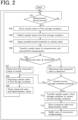
- the measurement controller 38 switches the switching mechanism 24 into a mode where the sample water is introduced into the storage container 22 for a predetermined time so that the sample water is stored in the storage container 22 (step 102).
- the measurement controller 38 makes the syringe pump 2 collect a predetermined amount of sample water out of the whole sample water stored in the storage container 22 (step 103), and performs a control such that the collected sample water is transferred to the reactor 8, and the reactor 8 performs oxidation treatment or the like of the sample water (step 104).
- the measurement controller 38 transfers the sample water to the measurement cell 12 and measures absorbance of the sample water (step 105).
- the determination part 40 compares a measured value obtained in the measurement with a threshold, and determines whether the measured value is normal or abnormal (Steps 106, 107, and 110).
- the first storage controller 42 opens the electromagnetic valve 26 so as to discharge the sample water remaining in the storage container 22 (first storage container) to the drain (step 108).
- the measured value obtained by the measurement is stored in the measured value storing part 48 in association with the determination result by the determination part 40 (step 109) .
- the second storage controller 44 checks the availability of the storage container 32 based on the history and the like of the transfer operation from the first storage container 22 to the storage container 32 (second storage container) (step 111), and when there is an empty storage container 32, the second storage controller 44 performs a control such that the sample water in the storage container 22 is transferred to the storage container 32 (step 112) . Also in this case, the measured value obtained by the measurement is stored in the measured value storing part 48 in association with the determination result by the determination part 40 (step 113), and the notification of the determination result to a user is performed (step 114) .
- the second storage controller 44 does not perform the operation of transferring the sample water from the storage container 22 to the storage container 32, and the first storage controller 42 discharges the sample water remaining in the storage container 22 to the drain (step 108).
Landscapes
- Life Sciences & Earth Sciences (AREA)
- Chemical & Material Sciences (AREA)
- Physics & Mathematics (AREA)
- Health & Medical Sciences (AREA)
- General Physics & Mathematics (AREA)
- Analytical Chemistry (AREA)
- Biochemistry (AREA)
- General Health & Medical Sciences (AREA)
- Immunology (AREA)
- Pathology (AREA)
- Spectroscopy & Molecular Physics (AREA)
- Engineering & Computer Science (AREA)
- Food Science & Technology (AREA)
- Medicinal Chemistry (AREA)
- Hydrology & Water Resources (AREA)
- Dispersion Chemistry (AREA)
- Automatic Analysis And Handling Materials Therefor (AREA)
Claims (6)
- Wasserqualitätsanalysegerät, umfassend:ein Probenreservoir (20), das einen ersten Lagerbehälter (22) beinhaltet, der so konfiguriert ist, dass er Probenwasser vorübergehend lagert, das von einer Probenwasserquelle zugeführt wird, und einen Abgabemechanismus (24), der so konfiguriert ist, dass er das Probenwasser an eine Außenseite des ersten Lagerbehälters (22) abgibt;mindestens einen zweiten Lagerbehälter (32), der als ein Behälter bereitgestellt ist, der sich von dem ersten Lagerbehälter (22) zum Speichern des Probenwassers unterscheidet;eine Messvorrichtung (10), die eine Messzelle (12) zum Aufnehmen von Probenwasser beinhaltet, wobei die Messvorrichtung (10) so konfiguriert ist, dass sie einen Messwert einer physikalischen Größe erhält, die dem Probenwasser zugehörig ist, das in der Messzelle (12) aufgenommen wird;eine Pumpe (2), die so konfiguriert ist, dass sie ein Fluid ansaugt und abgibt, wobei die Pumpe (2) mit einem beliebigen des ersten Lagerbehälters (22), des zweiten Lagerbehälters (32) oder der Messzelle (12) selektiv fluidverbunden ist;eine Schaltvorrichtung (4; 6), die so konfiguriert ist, dass sie die Fluidverbindung der Pumpe (2) mit dem ersten Lagerbehälter (22), dem zweiten Lagerbehälter (32) und der Messzelle (12) schaltet;ein Bestimmungsteil (40), das so konfiguriert ist, dass es bestimmt, ob der gemessene Wert normal oder anormal ist, indem es den gemessenen Wert mit einem voreingestellten Schwellenwert vergleicht;eine Messsteuerung (38), die so konfiguriert ist, dass sie das Probenwasser, das in dem ersten Lagerbehälter (22) gespeichert ist, unter Verwendung der Pumpe (2) zu der Messzelle (12) überführt und eine Messung des Probenwassers durch Steuern eines Betriebs der Pumpe (2) und eines Betriebs der Schaltvorrichtung (4; 6) durchführt;eine erste Lagersteuerung (42), die so konfiguriert ist, dass sie einen Betrieb des Probenreservoirs (20) steuert,wobei die erste Lagersteuerung (42) so konfiguriert ist, dass sie, nachdem ein Abschnitt des Probenwassers, das in dem ersten Lagerbehälter (22) gespeichert ist, durch die Pumpe (2) der Messzelle (12) zugeführt wurde, dafür sorgt, dass das Probenwasser, das in dem ersten Lagerbehälter (22) gespeichert ist, in dem ersten Lagerbehälter (22) verbleibt, bis das Bestimmungsteil (40) den Messwert des Probenwassers bestimmt, das der Messzelle (12) zugeführt wird,wobei die erste Lagersteuerung (42) so konfiguriert ist, dass sie das Probenwasser, das in dem ersten Lagerbehälter (22) verbleibt, an die Außenseite des ersten Lagerbehälters (22) abgibt, in einem Fall, in dem das Bestimmungsteil (40) bestimmt, dass der Messwert, der von der Messvorrichtung (10) erhalten wird, normal ist; undeine zweite Lagersteuerung (44), die so konfiguriert ist, dass sie, in einem Fall, in dem das Bestimmungsteil (40) bestimmt, dass der Messwert, der von der Messvorrichtung (10) erhalten wird, anormal ist, die Pumpe (2) mit dem ersten Lagerbehälter fluidverbindet, um das Probenwasser, das in dem ersten Lagerbehälter (22) verbleibt, durch die Pumpe (2) anzusaugen, und dann die Pumpe (2) mit dem zweiten Lagerbehälter (32) fluidverbindet, um das angesaugte Probenwasser durch die Pumpe (2) in den zweiten Lagerbehälter (32) zu überführen, und wobeidie Messsteuerung (38) so konfiguriert ist, dass sie, wenn eine Anweisung zum Durchführen einer Messung von Probenwasser, das in dem zweiten Lagerbehälter (32) gespeichert ist, in die Messsteuerung (38) eingegeben wird, einen Betrieb der Pumpe (2) und einen Betrieb der Schaltvorrichtung (4; 6) steuert, um die Pumpe (2) mit dem zweiten Lagerbehälter (32) fluidzuverbinden, um das Probenwasser, das in dem zweiten Lagerbehälter (32) gespeichert ist, durch die Pumpe (2) anzusaugen, dann die Pumpe (2) mit der Messzelle (12) fluidzuverbinden, um das angesaugte Probenwasser durch die Pumpe (2) zu der Messzelle (12) zu überführen und dann eine Messung des Probenwassers durchzuführen.
- Wasserqualitätsanalysegerät nach Anspruch 1, ferner umfassend ein Messwertspeicherteil (48), das einen Messwert, der von der Messvorrichtung (10) erhalten wird, in Verbindung mit einem Bestimmungsergebnis bezüglich des Messwerts durch das Bestimmungsteil (40) mindestens in einem Fall speichert, in dem das Bestimmungsteil (40) bestimmt, dass der Messwert, der von der Messvorrichtung (10) erhalten wird, anormal ist.
- Wasserqualitätsanalysegerät nach Anspruch 2, wobeidas Wasserqualitätsanalysegerät eine Vielzahl von zweiten Lagerbehältern (32) beinhaltet, unddas Messwertspeicherteil (48) den Messwert, der von dem Bestimmungsteil (40) als anormal bestimmt wurde, speichert und der zweite Lagerbehälter (32), in dem das Probenwasser, das dem Messwert entspricht, miteinander in Verbindung gespeichert ist.
- Wasserqualitätsanalysegerät nach Anspruch 1, wobei,
in einem Fall, in dem zu dem Zeitpunkt, zu dem das Bestimmungsteil (40) bestimmt, dass der gemessene Wert anormal ist, kein leerer zweiter Lagerbehälter (32) vorhanden ist, die zweite Lagersteuerung (44) so konfiguriert ist, dass sie einen Betrieb zum Überführen des Probenwassers, das in dem ersten Lagerbehälter (22) verbleibt, in einen leeren zweiten Lagerbehälter (32) nicht durchführt, und die erste Lagersteuerung (22) so konfiguriert ist, dass sie das Probenwasser, das in dem ersten Lagerbehälter (22) verbleibt, an die Außenseite des ersten Lagerbehälters (22) abgibt. - Wasserqualitätsanalysegerät nach Anspruch 1, wobeidas Probenreservoir (20) einen Rührmechanismus (28) zum Rühren einer Innenseite des ersten Lagerbehälters (22) beinhaltet, unddie zweite Lagersteuerung (44) so konfiguriert ist, dass sie das Probenreservoir (20) so steuert, dass der Rührmechanismus (28) die Innenseite des ersten Lagerbehälters (22) rührt, bevor das Probenwasser in dem ersten Lagerbehälter (22) in den zweiten Lagerbehälter (32) überführt wird.
- Wasserqualitätsanalysegerät nach Anspruch 1, ferner umfassend ein Benachrichtigungsteil (46), das so konfiguriert ist, dass es einen Benutzer benachrichtigt, dass das Probenwasser in dem ersten Lagerbehälter (22) in den zweiten Lagerbehälter (32) überführt wurde, wenn das Probenwasser in dem ersten Lagerbehälter (22) in den zweiten Lagerbehälter (32) überführt wurde.
Applications Claiming Priority (2)
| Application Number | Priority Date | Filing Date | Title |
|---|---|---|---|
| JP2019003149 | 2019-01-11 | ||
| PCT/JP2019/039119 WO2020144902A1 (ja) | 2019-01-11 | 2019-10-03 | 水質分析計 |
Publications (3)
| Publication Number | Publication Date |
|---|---|
| EP3910330A1 EP3910330A1 (de) | 2021-11-17 |
| EP3910330A4 EP3910330A4 (de) | 2022-08-31 |
| EP3910330B1 true EP3910330B1 (de) | 2024-12-04 |
Family
ID=71521221
Family Applications (1)
| Application Number | Title | Priority Date | Filing Date |
|---|---|---|---|
| EP19909611.6A Active EP3910330B1 (de) | 2019-01-11 | 2019-10-03 | Analysator für wasserqualität |
Country Status (5)
| Country | Link |
|---|---|
| US (1) | US12085551B2 (de) |
| EP (1) | EP3910330B1 (de) |
| JP (1) | JP7215497B2 (de) |
| CN (1) | CN113302490B (de) |
| WO (1) | WO2020144902A1 (de) |
Families Citing this family (1)
| Publication number | Priority date | Publication date | Assignee | Title |
|---|---|---|---|---|
| TWI895179B (zh) * | 2024-11-20 | 2025-08-21 | 財團法人工業技術研究院 | 水質檢測設備及應用其之水質檢測方法 |
Family Cites Families (21)
| Publication number | Priority date | Publication date | Assignee | Title |
|---|---|---|---|---|
| JPS5114399B1 (de) * | 1970-12-18 | 1976-05-08 | ||
| JPS5114399A (en) * | 1974-07-26 | 1976-02-04 | Glory Kogyo Kk | Jidohanbaikino hanbaikairo |
| JPS5125192A (ja) * | 1974-08-26 | 1976-03-01 | Mitsubishi Heavy Ind Ltd | Suishitsubunsekikeino jidoijokanshihoho |
| JPS57186168A (en) * | 1981-05-12 | 1982-11-16 | Toshiba Corp | Method and apparatus for monitoring and measuring water pollution |
| US4517302A (en) * | 1982-11-15 | 1985-05-14 | Technicon Instruments Corporation | Continuous flow metering apparatus |
| US5013488A (en) * | 1990-03-19 | 1991-05-07 | Khodabandeh Abadi | Apparatus for control of hard water scale in evaporative coolers |
| JP2001153763A (ja) * | 1999-11-30 | 2001-06-08 | Kawasaki Steel Corp | 液体の連続サンプリング装置および方法 |
| JP2004069448A (ja) * | 2002-08-06 | 2004-03-04 | Shimadzu Corp | 試料前処理器 |
| JP2007093209A (ja) * | 2005-09-26 | 2007-04-12 | Shimadzu Corp | 水質分析計 |
| US7311818B1 (en) * | 2006-09-28 | 2007-12-25 | Benjamin Gurfinkel | Water separation unit |
| JP5272429B2 (ja) * | 2008-02-14 | 2013-08-28 | 東亜ディーケーケー株式会社 | 水質測定装置 |
| US7504028B1 (en) * | 2008-02-22 | 2009-03-17 | Benjamin Gurfinkel | Water-contaminant separation system |
| JP5728196B2 (ja) * | 2010-01-21 | 2015-06-03 | シスメックス株式会社 | 試料調製装置および試料調製方法 |
| JP6386334B2 (ja) * | 2014-10-10 | 2018-09-05 | 株式会社トプコン | 干渉計装置 |
| JP6394263B2 (ja) * | 2014-10-14 | 2018-09-26 | 株式会社島津製作所 | 水質分析計 |
| CN106957080B (zh) * | 2016-01-08 | 2022-03-22 | 松下知识产权经营株式会社 | 水处理方法和水处理装置 |
| JP2017223583A (ja) * | 2016-06-16 | 2017-12-21 | 株式会社島津製作所 | 水質分析計 |
| JP6665751B2 (ja) | 2016-10-05 | 2020-03-13 | 株式会社島津製作所 | 水質分析計 |
| US10591408B2 (en) * | 2017-06-20 | 2020-03-17 | Ci Systems (Israel) Ltd. | Flow cell and optical system for analyzing fluid |
| JP7180242B2 (ja) * | 2018-09-26 | 2022-11-30 | 株式会社島津製作所 | 試料搬送装置 |
| US10627384B1 (en) * | 2019-03-07 | 2020-04-21 | Shimadzu Corporation | Water quality analyzer |
-
2019
- 2019-10-03 EP EP19909611.6A patent/EP3910330B1/de active Active
- 2019-10-03 US US17/420,239 patent/US12085551B2/en active Active
- 2019-10-03 CN CN201980088579.2A patent/CN113302490B/zh active Active
- 2019-10-03 WO PCT/JP2019/039119 patent/WO2020144902A1/ja not_active Ceased
- 2019-10-03 JP JP2020565579A patent/JP7215497B2/ja active Active
Also Published As
| Publication number | Publication date |
|---|---|
| CN113302490B (zh) | 2024-08-30 |
| EP3910330A1 (de) | 2021-11-17 |
| US20220065839A1 (en) | 2022-03-03 |
| CN113302490A (zh) | 2021-08-24 |
| US12085551B2 (en) | 2024-09-10 |
| JP7215497B2 (ja) | 2023-01-31 |
| EP3910330A4 (de) | 2022-08-31 |
| WO2020144902A1 (ja) | 2020-07-16 |
| JPWO2020144902A1 (ja) | 2021-10-21 |
Similar Documents
| Publication | Publication Date | Title |
|---|---|---|
| US11054433B2 (en) | Automated analyzer and control method for same | |
| US20130260414A1 (en) | Sample analyzing system, sample analyzer, and management method of sample analyzing system | |
| JP6394263B2 (ja) | 水質分析計 | |
| EP4036573A1 (de) | Verfahren zum nachweis der anwesenheit oder abwesenheit eines gerinnsels in einem flüssigprobenanalysator | |
| CN111766208B (zh) | 一种智能化多参数水质分析仪及分析方法 | |
| US12085551B2 (en) | Water quality analyzer | |
| JP3933499B2 (ja) | 試料分析装置および試料分析システムおよびそれらに使用される容器およびラック。 | |
| EP4024050B1 (de) | Automatisierter analysator | |
| JP7542598B2 (ja) | 電解質分析装置 | |
| US11293874B2 (en) | Analysis device for determining a measurand representing a silicate concentration in a sample liquid | |
| EP2784514A1 (de) | Reagenzbereitstellungsvorrichtung, Probenanalysegerät, Verfahren zur Reagenzbereitstellung und Lagerungsmedium | |
| JP7195452B2 (ja) | 自動分析装置 | |
| US10345321B2 (en) | Automatic analyzer and method | |
| JP3238318U (ja) | 水質分析計 | |
| US12618814B2 (en) | Monitoring system and monitoring method | |
| US20250035478A1 (en) | Automatic analyzer | |
| US10627384B1 (en) | Water quality analyzer | |
| JP6958636B2 (ja) | 水質分析計 | |
| KR102722361B1 (ko) | 산 분석이 가능한 xrf 분석장치 | |
| JP7229060B2 (ja) | 自動分析装置 | |
| WO2025013646A1 (ja) | 自動分析装置 | |
| WO2025158807A1 (ja) | 自動分析装置、および自動分析装置における異常の有無を判定する方法 | |
| JPH04320960A (ja) | 自動液管理装置 | |
| JP2020063998A (ja) | 水質分析計及び紫外線ランプの劣化判定方法 | |
| JPH03214617A (ja) | 自動液管理装置 |
Legal Events
| Date | Code | Title | Description |
|---|---|---|---|
| STAA | Information on the status of an ep patent application or granted ep patent |
Free format text: STATUS: THE INTERNATIONAL PUBLICATION HAS BEEN MADE |
|
| PUAI | Public reference made under article 153(3) epc to a published international application that has entered the european phase |
Free format text: ORIGINAL CODE: 0009012 |
|
| STAA | Information on the status of an ep patent application or granted ep patent |
Free format text: STATUS: REQUEST FOR EXAMINATION WAS MADE |
|
| 17P | Request for examination filed |
Effective date: 20210805 |
|
| AK | Designated contracting states |
Kind code of ref document: A1 Designated state(s): AL AT BE BG CH CY CZ DE DK EE ES FI FR GB GR HR HU IE IS IT LI LT LU LV MC MK MT NL NO PL PT RO RS SE SI SK SM TR |
|
| DAV | Request for validation of the european patent (deleted) | ||
| DAX | Request for extension of the european patent (deleted) | ||
| A4 | Supplementary search report drawn up and despatched |
Effective date: 20220802 |
|
| RIC1 | Information provided on ipc code assigned before grant |
Ipc: G01N 35/10 20060101ALI20220727BHEP Ipc: G01N 33/18 20060101AFI20220727BHEP |
|
| STAA | Information on the status of an ep patent application or granted ep patent |
Free format text: STATUS: EXAMINATION IS IN PROGRESS |
|
| 17Q | First examination report despatched |
Effective date: 20230329 |
|
| GRAP | Despatch of communication of intention to grant a patent |
Free format text: ORIGINAL CODE: EPIDOSNIGR1 |
|
| STAA | Information on the status of an ep patent application or granted ep patent |
Free format text: STATUS: GRANT OF PATENT IS INTENDED |
|
| INTG | Intention to grant announced |
Effective date: 20240627 |
|
| GRAS | Grant fee paid |
Free format text: ORIGINAL CODE: EPIDOSNIGR3 |
|
| GRAA | (expected) grant |
Free format text: ORIGINAL CODE: 0009210 |
|
| STAA | Information on the status of an ep patent application or granted ep patent |
Free format text: STATUS: THE PATENT HAS BEEN GRANTED |
|
| AK | Designated contracting states |
Kind code of ref document: B1 Designated state(s): AL AT BE BG CH CY CZ DE DK EE ES FI FR GB GR HR HU IE IS IT LI LT LU LV MC MK MT NL NO PL PT RO RS SE SI SK SM TR |
|
| REG | Reference to a national code |
Ref country code: CH Ref legal event code: EP |
|
| REG | Reference to a national code |
Ref country code: DE Ref legal event code: R096 Ref document number: 602019063208 Country of ref document: DE |
|
| REG | Reference to a national code |
Ref country code: IE Ref legal event code: FG4D |
|
| REG | Reference to a national code |
Ref country code: LT Ref legal event code: MG9D |
|
| REG | Reference to a national code |
Ref country code: NL Ref legal event code: MP Effective date: 20241204 |
|
| PG25 | Lapsed in a contracting state [announced via postgrant information from national office to epo] |
Ref country code: HR Free format text: LAPSE BECAUSE OF FAILURE TO SUBMIT A TRANSLATION OF THE DESCRIPTION OR TO PAY THE FEE WITHIN THE PRESCRIBED TIME-LIMIT Effective date: 20241204 |
|
| PG25 | Lapsed in a contracting state [announced via postgrant information from national office to epo] |
Ref country code: FI Free format text: LAPSE BECAUSE OF FAILURE TO SUBMIT A TRANSLATION OF THE DESCRIPTION OR TO PAY THE FEE WITHIN THE PRESCRIBED TIME-LIMIT Effective date: 20241204 |
|
| PG25 | Lapsed in a contracting state [announced via postgrant information from national office to epo] |
Ref country code: BG Free format text: LAPSE BECAUSE OF FAILURE TO SUBMIT A TRANSLATION OF THE DESCRIPTION OR TO PAY THE FEE WITHIN THE PRESCRIBED TIME-LIMIT Effective date: 20241204 |
|
| PG25 | Lapsed in a contracting state [announced via postgrant information from national office to epo] |
Ref country code: ES Free format text: LAPSE BECAUSE OF FAILURE TO SUBMIT A TRANSLATION OF THE DESCRIPTION OR TO PAY THE FEE WITHIN THE PRESCRIBED TIME-LIMIT Effective date: 20241204 |
|
| PG25 | Lapsed in a contracting state [announced via postgrant information from national office to epo] |
Ref country code: NO Free format text: LAPSE BECAUSE OF FAILURE TO SUBMIT A TRANSLATION OF THE DESCRIPTION OR TO PAY THE FEE WITHIN THE PRESCRIBED TIME-LIMIT Effective date: 20250304 |
|
| PG25 | Lapsed in a contracting state [announced via postgrant information from national office to epo] |
Ref country code: GR Free format text: LAPSE BECAUSE OF FAILURE TO SUBMIT A TRANSLATION OF THE DESCRIPTION OR TO PAY THE FEE WITHIN THE PRESCRIBED TIME-LIMIT Effective date: 20250305 Ref country code: LV Free format text: LAPSE BECAUSE OF FAILURE TO SUBMIT A TRANSLATION OF THE DESCRIPTION OR TO PAY THE FEE WITHIN THE PRESCRIBED TIME-LIMIT Effective date: 20241204 |
|
| PG25 | Lapsed in a contracting state [announced via postgrant information from national office to epo] |
Ref country code: RS Free format text: LAPSE BECAUSE OF FAILURE TO SUBMIT A TRANSLATION OF THE DESCRIPTION OR TO PAY THE FEE WITHIN THE PRESCRIBED TIME-LIMIT Effective date: 20250304 |
|
| PG25 | Lapsed in a contracting state [announced via postgrant information from national office to epo] |
Ref country code: NL Free format text: LAPSE BECAUSE OF FAILURE TO SUBMIT A TRANSLATION OF THE DESCRIPTION OR TO PAY THE FEE WITHIN THE PRESCRIBED TIME-LIMIT Effective date: 20241204 |
|
| REG | Reference to a national code |
Ref country code: AT Ref legal event code: MK05 Ref document number: 1748675 Country of ref document: AT Kind code of ref document: T Effective date: 20241204 |
|
| PG25 | Lapsed in a contracting state [announced via postgrant information from national office to epo] |
Ref country code: SM Free format text: LAPSE BECAUSE OF FAILURE TO SUBMIT A TRANSLATION OF THE DESCRIPTION OR TO PAY THE FEE WITHIN THE PRESCRIBED TIME-LIMIT Effective date: 20241204 |
|
| PG25 | Lapsed in a contracting state [announced via postgrant information from national office to epo] |
Ref country code: PL Free format text: LAPSE BECAUSE OF FAILURE TO SUBMIT A TRANSLATION OF THE DESCRIPTION OR TO PAY THE FEE WITHIN THE PRESCRIBED TIME-LIMIT Effective date: 20241204 |
|
| PG25 | Lapsed in a contracting state [announced via postgrant information from national office to epo] |
Ref country code: IS Free format text: LAPSE BECAUSE OF FAILURE TO SUBMIT A TRANSLATION OF THE DESCRIPTION OR TO PAY THE FEE WITHIN THE PRESCRIBED TIME-LIMIT Effective date: 20250404 |
|
| PG25 | Lapsed in a contracting state [announced via postgrant information from national office to epo] |
Ref country code: PT Free format text: LAPSE BECAUSE OF FAILURE TO SUBMIT A TRANSLATION OF THE DESCRIPTION OR TO PAY THE FEE WITHIN THE PRESCRIBED TIME-LIMIT Effective date: 20250404 |
|
| PG25 | Lapsed in a contracting state [announced via postgrant information from national office to epo] |
Ref country code: EE Free format text: LAPSE BECAUSE OF FAILURE TO SUBMIT A TRANSLATION OF THE DESCRIPTION OR TO PAY THE FEE WITHIN THE PRESCRIBED TIME-LIMIT Effective date: 20241204 |
|
| PG25 | Lapsed in a contracting state [announced via postgrant information from national office to epo] |
Ref country code: AT Free format text: LAPSE BECAUSE OF FAILURE TO SUBMIT A TRANSLATION OF THE DESCRIPTION OR TO PAY THE FEE WITHIN THE PRESCRIBED TIME-LIMIT Effective date: 20241204 Ref country code: RO Free format text: LAPSE BECAUSE OF FAILURE TO SUBMIT A TRANSLATION OF THE DESCRIPTION OR TO PAY THE FEE WITHIN THE PRESCRIBED TIME-LIMIT Effective date: 20241204 |
|
| PG25 | Lapsed in a contracting state [announced via postgrant information from national office to epo] |
Ref country code: SK Free format text: LAPSE BECAUSE OF FAILURE TO SUBMIT A TRANSLATION OF THE DESCRIPTION OR TO PAY THE FEE WITHIN THE PRESCRIBED TIME-LIMIT Effective date: 20241204 |
|
| PG25 | Lapsed in a contracting state [announced via postgrant information from national office to epo] |
Ref country code: CZ Free format text: LAPSE BECAUSE OF FAILURE TO SUBMIT A TRANSLATION OF THE DESCRIPTION OR TO PAY THE FEE WITHIN THE PRESCRIBED TIME-LIMIT Effective date: 20241204 |
|
| REG | Reference to a national code |
Ref country code: DE Ref legal event code: R097 Ref document number: 602019063208 Country of ref document: DE |
|
| PG25 | Lapsed in a contracting state [announced via postgrant information from national office to epo] |
Ref country code: SE Free format text: LAPSE BECAUSE OF FAILURE TO SUBMIT A TRANSLATION OF THE DESCRIPTION OR TO PAY THE FEE WITHIN THE PRESCRIBED TIME-LIMIT Effective date: 20241204 |
|
| PG25 | Lapsed in a contracting state [announced via postgrant information from national office to epo] |
Ref country code: DK Free format text: LAPSE BECAUSE OF FAILURE TO SUBMIT A TRANSLATION OF THE DESCRIPTION OR TO PAY THE FEE WITHIN THE PRESCRIBED TIME-LIMIT Effective date: 20241204 |
|
| PLBE | No opposition filed within time limit |
Free format text: ORIGINAL CODE: 0009261 |
|
| STAA | Information on the status of an ep patent application or granted ep patent |
Free format text: STATUS: NO OPPOSITION FILED WITHIN TIME LIMIT |
|
| PGFP | Annual fee paid to national office [announced via postgrant information from national office to epo] |
Ref country code: IT Payment date: 20250922 Year of fee payment: 7 |
|
| REG | Reference to a national code |
Ref country code: CH Ref legal event code: L10 Free format text: ST27 STATUS EVENT CODE: U-0-0-L10-L00 (AS PROVIDED BY THE NATIONAL OFFICE) Effective date: 20251015 |
|
| PGFP | Annual fee paid to national office [announced via postgrant information from national office to epo] |
Ref country code: GB Payment date: 20250828 Year of fee payment: 7 |
|
| REG | Reference to a national code |
Ref country code: CH Ref legal event code: U11 Free format text: ST27 STATUS EVENT CODE: U-0-0-U10-U11 (AS PROVIDED BY THE NATIONAL OFFICE) Effective date: 20251101 |
|
| 26N | No opposition filed |
Effective date: 20250905 |
|
| PGFP | Annual fee paid to national office [announced via postgrant information from national office to epo] |
Ref country code: DE Payment date: 20250902 Year of fee payment: 7 |
|
| PGFP | Annual fee paid to national office [announced via postgrant information from national office to epo] |
Ref country code: CH Payment date: 20251101 Year of fee payment: 7 |