EP3911459B1 - Elektromagnetische vorrichtung zur seitlichen aufnahme von flüssigem metall beim giessen von metallprodukten - Google Patents
Elektromagnetische vorrichtung zur seitlichen aufnahme von flüssigem metall beim giessen von metallprodukten Download PDFInfo
- Publication number
- EP3911459B1 EP3911459B1 EP20705106.1A EP20705106A EP3911459B1 EP 3911459 B1 EP3911459 B1 EP 3911459B1 EP 20705106 A EP20705106 A EP 20705106A EP 3911459 B1 EP3911459 B1 EP 3911459B1
- Authority
- EP
- European Patent Office
- Prior art keywords
- casting
- wedge
- plate
- casting rolls
- aluminum
- Prior art date
- Legal status (The legal status is an assumption and is not a legal conclusion. Google has not performed a legal analysis and makes no representation as to the accuracy of the status listed.)
- Active
Links
Images


Classifications
-
- B—PERFORMING OPERATIONS; TRANSPORTING
- B22—CASTING; POWDER METALLURGY
- B22D—CASTING OF METALS; CASTING OF OTHER SUBSTANCES BY THE SAME PROCESSES OR DEVICES
- B22D11/00—Continuous casting of metals, i.e. casting in indefinite lengths
- B22D11/06—Continuous casting of metals, i.e. casting in indefinite lengths into moulds with travelling walls, e.g. with rolls, plates, belts, caterpillars
- B22D11/0622—Continuous casting of metals, i.e. casting in indefinite lengths into moulds with travelling walls, e.g. with rolls, plates, belts, caterpillars formed by two casting wheels
-
- B—PERFORMING OPERATIONS; TRANSPORTING
- B22—CASTING; POWDER METALLURGY
- B22D—CASTING OF METALS; CASTING OF OTHER SUBSTANCES BY THE SAME PROCESSES OR DEVICES
- B22D11/00—Continuous casting of metals, i.e. casting in indefinite lengths
- B22D11/06—Continuous casting of metals, i.e. casting in indefinite lengths into moulds with travelling walls, e.g. with rolls, plates, belts, caterpillars
- B22D11/0637—Accessories therefor
- B22D11/0648—Casting surfaces
- B22D11/066—Side dams
- B22D11/0662—Side dams having electromagnetic confining means
-
- B—PERFORMING OPERATIONS; TRANSPORTING
- B22—CASTING; POWDER METALLURGY
- B22D—CASTING OF METALS; CASTING OF OTHER SUBSTANCES BY THE SAME PROCESSES OR DEVICES
- B22D11/00—Continuous casting of metals, i.e. casting in indefinite lengths
- B22D11/06—Continuous casting of metals, i.e. casting in indefinite lengths into moulds with travelling walls, e.g. with rolls, plates, belts, caterpillars
- B22D11/0637—Accessories therefor
- B22D11/068—Accessories therefor for cooling the cast product during its passage through the mould surfaces
-
- B—PERFORMING OPERATIONS; TRANSPORTING
- B22—CASTING; POWDER METALLURGY
- B22D—CASTING OF METALS; CASTING OF OTHER SUBSTANCES BY THE SAME PROCESSES OR DEVICES
- B22D11/00—Continuous casting of metals, i.e. casting in indefinite lengths
- B22D11/08—Accessories for starting the casting procedure
-
- B—PERFORMING OPERATIONS; TRANSPORTING
- B22—CASTING; POWDER METALLURGY
- B22D—CASTING OF METALS; CASTING OF OTHER SUBSTANCES BY THE SAME PROCESSES OR DEVICES
- B22D11/00—Continuous casting of metals, i.e. casting in indefinite lengths
- B22D11/10—Supplying or treating molten metal
Definitions
- the present invention relates to an electromagnetic device for laterally containing liquid aluminum, in a casting of flat products, e.g. strips, according to technology commonly known as Twin Roll Casting.
- aluminum means both pure aluminum and any aluminum alloy.
- Twin Roll Casting The technology commonly known as Twin Roll Casting is widely used in the production of aluminum strips and is characterized by the direct feeding of the liquid aluminum between two counter-rotating steel rolls, which are cooled, e.g. by water.
- this process requires a lateral containment of the cast aluminum in order to increase productivity and avoid material accumulation on the edges, with the consequent need to clean the solidified material waste from the edges themselves.
- the present invention achieves at least one of such objects, and other objects which will be apparent in light of the present description, by means of an electromagnetic device for laterally containing liquid aluminum or a liquid alloy thereof, having a first electrical conductivity in a range from about 7 to 15 MS/m at a first temperature in a range from about 510°C to 720°C, at one open side end of a passage defined between two counter-rotating casting rolls, said device comprising
- Another aspect of the invention relates to a casting machine for casting flat products made of aluminum or alloys thereof, comprising
- a further aspect of invention relates to a casting process for casting flat products made of aluminum or alloys thereof, performed by means of the aforesaid casting machine, the process comprising the following steps:
- the solution of the electromagnetic device or edge dam of the invention allows to meet the following requirements:
- the casting machine of the invention further exploits the magnetic properties of the casting rolls, preferably made of steel (at least on the outer part thereof, in contact with the product to be solidified), to convey the magnetic field generated by the at least one coil, first between said coil and a casting roll and then between the casting roll and the aluminum product in the step of casting, thus generating eddy currents by induction, which, by interacting with the magnetic field, produce the Lorentz forces capable of contrasting the liquid aluminum head on the edge of the aluminum product.
- the magnetic properties of the casting rolls preferably made of steel (at least on the outer part thereof, in contact with the product to be solidified)
- the magnetic yoke can be made in a single piece of ferromagnetic material or made of a plurality of ferromagnetic sheets arranged on top of each other, or side by side, and electrically insulated from one another.
- the choice of the magnetic yoke material is important because the magnetic yoke as a whole must have a low electrical conductivity which significantly reduces the generation of eddy currents and therefore the need to cool the yoke intensively.
- a better heat exchange between the metal of the casting product and the casting roll allows higher productivity (e.g. 10m/min for aluminum strip thicknesses of 5 mm) and greater flexibility in production control.
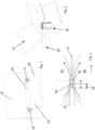
- Figure 1 shows an example of a horizontal casting machine comprising a pair of electromagnetic devices 20, 21, which are the object of the present invention.
- the electromagnetic devices of the present invention can also be used in vertical casting machines.
- the casting machine in the horizontal version of which is illustrated in the Figures, for casting flat products, e.g. strips, made of aluminum or alloys thereof, comprises:
- aluminum means both pure aluminum and any aluminum alloy with at least one metal, e.g. copper, zinc, manganese, silicon, or magnesium.
- the aforesaid casting machine can not be equipped with any mechanical lateral containment device.
- At least the outer surfaces of the casting rolls 22, 22' are made of a ferromagnetic material, e.g. ferromagnetic steel.
- the feeding means comprise:
- Moving means 60 can be provided for moving the first electromagnetic device 20 and/or the second electromagnetic device 21 so as to adjust the distance from one another along a direction Z ( Figure 4 ) parallel to a plane containing the rotation axes of the two casting rolls 22, 22'.
- Such moving means 60 can be, for example, linear, hydraulic, pneumatic, mechanical, pneumatic actuators, combinations thereof or the like.
- the width of the casting rolls being the same, said width being fixed, the electromagnetic lateral containment device can be moved so as to define different widths of the strip to be cast, and therefore it is not necessary to have dedicated sets of rolls as in the prior art, in which the electromagnetic device cannot be displaced laterally and, therefore, the casting rolls must be changed whenever it is necessary to cast strips of different widths.
- Each electromagnetic device 20, 21, suited for the lateral containment of the liquid aluminum during casting, at the respective open side end of the passage defined between the two casting rolls 22, 22', comprises:
- the outer surfaces 7, 7' of the two wedge-shaped ends 4, 4' are shaped so that both said wedge-shaped ends 4, 4' can be inserted at least partially between the two casting rolls 22, 22'.
- the temperature of aluminum and alloys thereof is comprised in the range from about 510°C to 720°C. At this temperature the electrical conductivity of aluminum and alloys thereof is in the range from about 7 to 15 MS/m.
- the temperature of the aluminum in the step of casting is in the range from about 660°C to 700°C.
- the electrical conductivity of aluminum is comprised in the range from 9 to 11 MS/m.
- the plate 9 is made of a material chosen from the following: copper, silver or other suitable metal.
- the electrical conductivity of the material of the plate 9 during said step of casting is at least 20 MS/m, e.g. about 40 MS/m.
- the temperature of the plate 9 is kept in the range from about 170°C to 200°C, during the casting of the aluminum or an alloy thereof.
- the magnetic yoke 1 is made of a ferromagnetic material, e.g. chosen from the following: silicon steel, "Fluxtrol” materials, e.g. Fluxtrol 100, or “Grey T Type” made by MagShape, or anyway materials having magneto-dielectric properties, due to the doping between iron elements and plastic elements constituting the magnetic yoke 1, which imply the reduction of the internal heating phenomenon due to the formation of eddy currents.
- a ferromagnetic material e.g. chosen from the following: silicon steel, "Fluxtrol” materials, e.g. Fluxtrol 100, or “Grey T Type” made by MagShape, or anyway materials having magneto-dielectric properties, due to the doping between iron elements and plastic elements constituting the magnetic yoke 1, which imply the reduction of the internal heating phenomenon due to the formation of eddy currents.
- the electrical conductivity of the ferromagnetic material of the magnetic yoke 1 during the aforesaid step of casting is less than or equal to 500 S/m, preferably less than or equal to 100 S/m.
- the temperature of the magnetic yoke 1 is kept in the range from about 170°C to 200°C, during the casting of aluminum or an alloy thereof.
- each electromagnetic device 20, 21, and thus the respective magnetic yoke 1 is positioned laterally and in an outer position, e.g. completely outside, with respect to the zone occupied by the unloader or the feed tip 35.
- the magnetic yoke 1 is not profiled to adapt to the unloader 35.
- the magnetic yoke 1 is instead profiled to define the aforesaid gap 6 in which the plate 9 is inserted, said plate being made of a conductive and magnetic material such as to electromagnetically shield the inner surfaces 5, 5', which are preferably flat and substantially parallel to each other. Therefore, the plate 9 is not transparent to the magnetic fields generated by the electromagnetic device.
- the gap or distance 6 between the inner surfaces 5, 5', facing each other, of the two wedge-shaped ends 4, 4' is in a range from 2 to 25 mm, preferably 4 to 8 mm.
- the plate 9, or at least the part of plate 9 arranged between the two inner surfaces 5, 5' has a thickness in the range from 1.5 to 24.5 mm, preferably from 3.5 to 7.5 mm. Therefore, due to the shape of the outer surfaces 7, 7' of the wedge-shaped ends 4, 4', and due to the fact that the gap 6 and, therefore, the plate 9 are very thin, the magnetic field flux, appropriately diverted by the plate 9, enters into a casting roll and crosses the space between the casting rolls, crossing the aluminum to be cast, in a point in which this space is very narrow.
- the magnetic field flux between the casting rolls makes a path of about 5-6 cm when it exits the wedge-shaped end 4 and then closes in the other wedge-shaped end 4'.
- the two wedge-shaped ends 4, 4' are arranged symmetrically with respect to a symmetry plane lying in the gap 6, with the respective inner surfaces 5, 5' substantially parallel and proximal to said symmetry plane, and the respective outer surfaces 7, 7', flat or curved, distal from the symmetry plane but substantially converging towards said symmetry plane so as to define the wedge shape.
- the outer surfaces 7, 7' of the wedge-shaped ends 4, 4' are curvilinear with a radius of curvature substantially equal to the outer radius of the corresponding casting roll.
- Each wedge-shaped end 4, 4' is also provided with two further lateral surfaces 26 that are transverse, preferably perpendicular, to the inner surface 5, 5', and joining the inner surface 5, 5' to the respective outer surface 7, 7'.
- the lateral containment of the liquid aluminum is achieved by supplying electrical current to at least one coil 8 so that, by virtue of the magnetic properties of the materials of some components of the casting machine and the relation between the electrical conductivities of the different materials used, the magnetic field flux produced by the coil 8 passes in succession, as shown in Figure 9 :
- the passage of the magnetic field flux from the first roll 22 to the second roll 22' is substantially vertical; while, if the casting process is performed by means of a vertical casting machine, the passage of the magnetic field flux from the first roll 22 to the second roll 22' is substantially horizontal.
- the minimum distance between the electromagnetic device and the casting roll i.e. the minimum distance between the outer surfaces 7, 7' of the wedge-shaped ends 4, 4' and the corresponding casting roll, is about 0.5-2 mm, e.g. about 1 mm.
- the distance between the electromagnetic device and the liquid aluminum is about 8-12 mm, e.g. 10 mm.
- the electrical conductivity of the material of the plate 9 prevents the magnetic field from closing in the yoke itself, thereby conveying the magnetic field flux from the wedge-shaped end 4 towards the surface of the proximal casting roll 22, made of ferromagnetic material, thus promoting the containment force.
- FIGs 1-4 A solidification process of the liquid aluminum through the casting machine is shown in Figures 1-4 .
- the products e.g. strips or sheets
- the unloading device 35 A cross-section of the solidification region is shown in Figure 3 .
- a solid shell starts forming, growing towards outlet passage 38.
- the electromagnetic device or edge dam 20 is used to handle the aluminum by applying pressure along the sump depth 39 ( Figure 3 , corresponding to the actual solidification length) during casting.
- This pressure controls the position of the side edge of the aluminum in the region between the unloader 35 and the outlet passage 38, where a real physical containment is absent.
- Diagrammatically in Figure 4 in which the direction of casting is indicated by reference numeral 44, the region in which the liquid aluminum is physically contained inside the unloader 35 is indicated by reference numeral 40; the solidification region in which the liquid aluminum is not physically contained laterally is indicated by reference numeral 41; the region in which the cast product is completely solid and reduced in thickness is indicated by the reference numeral 42; and the lateral region (circled in Figure 4 ) in which the liquid aluminum is contained by the Lorentz Forces, by means of the electromagnetic device 20, is indicated by the reference numeral 43.
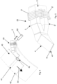
- the magnetic yoke 1 has the body 2 provided with two arms 3, 3', each arm ending with the respective wedge-shaped end 4, 4'.
- the two wedge-shaped ends 4, 4' are arranged one above the other.
- the arms 3, 3' comprise:
- the body 2 is provided with an further stretch 45 connecting the first stretches 11, 11' and arranged in a distal position from the wedge-shaped ends 4, 4'.
- the first stretches 11, 11' and second stretches 12, 12' are arranged along a first plane, and third curved stretches 13, 13' are provided which connect a respective second stretch 12, 12' to the respective wedge-shaped end 4, 4'.
- the two wedge-shaped ends 4, 4' are therefore arranged along a second plane which is inclined with respect to the first plane by an angle greater than 90°, preferably between 120 and 150°.
- the body 2 of magnetic yoke 1 is made of a ferromagnetic material, e.g. silicon steel, and can be formed by a single solid piece of such ferromagnetic material.
- the body 2 of the magnetic yoke 1 can be formed by a series of ferromagnetic sheets which are bent and fixed together, using mechanical means, an adhesive or similar means to provide the desired configuration, said ferromagnetic sheets being insulated from each other by means of insulators, using a technology similar to that used for the composition of the ferromagnetic cores of the transformers.
- the at least one plate 9, preferably a single plate 9, in the variant shown in Figures 8a and 8b comprises a flat part 23 arranged between the inner surfaces 5, 5' of the wedge-shaped ends 4, 4'.
- the thickness of said flat part 23 is preferably in the range from about 1.5 to 24.5 mm, e.g. from 3.5 to 7.5 mm.
- said flat part 23 is provided, at one end thereof, with a bifurcation with diverging stretches 14, 14' substantially parallel to the second stretches 12, 12' of the arms 3, 3' of the magnetic yoke 1.
- the space between the two diverging stretches 14, 14' can be either empty, as shown in the Figures, or full whereby a material block is provided having the aforesaid diverging stretches 14, 14' as two opposite surfaces.
- the flat part 23 has a curved end stretch 24 arranged between the third curved stretches 13, 13' of the magnetic yoke and connected to the diverging stretches 14, 14'.
- the plate 9 is preferably also provided, at a side edge 47 thereof ( Figure 10 ), with a wall 15 ( Figures 8a, 8b ) which is transversal, preferably orthogonal, to the flat part 23 and shaped to cover a side surface 26 of both the wedge-shaped ends 4, 4'.
- the wall 15 is also provided with a respective bifurcation with respective diverging stretches 16, 16' which are transversal, preferably perpendicular, to the diverging stretches 14, 14' of the plate 9 and shaped so as to cover a flank of said second stretches 12, 12' of the body 2 of the magnetic yoke 1.
- a curved stretch 15' connects the main body of the wall 15 to the diverging stretches 16, 16'.
- the plate 9 is fixed to the magnetic yoke 1, e.g. by means of an adhesive binder.
- an adhesive binder Any epoxy adhesive which has the following characteristics can be used:
- the flat part 23, e.g. rectangular, is fixed to the inner surfaces 5, 5' of the wedge-shaped ends 4, 4'; the diverging stretches 14, 14' are fixed to the respective second stretches 12, 12' of the body 2; the curved end stretch 24 is fixed to the third curved stretches 13, 13'; the wall 15 is fixed to the side surfaces 26 of both wedge-shaped ends 4, 4'.
- the curved stretch 15' of the wall 15 is fixed to the inner surfaces of the curved stretches 13, 13' of the body 2, while the diverging stretches 16, 16' of the wall 15 are fixed to a flank of the corresponding second stretch 12, 12' of the body 2.
- the plate 9 can be provided with cooling means.
- These cooling means comprise at least one channel 10 made inside the plate 9, and which can be connected to a supply circuit of cooling liquid, e.g. water.
- a channel 10, inside the plate 9 is made in proximity of two edges of the plate 9, and in particular along the edge 25, corresponding to the tip of the wedge-shaped ends 4, 4', and along the edge 27, i.e. the edge of the plate 9 which in operating position is proximal to the lateral end of the passage of the product to be cast, and therefore distal from wall 15.
- This configuration allows the removal of the heat generated by the Joule effect in the part of the magnetic yoke 1 proximal to the passage of the product to be cast, keeping the yoke temperature below about 180°C.
- the channel 10 has substantially a L-shape in plan, with the short stretch along the edge 25 and the long stretch along the edge 27.
- the cooling liquid supplied by the supply circuit (not shown), enters the channel 10 from an end of the edge 25 and exits the channel 10 from an end of the edge 27.
- the wall 15 is provided with a slot 50 ( Figure 8a ) to let the cooling liquid into the channel 10, at the end of the edge 25.
- the long stretch of the channel 10, along the edge 27, can have a curved end 28 at the curved end stretch 24 of the flat part 23 of the plate.
- the cooling liquid, supplied by the supply circuit enters the channel 10 from an end of the edge 25, proximal to the wall 15, and exits the channel 10 from the curved end thereof, distal from the edge 25.
- suitable cooling systems can be provided to cool the outer walls of the entire wall 15 and of the diverging stretches 14, 14' of the plate 9.
- each coil 8, 8' being wound on a first stretch 11, 11' of a respective arm 3, 3' of the magnetic yoke 1.
- the use of more than two coils is not excluded.
- the coils, e.g. made of copper, are preferably hollow and/or preferably internally watercooled.
- At least one cooling circuit can be provided which runs through at least one first stretch 11, 11' of the arms 3, 3'.
- two cooling circuits are provided, one passing through at least the first stretch 11 of the arm 3 on which the coil 8 is wound, and the other passing through at least the first stretch 11' of the arm 3' on which the coil 8' is wound.
- a respective channel or duct 29, 30, e.g. U-shaped, can be made or inserted inside the arms 3, 3'. Openings 31, 32 for letting the cooling liquid in and out of channel 29 or channels 29, 30, respectively, are provided in the body 2, e.g. in stretch 45.
Landscapes
- Engineering & Computer Science (AREA)
- Mechanical Engineering (AREA)
- Physics & Mathematics (AREA)
- Electromagnetism (AREA)
- Continuous Casting (AREA)
- Casting Support Devices, Ladles, And Melt Control Thereby (AREA)
Claims (17)
- Elektromagnetische Vorrichtung (20) zur seitlichen Aufnahme von flüssigem Aluminium oder einer flüssigen Aluminiumlegierung, das/die eine erste elektrische Leitfähigkeit in einem Bereich von etwa 7 bis 15 MS/m bei einer ersten Temperatur in einem Bereich von etwa 510 °C bis 720 °C aufweist, an einem offenen Seitenende eines Durchgangs, der zwischen zwei gegenläufigen Gusswalzen (22, 22') definiert ist, wobei die Vorrichtung umfasst- ein magnetisches Joch (1) aus einem ersten Material, das eine zweite elektrische Leitfähigkeit von entweder weniger oder gleich 500 S/m bei einer zweiten Temperatur aufweist, die in einem Bereich von etwa 170 °C bis 200 °C liegt, die niedriger als die erste elektrische Leitfähigkeit ist, wobei das erste Material ein ferromagnetisches Material ist und das magnetische Joch mit zwei zueinander proximalen keilförmigen Enden (4, 4') endet, wobei die keilförmigen Enden jeweilige Innenflächen (5, 5'), die einander zugewandt sind und einen Spalt (6) definieren, und jeweilige Außenflächen (7, 7') aufweisen, von denen eine auf einer Seite und die andere auf der anderen Seite in Bezug auf eine in dem Spalt liegende Ebene angeordnet ist;- mindestens eine Spule (8), die um mindestens einen Abschnitt des magnetischen Jochs (1) gewickelt ist und dazu geeignet ist, mit elektrischem Strom versorgt zu werden;- mindestens eine Platte (9), die in den Spalt (6) eingesetzt ist;dadurch gekennzeichnet, dass die mindestens eine Platte (9) aus einem zweiten Material besteht, das bei der zweiten Temperatur eine dritte elektrische Leitfähigkeit von mindestens 20 MS/m aufweist, die größer ist als die erste elektrische Leitfähigkeit bei der ersten Temperatur, wodurch die mindestens eine Platte (9) die Innenflächen (5, 5') in Bezug aufeinander elektromagnetisch abschirmen kann.
- Vorrichtung nach Anspruch 1, wobei die mindestens eine Platte (9) mit Kühlmitteln versehen ist.
- Vorrichtung nach Anspruch 2, wobei die Kühlmittel mindestens einen Kanal (10) umfassen, der im Inneren der mindestens einen Platte (9) gebildet ist und mit einem Kühlflüssigkeitszufuhrkreislauf verbindbar ist.
- Vorrichtung nach einem der vorhergehenden Ansprüche, wobei
die Platte (9) aus einem Material besteht, das aus Kupfer, Silber oder einem anderen geeigneten Metall ausgewählt ist; und wobei das magnetische Joch (1) aus einem ferromagnetischen Material besteht, das aus Siliziumstahl, Fluxtrol-Materialien, "Grey T Type"-Material oder einem anderen geeigneten ferromagnetischen Material ausgewählt ist. - Vorrichtung nach einem der vorhergehende Ansprüche, wobei das magnetische Joch (1) einen Körper (2) aufweist, der mit zwei Armen (3, 3') versehen ist, wobei jeder Arm mit einem jeweiligen keilförmigen Ende (4, 4') endet und vorzugsweise nacheinander jeweilige erste Abschnitte (11, 11'), die voneinander beabstandet und im Wesentlichen parallel sind,
und jeweilige zweite Abschnitte (12, 12') aufweist, die in jeweilige zueinander konvergierende Richtungen geneigt sind, wobei jeder zweite Abschnitt einen jeweiligen ersten Abschnitt (11, 11') mit dem jeweiligen keilförmigen Ende (4, 4') verbindet. - Vorrichtung nach Anspruch 5, wobei die ersten Abschnitte (11, 11') und zweiten Abschnitte (12, 12') entlang einer ersten Ebene angeordnet sind, und dritte gekrümmte Abschnitte (13, 13') vorgesehen sind, die einen jeweiligen zweiten Abschnitt (12, 12') mit dem jeweiligen keilförmigen Ende (4, 4') verbinden; vorzugsweise wobei die keilförmigen Enden (4, 4') entlang einer zweiten Ebene angeordnet sind, die in Bezug auf die erste Ebene um einen Winkel von mehr als 90° geneigt ist.
- Vorrichtung nach Anspruch 1, wobei die mindestens eine Platte (9), vorzugsweise nur eine Platte (9), einen flachen Teil (23) umfasst, der zwischen den Innenflächen (5, 5') der keilförmigen Enden (4, 4') angeordnet ist; wobei die Dicke des flachen Teils (23) vorzugsweise in einem Bereich von 1,5 bis 24,5 mm liegt, während der Spalt (6) in einem Bereich von 2 bis 25 mm liegt.
- Vorrichtung nach Anspruch 5 oder 6, wobei die mindestens eine Platte (9) mit einer Verzweigung mit divergierenden Abschnitten (14, 14') versehen ist, die im Wesentlichen parallel zu den zweiten Abschnitten (12, 12') verlaufen.
- Vorrichtung nach Anspruch 8, wobei die mindestens eine Platte (9) an einer Seitenkante (47) davon mit einer Wand (15) versehen ist, die quer, vorzugsweise senkrecht, zu einem flachen Teil (23) der Platte (9) verläuft, der zwischen den Innenflächen (5, 5') der keilförmigen Enden (4, 4') angeordnet ist, wobei die Wand (15) so geformt ist, dass sie eine Seite (26) der keilförmigen Enden (4, 4') abdeckt; wobei die Wand (15) vorzugsweise mit einer jeweiligen Verzweigung mit jeweiligen divergierenden Abschnitten (16, 16') versehen ist, die quer zu den divergierenden Abschnitten (14, 14') der Platte (9) verlaufen und so geformt sind, dass sie eine Seite der zweiten Abschnitte (12, 12') abdecken.
- Vorrichtung nach Anspruch 1 oder 5, wobei mindestens zwei in Reihe geschaltete Spulen (8, 8') vorgesehen sind, wobei jede Spule (8, 8') auf einen ersten Abschnitt (11, 11') eines jeweiligen Arms (3, 3') des magnetischen Jochs (1) gewickelt ist.
- Vorrichtung nach Anspruch 1 oder 10, dadurch gekennzeichnet, dass mindestens ein Kühlkreislauf vorgesehen ist, der die ersten Abschnitte (11, 11') eines jeweiligen Arms (3, 3') des magnetischen Jochs (1) durchquert.
- Vorrichtung nach einem der vorhergehenden Ansprüche, wobei das magnetische Joch (1) aus einem Stück hergestellt ist oder aus einer Vielzahl von ferromagnetischen Blechen besteht, die sich entweder überlappen oder nebeneinander liegen und voneinander isoliert sind.
- Gießmaschine zum Gießen von Flachprodukten aus Aluminium oder Legierungen davon, umfassend:- zwei gegenläufige Gusswalzen (22, 22'), die einen Durchgang mit zwei offenen Seitenenden definieren, um flüssiges Aluminium zu verfestigen und ein Flachprodukt zu bilden;- Zuführmittel (34, 35) zum Zuführen des flüssigen Aluminiums in einen Raum zwischen den beiden Gusswalzen (22, 22');- eine erste elektromagnetische Vorrichtung (20) nach einem der vorhergehenden Ansprüche, die mit ihren beiden keilförmigen Enden (4, 4') zumindest teilweise zwischen die beiden Gusswalzen (22, 22') an einem ersten offenen Seitenende des Durchgangs eingesetzt ist;- vorzugsweise eine zweite elektromagnetische Vorrichtung (21) nach einem der vorhergehenden Ansprüche, die mit ihren beiden keilförmigen Enden (4, 4') zumindest teilweise zwischen die beiden Gusswalzen (22, 22') an einem zweiten offenen Seitenende des Durchgangs eingesetzt ist; wobei die Gießmaschine vorzugsweise eine horizontale Gießmaschine ist, die zwei gegenläufigen Gusswalzen (22, 22') übereinander angeordnet sind und die Zuführmittel (34, 35) dazu geeignet sind, das flüssige Metall horizontal in den Raum zwischen den beiden Gusswalzen zuzuführen.
- Maschine nach Anspruch 13, wobei zumindest die Außenflächen der zwei Gusswalzen (22, 22') aus einem dritten Material bestehen, wobei das dritte Material ferromagnetisch ist, vorzugsweise Stahl.
- Maschine nach Anspruch 13, wobei Bewegungsmittel (60) zum Bewegen der ersten elektromagnetischen Vorrichtung (20) und/oder der zweiten elektromagnetischen Vorrichtung (21) vorgesehen sind, um den Abstand voneinander entlang einer Richtung (Z) parallel zu einer Ebene, die die Drehsachsen der beiden Gusswalzen (22, 22') enthält, einzustellen, wodurch unterschiedliche Breiten von Flachprodukten unter Verwendung derselben Gusswalzen gegossen werden können.
- Gießverfahren zum Gießen von Flachprodukten aus Aluminium oder Legierungen davon, das mit einer Gießmaschine nach Anspruch 13 durchgeführt wird, wobei das Verfahren die folgenden Schritte umfasst:- Zuführen von flüssigem Aluminium in den Raum zwischen den beiden Gusswalzen (22, 22') mittels der Zuführmittel (34, 35);- Verfestigen des flüssigen Aluminiums und Bilden eines Flachprodukts in dem Durchgang zwischen den zwei Gusswalzen (22, 22');wobei eine seitliche Aufnahme des flüssigen Aluminiums an mindestens einem der beiden offenen Seitenenden des Durchgangs mittels einer ersten elektromagnetischen Vorrichtung (20) vorgesehen ist;und wobei die Temperatur des Aluminiums oder der Legierung davon zwischen den beiden Gusswalzen (22, 22') während des Gießens im Bereich von etwa 510 °C bis 720 °C liegt, während die Temperatur der Platte (9) und des magnetischen Jochs (1) unter etwa 200 °C gehalten wird;wobei vorzugsweise eine erste seitliche Aufnahme des flüssigen Aluminiums an einem ersten offenen Seitenende des Durchgangs mittels der ersten elektromagnetischen Vorrichtung (20) und eine zweite seitliche Aufnahme des flüssigen Aluminiums an einem zweiten offenen Seitenende des Durchgangs mittels einer zweiten elektromagnetischen Vorrichtung (21) vorgesehen ist;wobei das Gießverfahren vorzugsweise mittels einer horizontalen Gießmaschine durchgeführt wird.
- Verfahren nach Anspruch 16, wobei für jede der ersten elektromagnetischen Vorrichtung (20) und der zweiten elektromagnetischen Vorrichtung (21) die seitliche Aufnahme des flüssigen Aluminiums durch Zuführen von elektrischem Strom zu der mindestens einen Spule (8) erhalten wird, wodurch ein von der Spule (8) erzeugter Magnetfeldfluss nacheinander- vom Körper (2) des magnetischen Jochs (1) zu einem ersten keilförmigen Ende (4),- von dem ersten keilförmigen Ende (4) zu einer ersten Walze (22) der beiden Gusswalzen,- von der ersten Walze (22) zu einer zweiten Walze (22') der beiden Gusswalzen durch das sich zwischen den Gusswalzen vorwärtsbewegende Aluminium, wodurch Wirbelströme durch Induktion mit konsequenter Erzeugung von Lorentzkräften für die seitliche Aufnahme des flüssigen Aluminiums an der Kante des zwischen den beiden Gusswalzen durchlaufenden Produkts erzeugt werden,- von der zweiten Walze (22') zu einem zweiten keilförmigen Ende (4'),- und von dem zweiten keilförmigen Ende (4') wieder zu dem Körper (2) verläuft;wobei vorzugsweise, wenn das Gießverfahren mittels einer horizontalen Gießmaschine durchgeführt wird, der Durchgang des Magnetfeldflusses von der ersten Walze (22) zu der zweiten Walze (22') im Wesentlichen vertikal ist; während, wenn das Gießverfahren mittels einer vertikalen Gießmaschine durchgeführt wird, der Durchgang des Magnetfeldflusses von der ersten Walze (22) zu der zweiten Walze (22') im Wesentlichen horizontal ist.
Applications Claiming Priority (2)
| Application Number | Priority Date | Filing Date | Title |
|---|---|---|---|
| IT102019000000693A IT201900000693A1 (it) | 2019-01-16 | 2019-01-16 | Dispositivo elettromagnetico per un contenimento laterale di metallo liquido in una colata di prodotti metallici |
| PCT/IB2020/050343 WO2020148698A1 (en) | 2019-01-16 | 2020-01-16 | Electromagnetic device for laterally containing liquid metal in a casting of metal products |
Publications (3)
| Publication Number | Publication Date |
|---|---|
| EP3911459A1 EP3911459A1 (de) | 2021-11-24 |
| EP3911459B1 true EP3911459B1 (de) | 2025-06-11 |
| EP3911459C0 EP3911459C0 (de) | 2025-06-11 |
Family
ID=66286606
Family Applications (1)
| Application Number | Title | Priority Date | Filing Date |
|---|---|---|---|
| EP20705106.1A Active EP3911459B1 (de) | 2019-01-16 | 2020-01-16 | Elektromagnetische vorrichtung zur seitlichen aufnahme von flüssigem metall beim giessen von metallprodukten |
Country Status (7)
| Country | Link |
|---|---|
| US (1) | US11780002B2 (de) |
| EP (1) | EP3911459B1 (de) |
| JP (1) | JP7224476B2 (de) |
| KR (1) | KR102545484B1 (de) |
| CN (1) | CN113348044B (de) |
| IT (1) | IT201900000693A1 (de) |
| WO (1) | WO2020148698A1 (de) |
Family Cites Families (19)
| Publication number | Priority date | Publication date | Assignee | Title |
|---|---|---|---|---|
| CA2077145A1 (en) * | 1991-08-29 | 1993-03-01 | Julian Szekely | Method and apparatus for the magnetic stirring of molten metal in a twin roll caster |
| US5251685A (en) * | 1992-08-05 | 1993-10-12 | Inland Steel Company | Apparatus and method for sidewall containment of molten metal with horizontal alternating magnetic fields |
| DE4307850C1 (de) * | 1993-03-12 | 1994-06-09 | Usinor Sacilor Puteaux | Verfahren und Vorrichtung zur Seitenabdichtung beim endabmessungsnahen Bandgießen |
| US5487421A (en) * | 1994-06-22 | 1996-01-30 | Inland Steel Company | Strip casting apparatus with electromagnetic confining dam |
| AU708158B2 (en) * | 1994-06-22 | 1999-07-29 | Inland Steel Company | Strip casting apparatus with electromagnetic confining dam |
| JP2986361B2 (ja) * | 1995-03-28 | 1999-12-06 | 日立造船株式会社 | 双ロール型薄板連続鋳造設備の電磁短辺堰 |
| JPH0999346A (ja) * | 1995-08-01 | 1997-04-15 | Mitsubishi Heavy Ind Ltd | 連続鋳造装置 |
| WO1998036861A1 (en) * | 1997-02-20 | 1998-08-27 | Kaiser Aluminum & Chemical Corporation | Method and apparatus for electromagnetic confinement of molten metal |
| DE19708276A1 (de) * | 1997-02-28 | 1998-09-03 | Siemens Ag | Einrichtung und Verfahren zum Gießen von Bändern aus Metall, insbesondere Stahl, in Zweiwalzen-Bandgießmaschinen |
| SE512691C2 (sv) * | 1998-03-02 | 2000-05-02 | Abb Ab | Anordning för gjutning av metall |
| JP4473466B2 (ja) * | 2001-04-16 | 2010-06-02 | 新日本製鐵株式会社 | 薄帯鋳片連続鋳造方法及び装置 |
| US20070095499A1 (en) | 2005-11-01 | 2007-05-03 | Tomes David A Jr | Method and apparatus for electromagnetic confinement of molten metal in horizontal casting systems |
| JP5159775B2 (ja) * | 2006-07-07 | 2013-03-13 | ロテレツク | 電磁撹拌で平らな金属製品を連続鋳造するための方法および実施装置 |
| JP2008163382A (ja) * | 2006-12-27 | 2008-07-17 | Fujifilm Corp | アルミニウム合金の表面処理方法及び平版印刷版用支持体の製造方法 |
| KR20140108752A (ko) | 2013-02-27 | 2014-09-15 | 현대제철 주식회사 | 연속주조 장치 |
| KR101543902B1 (ko) * | 2013-12-24 | 2015-08-11 | 주식회사 포스코 | 쌍롤식 박판주조기의 에지댐 상부 가스 실링장치 |
| GB2522873A (en) * | 2014-02-07 | 2015-08-12 | Siemens Vai Metals Tech Gmbh | A method of forming tailored cast blanks |
| GB2524962B (en) | 2014-04-07 | 2016-12-07 | Cambridge Entpr Ltd | Strip casting |
| KR101742081B1 (ko) | 2015-08-18 | 2017-05-31 | 주식회사 포스코 | 주편, 더미바 및 주조방법 |
-
2019
- 2019-01-16 IT IT102019000000693A patent/IT201900000693A1/it unknown
-
2020
- 2020-01-16 JP JP2021539524A patent/JP7224476B2/ja active Active
- 2020-01-16 CN CN202080009554.1A patent/CN113348044B/zh active Active
- 2020-01-16 KR KR1020217022844A patent/KR102545484B1/ko active Active
- 2020-01-16 US US17/421,178 patent/US11780002B2/en active Active
- 2020-01-16 EP EP20705106.1A patent/EP3911459B1/de active Active
- 2020-01-16 WO PCT/IB2020/050343 patent/WO2020148698A1/en not_active Ceased
Also Published As
| Publication number | Publication date |
|---|---|
| CN113348044A (zh) | 2021-09-03 |
| EP3911459A1 (de) | 2021-11-24 |
| JP2022517573A (ja) | 2022-03-09 |
| WO2020148698A1 (en) | 2020-07-23 |
| JP7224476B2 (ja) | 2023-02-17 |
| KR20210102974A (ko) | 2021-08-20 |
| KR102545484B1 (ko) | 2023-06-20 |
| US11780002B2 (en) | 2023-10-10 |
| CN113348044B (zh) | 2023-05-09 |
| IT201900000693A1 (it) | 2020-07-16 |
| US20220072604A1 (en) | 2022-03-10 |
| EP3911459C0 (de) | 2025-06-11 |
Similar Documents
| Publication | Publication Date | Title |
|---|---|---|
| EP0531286B2 (de) | Seitliche begrenzung für eine metallschmelze durch horizontalalternierende magnetfelde | |
| EP3911459B1 (de) | Elektromagnetische vorrichtung zur seitlichen aufnahme von flüssigem metall beim giessen von metallprodukten | |
| EP0050397B1 (de) | Gegossenes metallisches Band sowie Verfahren und Einrichtung zu dessen Herstellung | |
| JPS62104653A (ja) | 溶湯の端面形状制御方法とその装置 | |
| RU2405652C2 (ru) | Способ электромагнитного удерживания расплавленного металла в горизонтальных литейных машинах и устройство для его осуществления | |
| EP0572681B1 (de) | Stranggiessen dünner bänder nach dem zweirollenverfahren | |
| US4273800A (en) | Coating mass control using magnetic field | |
| RU2778063C1 (ru) | Электромагнитное устройство для удержания жидкого металла сбоку при литье металлических изделий | |
| JP2001006861A (ja) | 電磁誘導加熱装置 | |
| KR100541507B1 (ko) | 이중 로울러 스트립 주조기계에서 금속, 특히 강 스트립을 주조하기 위한 장치 및 방법 | |
| US6152210A (en) | Metal casting | |
| JPS6277156A (ja) | 双ロ−ル型連続鋳造装置 | |
| EP0141180A1 (de) | Giesseinrichtung | |
| JP2000176609A (ja) | 連続鋳造に使用する鋳型 | |
| JPS5942199Y2 (ja) | 電磁撹拌装置 | |
| JP3157641B2 (ja) | 鋼の連続鋳造装置 | |
| GB2293999A (en) | Strip casting | |
| JP2000176608A (ja) | 連続鋳造用の鋳型 | |
| JP3161109B2 (ja) | 連続鋳造装置 | |
| JPS628258B2 (de) | ||
| JPS63264253A (ja) | 薄肉鋳片の連続鋳造方法 | |
| JPH01138042A (ja) | ツイン・ベルト式連続鋳造装置 | |
| JPH0699251A (ja) | 薄板連続鋳造方法および装置 | |
| JPH07112601B2 (ja) | ツイン・ベルト式連続鋳造装置 | |
| JP2000265209A (ja) | 加熱装置 |
Legal Events
| Date | Code | Title | Description |
|---|---|---|---|
| STAA | Information on the status of an ep patent application or granted ep patent |
Free format text: STATUS: UNKNOWN |
|
| STAA | Information on the status of an ep patent application or granted ep patent |
Free format text: STATUS: THE INTERNATIONAL PUBLICATION HAS BEEN MADE |
|
| PUAI | Public reference made under article 153(3) epc to a published international application that has entered the european phase |
Free format text: ORIGINAL CODE: 0009012 |
|
| STAA | Information on the status of an ep patent application or granted ep patent |
Free format text: STATUS: REQUEST FOR EXAMINATION WAS MADE |
|
| 17P | Request for examination filed |
Effective date: 20210804 |
|
| AK | Designated contracting states |
Kind code of ref document: A1 Designated state(s): AL AT BE BG CH CY CZ DE DK EE ES FI FR GB GR HR HU IE IS IT LI LT LU LV MC MK MT NL NO PL PT RO RS SE SI SK SM TR |
|
| DAV | Request for validation of the european patent (deleted) | ||
| DAX | Request for extension of the european patent (deleted) | ||
| STAA | Information on the status of an ep patent application or granted ep patent |
Free format text: STATUS: EXAMINATION IS IN PROGRESS |
|
| 17Q | First examination report despatched |
Effective date: 20220720 |
|
| GRAP | Despatch of communication of intention to grant a patent |
Free format text: ORIGINAL CODE: EPIDOSNIGR1 |
|
| STAA | Information on the status of an ep patent application or granted ep patent |
Free format text: STATUS: GRANT OF PATENT IS INTENDED |
|
| INTG | Intention to grant announced |
Effective date: 20250107 |
|
| GRAS | Grant fee paid |
Free format text: ORIGINAL CODE: EPIDOSNIGR3 |
|
| GRAA | (expected) grant |
Free format text: ORIGINAL CODE: 0009210 |
|
| STAA | Information on the status of an ep patent application or granted ep patent |
Free format text: STATUS: THE PATENT HAS BEEN GRANTED |
|
| AK | Designated contracting states |
Kind code of ref document: B1 Designated state(s): AL AT BE BG CH CY CZ DE DK EE ES FI FR GB GR HR HU IE IS IT LI LT LU LV MC MK MT NL NO PL PT RO RS SE SI SK SM TR |
|
| REG | Reference to a national code |
Ref country code: GB Ref legal event code: FG4D |
|
| REG | Reference to a national code |
Ref country code: CH Ref legal event code: EP |
|
| REG | Reference to a national code |
Ref country code: DE Ref legal event code: R096 Ref document number: 602020052582 Country of ref document: DE |
|
| REG | Reference to a national code |
Ref country code: IE Ref legal event code: FG4D |
|
| U01 | Request for unitary effect filed |
Effective date: 20250704 |
|
| U07 | Unitary effect registered |
Designated state(s): AT BE BG DE DK EE FI FR IT LT LU LV MT NL PT RO SE SI Effective date: 20250711 |
|
| PG25 | Lapsed in a contracting state [announced via postgrant information from national office to epo] |
Ref country code: ES Free format text: LAPSE BECAUSE OF FAILURE TO SUBMIT A TRANSLATION OF THE DESCRIPTION OR TO PAY THE FEE WITHIN THE PRESCRIBED TIME-LIMIT Effective date: 20250611 |
|
| PG25 | Lapsed in a contracting state [announced via postgrant information from national office to epo] |
Ref country code: GR Free format text: LAPSE BECAUSE OF FAILURE TO SUBMIT A TRANSLATION OF THE DESCRIPTION OR TO PAY THE FEE WITHIN THE PRESCRIBED TIME-LIMIT Effective date: 20250912 Ref country code: NO Free format text: LAPSE BECAUSE OF FAILURE TO SUBMIT A TRANSLATION OF THE DESCRIPTION OR TO PAY THE FEE WITHIN THE PRESCRIBED TIME-LIMIT Effective date: 20250911 |
|
| PG25 | Lapsed in a contracting state [announced via postgrant information from national office to epo] |
Ref country code: HR Free format text: LAPSE BECAUSE OF FAILURE TO SUBMIT A TRANSLATION OF THE DESCRIPTION OR TO PAY THE FEE WITHIN THE PRESCRIBED TIME-LIMIT Effective date: 20250611 |
|
| PG25 | Lapsed in a contracting state [announced via postgrant information from national office to epo] |
Ref country code: RS Free format text: LAPSE BECAUSE OF FAILURE TO SUBMIT A TRANSLATION OF THE DESCRIPTION OR TO PAY THE FEE WITHIN THE PRESCRIBED TIME-LIMIT Effective date: 20250911 |
|
| PG25 | Lapsed in a contracting state [announced via postgrant information from national office to epo] |
Ref country code: IS Free format text: LAPSE BECAUSE OF FAILURE TO SUBMIT A TRANSLATION OF THE DESCRIPTION OR TO PAY THE FEE WITHIN THE PRESCRIBED TIME-LIMIT Effective date: 20251011 |
|
| PG25 | Lapsed in a contracting state [announced via postgrant information from national office to epo] |
Ref country code: SM Free format text: LAPSE BECAUSE OF FAILURE TO SUBMIT A TRANSLATION OF THE DESCRIPTION OR TO PAY THE FEE WITHIN THE PRESCRIBED TIME-LIMIT Effective date: 20250611 |
|
| PG25 | Lapsed in a contracting state [announced via postgrant information from national office to epo] |
Ref country code: CZ Free format text: LAPSE BECAUSE OF FAILURE TO SUBMIT A TRANSLATION OF THE DESCRIPTION OR TO PAY THE FEE WITHIN THE PRESCRIBED TIME-LIMIT Effective date: 20250611 |
|
| PG25 | Lapsed in a contracting state [announced via postgrant information from national office to epo] |
Ref country code: PL Free format text: LAPSE BECAUSE OF FAILURE TO SUBMIT A TRANSLATION OF THE DESCRIPTION OR TO PAY THE FEE WITHIN THE PRESCRIBED TIME-LIMIT Effective date: 20250611 |
|
| PG25 | Lapsed in a contracting state [announced via postgrant information from national office to epo] |
Ref country code: SK Free format text: LAPSE BECAUSE OF FAILURE TO SUBMIT A TRANSLATION OF THE DESCRIPTION OR TO PAY THE FEE WITHIN THE PRESCRIBED TIME-LIMIT Effective date: 20250611 |
|
| U20 | Renewal fee for the european patent with unitary effect paid |
Year of fee payment: 7 Effective date: 20260127 |
|
| PLBE | No opposition filed within time limit |
Free format text: ORIGINAL CODE: 0009261 |
|
| STAA | Information on the status of an ep patent application or granted ep patent |
Free format text: STATUS: NO OPPOSITION FILED WITHIN TIME LIMIT |
|
| REG | Reference to a national code |
Ref country code: CH Ref legal event code: L10 Free format text: ST27 STATUS EVENT CODE: U-0-0-L10-L00 (AS PROVIDED BY THE NATIONAL OFFICE) Effective date: 20260423 |