EP3915899A1 - Récipient pour aliment stérilisable en autoclave - Google Patents
Récipient pour aliment stérilisable en autoclave Download PDFInfo
- Publication number
- EP3915899A1 EP3915899A1 EP20745834.0A EP20745834A EP3915899A1 EP 3915899 A1 EP3915899 A1 EP 3915899A1 EP 20745834 A EP20745834 A EP 20745834A EP 3915899 A1 EP3915899 A1 EP 3915899A1
- Authority
- EP
- European Patent Office
- Prior art keywords
- ridge
- container
- retort food
- branch
- exhaust hole
- Prior art date
- Legal status (The legal status is an assumption and is not a legal conclusion. Google has not performed a legal analysis and makes no representation as to the accuracy of the status listed.)
- Granted
Links
Images



Classifications
-
- B—PERFORMING OPERATIONS; TRANSPORTING
- B65—CONVEYING; PACKING; STORING; HANDLING THIN OR FILAMENTARY MATERIAL
- B65D—CONTAINERS FOR STORAGE OR TRANSPORT OF ARTICLES OR MATERIALS, e.g. BAGS, BARRELS, BOTTLES, BOXES, CANS, CARTONS, CRATES, DRUMS, JARS, TANKS, HOPPERS, FORWARDING CONTAINERS; ACCESSORIES, CLOSURES, OR FITTINGS THEREFOR; PACKAGING ELEMENTS; PACKAGES
- B65D81/00—Containers, packaging elements, or packages, for contents presenting particular transport or storage problems, or adapted to be used for non-packaging purposes after removal of contents
- B65D81/34—Containers, packaging elements, or packages, for contents presenting particular transport or storage problems, or adapted to be used for non-packaging purposes after removal of contents for packaging foodstuffs or other articles intended to be cooked or heated within the package
- B65D81/3446—Containers, packaging elements, or packages, for contents presenting particular transport or storage problems, or adapted to be used for non-packaging purposes after removal of contents for packaging foodstuffs or other articles intended to be cooked or heated within the package specially adapted to be heated by microwaves
-
- B—PERFORMING OPERATIONS; TRANSPORTING
- B65—CONVEYING; PACKING; STORING; HANDLING THIN OR FILAMENTARY MATERIAL
- B65D—CONTAINERS FOR STORAGE OR TRANSPORT OF ARTICLES OR MATERIALS, e.g. BAGS, BARRELS, BOTTLES, BOXES, CANS, CARTONS, CRATES, DRUMS, JARS, TANKS, HOPPERS, FORWARDING CONTAINERS; ACCESSORIES, CLOSURES, OR FITTINGS THEREFOR; PACKAGING ELEMENTS; PACKAGES
- B65D1/00—Rigid or semi-rigid containers having bodies formed in one piece, e.g. by casting metallic material, by moulding plastics, by blowing vitreous material, by throwing ceramic material, by moulding pulped fibrous material or by deep-drawing operations performed on sheet material
- B65D1/34—Trays or like shallow containers
- B65D1/36—Trays or like shallow containers with moulded compartments or partitions
-
- B—PERFORMING OPERATIONS; TRANSPORTING
- B65—CONVEYING; PACKING; STORING; HANDLING THIN OR FILAMENTARY MATERIAL
- B65D—CONTAINERS FOR STORAGE OR TRANSPORT OF ARTICLES OR MATERIALS, e.g. BAGS, BARRELS, BOTTLES, BOXES, CANS, CARTONS, CRATES, DRUMS, JARS, TANKS, HOPPERS, FORWARDING CONTAINERS; ACCESSORIES, CLOSURES, OR FITTINGS THEREFOR; PACKAGING ELEMENTS; PACKAGES
- B65D51/00—Closures not otherwise provided for
- B65D51/16—Closures not otherwise provided for with means for venting air or gas
- B65D51/1605—Closures not otherwise provided for with means for venting air or gas whereby the interior of the container is maintained in permanent gaseous communication with the exterior
- B65D51/1622—Closures not otherwise provided for with means for venting air or gas whereby the interior of the container is maintained in permanent gaseous communication with the exterior by means of a passage for the escape of gas between the closure and the lip of the container mouth
-
- B—PERFORMING OPERATIONS; TRANSPORTING
- B65—CONVEYING; PACKING; STORING; HANDLING THIN OR FILAMENTARY MATERIAL
- B65D—CONTAINERS FOR STORAGE OR TRANSPORT OF ARTICLES OR MATERIALS, e.g. BAGS, BARRELS, BOTTLES, BOXES, CANS, CARTONS, CRATES, DRUMS, JARS, TANKS, HOPPERS, FORWARDING CONTAINERS; ACCESSORIES, CLOSURES, OR FITTINGS THEREFOR; PACKAGING ELEMENTS; PACKAGES
- B65D51/00—Closures not otherwise provided for
- B65D51/16—Closures not otherwise provided for with means for venting air or gas
- B65D51/1633—Closures not otherwise provided for with means for venting air or gas whereby venting occurs by automatic opening of the closure, container or other element
- B65D51/1638—Closures not otherwise provided for with means for venting air or gas whereby venting occurs by automatic opening of the closure, container or other element by means of an element bursting upon a predetermined pressure in the container being exceeded
-
- B—PERFORMING OPERATIONS; TRANSPORTING
- B65—CONVEYING; PACKING; STORING; HANDLING THIN OR FILAMENTARY MATERIAL
- B65D—CONTAINERS FOR STORAGE OR TRANSPORT OF ARTICLES OR MATERIALS, e.g. BAGS, BARRELS, BOTTLES, BOXES, CANS, CARTONS, CRATES, DRUMS, JARS, TANKS, HOPPERS, FORWARDING CONTAINERS; ACCESSORIES, CLOSURES, OR FITTINGS THEREFOR; PACKAGING ELEMENTS; PACKAGES
- B65D71/00—Bundles of articles held together by packaging elements for convenience of storage or transport, e.g. portable segregating carrier for plural receptacles such as beer cans or pop bottles; Bales of material
- B65D71/40—Bundles of articles held together by packaging elements for convenience of storage or transport, e.g. portable segregating carrier for plural receptacles such as beer cans or pop bottles; Bales of material comprising a plurality of articles held together only partially by packaging elements formed by folding a blank or several blanks
-
- B—PERFORMING OPERATIONS; TRANSPORTING
- B65—CONVEYING; PACKING; STORING; HANDLING THIN OR FILAMENTARY MATERIAL
- B65D—CONTAINERS FOR STORAGE OR TRANSPORT OF ARTICLES OR MATERIALS, e.g. BAGS, BARRELS, BOTTLES, BOXES, CANS, CARTONS, CRATES, DRUMS, JARS, TANKS, HOPPERS, FORWARDING CONTAINERS; ACCESSORIES, CLOSURES, OR FITTINGS THEREFOR; PACKAGING ELEMENTS; PACKAGES
- B65D77/00—Packages formed by enclosing articles or materials in preformed containers, e.g. boxes, cartons, sacks or bags
- B65D77/10—Container closures formed after filling
- B65D77/20—Container closures formed after filling by applying separate lids or covers, i.e. flexible membrane or foil-like covers
- B65D77/2004—Container closures formed after filling by applying separate lids or covers, i.e. flexible membrane or foil-like covers the cover being maintained on the container by mechanical means, e.g. crimping, clamping, riveting
-
- B—PERFORMING OPERATIONS; TRANSPORTING
- B65—CONVEYING; PACKING; STORING; HANDLING THIN OR FILAMENTARY MATERIAL
- B65D—CONTAINERS FOR STORAGE OR TRANSPORT OF ARTICLES OR MATERIALS, e.g. BAGS, BARRELS, BOTTLES, BOXES, CANS, CARTONS, CRATES, DRUMS, JARS, TANKS, HOPPERS, FORWARDING CONTAINERS; ACCESSORIES, CLOSURES, OR FITTINGS THEREFOR; PACKAGING ELEMENTS; PACKAGES
- B65D77/00—Packages formed by enclosing articles or materials in preformed containers, e.g. boxes, cartons, sacks or bags
- B65D77/10—Container closures formed after filling
- B65D77/20—Container closures formed after filling by applying separate lids or covers, i.e. flexible membrane or foil-like covers
- B65D77/2024—Container closures formed after filling by applying separate lids or covers, i.e. flexible membrane or foil-like covers the cover being welded or adhered to the container
-
- B—PERFORMING OPERATIONS; TRANSPORTING
- B65—CONVEYING; PACKING; STORING; HANDLING THIN OR FILAMENTARY MATERIAL
- B65D—CONTAINERS FOR STORAGE OR TRANSPORT OF ARTICLES OR MATERIALS, e.g. BAGS, BARRELS, BOTTLES, BOXES, CANS, CARTONS, CRATES, DRUMS, JARS, TANKS, HOPPERS, FORWARDING CONTAINERS; ACCESSORIES, CLOSURES, OR FITTINGS THEREFOR; PACKAGING ELEMENTS; PACKAGES
- B65D77/00—Packages formed by enclosing articles or materials in preformed containers, e.g. boxes, cartons, sacks or bags
- B65D77/10—Container closures formed after filling
- B65D77/20—Container closures formed after filling by applying separate lids or covers, i.e. flexible membrane or foil-like covers
- B65D77/2024—Container closures formed after filling by applying separate lids or covers, i.e. flexible membrane or foil-like covers the cover being welded or adhered to the container
- B65D77/2028—Means for opening the cover other than, or in addition to, a pull tab
- B65D77/2032—Means for opening the cover other than, or in addition to, a pull tab by peeling or tearing the cover from the container
- B65D77/2044—Means for opening the cover other than, or in addition to, a pull tab by peeling or tearing the cover from the container whereby a layer of the container or cover fails, e.g. cohesive failure
- B65D77/2048—Means for opening the cover other than, or in addition to, a pull tab by peeling or tearing the cover from the container whereby a layer of the container or cover fails, e.g. cohesive failure whereby part of the container or cover has been weakened, e.g. perforated or precut
Definitions
- the present disclosure relates to a container for retort food and, more specifically, to a container for retort food, which includes: a ridge portion having a closed curve shape to surround a tray part; and an exhaust hole surrounded by the ridge portion, so that the container enables a lid film to be automatically peeled off from the ridge portion by means of a steam pressure generated in a food during heating to exhaust steam and can be used for retort food which is stored at room temperature.
- containers for retort food which have a packaging form in which a steam discharge function is automatically implemented even when the food is cooked in a microwave oven without detaching or taking off a lid film prior to the cooking.
- a container for retort food is mainly intended for refrigerated and frozen products, and it is sufficient to have a packaging form that operates a steam discharge function when the food is cooked in a microwave oven.
- a discharge means for conducting discharge is located biased toward one side of the container, and thus, steam is not discharged uniformly, and the texture of food is deteriorated.
- a container for retort food which includes: a ridge portion having a closed curve shape to surround a tray part; and an exhaust hole surrounded by the ridge portion, so that the container enables a lid film to be automatically peeled off from the ridge portion by means of a steam pressure generated in a food during heating to exhaust steam and can be used for retort food which is stored at room temperature.
- a container for retort food includes: a tray part which has a predetermined area and a depth recessed in a downward direction and has a space open in an upward direction; and a flange part which constitutes a periphery of an upper end of the tray part, wherein the flange part includes an outer flange area which constitutes an outer circumference of the container for retort food and an inner flange area which divides the tray part across the container for retort food, wherein the flange part includes: a ridge portion which is formed on the flange part, has a closed curve shape to surround the tray part, and protrudes in the upward direction; and an exhaust hole which vertically passes through at least a portion of the flange part, wherein the ridge portion includes an inner ridge formed on the inner flange area and an outer ridge formed on the outer flange area and branching from the inner ridge, wherein the exhaust hole is located in the inner flange area
- the branch ridge has a first branch line and a second branch line which branch with the exhaust hole therebetween and are spaced apart from each other in a horizontal direction, and at least one of the first branch line and the second branch line has a first tip end sharply protruding toward the tray part adjacent thereto.
- horizontal widths of the first branch line and the second branch line are less than widths of the other regions of the ridge portion.
- the inner ridge includes an intermediate ridge which connects the branch ridge and the outer ridge, wherein a radius of curvature of the intermediate ridge is greater than a radius of curvature of the outer ridge.
- the flange part includes a handle part, at least a portion of which extends outward in a radial direction of the container for retort food, wherein the ridge portion includes a second tip end which is located on the handle part and protrudes in an outward direction of the container for retort food.
- the tray part has a stacking stepped portion on the outer surface thereof.
- a container for retort food according to the present disclosure is provided with an exhaust hole surrounded by a ridge portion.
- the steam may be discharged through the exhaust hole.
- a user does not need to peel off the lid film before the food is heated.
- the exhaust hole is located in the vicinity of a central region of thereof.
- the steam pressure is intensively applied to the ridge portion around the exhaust hole when the food is heated, the lid film around the exhaust hole may be peeled off earlier.
- the exhaust hole is located in the vicinity of the central region of the container for retort food, steam generated in each of trays may be exhausted relatively uniformly. Thus, the quality of heated food may be improved. Moreover, when a user holds a handle part located on the outside of the heated container for retort food, the user is less likely to feel hot or get burned.
- the steam is discharged through the exhaust hole having a relatively small size, moisture and pressure within the container is maintained relatively high, and thus, cooking for a steamed dish may be performed. Thus, the texture of heated food may be further improved.
- the ridge portion in the container for retort food has a closed curve shape that surrounds each of the trays.
- the food stored in each of the trays may be individually sealed, and the stored foods may be prevented from being mixed with each other.
- it may be used for retort food stored at room temperature in addition to a frozen food.
- a container for retort food includes: a tray part which has a predetermined area and a depth recessed in a downward direction and has a space open in an upward direction; and a flange part which constitutes a periphery of an upper end of the tray part, wherein the flange part includes an outer flange area which constitutes an outer circumference of the container for retort food and an inner flange area which divides the tray part across the container for retort food, wherein the flange part includes: a ridge portion which is formed on the flange part, has a closed curve shape to surround the tray part, and protrudes in the upward direction; and an exhaust hole which vertically passes through at least a portion of the flange part, wherein the ridge portion includes an inner ridge formed on the inner flange area and an outer ridge formed on the outer flange area and branching from the inner ridge, wherein the exhaust hole is located in the inner flange area
- FIGS. 1 and 2 show the overall structure of a container for retort food according to the present disclosure when viewed from the top and bottom
- FIG. 3 is an enlarged view showing a region A of FIG. 1
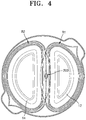
- FIG. 4 is a view conceptually showing a shape of a tray part 10 in the container for retort food according to the present disclosure
- FIG. 5 is a view conceptually showing a steam pressure applied to the tray part 10 in the container for retort food according to the present disclosure.
- the container for retort food is configured to include: a tray part 10 which has a predetermined area and a depth recessed in a downward direction and has a space open in an upward direction; and a flange part 20 which constitutes a periphery of an upper end of the tray part 10.
- the tray part 10 has a predetermined area, and is recessed in the downward direction and has a predetermined depth.
- the space inside the tray part 10 substantially constitutes a food input and storage space.
- the tray part 10 may have a generally circular shape and may be divided into a plurality of segments by an inner flange area 24 of the flange part 20, which will be described later. Accordingly, the tray part 10 may include a first tray 12 and a second tray 14.
- the first tray 12 and the second tray 14 may have arbitrary shapes, areas, and volumes.
- the inner flange area 24 crosses the vicinity of the central region of the container for retort food as described above, and thus, the first tray 12 and the second tray 14 may have relatively similar areas and volumes.
- the shape of each of the first tray 12 and the second tray 14 may have a shape close to a half circle.
- the flange part 20 constitutes a peripheral region of the upper end of the tray part 10.
- the flange part 20 may include an outer flange area 22 and an inner flange area 24.
- the outer flange area 22 may be a portion that constitutes an outer circumference of the container for retort food. As a result, the outer flange area 22 may form an appearance in the planar direction of the container for retort food. Preferably, the outer flange area 22 may have a generally circular ring shape.
- the inner flange area 24 may be a portion that divides the tray part 10 across the container for retort food.
- the inner flange area 24 may extend to cross the container for retort food approximately in the diameter direction.
- both ends of the inner flange area 24 may constitute a continuation with the inside of the outer flange area 22.
- the inner flange area 24 may have a straight line section or a curved line section having a relatively large curvature.
- the tray part 10 is divided into a plurality of tray elements independent from each other by the inner flange area 24. That is, the tray part 10 may be divided into the first tray 12 and the second tray 14 with the inner flange area 24 therebetween. Also, the inner flange area 24 and at least a portion of the outer flange area 22 are merged with each other to form one closed curve, and the closed curve may surround the first tray 12 and the second tray 14.
- the number of a plurality of trays constituting the tray part 10 may be an arbitrary value.
- the inner flange area 24 may be provided as a plurality of segments or have a plurality of branches.
- a ridge portion 100 and an exhaust hole 200 may be formed in the flange part 20.
- the ridge portion 100 is formed on the flange part 20, and is a component which is formed along the flange part 20, has a closed curve shape to surround the tray part 10, and protrudes a predetermined height in the upward direction.
- the ridge portion 100 may be configured by a recess which is formed to be recessed from the bottom surface of the flange part 20 in the upward direction so that a portion of the flange part 20 protrudes in the upward direction.
- the lid film When a lid film is attached to the container for retort food according to the present disclosure, the lid film may be attached to the ridge portion 100. That is, an upper end of the ridge portion 100 may function as an attachment surface to which the lid film is attached (thermally fused).
- the exhaust hole 200 may be a predetermined hole that vertically passes through at least a portion of the flange part 20.
- the exhaust hole 200 may be located in the inner flange area 24.
- the exhaust hole 200 may be formed at a central position of the container for retort food.
- the ridge portion 100 may include an inner ridge 110 formed in the inner flange area 24 and an outer ridge 120 formed in the outer flange area 22 and branching from the inner ridge 110.
- the inner ridge 110 and the outer ridge 120 have a concept indicating a portion of the ridge portion 100.
- the inner ridge 110 is formed on the inner flange area 24 and may have a straight line or curved line shape as extending along the inner flange area 24.
- the outer ridge 120 is formed on the outer flange area 22 and extends along the outer flange area 22.
- the outer ridge 120 may have a generally circular shape corresponding to the entire appearance of the container for retort food.
- the outer ridge 120 may branch from the inner ridge 110 into a plurality of segments.
- the inner ridge 110 may be understood as the place where two or more outer ridges 120 join.
- the outer ridge 120 may branch from the one inner ridge 110.
- the outer ridge 120 may include a first outer ridge 122 located on the outside of the first tray 12 and a second outer ridge 124 located on the outside of the second tray 14.
- the inner ridge 110 includes an intermediate ridge 130 connected to the outer ridge 120 and a branch ridge 140 located in the inside of the inner ridge 110 and connected to the intermediate ridge 130.
- the branch ridge 140 and the intermediate ridge 130 have a concept indicating a portion of the inner ridge 110.
- the intermediate ridge 130 is a portion which constitutes a portion of the inner ridge 110, and has one end connected to the outer ridge 120 and the other end connected to the branch ridge 140. As described later, the branch ridge 140 is located at a middle position of the inner ridge 110, and thus, the intermediate ridge 130 is provided on each of both sides of the branch ridge 140.
- the intermediate ridge 130 may include a first intermediate line 132 and a second intermediate line 134 which are disposed with the branch ridge 140 therebetween and are located at the respective sides of the branch ridge 140.
- a radius of curvature of the intermediate ridge 130 may be configured to be greater than a radius of curvature of the outer ridge 120.
- the intermediate ridge 130 may have a straight line shape or a shape close to a straight line.
- the branch ridge 140 is located in a peripheral region of the exhaust hole 200.
- the branch ridge 140 is located in a middle region of the inner ridge 110.
- the branch ridge 140 may have a branch structure which branches at one end into two or more segments and joins at the other end.
- the exhaust hole 200 may be located in a space between branches of the branch ridge 140.
- the branch ridge 140 may have a first branch line 142 and a second branch line 144.
- the first branch line 142 and the second branch line 144 branch from an end of the intermediate ridge 130 and are spaced predetermined distances from each other in the horizontal direction, and then may join at an end of the intermediate ridge 130.
- each of the first branch line 142 and the second branch line 144 extends after branching at a rear end of the first intermediate line 132, and then, when the first branch line 142 and the second branch line 144 arrive at a front end of the second intermediate line 134, the first branch line 142 and the second branch line 144 may join and be connected to the second intermediate line 134.
- the exhaust hole 200 may be located in a space V between the first branch line 142 and the second branch line 144. That is, the exhaust hole 200 is surrounded by the branch lines, the branch ridge 140 forms a closed curve surrounding the exhaust hole 200, and the exhaust hole 200 is located in the space V within the closed curve.
- the lid film bursts or peels at an arbitrary position due to a steam pressure generated in heated food. This occurs typically due to the high-pressure steam pressure, and open positions are also irregular while generating noises such as explosion sound.
- the container for retort food according to the present disclosure is provided with the exhaust hole 200 surrounded by the ridge portion 100.
- the steam may be discharged through the exhaust hole 200.
- a user does not need to peel off the lid film before the food is heated.
- the exhaust hole 200 is located at the central region of the container for retort food according to the present disclosure, and since the steam pressure is intensively applied to the ridge portion 100 around the exhaust hole 200 when the food is heated, the lid film around the exhaust hole 200 may be peeled off earlier. Thus, it is possible to prevent the lid film from being peeled off earlier from an unintended region.
- the exhaust hole 200 is located in the vicinity of the central region of the container for retort food, steam generated in each of trays may be exhausted relatively uniformly. Furthermore, in a steam discharge process, the steam passes through the exhaust hole 200 formed in the flange part 20 while staying in all regions around the exhaust hole 200, and then, the steam is exhausted downward. Thus, during the exhaust process, moisture of the food located around the exhaust hole 200 is not excessively eliminated. Thus, the quality of heated food may be improved.
- the position of the exhaust hole 200 is located around the central region of the container for retort food, a handle part 160 is located relatively far away from the steam exhaust position, and the discharge direction through the exhaust hole 200 is also the downward direction, and thus, when a user holds the handle part 160 of the heated container for retort food, the user is less likely to feel hot or get burned.
- the steam is discharged through the exhaust hole 200 having a relatively small size, moisture and pressure within the container is maintained relatively high, and thus, cooking for a steamed dish may be performed. Thus, the texture of heated food may be further improved.
- the tray part 10 has a generally circular shape, it is possible to prevent the steam pressure from being intensively applied to a specific outer region. Thus, it is possible to prevent the lid film from being unintentionally peeled off during the heating.
- the structure of the exhaust hole 200 surrounded by the branch ridge 140, the configuration in which the position of the exhaust hole 200 is located at the central region of the container for retort food, and the structure of the ridge portion 100 surrounding the tray part 10 in the closed curve shape may provide following effects.
- the lid film of the container for retort food according to the present disclosure may not be easily peeled off under sterilization conditions (for example, the retort food is exposed to pressurized heat at 70 to 120°C for 30 minute to 120 minutes).
- the lid film in the mid-region of the container for retort food is peeled earlier, and thus, when peeling off the lid film, a user may detach and peel off instantly while holding one side portion thereof.
- the user's convenience may be enhanced.
- the ridge portion 100 in the container for retort food according to the present disclosure has a closed curve shape that surrounds each of the trays.
- the food stored in each of the trays may be individually sealed, and the stored foods may be prevented from being mixed with each other.
- it may be used for retort food stored at room temperature in addition to a frozen food.
- the container for retort food according to the present disclosure described above have been confirmed through an experiment performed under actual mass-production conditions. For example, when a retort food sterilization process was performed after a container for retort food, in which the shape according to FIG. 1 is reflected, was filled with a food and sealed with a lid film, the lid film including a mid-lid film was not peeled off at all. Also, when cooked for a suitable time (2 minutes) in a commercialized microwave oven, only the lid film located in the middle region of the container for retort food was peeled off, and a steam discharge function was operated.
- At least one of the first branch line 142 and the second branch line 144 may have a first tip end 150 sharply protruding toward the tray part 10 adjacent thereto.
- the meaning of protruding sharply is not necessarily limited to the meaning that slopes of tangent lines to the ridge portion 100 have discontinuity. That is, according to one example, the case having a configuration, in which the magnitudes of the slopes of the tangent lines are continuous but change relatively rapidly compared to other regions, may also be included in the first tip end 150.
- the steam pressure may be intensively applied to the first tip end 150.
- the lid film located in the first tip end 150 may be peeled off from the ridge portion 100 earlier.
- the horizontal widths of the first branch line 142 and the second branch line 144 may be less than widths of the other regions of the ridge portion 100.
- a width D1 of each of the first branch line 142 and the second branch line 144 may be less than a width D2 of the intermediate ridge 130.
- the attachment widths of the lid film attached on the first branch line 142 and the second branch line 144 may be less than the attachment widths of the lid film attached on the other regions of the ridge portion 100.
- the radius of curvature of the intermediate ridge 130 may be configured to be greater than the radius of curvature of the outer ridge 120.
- the intermediate ridge 130 may have a straight line shape or a shape close to a straight line.
- the regions of the inner ridge 110 may be subjected to a greater steam pressure than the regions of the circular outer ridge 120.
- the inner ridge 110 is located in a space where the virtual ellipses constituting the tray part 10 overlap each other.
- the inner ridge 110 may be simultaneously subjected to the overlapped steam pressures which are applied from the tray part 10 on both sides.
- a steam pressure P1 applied to the inner ridge 110 may be greater than a steam pressure P2 applied to the outer ridge 120.
- the regions of the branch ridge 140 having the protruding three-dimensional structure may be intensively subjected to the steam pressure. That is, the branch ridge 140 may be subjected to the steam pressure more intensively than not only the outer ridge 120 but also the other regions of the inner ridge 110.
- the lid film attached on the region of the branch ridge 140 may be peeled off earlier than the lid film attached on the other regions. That is, as described above, the configuration about the first tip end 150, the configuration about the width of the branch line, and the configuration about the branch ridge 140 located between the intermediate ridge 130 having the larger radius of curvature may prevent the lid film from being unintentionally peeled off from the other regions of the ridge portion 100 earlier. Thus, exhaust effects by the exhaust hole 200 may be stably achieved.
- the flange part 20 may include the handle part 160, at least a portion of which extends outward in a radial direction of the container for retort food.
- the handle part 160 may be also provided on the opposite side in the radial direction of the container for retort food so that a user may easily hold the container for retort food with two hands.
- the handle part 160 may be located at a position spaced a predetermined distance from a horizontal line that crosses the inner flange area 24.
- the handle part 160 As the handle part 160 is provided, a user may easily hold, move, and use the container for retort food according to the present disclosure.
- the ridge portion 100 has a second tip end 170 which is located on the handle part 160 and protrudes in an outward direction of the container for retort food.
- the second tip end 170 has a shape protruding outward from the outer ridge 120 in a radial direction.
- the second tip end 170 may be located at a position which is further away from the exhaust hole 200 than the other regions of the outer ridge 120.
- the second tip end 170 As the second tip end 170 is provided, a user may easily peel off the lid film after the food is heated. Also, the second tip end 170 protrudes in an outer diameter direction of the container for retort food compared to the other regions and is thus subjected to relatively little steam pressure during a heating process. Thus, it is possible to prevent the lid film located on the handle part 160 from being unintentionally peeled off. If the lid film on the handle part 160 has been peeled off, steam is discharged through the corresponding region, and thus, a user is likely to feel hot or get burned when holding the handle part 160. However, such a limitation may be prevented because the present disclosure has the second tip end 170 described above to prevent the lid film on the handle part 160 from unintentionally being peeled off. Furthermore, since the middle region of the lid film is peeled off earlier during a heating process by a microwave oven as described above, the entire lid film may be peeled off instantly by using the second tip end 170 on one side.
- a stacking stepped portion 180 may be formed in the outer circumferential surface of the tray part 10.
- the stacking may be easily performed.
Landscapes
- Engineering & Computer Science (AREA)
- Mechanical Engineering (AREA)
- Ceramic Engineering (AREA)
- Life Sciences & Earth Sciences (AREA)
- Food Science & Technology (AREA)
- Package Specialized In Special Use (AREA)
- Packages (AREA)
Applications Claiming Priority (2)
| Application Number | Priority Date | Filing Date | Title |
|---|---|---|---|
| KR1020190010072A KR101982212B1 (ko) | 2019-01-25 | 2019-01-25 | 레토르트 식품용 용기 |
| PCT/KR2020/001210 WO2020153806A1 (fr) | 2019-01-25 | 2020-01-23 | Récipient pour aliment stérilisable en autoclave |
Publications (3)
| Publication Number | Publication Date |
|---|---|
| EP3915899A1 true EP3915899A1 (fr) | 2021-12-01 |
| EP3915899A4 EP3915899A4 (fr) | 2022-10-19 |
| EP3915899B1 EP3915899B1 (fr) | 2025-04-23 |
Family
ID=67775412
Family Applications (1)
| Application Number | Title | Priority Date | Filing Date |
|---|---|---|---|
| EP20745834.0A Active EP3915899B1 (fr) | 2019-01-25 | 2020-01-23 | Récipient pour aliment stérilisable en autoclave |
Country Status (5)
| Country | Link |
|---|---|
| US (1) | US12134509B2 (fr) |
| EP (1) | EP3915899B1 (fr) |
| KR (1) | KR101982212B1 (fr) |
| CN (1) | CN113348136B (fr) |
| WO (1) | WO2020153806A1 (fr) |
Families Citing this family (2)
| Publication number | Priority date | Publication date | Assignee | Title |
|---|---|---|---|---|
| KR101982212B1 (ko) | 2019-01-25 | 2019-08-28 | 씨제이제일제당 주식회사 | 레토르트 식품용 용기 |
| USD986052S1 (en) * | 2020-12-29 | 2023-05-16 | Blue Buffalo Enterprises, Inc. | Packaging container |
Family Cites Families (28)
| Publication number | Priority date | Publication date | Assignee | Title |
|---|---|---|---|---|
| US3539071A (en) * | 1968-10-09 | 1970-11-10 | Owens Illinois Inc | Packaging structure |
| US3654076A (en) * | 1969-09-29 | 1972-04-04 | Keyes Fibre Co | Nested packaging trays produced by a rotary pulp molding machine having different sets of molding dies |
| JPH0825583B2 (ja) * | 1986-03-27 | 1996-03-13 | ハウス食品株式会社 | 加熱調理用密封容器 |
| JPH0222728U (fr) * | 1988-07-27 | 1990-02-15 | ||
| JPH0733174Y2 (ja) | 1990-06-15 | 1995-07-31 | 株式会社ケンウッド | デジタルデータのピーク検出・読み出し回路 |
| JP2974232B2 (ja) * | 1993-07-07 | 1999-11-10 | 大塚化学株式会社 | 容 器 |
| JP4288631B2 (ja) * | 1999-03-26 | 2009-07-01 | リスパック株式会社 | 包装用容器 |
| KR100437730B1 (ko) | 2002-04-30 | 2004-06-30 | 한국항공우주산업 주식회사 | 랜딩 기어의 동력 테스트 장치 |
| JP4093813B2 (ja) * | 2002-07-26 | 2008-06-04 | 東洋アルミエコープロダクツ株式会社 | 部分加熱用容器 |
| KR20050051490A (ko) * | 2003-11-27 | 2005-06-01 | 주식회사 두산 | 통기구조가 개선된 발효식품 포장용기 |
| JP2007045488A (ja) | 2005-08-11 | 2007-02-22 | Dainippon Printing Co Ltd | 食品包装容器 |
| JP4888644B2 (ja) * | 2006-05-19 | 2012-02-29 | 東洋製罐株式会社 | 電子レンジ調理用包装体 |
| CN101583546B (zh) | 2006-11-02 | 2011-06-22 | 立花容器株式会社 | 包装体和容器 |
| JP4924613B2 (ja) * | 2006-11-10 | 2012-04-25 | 東洋製罐株式会社 | 電子レンジ調理用包装体 |
| JP3144711U (ja) * | 2008-06-27 | 2008-09-11 | 有限会社オールウエイズ | 電子レンジ用食品容器 |
| KR200465209Y1 (ko) | 2008-11-24 | 2013-02-07 | 씨제이제일제당 (주) | 증기 배출 용기 |
| JP3157394U (ja) | 2009-11-09 | 2010-02-18 | 株式会社生駒化学工業 | 密閉包装容器の蓋体および密閉包装容器 |
| KR200452037Y1 (ko) | 2010-10-20 | 2011-01-26 | 임상만 | 내부압력 해제기능을 갖춘 음식물 보관용기용 밀폐뚜껑 |
| JP5846810B2 (ja) * | 2011-08-29 | 2016-01-20 | 株式会社ディスペンパックジャパン | 分配包装体 |
| CN110329666B (zh) * | 2014-03-28 | 2021-06-04 | 京洛株式会社 | 微波炉用容器以及微波炉用包装体 |
| JP6500269B2 (ja) | 2014-03-31 | 2019-04-17 | キョーラク株式会社 | 電子レンジ用包装体 |
| JP6550707B2 (ja) | 2014-09-30 | 2019-07-31 | キョーラク株式会社 | 電子レンジ用容器 |
| KR101536268B1 (ko) * | 2015-01-22 | 2015-07-13 | 정희국 | 음식물 조리용 용기의 함몰 방지구조 |
| JP6693124B2 (ja) * | 2015-12-28 | 2020-05-13 | 大日本印刷株式会社 | 液状物収容容器 |
| KR20190010072A (ko) | 2017-07-20 | 2019-01-30 | 엘지디스플레이 주식회사 | 투명표시장치 및 그 구동방법 |
| CN207890351U (zh) * | 2018-01-29 | 2018-09-21 | 重庆凯年食品有限公司 | 自热式香肠包装盒 |
| KR20180003054U (ko) * | 2018-10-12 | 2018-10-23 | 씨제이제일제당 (주) | 포장 용기 |
| KR101982212B1 (ko) * | 2019-01-25 | 2019-08-28 | 씨제이제일제당 주식회사 | 레토르트 식품용 용기 |
-
2019
- 2019-01-25 KR KR1020190010072A patent/KR101982212B1/ko active Active
-
2020
- 2020-01-23 CN CN202080010726.7A patent/CN113348136B/zh active Active
- 2020-01-23 EP EP20745834.0A patent/EP3915899B1/fr active Active
- 2020-01-23 US US17/425,612 patent/US12134509B2/en active Active
- 2020-01-23 WO PCT/KR2020/001210 patent/WO2020153806A1/fr not_active Ceased
Also Published As
| Publication number | Publication date |
|---|---|
| WO2020153806A1 (fr) | 2020-07-30 |
| EP3915899B1 (fr) | 2025-04-23 |
| EP3915899A4 (fr) | 2022-10-19 |
| CN113348136A (zh) | 2021-09-03 |
| US20220097947A1 (en) | 2022-03-31 |
| CN113348136B (zh) | 2023-02-21 |
| US12134509B2 (en) | 2024-11-05 |
| KR101982212B1 (ko) | 2019-08-28 |
Similar Documents
| Publication | Publication Date | Title |
|---|---|---|
| CA2721885C (fr) | Conditionnement alimentaire multielements pour four a micro- ondes | |
| US4916280A (en) | Food package adapted particularly for microwave heating | |
| US5247149A (en) | Method and appliance for cooking a frozen pizza pie with microwave energy | |
| US7781036B2 (en) | Pouch for steaming vegetables | |
| US20090042705A1 (en) | Multi-Compartment Microwaveable Food Container | |
| JP2004520901A (ja) | 電子レンジ用の調理トレイとスリーブとのアセンブリ | |
| US20090014443A1 (en) | Container and system for cooking foods | |
| EP2852539B1 (fr) | Emballage alimentaire | |
| US12134509B2 (en) | Container for retort food | |
| CA2638530A1 (fr) | Contenant alimentaire a plusieurs compartiments pouvant etre chauffe au four a micro-ondes | |
| KR102218016B1 (ko) | 레토르트 식품용 용기 | |
| EP2157031A1 (fr) | Emballage alimentaire à énergie différentielle pouvant passer au micro-onde | |
| JP2001287776A (ja) | 電子レンジ対応の包装容器 | |
| JP6655750B1 (ja) | カップ食品及びカップ食品容器 | |
| JP2021065752A (ja) | 反転を含むマイクロ波加熱用装置及びマイクロ波加熱方法 | |
| KR200465209Y1 (ko) | 증기 배출 용기 | |
| JP3159788U (ja) | 包装容器 | |
| JP2005328731A (ja) | 包装食品と食品の包装調理方法 | |
| KR102531353B1 (ko) | 냉동피자 판매용기 | |
| JP3650652B2 (ja) | 保存食品の加熱式容器 | |
| KR200431742Y1 (ko) | 서셉터 패키징을 이용한 군만두 제품 포장재 | |
| JP2017013885A (ja) | パッケージ | |
| CA2118159A1 (fr) | Preparation de crevettes au four a micro-ondes, ainsi que methode et appareil de cuisson a la vapeur | |
| JP2000203660A (ja) | 電子レンジ用食品容器 | |
| KR20170032041A (ko) | 전자레인지용 조리용기의 뚜껑 |
Legal Events
| Date | Code | Title | Description |
|---|---|---|---|
| STAA | Information on the status of an ep patent application or granted ep patent |
Free format text: STATUS: THE INTERNATIONAL PUBLICATION HAS BEEN MADE |
|
| PUAI | Public reference made under article 153(3) epc to a published international application that has entered the european phase |
Free format text: ORIGINAL CODE: 0009012 |
|
| STAA | Information on the status of an ep patent application or granted ep patent |
Free format text: STATUS: REQUEST FOR EXAMINATION WAS MADE |
|
| 17P | Request for examination filed |
Effective date: 20210722 |
|
| AK | Designated contracting states |
Kind code of ref document: A1 Designated state(s): AL AT BE BG CH CY CZ DE DK EE ES FI FR GB GR HR HU IE IS IT LI LT LU LV MC MK MT NL NO PL PT RO RS SE SI SK SM TR |
|
| DAV | Request for validation of the european patent (deleted) | ||
| DAX | Request for extension of the european patent (deleted) | ||
| A4 | Supplementary search report drawn up and despatched |
Effective date: 20220916 |
|
| RIC1 | Information provided on ipc code assigned before grant |
Ipc: B65D 71/40 20060101ALI20220912BHEP Ipc: B65D 51/16 20060101ALI20220912BHEP Ipc: B65D 1/36 20060101ALI20220912BHEP Ipc: B65D 81/34 20060101ALI20220912BHEP Ipc: B65D 77/20 20060101AFI20220912BHEP |
|
| P01 | Opt-out of the competence of the unified patent court (upc) registered |
Effective date: 20230606 |
|
| GRAP | Despatch of communication of intention to grant a patent |
Free format text: ORIGINAL CODE: EPIDOSNIGR1 |
|
| STAA | Information on the status of an ep patent application or granted ep patent |
Free format text: STATUS: GRANT OF PATENT IS INTENDED |
|
| INTG | Intention to grant announced |
Effective date: 20241118 |
|
| GRAS | Grant fee paid |
Free format text: ORIGINAL CODE: EPIDOSNIGR3 |
|
| GRAA | (expected) grant |
Free format text: ORIGINAL CODE: 0009210 |
|
| STAA | Information on the status of an ep patent application or granted ep patent |
Free format text: STATUS: THE PATENT HAS BEEN GRANTED |
|
| AK | Designated contracting states |
Kind code of ref document: B1 Designated state(s): AL AT BE BG CH CY CZ DE DK EE ES FI FR GB GR HR HU IE IS IT LI LT LU LV MC MK MT NL NO PL PT RO RS SE SI SK SM TR |
|
| REG | Reference to a national code |
Ref country code: GB Ref legal event code: FG4D |
|
| REG | Reference to a national code |
Ref country code: CH Ref legal event code: EP |
|
| REG | Reference to a national code |
Ref country code: DE Ref legal event code: R096 Ref document number: 602020049959 Country of ref document: DE |
|
| REG | Reference to a national code |
Ref country code: IE Ref legal event code: FG4D |
|
| REG | Reference to a national code |
Ref country code: NL Ref legal event code: MP Effective date: 20250423 |
|
| PG25 | Lapsed in a contracting state [announced via postgrant information from national office to epo] |
Ref country code: NL Free format text: LAPSE BECAUSE OF FAILURE TO SUBMIT A TRANSLATION OF THE DESCRIPTION OR TO PAY THE FEE WITHIN THE PRESCRIBED TIME-LIMIT Effective date: 20250423 |
|
| REG | Reference to a national code |
Ref country code: AT Ref legal event code: MK05 Ref document number: 1787588 Country of ref document: AT Kind code of ref document: T Effective date: 20250423 |
|
| PG25 | Lapsed in a contracting state [announced via postgrant information from national office to epo] |
Ref country code: FI Free format text: LAPSE BECAUSE OF FAILURE TO SUBMIT A TRANSLATION OF THE DESCRIPTION OR TO PAY THE FEE WITHIN THE PRESCRIBED TIME-LIMIT Effective date: 20250423 Ref country code: ES Free format text: LAPSE BECAUSE OF FAILURE TO SUBMIT A TRANSLATION OF THE DESCRIPTION OR TO PAY THE FEE WITHIN THE PRESCRIBED TIME-LIMIT Effective date: 20250423 Ref country code: PT Free format text: LAPSE BECAUSE OF FAILURE TO SUBMIT A TRANSLATION OF THE DESCRIPTION OR TO PAY THE FEE WITHIN THE PRESCRIBED TIME-LIMIT Effective date: 20250825 |
|
| REG | Reference to a national code |
Ref country code: LT Ref legal event code: MG9D |
|
| PG25 | Lapsed in a contracting state [announced via postgrant information from national office to epo] |
Ref country code: NO Free format text: LAPSE BECAUSE OF FAILURE TO SUBMIT A TRANSLATION OF THE DESCRIPTION OR TO PAY THE FEE WITHIN THE PRESCRIBED TIME-LIMIT Effective date: 20250723 Ref country code: GR Free format text: LAPSE BECAUSE OF FAILURE TO SUBMIT A TRANSLATION OF THE DESCRIPTION OR TO PAY THE FEE WITHIN THE PRESCRIBED TIME-LIMIT Effective date: 20250724 |
|
| PG25 | Lapsed in a contracting state [announced via postgrant information from national office to epo] |
Ref country code: PL Free format text: LAPSE BECAUSE OF FAILURE TO SUBMIT A TRANSLATION OF THE DESCRIPTION OR TO PAY THE FEE WITHIN THE PRESCRIBED TIME-LIMIT Effective date: 20250423 |
|
| PG25 | Lapsed in a contracting state [announced via postgrant information from national office to epo] |
Ref country code: BG Free format text: LAPSE BECAUSE OF FAILURE TO SUBMIT A TRANSLATION OF THE DESCRIPTION OR TO PAY THE FEE WITHIN THE PRESCRIBED TIME-LIMIT Effective date: 20250423 |
|
| PG25 | Lapsed in a contracting state [announced via postgrant information from national office to epo] |
Ref country code: HR Free format text: LAPSE BECAUSE OF FAILURE TO SUBMIT A TRANSLATION OF THE DESCRIPTION OR TO PAY THE FEE WITHIN THE PRESCRIBED TIME-LIMIT Effective date: 20250423 |
|
| PG25 | Lapsed in a contracting state [announced via postgrant information from national office to epo] |
Ref country code: AT Free format text: LAPSE BECAUSE OF FAILURE TO SUBMIT A TRANSLATION OF THE DESCRIPTION OR TO PAY THE FEE WITHIN THE PRESCRIBED TIME-LIMIT Effective date: 20250423 |
|
| PG25 | Lapsed in a contracting state [announced via postgrant information from national office to epo] |
Ref country code: RS Free format text: LAPSE BECAUSE OF FAILURE TO SUBMIT A TRANSLATION OF THE DESCRIPTION OR TO PAY THE FEE WITHIN THE PRESCRIBED TIME-LIMIT Effective date: 20250723 |
|
| PG25 | Lapsed in a contracting state [announced via postgrant information from national office to epo] |
Ref country code: IS Free format text: LAPSE BECAUSE OF FAILURE TO SUBMIT A TRANSLATION OF THE DESCRIPTION OR TO PAY THE FEE WITHIN THE PRESCRIBED TIME-LIMIT Effective date: 20250823 |
|
| PG25 | Lapsed in a contracting state [announced via postgrant information from national office to epo] |
Ref country code: LV Free format text: LAPSE BECAUSE OF FAILURE TO SUBMIT A TRANSLATION OF THE DESCRIPTION OR TO PAY THE FEE WITHIN THE PRESCRIBED TIME-LIMIT Effective date: 20250423 |
|
| PGFP | Annual fee paid to national office [announced via postgrant information from national office to epo] |
Ref country code: GB Payment date: 20251120 Year of fee payment: 7 |
|
| PG25 | Lapsed in a contracting state [announced via postgrant information from national office to epo] |
Ref country code: SM Free format text: LAPSE BECAUSE OF FAILURE TO SUBMIT A TRANSLATION OF THE DESCRIPTION OR TO PAY THE FEE WITHIN THE PRESCRIBED TIME-LIMIT Effective date: 20250423 Ref country code: DK Free format text: LAPSE BECAUSE OF FAILURE TO SUBMIT A TRANSLATION OF THE DESCRIPTION OR TO PAY THE FEE WITHIN THE PRESCRIBED TIME-LIMIT Effective date: 20250423 |
|
| PGFP | Annual fee paid to national office [announced via postgrant information from national office to epo] |
Ref country code: FR Payment date: 20251125 Year of fee payment: 7 |
|
| PG25 | Lapsed in a contracting state [announced via postgrant information from national office to epo] |
Ref country code: CZ Free format text: LAPSE BECAUSE OF FAILURE TO SUBMIT A TRANSLATION OF THE DESCRIPTION OR TO PAY THE FEE WITHIN THE PRESCRIBED TIME-LIMIT Effective date: 20250423 |
|
| PG25 | Lapsed in a contracting state [announced via postgrant information from national office to epo] |
Ref country code: EE Free format text: LAPSE BECAUSE OF FAILURE TO SUBMIT A TRANSLATION OF THE DESCRIPTION OR TO PAY THE FEE WITHIN THE PRESCRIBED TIME-LIMIT Effective date: 20250423 |
|
| REG | Reference to a national code |
Ref country code: DE Ref legal event code: R097 Ref document number: 602020049959 Country of ref document: DE |
|
| PG25 | Lapsed in a contracting state [announced via postgrant information from national office to epo] |
Ref country code: SK Free format text: LAPSE BECAUSE OF FAILURE TO SUBMIT A TRANSLATION OF THE DESCRIPTION OR TO PAY THE FEE WITHIN THE PRESCRIBED TIME-LIMIT Effective date: 20250423 Ref country code: RO Free format text: LAPSE BECAUSE OF FAILURE TO SUBMIT A TRANSLATION OF THE DESCRIPTION OR TO PAY THE FEE WITHIN THE PRESCRIBED TIME-LIMIT Effective date: 20250423 |
|
| PG25 | Lapsed in a contracting state [announced via postgrant information from national office to epo] |
Ref country code: IT Free format text: LAPSE BECAUSE OF FAILURE TO SUBMIT A TRANSLATION OF THE DESCRIPTION OR TO PAY THE FEE WITHIN THE PRESCRIBED TIME-LIMIT Effective date: 20250423 |
|
| PLBE | No opposition filed within time limit |
Free format text: ORIGINAL CODE: 0009261 |
|
| STAA | Information on the status of an ep patent application or granted ep patent |
Free format text: STATUS: NO OPPOSITION FILED WITHIN TIME LIMIT |
|
| REG | Reference to a national code |
Ref country code: CH Ref legal event code: L10 Free format text: ST27 STATUS EVENT CODE: U-0-0-L10-L00 (AS PROVIDED BY THE NATIONAL OFFICE) Effective date: 20260304 |
|
| 26N | No opposition filed |
Effective date: 20260126 |
|
| PGFP | Annual fee paid to national office [announced via postgrant information from national office to epo] |
Ref country code: DE Payment date: 20251120 Year of fee payment: 7 |