EP3921919B1 - Magnetblechstapel, verfahren zur fertigung eines magnetblechstapels und elektrische maschine - Google Patents
Magnetblechstapel, verfahren zur fertigung eines magnetblechstapels und elektrische maschine Download PDFInfo
- Publication number
- EP3921919B1 EP3921919B1 EP20721461.0A EP20721461A EP3921919B1 EP 3921919 B1 EP3921919 B1 EP 3921919B1 EP 20721461 A EP20721461 A EP 20721461A EP 3921919 B1 EP3921919 B1 EP 3921919B1
- Authority
- EP
- European Patent Office
- Prior art keywords
- sheet stack
- magnetic sheet
- magnetic
- magnetic sheets
- micrometres
- Prior art date
- Legal status (The legal status is an assumption and is not a legal conclusion. Google has not performed a legal analysis and makes no representation as to the accuracy of the status listed.)
- Active
Links
Images

Classifications
-
- H—ELECTRICITY
- H01—ELECTRIC ELEMENTS
- H01F—MAGNETS; INDUCTANCES; TRANSFORMERS; SELECTION OF MATERIALS FOR THEIR MAGNETIC PROPERTIES
- H01F27/00—Details of transformers or inductances, in general
- H01F27/28—Coils; Windings; Conductive connections
- H01F27/2804—Printed windings
-
- H—ELECTRICITY
- H02—GENERATION; CONVERSION OR DISTRIBUTION OF ELECTRIC POWER
- H02K—DYNAMO-ELECTRIC MACHINES
- H02K1/00—Details of the magnetic circuit
- H02K1/04—Details of the magnetic circuit characterised by the material used for insulating the magnetic circuit or parts thereof
-
- H—ELECTRICITY
- H01—ELECTRIC ELEMENTS
- H01F—MAGNETS; INDUCTANCES; TRANSFORMERS; SELECTION OF MATERIALS FOR THEIR MAGNETIC PROPERTIES
- H01F17/00—Fixed inductances of the signal type
- H01F17/0006—Printed inductances
- H01F17/0013—Printed inductances with stacked layers
-
- H—ELECTRICITY
- H02—GENERATION; CONVERSION OR DISTRIBUTION OF ELECTRIC POWER
- H02K—DYNAMO-ELECTRIC MACHINES
- H02K15/00—Processes or apparatus specially adapted for manufacturing, assembling, maintaining or repairing of dynamo-electric machines
- H02K15/02—Processes or apparatus specially adapted for manufacturing, assembling, maintaining or repairing of dynamo-electric machines of stator or rotor bodies
-
- H—ELECTRICITY
- H01—ELECTRIC ELEMENTS
- H01F—MAGNETS; INDUCTANCES; TRANSFORMERS; SELECTION OF MATERIALS FOR THEIR MAGNETIC PROPERTIES
- H01F27/00—Details of transformers or inductances, in general
- H01F27/28—Coils; Windings; Conductive connections
- H01F27/2804—Printed windings
- H01F2027/2809—Printed windings on stacked layers
-
- H—ELECTRICITY
- H02—GENERATION; CONVERSION OR DISTRIBUTION OF ELECTRIC POWER
- H02K—DYNAMO-ELECTRIC MACHINES
- H02K2213/00—Specific aspects, not otherwise provided for and not covered by codes H02K2201/00 - H02K2211/00
- H02K2213/03—Machines characterised by numerical values, ranges, mathematical expressions or similar information
Definitions
- the invention relates to a stack of magnetic sheets, a method for manufacturing a stack of magnetic sheets and an electrical machine.
- Such magnetic sheet stacks are regularly produced by introducing thin, electrically insulating (polymer) layers between the individual magnetic sheets of the magnetic sheet stack. With such insulating layers, the formation of eddy currents is to be suppressed and a sufficiently mechanically stable structure is to be ensured.
- the following documents already disclose various methods for manufacturing a stack of magnetic sheets using spacers: U.S. 2018/358868 A1 , WO 2011/101985 A1 , EP 3 255 758 A1 and WO 2019/008722 A1 .
- the object of the invention is to specify a stack of magnetic sheets which is improved over the prior art and which, in particular, has a higher thermal stability. Furthermore, the object of the invention is to specify an improved method for manufacturing a stack of magnetic sheets and an improved electrical machine.
- This object of the invention is achieved with a stack of magnetic sheets having the features specified in claim 1 and with a method having the features specified in claim 8 and with an electrical machine having the features specified in claim 10 .
- the stack of magnetic laminations according to the invention is formed with a plurality of magnetic laminations which are electrically insulated from one another by being spaced apart from one another predominantly by a non-vanishing clear dimension.
- a spacing of the magnetic sheets predominantly with a non-vanishing clearance is to be understood as meaning that the magnetic sheets of the stack of magnetic sheets with their flat sides facing adjacent magnetic sheets do not rest with a predominant surface area on components located between the magnetic sheets, but rather the majority of the surface area of the flat sides with adjacent magnetic sheets includes a clearance greater than zero.
- the majority of the area is an area that exceeds half the area, preferably at least 90 percent of the area, particularly preferably at least 98 percent of the area.
- the sheet magnets are electrically insulated from one another as a result of their spacing with a predominantly clear dimension, without having to provide separate insulating materials in the solid aggregate state between the sheet magnets of the sheet magnet stack.
- a particularly high temperature stability is consequently made possible due to the possible omission of insulating materials.
- the magnetic sheets are advantageously electrically insulated from one another only by an intermediate layer of air, in particular of homogeneous thickness, as a result of their spacing over the majority of their flat extensions.
- the invention further insulation materials, such as organic insulating layers such as paints in particular, dispensable.
- a particularly high thermal load capacity of the magnetic sheet stack can be achieved.
- the distance between the magnetic sheets of the magnetic sheet stack, which can be set in a defined manner, also opens up further degrees of freedom in the design of the magnetic sheet stack.
- the magnetic sheets are spaced apart from one another by means of a plurality of intermediate spacers.
- a defined gap in particular an air gap
- the magnetic sheets can be cooled through the gaps with a cooling fluid, preferably by means of cooling air.
- the stack of magnetic sheets according to the invention has a particularly high mechanical stability due to the spacers provided.
- the spacers are formed with or from ceramics.
- Spacers formed with ceramics can advantageously be designed to be highly electrically insulating and at the same time mechanically high-strength, so that a particularly high electrical temperature load capacity is made possible.
- the spacer(s) is/are formed with aluminum oxide and/or zirconium oxide and/or magnesium oxide and/or yttrium oxide and/or boron nitride and/or yttrium aluminum garnet and/or silicon nitride and/or silicon dioxide. It is precisely the aforementioned materials that enable spacers with particularly strong electrically insulating and at the same time mechanically high-strength properties, so that a stack of magnetic sheets with a high temperature resistance can be realized.
- the spacers are formed with particles of electrically insulating material.
- particles of electrically insulating material in particular with particles in the micrometer range, it is easily possible to implement a defined air gap with a width of a fraction of a micrometer or a few micrometers to avoid the formation of eddy currents.
- the arrangement of such spacers is particularly easy, since only a sufficiently high density has to be achieved for reliable spacing of the magnetic sheets.
- precise positioning of the spacers on the magnetic sheets in the manner of controlled micromanipulation is not specifically required. Ceramic particles thus form spacers that are particularly easy to use in the distance range of a few micrometers that is relevant according to the invention.
- the concentration of particles can also be freely adjusted, so that the spacing of the magnetic sheets of the magnetic sheet stack can be freely adjusted and tailored.
- the particles in the stack of magnetic sheets are formed with ceramic particles.
- ceramic particles just a few micrometers in size form particularly hard and high-strength spacers, which allow high temperature stress.
- the particle or particles are preferably of essentially spherical design.
- a controlled spacing of magnetic sheets can be easily achieved with spherical particles, since with spherical particles a controlled orientation of these particles on magnetic sheets due to the isotropy of the spherical shape is not required.
- the particles have a substantially spherical shape.
- a substantially spherical shape means a shape whose radius varies within at most 20 percent in different directions in space. More preferably the radius varies within at most 10 percent and ideally within at most 5 percent.
- the particles particularly preferably have a non-splintering and/or non-splintered and/or non-fibrous and/or non-platelike shape.
- the particles have a diameter of at most 300 microns and preferably at most 100 microns. Ideally, the particles have a diameter of at most 50 microns.
- the diameters of the particles have a size distribution that is monomodal or, at least approximately, Gaussian distributed and/or has a mean value of at least 0.5 micrometers and/or at most 20 micrometers, preferably at least one micrometer and/or at most 6 micrometers, especially preferably at least 2 microns and/or at most 4 microns.
- a diameter of a particle within the meaning of the present invention is preferably to be understood as meaning a largest diameter of the particle, ie the largest dimension of the particle in one spatial direction.
- a diameter of a particle within the meaning of this invention is to be understood as meaning a smallest diameter of the particle, ie a smallest dimension of the particle along a spatial direction.
- the diameters of the particles are distributed with a distribution function having a standard deviation of at most 5 microns, suitably at most 3 microns and ideally at most 1 micron.
- the suspension is deposited on one or more magnetic sheets in the method, after which the magnetic sheets are stacked.
- it is consequently not necessary to micro-position separate spacers individually. Rather, it is sufficient to keep the spacers in the form of particles formed with electrically insulating material in a suspension and to apply them to the magnetic sheets as a suspension.
- the suspension can optionally contain binders which to a certain extent stick the particles to the magnetic sheets after deposition.
- the particles are spherical particles and preferably ceramic particles as described above.
- mechanical stability of the stack of magnetic sheets is very easily ensured by means of ceramic particles.
- the suspension is deposited by spraying and/or printing it and/or dipping the magnetic sheet(s) into the suspension.
- the magnetic sheets are expediently pressed or packaged together during or after they are stacked.
- the particles are held between the magnetic sheets in a non-positive manner and possibly also in a form-fitting manner in such a way that the particles are mechanically extremely stable between the magnetic sheets.
- the electric machine according to the invention is in particular an electric motor and/or an electric generator and has a stack of magnetic sheets according to the invention as described above, in particular produced using a method according to the invention as described above.
- the electrical machine preferably has a stator and/or a rotor, each with a stack of magnetic sheets according to the invention.
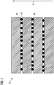
- the stack of magnetic laminations 10 comprises, in a manner known per se, a plurality of magnetic laminations 20 which are essentially in the form of planar flat parts with flat sides parallel to one another.
- the magnetic sheets 20 are spaced from each other by means of ceramic particles 30 which are located between the magnetic sheets 20 and are in contact with them.
- the ceramic particles 30 each have an almost perfectly spherical shape and a diameter of 40 micrometers.
- the ceramic particles 30 have a very homogeneous size distribution among themselves, ie the diameters of the ceramic particles are approximately Gaussian with a mean value of 3 micrometers and a standard deviation of 1.5 micrometers.
- ceramic particles which have a diameter of more than 5 micrometers and less than one micrometer are additionally filtered out.
- the ceramic particles 30 thus function to a certain extent as spacers between two adjacent magnetic sheets 20 and hold them the magnetic sheets are spaced at an average distance of about 2.5 microns from each other, since the ceramic particles are easily pressed into the metal surfaces during stack compression.
- the ceramic particles can also have a monomodal size distribution.
- the ceramic particles 30 are formed from aluminum oxide. In other exemplary embodiments that are not specifically illustrated, the ceramic particles 30 are formed alternatively or additionally with or from zirconium oxide and/or magnesium oxide and/or yttrium oxide and/or boron nitride and/or yttrium aluminum garnet and/or silicon nitride and/or silicon dioxide.
- the magnetic sheets 20 are punched or manufactured in some other way, for example by means of screen printing and/or stencil printing and subsequent sintering.
- the ceramic particles 30 can then be introduced between the magnetic sheets 20 as follows: A suspension with the ceramic particles 30 is used for this purpose.
- a suspension with the ceramic particles 30 is used for this purpose.
- an aqueous suspension with the ceramic particles 30 is used.
- the ceramic particles 30 can be introduced by means of a suspension of the ceramic particles 30 in an organic solvent.
- Optional binders and dispersants are added to the suspension.
- the suspension with the ceramic particles 30 is applied to the magnetic sheets 20 by means of spraying or dipping or printing, after which the suspension is dried and cured as a subsequent process step.
- the hardening step can also be omitted.
- the magnetic sheets 20 are then stacked on top of one another and pressed together in the direction perpendicular to the flat sides of the magnetic sheets 20, i.e. in the stacking direction S.
- the individual ceramic particles 30 are mechanically pressed into the flat sides of the magnetic sheets 20 .
- the ceramic particles 30 also remain fixed to the flat sides of the magnetic sheets 20 via the binder acting as an adhesive. In this way, the ceramic particles 30 remain positively and non-positively fixed between the magnetic sheets 20 even under high operating loads.
- the magnetic sheets 20 can also be pressed in other ways in further exemplary embodiments that are not shown specifically.
- the electric machine 200 comprises a stator 210 and a rotor 220. Both the stator 210 and the rotor 220 of the electric machine are each formed with a stack of magnetic sheets 10 according to the invention produced according to the invention as described above.
Landscapes
- Engineering & Computer Science (AREA)
- Power Engineering (AREA)
- Manufacturing & Machinery (AREA)
- Microelectronics & Electronic Packaging (AREA)
- Laminated Bodies (AREA)
- Hard Magnetic Materials (AREA)
- Manufacturing Cores, Coils, And Magnets (AREA)
- Sheets, Magazines, And Separation Thereof (AREA)
Description
- Die Erfindung betrifft einen Magnetblechstapel, ein Verfahren zur Fertigung eines Magnetblechstapels und eine elektrische Maschine.
- Es ist bekannt, elektrischen Maschinen mit Rotoren und Statoren auszubilden, welche Magnetblechstapel umfassen.
- Regelmäßig werden solche Magnetblechstapel hergestellt, indem dünne, elektrisch isolierende (Polymer-)Lagen zwischen den einzelnen Magnetblechen des Magnetblechstapels eingebracht werden. Mit solchen isolierenden Lagen soll die Entstehung von Wirbelströmen unterdrückt werden und ein ausreichend mechanisch stabiler Aufbau gewährleistet werden. Die folgenden Dokumenten offenbaren bereits verschiedene Verfahren zur Fertigung eines Magnetblechstapels mittels Abstandhalter:
US 2018/358868 A1 ,WO 2011/101985 A1 ,EP 3 255 758 A1 undWO 2019/008722 A1 . - Jedoch begrenzt bei solchen Magnetblechstapeln eine thermische Belastung der Magnetbleche des Magnetblechstapels deren praktischen Einsatz.
- Es ist daher Aufgabe der Erfindung, einen gegenüber dem Stand der Technik verbesserten Magnetblechstapel anzugeben, welcher insbesondere eine höhere Temperaturbelastbarkeit aufweist. Ferner ist es Aufgabe der Erfindung, ein verbessertes Verfahren zur Fertigung eines Magnetblechstapels sowie eine verbesserte elektrische Maschine anzugeben.
- Diese Aufgabe der Erfindung wird mit einem Magnetblechstapel mit den in Anspruch 1 angegebenen Merkmalen sowie mit einem Verfahren mit den in Anspruch 8 angegebenen Merkmalen sowie mit einer elektrischen Maschine mit den in Anspruch 10 angegebenen Merkmalen gelöst.
- Bevorzugte Weiterbildungen der Erfindung sind in den zugehörigen Unteransprüchen, der nachfolgenden Beschreibung und der Zeichnung angegeben.
- Der erfindungsgemäße Magnetblechstapel ist mit einer Mehrzahl von Magnetblechen gebildet, welche voneinander elektrisch isoliert sind, indem sie voneinander überwiegend mit nichtverschwindendem lichten Maß beabstandet sind.
- Unter einer überwiegend mit nichtverschwindendem lichten Maß bestehenden Beabstandung der Magnetbleche ist zu verstehen, dass die Magnetbleche des Magnetblechstapels mit ihren, benachbarten Magnetblechen zugewandten, Flachseiten mit einem überwiegenden Flächenanteil nicht an zwischen den Magnetblechen befindlichen Bauteilen anliegen, sondern der überwiegende Flächenanteil der Flachseiten mit benachbarten Magnetblechen ein lichtes Maß größer als Null einschließt. Zweckmäßig ist der überwiegende Flächenanteil ein den halben Flächenanteil übersteigender Flächenanteil, vorzugsweise ein zumindest 90-prozentiger Flächenanteil, besonders bevorzugt ein mindestens 98-prozentiger Flächenanteil.
- Bei dem erfindungsgemäßen Magnetblechstapel sind die Magnetbleche infolge ihrer Beabstandung mit überwiegend lichtem Maß voneinander elektrisch isoliert, ohne dass eigens Isolierstoffe im festen Aggregatzustand zwischen den Magnetblechen des Magnetblechstapels vorgesehen sein müssen. Bei dem erfindungsgemäßen Magnetblechstapel ist folglich aufgrund des möglichen Verzichts von Isolationsmaterialien eine besonders hohe Temperaturstabilität ermöglicht. Zweckmäßig befindet sich über den überwiegenden Teil der flächigen Erstreckung der Magnetbleche zwischen diesen lediglich eine Gasschicht, insbesondere eine Luftschicht. Vorteilhaft sind bei dem erfindungsgemäßen Magnetblechstapel die Magnetbleche infolge ihrer Beabstandung über den überwiegenden Teil ihrer flächigen Erstreckungen lediglich durch je eine zwischenliegende Luftschicht insbesondere homogener Dicke voneinander elektrisch isoliert. Daher sind bei dem Magnetblechstapel gemäß der Erfindung weitere Isolationsmaterialien, etwa organische Isolierlagen wie insbesondere Lacke, verzichtbar. Somit ist erfindungsgemäß eine besonders hohe Temperaturbelastbarkeit des Magnetblechstapels erzielbar. Durch den definiert einstellbaren Abstand der Magnetbleche des Magnetblechstapels sind zudem weitere Freiheitsgrade im Design des Magnetblechstapels eröffnet.
- Bei dem erfindungsgemäßen Magnetblechstapel sind die Magnetbleche mittels mehrerer zwischenliegender Abstandshalter voneinander beabstandet.
- Mittels der in der Erfindung vorgesehenen Abstandshalter zwischen zwei Magnetblechen ist zum einen ein definierter Spalt, insbesondere Luftspalt, zwischen den Magnetblechen realisierbar. Folglich sind die Magnetbleche durch die Spalte mit einem Kühlfluid, vorzugsweise mittels Kühlluft kühlbar. Zugleich weist der erfindungsgemäße Magnetblechstapel aufgrund der vorgesehenen Abstandshalter eine besonders hohe mechanische Stabilität auf.
- Bei dem erfindungsgemäßen Magnetblechstapel sind die Abstandshalter mit oder aus Keramik gebildet. Mit Keramik gebildete Abstandshalter lassen sich vorteilhaft hochgradig elektrisch isolierend und gleichzeitig mechanisch hochfest ausbilden, sodass eine besonders hohe elektrische Temperaturbelastbarkeit ermöglicht ist.
- In einer bevorzugten Weiterbildung des erfindungsgemäßen Magnetblechstapels ist oder sind der oder die Abstandshalter mit Aluminiumoxid und/oder Zirkonoxid und/oder Magnesiumoxid und/oder Yttriumoxid und/oder Bornitrid und/oder Yttrium-Aluminium-Granat und/oder Siliziumnitrid und/oder Siliziumdioxid gebildet. Gerade die vorgenannten Materalien ermöglichen Abstandshalter mit besonders stark elektrisch isolierenden und gleichzeitig mechanisch hochfesten Eigenschaften, sodass ein Magnetblechstapel mit einer hohen Temperaturbelastbarkeit realisierbar ist.
- Bei dem erfindungsgemäßen Magnetblechstapel sind die Abstandshalter mit Partikeln elektrisch isolierenden Materials gebildet. Mit Partikeln elektrisch isolierenden Materials, insbesondere mit Partikeln im Mikrometerbereich, ist es leicht möglich, einen definierten Luftspalt mit einer Breite von einem Bruchteil eines Mikrometers oder von wenigen Mikrometern zur Vermeidung der Ausbildung von Wirbelströmen zu realisieren. Gleichzeitig ist die Anordnung solcher Abstandshalter besonders leicht möglich, da lediglich eine hinreichend hohe Dichte zur zuverlässigen Beabstandung der Magnetbleche erreicht werden muss. Eine genaue Positionierung der Abstandshalter an den Magnetblechen in der Art einer kontrollierten Mikromanipulation hingegen ist nicht eigens erforderlich. Somit bilden Keramikpartikel besonders einfach einsetzbare Abstandshalter im erfindungsgemäß relevanten Abstandsbereich von einigen Mikrometern. Vorteilhaft kann in dieser Weiterbildung des erfindungsgemäßen Magnetblechstapels zudem die Konzentration von Partikeln frei eingestellt werden, sodass die Beabstandung der Magnetbleche des Magnetblechstapels frei eingestellt und maßgeschneidert werden kann.
- Bei dem Magnetblechstapel sind gemäß der Erfindung die Partikel mit Keramikpartikeln gebildet. Vorteilhaft bilden gerade wenige Mikrometer große Keramikpartikel besonders harte und hochfeste Abstandshalter aus, welche eine hohe Temperaturbelastung erlauben.
- Bevorzugt sind bei dem erfindungsgemäßen Magnetblechstapel der oder die Partikel im Wesentlichen sphärisch ausgebildet. Vorteilhaft lässt sich mit sphärischen Partikeln eine kontrollierte Beabstandung von Magnetblechen leicht erreichen, da mit sphärischen Partikeln eine kontrollierte Ausrichtung dieser Partikel an Magnetblechen aufgrund der Isotropie der sphärischen Gestalt nicht erforderlich ist. Besonders bevorzugt weisen die Partikel eine im Wesentlichen sphärische Gestalt auf. Unter einer im Wesentlichen sphärischen Gestalt ist eine Gestalt zu verstehen, deren Radius innerhalb von höchstens 20 Prozent in verschiedenen Raumrichtungen variiert. Besonders bevorzugt variiert der Radius innerhalb von höchstens 10 Prozent und idealerweise innerhalb von höchstens 5 Prozent. Besonders bevorzugt weisen die Partikel eine nicht splittrige und/oder eine nicht spratzige und/oder eine nicht faserartige und/oder eine nicht plättchenartige Gestalt auf.
- Insbesondere weisen die Partikel einen Durchmesser von höchstens 300 Mikrometern und vorzugsweise von höchstens 100 Mikrometern auf. Idealerweise weisen die Partikel einen Durchmesser von höchstens 50 Mikrometern auf.
- Idealerweise weisen die Durchmesser der Partikel eine Größenverteilung auf, welche monomodal oder, zumindest näherungsweise, gaussverteilt ist und/oder einen Mittelwert von mindestens 0,5 Mikrometern und/oder höchstens 20 Mikrometern, vorzugsweise von mindestens einem Mikrometer und/oder höchstens 6 Mikrometern, besonders bevorzugt von mindestens 2 Mikrometern und/oder höchstens 4 Mikrometern aufweist.
- Bevorzugt ist unter einem Durchmesser eines Partikels im Sinne der vorliegenden Erfindung ein größter Durchmesser des Partikels zu verstehen, also die größte Abmessung des Partikels in einer Raumrichtung. Alternativ und ebenfalls bevorzugt kann unter einem Durchmesser eines Partikels im Sinne dieser Erfindung ein effektiver, d. h. ein, insbesondere über sämtliche Raumrichtungen, gemittelter Durchmesser des Partikels verstanden werden.
- Alternativ und ebenfalls bevorzugt ist unter einem Durchmesser eines Partikels im Sinne dieser Erfindung ein kleinster Durchmesser des Partikels, d.h. eine kleinste Abmessung des Partikels entlang einer Raumrichtung, zu verstehen.
- Vorzugsweise sind die Durchmesser der Partikel mit einer Verteilungsfunktion verteilt, welche eine Standardabweichung von höchstens 5 Mikrometern, zweckmäßig höchstens 3 Mikrometern und idealerweise höchstens einem Mikrometer, aufweist.
- Bei dem erfindungsgemäßen Verfahren zur Fertigung eines Magnetblechstapels werden Magnetbleche sowie eine Suspension mit Partikeln isolierenden Materials herangezogen. Erfindungsgemäß wird bei dem Verfahren die Suspension an eines oder mehrere Magnetbleche deponiert, wonach die Magnetbleche gestapelt werden. Bei dem erfindungsgemäßen Verfahren ist es folglich nicht erforderlich, eigens Abstandshalter individuell zu mikropositionieren. Vielmehr ist es ausreichend, die Abstandshalter in Form von Partikeln, die mit elektrisch isolierendem Material gebildet sind, in einer Suspension zu halten und als Suspension auf die Magnetbleche aufzubringen.
- Die Suspension kann optional Binder enthalten, welche die Partikel nach Deposition an den Magnetblechen gewissermaßen festkleben. Zweckmäßig sind die Partikel sphärische Partikel und vorzugsweise Keramikpartikel wie oben beschrieben. Mittels Keramikpartikeln ist zudem eine mechanische Stabilität des Magnetblechstapels sehr einfach sichergestellt.
- In einer vorteilhaften Weiterbildung des erfindungsgemäßen Verfahrens wird deponiert, indem die Suspension gesprüht und/oder gedruckt wird und/oder das oder die Magnetbleche in die Suspension getaucht werden.
- Zweckmäßig werden bei dem erfindungsgemäßen Verfahren die Magnetbleche, während oder nachdem sie gestapelt werden, miteinander verpresst oder paketiert. Mittels der Verpressung oder Paketierung der Magnetbleche sind die Partikel derart zwischen den Magnetblechen kraftschlüssig und gegebenenfalls auch formschlüssig gehalten, dass eine mechanisch äußerst stabile Arretierung der Partikel zwischen den Magnetblechen gegeben ist.
- Die erfindungsgemäße elektrische Maschine ist insbesondere ein Elektromotor und/oder ein elektrischer Generator und weist einen erfindungsgemäßen Magnetblechstapel wie vorhergehend beschrieben, insbesondere hergestellt nach einem erfindungsgemäßen Verfahren wie vorhergehend beschrieben, auf. Vorzugsweise weist die elektrische Maschine einen Stator und/oder einen Rotor mit jeweils einem erfindungsgemäßen Magnetblechstapel auf.
- Nachfolgend wird die Erfindung anhand eines in der Zeichnung angegeben Ausführungsbeispiels näher erläutert.
- Es zeigen:
- Figur 1
- einen erfindungsgemäßen Magnetblechstapel schematisch im Querschnitt sowie
- Figur 2
- eine erfindungsgemäße elektrische Maschine schematisch in einer Prinzipskizze.
- Der erfindungsgemäße Magnetblechstapel 10 umfasst in an sich bekannter Weise eine Mehrzahl von Magnetblechen 20, welche im Wesentlichen als ebene Flachteile mit zueinander parallelen Flachseiten ausgebildet sind. Die Magnetbleche 20 sind voneinander mittels Keramikpartikeln 30 beabstandet, welche zwischen den Magnetblechen 20 befindlich und mit diesen in Anlage sind. Die Keramikpartikel 30 weisen jeweils eine nahezu perfekt sphärische Gestalt sowie einen Durchmesser von 40 Mikrometern auf. Dabei weisen die Keramikpartikel 30 untereinander eine sehr homogene Größenverteilung auf, d.h. die Durchmesser der Keramikpartikel sind näherungsweise gaussverteilt mit einem Mittelwert bei 3 Mikrometern und einer Standardabweichung von 1,5 Mikrometern. In weiteren, nicht eigens dargestellten Ausführungsbeispielen sind zusätzlich Keramikpartikel, welche einen Durchmesser von mehr als 5 Mikrometern und weniger als einem Mikrometer haben, ausgefiltert. Damit fungieren die Keramikpartikel 30 gewissermaßen als Abstandshalter zwischen zwei benachbarten Magnetblechen 20 und halten die Magnetbleche auf einem mittleren Abstand von etwa 2,5 Mikrometern voneinander fern, da sich bei der Stapelverpressung die Keramikpartikel leicht in die Metalloberflächen eindrücken. In weiteren, nicht eigens dargestellten Ausführungsbeispielen, welche im Übrigen dem Dargestellten entsprechen, können die Keramikpartikel auch eine monomodale Größenverteilung aufweisen.
- Die Keramikpartikel 30 sind im dargestellten Ausführungsbeispiel aus Aluminiumoxid gebildet. In weiteren, nicht eigens dargestellten Ausführungsbeispielen sind die Keramikpartikel 30 alternativ oder zusätzlich mit oder aus Zirkonoxid und/oder Magnesiumoxid und/oder Yttriumoxid und/oder Bornitrid und/oder Yttrium-Aluminium-Granat und/oder Siliziumnitrid und/oder Siliziumdioxid gebildet.
- Zunächst werden die Magnetbleche 20 gestanzt oder auf sonstige Weise gefertigt, beispielsweise mittels Siebdrucks und/oder Schablonendrucks und anschließenden Sinterns.
- Nachfolgend können die Keramikpartikel 30 erfindungsgemäß wie folgt zwischen die Magnetbleche 20 eingebracht werden:
Dazu wird eine Suspension mit den Keramikpartikeln 30 herangezogen. Beispielsweise wird eine wässrige Suspension mit den Keramikpartikeln 30 herangezogen. Alternativ kann das Einbringen der Keramikpartikel 30 mittels einer Suspension der Keramikpartikel 30 in einem organischen Lösungsmittel erfolgen. Der Suspension sind optional Binder und Dispergatoren zugesetzt. - Die Suspension mit den Keramikpartikeln 30 wird mittels Sprühens oder Tauchens oder Druckens auf die Magnetbleche 20 aufgebracht, wonach sich als nachfolgender Verfahrensschritt ein Trocknen der Suspension und ein Aushärten anschließt. Je nach optional für die Suspension gewähltem Binder kann der Schritt des Aushärtens auch entfallen.
- Nachfolgend werden die Magnetbleche 20 aufeinander gestapelt und miteinander in Richtung senkrecht zu den Flachseiten der Magnetbleche 20, d.h. in Stapelrichtung S, verpresst. Dabei werden die einzelnen Keramikpartikel 30 mechanisch in die Flachseiten der Magnetbleche 20 eingepresst. Im Falle der optional verwendeten Binder bleiben die Keramikpartikel 30 zusätzlich über den als Kleber fungierenden Binder an den Flachseiten der Magnetbleche 20 fixiert. Auf diese Weise bleiben die Keramikpartikel 30 form- und kraftschlüssig zwischen den Magnetblechen 20 auch bei hohen Betriebsbelastungen fixiert.
- Alternativ können die Magnetbleche 20 in weiteren, nicht eigens dargestellten Ausführungsbeispielen auch auf andere Weise verpresst sein.
- Die in
Fig. 2 dargestellte erfindungsgemäße elektrische Maschine 200 umfasst einen Stator 210 und einen Rotor 220. Sowohl der Stator 210 als auch der Rotor 220 der elektrischen Maschine sind jeweils mit einem erfindungsgemäß hergestellten erfindungsgemäßen Magnetblechstaple 10 wie oben beschrieben gebildet.
Claims (10)
- Magnetblechstapel für eine elektrische Maschine mit einer Mehrzahl von Magnetblechen (20), welche voneinander elektrisch isoliert sind, indem sie voneinander überwiegend mit nichtverschwindendem lichten Maß beabstandet sind, bei welchem die Magnetbleche (20) mittels mehrerer zwischenliegender Abstandshalter (30) voneinander beabstandet sind, wobei die Abstandshalter (30) mit Keramikpartikeln gebildet sind, so dass die Magnetbleche (20) des Magnetblechstapels über den überwiegenden Teil ihrer flächigen Erstreckungen durch je eine zwischenliegende Gasschicht voneinander elektrisch isoliert sind,
dadurch gekennzeichnet, dass
zwischen jeweils zwei Magnetblechen des Magnetblechstapels ein definierter Spalt mittels der Abstandhalter realisiert ist, wodurch der Magnetblechstapel mit einem Kühlfluid kühlbar ist. - Magnetblechstapel nach Anspruch 1, wobei der Spalt ein Luftspalt ist, wodurch der Magnetblechstapel vorzugsweise mittels Kühlluft kühlbar ist.
- Magnetblechstapel nach Anspruch 1 oder 2, bei welchem die Keramikpartikel zwischen den Magnetblechen (20) durch Verpressung oder Paketierung der Magnetbleche kraftschlüssig gehalten werden.
- Magnetblechstapel nach einem der vorhergehenden Ansprüche, bei welchem die Abstandshalter (30) mit Aluminiumoxid und/oder Zirkonoxid und/oder Magnesiumoxid und/oder Yttriumoxid und/oder Bornitrid und/oder Yttrium-Aluminium-Granat und/oder Siliziumnitrid und/oder Siliziumdioxid gebildet ist oder sind.
- Magnetblechstapel nach einem der vorhergehenden Ansprüche, bei welchem die Partikel einen Durchmesser von höchstens 300 Mikrometern, insbesondere von höchstens 100 Mikrometern und vorzugsweise einen Durchmesser von höchstens 50 Mikrometern, aufweisen.
- Magnetblechstapel nach Anspruch 5, bei welchem die Durchmesser der Partikel eine Größenverteilung aufweisen, welche monomodal oder, zumindest näherungsweise, gaussverteilt ist mit einem Mittelwert von mindestens 0,5 Mikrometern und/oder höchstens 20 Mikrometern, vorzugsweise mit einem Mittelwert von mindestens einem Mikrometer und höchstens 6 Mikrometern, besonders bevorzugt mit einem Mittelwert von mindestens 2 Mikrometern und höchstens 4 Mikrometern.
- Magnetblechstapel nach einem der vorhergehenden Ansprüche, bei welchem die Partikel im Wesentlichen sphärisch ausgebildet sind.
- Verfahren zur Fertigung eines Magnetblechstapels nach einem der vorhergehenden Ansprüche, bei welchem Magnetbleche (20) herangezogen werden, eine Suspension mit den Keramikpartikeln herangezogen wird und die Suspension an eines oder mehrere Magnetbleche (20) deponiert wird, wonach die Magnetbleche (20) gestapelt und während oder nachdem sie gestapelt werden, miteinander verpresst oder paketiert werden.
- Verfahren nach dem vorhergehenden Anspruch, bei welchem deponiert wird, indem die Suspension gesprüht und/oder gedruckt wird und/oder das oder die Magnetbleche (20) in die Suspension getaucht werden.
- Elektrische Maschine mit einem Magnetblechstapel (10) nach einem der Ansprüche 1 bis 7 und/oder hergestellt nach einem Verfahren nach einem der Ansprüche 8 bis 9.
Applications Claiming Priority (2)
| Application Number | Priority Date | Filing Date | Title |
|---|---|---|---|
| EP19172809.6A EP3736942A1 (de) | 2019-05-06 | 2019-05-06 | Magnetblechstapel, verfahren zur fertigung eines magnetblechstapels und elektrische maschine |
| PCT/EP2020/060661 WO2020224927A1 (de) | 2019-05-06 | 2020-04-16 | Magnetblechstapel, verfahren zur fertigung eines magnetblechstapels und elektrische maschine |
Publications (2)
| Publication Number | Publication Date |
|---|---|
| EP3921919A1 EP3921919A1 (de) | 2021-12-15 |
| EP3921919B1 true EP3921919B1 (de) | 2022-12-28 |
Family
ID=66429292
Family Applications (2)
| Application Number | Title | Priority Date | Filing Date |
|---|---|---|---|
| EP19172809.6A Withdrawn EP3736942A1 (de) | 2019-05-06 | 2019-05-06 | Magnetblechstapel, verfahren zur fertigung eines magnetblechstapels und elektrische maschine |
| EP20721461.0A Active EP3921919B1 (de) | 2019-05-06 | 2020-04-16 | Magnetblechstapel, verfahren zur fertigung eines magnetblechstapels und elektrische maschine |
Family Applications Before (1)
| Application Number | Title | Priority Date | Filing Date |
|---|---|---|---|
| EP19172809.6A Withdrawn EP3736942A1 (de) | 2019-05-06 | 2019-05-06 | Magnetblechstapel, verfahren zur fertigung eines magnetblechstapels und elektrische maschine |
Country Status (5)
| Country | Link |
|---|---|
| US (1) | US12266464B2 (de) |
| EP (2) | EP3736942A1 (de) |
| CN (1) | CN113796001B (de) |
| ES (1) | ES2941318T3 (de) |
| WO (1) | WO2020224927A1 (de) |
Families Citing this family (2)
| Publication number | Priority date | Publication date | Assignee | Title |
|---|---|---|---|---|
| CN114300214B (zh) * | 2021-12-31 | 2022-09-20 | 湖南稀土新能源材料有限责任公司 | 磁体组件及其制备方法、永磁电机 |
| DE102024112039A1 (de) * | 2024-04-29 | 2025-10-30 | Valeo Eautomotive Germany Gmbh | Lamellenblech für eine elektrische Maschine mit verbesserter Isolierung und Verfahren zu seiner Herstellung |
Family Cites Families (8)
| Publication number | Priority date | Publication date | Assignee | Title |
|---|---|---|---|---|
| WO2007146422A2 (en) * | 2006-06-15 | 2007-12-21 | Board Of Regents, The University Of Texas System | Electric machinery laminated cores with insulating laminations |
| WO2011101985A1 (ja) * | 2010-02-22 | 2011-08-25 | トヨタ自動車株式会社 | 固定子及び固定子製造方法 |
| JP5383781B2 (ja) * | 2011-12-16 | 2014-01-08 | 三菱電機株式会社 | 固定子鉄心、その製造方法、およびその固定子鉄心を用いた回転電機 |
| EP3255758A1 (de) * | 2016-06-07 | 2017-12-13 | Siemens Aktiengesellschaft | Läufer für eine reluktanzmaschine |
| KR20180029541A (ko) * | 2016-09-12 | 2018-03-21 | 엘지이노텍 주식회사 | 자성시트 및 이를 포함하는 무선 전력 수신 장치 |
| US10601286B2 (en) * | 2017-06-13 | 2020-03-24 | Fukuta Electric & Machinery Co., Ltd. | Manufacturing method for a motor core |
| JPWO2019008722A1 (ja) * | 2017-07-06 | 2019-11-07 | 三菱電機株式会社 | 固定子、電動機、駆動装置、圧縮機、空気調和装置および固定子の製造方法 |
| CN107578879B (zh) * | 2017-08-14 | 2020-03-31 | 天津三环乐喜新材料有限公司 | 一种磁体组件及其制备方法 |
-
2019
- 2019-05-06 EP EP19172809.6A patent/EP3736942A1/de not_active Withdrawn
-
2020
- 2020-04-16 EP EP20721461.0A patent/EP3921919B1/de active Active
- 2020-04-16 WO PCT/EP2020/060661 patent/WO2020224927A1/de not_active Ceased
- 2020-04-16 CN CN202080033654.8A patent/CN113796001B/zh active Active
- 2020-04-16 ES ES20721461T patent/ES2941318T3/es active Active
- 2020-04-16 US US17/608,562 patent/US12266464B2/en active Active
Also Published As
| Publication number | Publication date |
|---|---|
| ES2941318T3 (es) | 2023-05-19 |
| WO2020224927A1 (de) | 2020-11-12 |
| CN113796001A (zh) | 2021-12-14 |
| US12266464B2 (en) | 2025-04-01 |
| US20220230799A1 (en) | 2022-07-21 |
| EP3921919A1 (de) | 2021-12-15 |
| EP3736942A1 (de) | 2020-11-11 |
| CN113796001B (zh) | 2024-07-19 |
Similar Documents
| Publication | Publication Date | Title |
|---|---|---|
| EP2769391B1 (de) | Vorrichtung zur induktiven übertragung elektrischer energie | |
| DE102019123744A1 (de) | Elektrische maschine mit lokal abgestimmten eigenschaften | |
| EP3921919B1 (de) | Magnetblechstapel, verfahren zur fertigung eines magnetblechstapels und elektrische maschine | |
| DE102016119650A1 (de) | Verfahren zur Herstellung eines weichmagnetischen Kernmaterials | |
| DE112020003943T9 (de) | Herstellung von synchron-reluktanzmaschinen unter verwendung von additiver fertigung | |
| DE102019123745A1 (de) | Elektrische maschine mit lokal abgeglichenen eigenschaften | |
| DE102018215864A1 (de) | Rotor eines Elektromotors sowie Elektromotor | |
| DE102016119654A1 (de) | Verfahren zur Herstellung eines weichmagnetischen Kernmaterials | |
| WO2021185398A1 (de) | Verfahren zur herstellung einer schichtanordnung aus elektroblech, danach hergestellte schichtanordnung, rotor oder stator sowie elektromotor | |
| DE102014215318A1 (de) | Anisotrop weichmagnetisches Komposit-Material mit hoher Anisotropie der Permeabilität zur Unterdrückung von Querfluss und dessen Herstellung | |
| DE102013225875A1 (de) | Führung eines magnetischen Flusses | |
| DE102021130152A1 (de) | Rotor für eine Axialfluss-permanenterregte Synchronmaschine und Axialfluss-permanenterregte Synchronmaschine | |
| DE102020101642A1 (de) | Rotor, Verfahren zur Herstellung eines Rotors und Axialflussmaschine | |
| DE202011051649U1 (de) | Vorrichtung zur induktiven Übertragung elektrischer Energie | |
| EP3719958A1 (de) | Weichmagnetischer verbundwerkstoff für elektrische maschinen | |
| EP3960334A1 (de) | Verfahren zur fertigung einer elektrischen maschine sowie anlage und fahrzeug | |
| DE102020124712A1 (de) | Elektrische induktorvorrichtung | |
| EP2626988B1 (de) | Herstellungsverfahren für einen Rotor sowie Rotor | |
| DE102007022093A1 (de) | Piezoelektrisches Vielschichtbauelement | |
| EP3959752B1 (de) | Elektromechanischer aktor mit keramischer isolierung und verfahren zu dessen herstellung | |
| DE102009055103A1 (de) | Linearantrieb mit verbesserter Wirbelstromunterdrückung | |
| DE102009028259A1 (de) | Verfahren zur Herstellung von piezoelektrischen Werkstücken | |
| EP3618232A1 (de) | Elektrische maschine, verfahren zur herstellung einer elektrischen maschine und elektrisches fahrzeug | |
| DE3414113C2 (de) | ||
| DE102023212777A1 (de) | Verfahren zur Herstellung eines Magnetblechstapels für eine elektrische Maschine und elektrische Maschine |
Legal Events
| Date | Code | Title | Description |
|---|---|---|---|
| STAA | Information on the status of an ep patent application or granted ep patent |
Free format text: STATUS: UNKNOWN |
|
| STAA | Information on the status of an ep patent application or granted ep patent |
Free format text: STATUS: THE INTERNATIONAL PUBLICATION HAS BEEN MADE |
|
| PUAI | Public reference made under article 153(3) epc to a published international application that has entered the european phase |
Free format text: ORIGINAL CODE: 0009012 |
|
| STAA | Information on the status of an ep patent application or granted ep patent |
Free format text: STATUS: REQUEST FOR EXAMINATION WAS MADE |
|
| 17P | Request for examination filed |
Effective date: 20210910 |
|
| AK | Designated contracting states |
Kind code of ref document: A1 Designated state(s): AL AT BE BG CH CY CZ DE DK EE ES FI FR GB GR HR HU IE IS IT LI LT LU LV MC MK MT NL NO PL PT RO RS SE SI SK SM TR |
|
| DAV | Request for validation of the european patent (deleted) | ||
| DAX | Request for extension of the european patent (deleted) | ||
| GRAP | Despatch of communication of intention to grant a patent |
Free format text: ORIGINAL CODE: EPIDOSNIGR1 |
|
| STAA | Information on the status of an ep patent application or granted ep patent |
Free format text: STATUS: GRANT OF PATENT IS INTENDED |
|
| INTG | Intention to grant announced |
Effective date: 20220913 |
|
| GRAS | Grant fee paid |
Free format text: ORIGINAL CODE: EPIDOSNIGR3 |
|
| GRAA | (expected) grant |
Free format text: ORIGINAL CODE: 0009210 |
|
| STAA | Information on the status of an ep patent application or granted ep patent |
Free format text: STATUS: THE PATENT HAS BEEN GRANTED |
|
| AK | Designated contracting states |
Kind code of ref document: B1 Designated state(s): AL AT BE BG CH CY CZ DE DK EE ES FI FR GB GR HR HU IE IS IT LI LT LU LV MC MK MT NL NO PL PT RO RS SE SI SK SM TR |
|
| REG | Reference to a national code |
Ref country code: GB Ref legal event code: FG4D Free format text: NOT ENGLISH |
|
| REG | Reference to a national code |
Ref country code: CH Ref legal event code: EP |
|
| REG | Reference to a national code |
Ref country code: DE Ref legal event code: R096 Ref document number: 502020002285 Country of ref document: DE |
|
| REG | Reference to a national code |
Ref country code: AT Ref legal event code: REF Ref document number: 1541077 Country of ref document: AT Kind code of ref document: T Effective date: 20230115 |
|
| REG | Reference to a national code |
Ref country code: IE Ref legal event code: FG4D Free format text: LANGUAGE OF EP DOCUMENT: GERMAN |
|
| REG | Reference to a national code |
Ref country code: LT Ref legal event code: MG9D |
|
| PG25 | Lapsed in a contracting state [announced via postgrant information from national office to epo] |
Ref country code: SE Free format text: LAPSE BECAUSE OF FAILURE TO SUBMIT A TRANSLATION OF THE DESCRIPTION OR TO PAY THE FEE WITHIN THE PRESCRIBED TIME-LIMIT Effective date: 20221228 Ref country code: NO Free format text: LAPSE BECAUSE OF FAILURE TO SUBMIT A TRANSLATION OF THE DESCRIPTION OR TO PAY THE FEE WITHIN THE PRESCRIBED TIME-LIMIT Effective date: 20230328 Ref country code: LT Free format text: LAPSE BECAUSE OF FAILURE TO SUBMIT A TRANSLATION OF THE DESCRIPTION OR TO PAY THE FEE WITHIN THE PRESCRIBED TIME-LIMIT Effective date: 20221228 Ref country code: FI Free format text: LAPSE BECAUSE OF FAILURE TO SUBMIT A TRANSLATION OF THE DESCRIPTION OR TO PAY THE FEE WITHIN THE PRESCRIBED TIME-LIMIT Effective date: 20221228 |
|
| REG | Reference to a national code |
Ref country code: NL Ref legal event code: MP Effective date: 20221228 |
|
| REG | Reference to a national code |
Ref country code: ES Ref legal event code: FG2A Ref document number: 2941318 Country of ref document: ES Kind code of ref document: T3 Effective date: 20230519 |
|
| PG25 | Lapsed in a contracting state [announced via postgrant information from national office to epo] |
Ref country code: RS Free format text: LAPSE BECAUSE OF FAILURE TO SUBMIT A TRANSLATION OF THE DESCRIPTION OR TO PAY THE FEE WITHIN THE PRESCRIBED TIME-LIMIT Effective date: 20221228 Ref country code: LV Free format text: LAPSE BECAUSE OF FAILURE TO SUBMIT A TRANSLATION OF THE DESCRIPTION OR TO PAY THE FEE WITHIN THE PRESCRIBED TIME-LIMIT Effective date: 20221228 Ref country code: HR Free format text: LAPSE BECAUSE OF FAILURE TO SUBMIT A TRANSLATION OF THE DESCRIPTION OR TO PAY THE FEE WITHIN THE PRESCRIBED TIME-LIMIT Effective date: 20221228 Ref country code: GR Free format text: LAPSE BECAUSE OF FAILURE TO SUBMIT A TRANSLATION OF THE DESCRIPTION OR TO PAY THE FEE WITHIN THE PRESCRIBED TIME-LIMIT Effective date: 20230329 |
|
| PG25 | Lapsed in a contracting state [announced via postgrant information from national office to epo] |
Ref country code: NL Free format text: LAPSE BECAUSE OF FAILURE TO SUBMIT A TRANSLATION OF THE DESCRIPTION OR TO PAY THE FEE WITHIN THE PRESCRIBED TIME-LIMIT Effective date: 20221228 |
|
| PG25 | Lapsed in a contracting state [announced via postgrant information from national office to epo] |
Ref country code: SM Free format text: LAPSE BECAUSE OF FAILURE TO SUBMIT A TRANSLATION OF THE DESCRIPTION OR TO PAY THE FEE WITHIN THE PRESCRIBED TIME-LIMIT Effective date: 20221228 Ref country code: RO Free format text: LAPSE BECAUSE OF FAILURE TO SUBMIT A TRANSLATION OF THE DESCRIPTION OR TO PAY THE FEE WITHIN THE PRESCRIBED TIME-LIMIT Effective date: 20221228 Ref country code: PT Free format text: LAPSE BECAUSE OF FAILURE TO SUBMIT A TRANSLATION OF THE DESCRIPTION OR TO PAY THE FEE WITHIN THE PRESCRIBED TIME-LIMIT Effective date: 20230428 Ref country code: EE Free format text: LAPSE BECAUSE OF FAILURE TO SUBMIT A TRANSLATION OF THE DESCRIPTION OR TO PAY THE FEE WITHIN THE PRESCRIBED TIME-LIMIT Effective date: 20221228 Ref country code: CZ Free format text: LAPSE BECAUSE OF FAILURE TO SUBMIT A TRANSLATION OF THE DESCRIPTION OR TO PAY THE FEE WITHIN THE PRESCRIBED TIME-LIMIT Effective date: 20221228 |
|
| PG25 | Lapsed in a contracting state [announced via postgrant information from national office to epo] |
Ref country code: SK Free format text: LAPSE BECAUSE OF FAILURE TO SUBMIT A TRANSLATION OF THE DESCRIPTION OR TO PAY THE FEE WITHIN THE PRESCRIBED TIME-LIMIT Effective date: 20221228 Ref country code: PL Free format text: LAPSE BECAUSE OF FAILURE TO SUBMIT A TRANSLATION OF THE DESCRIPTION OR TO PAY THE FEE WITHIN THE PRESCRIBED TIME-LIMIT Effective date: 20221228 Ref country code: IS Free format text: LAPSE BECAUSE OF FAILURE TO SUBMIT A TRANSLATION OF THE DESCRIPTION OR TO PAY THE FEE WITHIN THE PRESCRIBED TIME-LIMIT Effective date: 20230428 Ref country code: AL Free format text: LAPSE BECAUSE OF FAILURE TO SUBMIT A TRANSLATION OF THE DESCRIPTION OR TO PAY THE FEE WITHIN THE PRESCRIBED TIME-LIMIT Effective date: 20221228 |
|
| REG | Reference to a national code |
Ref country code: DE Ref legal event code: R097 Ref document number: 502020002285 Country of ref document: DE |
|
| PG25 | Lapsed in a contracting state [announced via postgrant information from national office to epo] |
Ref country code: DK Free format text: LAPSE BECAUSE OF FAILURE TO SUBMIT A TRANSLATION OF THE DESCRIPTION OR TO PAY THE FEE WITHIN THE PRESCRIBED TIME-LIMIT Effective date: 20221228 |
|
| PLBE | No opposition filed within time limit |
Free format text: ORIGINAL CODE: 0009261 |
|
| STAA | Information on the status of an ep patent application or granted ep patent |
Free format text: STATUS: NO OPPOSITION FILED WITHIN TIME LIMIT |
|
| 26N | No opposition filed |
Effective date: 20230929 |
|
| PG25 | Lapsed in a contracting state [announced via postgrant information from national office to epo] |
Ref country code: LU Free format text: LAPSE BECAUSE OF NON-PAYMENT OF DUE FEES Effective date: 20230416 |
|
| PG25 | Lapsed in a contracting state [announced via postgrant information from national office to epo] |
Ref country code: MC Free format text: LAPSE BECAUSE OF FAILURE TO SUBMIT A TRANSLATION OF THE DESCRIPTION OR TO PAY THE FEE WITHIN THE PRESCRIBED TIME-LIMIT Effective date: 20221228 |
|
| PG25 | Lapsed in a contracting state [announced via postgrant information from national office to epo] |
Ref country code: SI Free format text: LAPSE BECAUSE OF FAILURE TO SUBMIT A TRANSLATION OF THE DESCRIPTION OR TO PAY THE FEE WITHIN THE PRESCRIBED TIME-LIMIT Effective date: 20221228 Ref country code: MC Free format text: LAPSE BECAUSE OF FAILURE TO SUBMIT A TRANSLATION OF THE DESCRIPTION OR TO PAY THE FEE WITHIN THE PRESCRIBED TIME-LIMIT Effective date: 20221228 |
|
| REG | Reference to a national code |
Ref country code: IE Ref legal event code: MM4A |
|
| PG25 | Lapsed in a contracting state [announced via postgrant information from national office to epo] |
Ref country code: IE Free format text: LAPSE BECAUSE OF NON-PAYMENT OF DUE FEES Effective date: 20230416 |
|
| PG25 | Lapsed in a contracting state [announced via postgrant information from national office to epo] |
Ref country code: IE Free format text: LAPSE BECAUSE OF NON-PAYMENT OF DUE FEES Effective date: 20230416 |
|
| PGFP | Annual fee paid to national office [announced via postgrant information from national office to epo] |
Ref country code: CH Payment date: 20240703 Year of fee payment: 5 Ref country code: ES Payment date: 20240722 Year of fee payment: 5 |
|
| PG25 | Lapsed in a contracting state [announced via postgrant information from national office to epo] |
Ref country code: BG Free format text: LAPSE BECAUSE OF FAILURE TO SUBMIT A TRANSLATION OF THE DESCRIPTION OR TO PAY THE FEE WITHIN THE PRESCRIBED TIME-LIMIT Effective date: 20221228 |
|
| PG25 | Lapsed in a contracting state [announced via postgrant information from national office to epo] |
Ref country code: BG Free format text: LAPSE BECAUSE OF FAILURE TO SUBMIT A TRANSLATION OF THE DESCRIPTION OR TO PAY THE FEE WITHIN THE PRESCRIBED TIME-LIMIT Effective date: 20221228 |
|
| PGFP | Annual fee paid to national office [announced via postgrant information from national office to epo] |
Ref country code: DE Payment date: 20250620 Year of fee payment: 6 |
|
| PGFP | Annual fee paid to national office [announced via postgrant information from national office to epo] |
Ref country code: GB Payment date: 20250507 Year of fee payment: 6 |
|
| PGFP | Annual fee paid to national office [announced via postgrant information from national office to epo] |
Ref country code: BE Payment date: 20250418 Year of fee payment: 6 Ref country code: IT Payment date: 20250417 Year of fee payment: 6 |
|
| PGFP | Annual fee paid to national office [announced via postgrant information from national office to epo] |
Ref country code: FR Payment date: 20250411 Year of fee payment: 6 |
|
| PGFP | Annual fee paid to national office [announced via postgrant information from national office to epo] |
Ref country code: AT Payment date: 20250721 Year of fee payment: 5 |
|
| PG25 | Lapsed in a contracting state [announced via postgrant information from national office to epo] |
Ref country code: CY Free format text: LAPSE BECAUSE OF FAILURE TO SUBMIT A TRANSLATION OF THE DESCRIPTION OR TO PAY THE FEE WITHIN THE PRESCRIBED TIME-LIMIT; INVALID AB INITIO Effective date: 20200416 |
|
| PG25 | Lapsed in a contracting state [announced via postgrant information from national office to epo] |
Ref country code: HU Free format text: LAPSE BECAUSE OF FAILURE TO SUBMIT A TRANSLATION OF THE DESCRIPTION OR TO PAY THE FEE WITHIN THE PRESCRIBED TIME-LIMIT; INVALID AB INITIO Effective date: 20200416 |
|
| REG | Reference to a national code |
Ref country code: CH Ref legal event code: H13 Free format text: ST27 STATUS EVENT CODE: U-0-0-H10-H13 (AS PROVIDED BY THE NATIONAL OFFICE) Effective date: 20251125 |
|
| PG25 | Lapsed in a contracting state [announced via postgrant information from national office to epo] |
Ref country code: TR Free format text: LAPSE BECAUSE OF FAILURE TO SUBMIT A TRANSLATION OF THE DESCRIPTION OR TO PAY THE FEE WITHIN THE PRESCRIBED TIME-LIMIT Effective date: 20221228 |
|
| PG25 | Lapsed in a contracting state [announced via postgrant information from national office to epo] |
Ref country code: CH Free format text: LAPSE BECAUSE OF NON-PAYMENT OF DUE FEES Effective date: 20250430 |