EP3921919B1 - Empilement de tôles magnétiques, procédé de fabrication d'un empilement de tôles magnétiques et machine électrique - Google Patents
Empilement de tôles magnétiques, procédé de fabrication d'un empilement de tôles magnétiques et machine électrique Download PDFInfo
- Publication number
- EP3921919B1 EP3921919B1 EP20721461.0A EP20721461A EP3921919B1 EP 3921919 B1 EP3921919 B1 EP 3921919B1 EP 20721461 A EP20721461 A EP 20721461A EP 3921919 B1 EP3921919 B1 EP 3921919B1
- Authority
- EP
- European Patent Office
- Prior art keywords
- sheet stack
- magnetic sheet
- magnetic
- magnetic sheets
- micrometres
- Prior art date
- Legal status (The legal status is an assumption and is not a legal conclusion. Google has not performed a legal analysis and makes no representation as to the accuracy of the status listed.)
- Active
Links
Images

Classifications
-
- H—ELECTRICITY
- H01—ELECTRIC ELEMENTS
- H01F—MAGNETS; INDUCTANCES; TRANSFORMERS; SELECTION OF MATERIALS FOR THEIR MAGNETIC PROPERTIES
- H01F27/00—Details of transformers or inductances, in general
- H01F27/28—Coils; Windings; Conductive connections
- H01F27/2804—Printed windings
-
- H—ELECTRICITY
- H02—GENERATION; CONVERSION OR DISTRIBUTION OF ELECTRIC POWER
- H02K—DYNAMO-ELECTRIC MACHINES
- H02K1/00—Details of the magnetic circuit
- H02K1/04—Details of the magnetic circuit characterised by the material used for insulating the magnetic circuit or parts thereof
-
- H—ELECTRICITY
- H01—ELECTRIC ELEMENTS
- H01F—MAGNETS; INDUCTANCES; TRANSFORMERS; SELECTION OF MATERIALS FOR THEIR MAGNETIC PROPERTIES
- H01F17/00—Fixed inductances of the signal type
- H01F17/0006—Printed inductances
- H01F17/0013—Printed inductances with stacked layers
-
- H—ELECTRICITY
- H02—GENERATION; CONVERSION OR DISTRIBUTION OF ELECTRIC POWER
- H02K—DYNAMO-ELECTRIC MACHINES
- H02K15/00—Processes or apparatus specially adapted for manufacturing, assembling, maintaining or repairing of dynamo-electric machines
- H02K15/02—Processes or apparatus specially adapted for manufacturing, assembling, maintaining or repairing of dynamo-electric machines of stator or rotor bodies
-
- H—ELECTRICITY
- H01—ELECTRIC ELEMENTS
- H01F—MAGNETS; INDUCTANCES; TRANSFORMERS; SELECTION OF MATERIALS FOR THEIR MAGNETIC PROPERTIES
- H01F27/00—Details of transformers or inductances, in general
- H01F27/28—Coils; Windings; Conductive connections
- H01F27/2804—Printed windings
- H01F2027/2809—Printed windings on stacked layers
-
- H—ELECTRICITY
- H02—GENERATION; CONVERSION OR DISTRIBUTION OF ELECTRIC POWER
- H02K—DYNAMO-ELECTRIC MACHINES
- H02K2213/00—Specific aspects, not otherwise provided for and not covered by codes H02K2201/00 - H02K2211/00
- H02K2213/03—Machines characterised by numerical values, ranges, mathematical expressions or similar information
Definitions
- the invention relates to a stack of magnetic sheets, a method for manufacturing a stack of magnetic sheets and an electrical machine.
- Such magnetic sheet stacks are regularly produced by introducing thin, electrically insulating (polymer) layers between the individual magnetic sheets of the magnetic sheet stack. With such insulating layers, the formation of eddy currents is to be suppressed and a sufficiently mechanically stable structure is to be ensured.
- the following documents already disclose various methods for manufacturing a stack of magnetic sheets using spacers: U.S. 2018/358868 A1 , WO 2011/101985 A1 , EP 3 255 758 A1 and WO 2019/008722 A1 .
- the object of the invention is to specify a stack of magnetic sheets which is improved over the prior art and which, in particular, has a higher thermal stability. Furthermore, the object of the invention is to specify an improved method for manufacturing a stack of magnetic sheets and an improved electrical machine.
- This object of the invention is achieved with a stack of magnetic sheets having the features specified in claim 1 and with a method having the features specified in claim 8 and with an electrical machine having the features specified in claim 10 .
- the stack of magnetic laminations according to the invention is formed with a plurality of magnetic laminations which are electrically insulated from one another by being spaced apart from one another predominantly by a non-vanishing clear dimension.
- a spacing of the magnetic sheets predominantly with a non-vanishing clearance is to be understood as meaning that the magnetic sheets of the stack of magnetic sheets with their flat sides facing adjacent magnetic sheets do not rest with a predominant surface area on components located between the magnetic sheets, but rather the majority of the surface area of the flat sides with adjacent magnetic sheets includes a clearance greater than zero.
- the majority of the area is an area that exceeds half the area, preferably at least 90 percent of the area, particularly preferably at least 98 percent of the area.
- the sheet magnets are electrically insulated from one another as a result of their spacing with a predominantly clear dimension, without having to provide separate insulating materials in the solid aggregate state between the sheet magnets of the sheet magnet stack.
- a particularly high temperature stability is consequently made possible due to the possible omission of insulating materials.
- the magnetic sheets are advantageously electrically insulated from one another only by an intermediate layer of air, in particular of homogeneous thickness, as a result of their spacing over the majority of their flat extensions.
- the invention further insulation materials, such as organic insulating layers such as paints in particular, dispensable.
- a particularly high thermal load capacity of the magnetic sheet stack can be achieved.
- the distance between the magnetic sheets of the magnetic sheet stack, which can be set in a defined manner, also opens up further degrees of freedom in the design of the magnetic sheet stack.
- the magnetic sheets are spaced apart from one another by means of a plurality of intermediate spacers.
- a defined gap in particular an air gap
- the magnetic sheets can be cooled through the gaps with a cooling fluid, preferably by means of cooling air.
- the stack of magnetic sheets according to the invention has a particularly high mechanical stability due to the spacers provided.
- the spacers are formed with or from ceramics.
- Spacers formed with ceramics can advantageously be designed to be highly electrically insulating and at the same time mechanically high-strength, so that a particularly high electrical temperature load capacity is made possible.
- the spacer(s) is/are formed with aluminum oxide and/or zirconium oxide and/or magnesium oxide and/or yttrium oxide and/or boron nitride and/or yttrium aluminum garnet and/or silicon nitride and/or silicon dioxide. It is precisely the aforementioned materials that enable spacers with particularly strong electrically insulating and at the same time mechanically high-strength properties, so that a stack of magnetic sheets with a high temperature resistance can be realized.
- the spacers are formed with particles of electrically insulating material.
- particles of electrically insulating material in particular with particles in the micrometer range, it is easily possible to implement a defined air gap with a width of a fraction of a micrometer or a few micrometers to avoid the formation of eddy currents.
- the arrangement of such spacers is particularly easy, since only a sufficiently high density has to be achieved for reliable spacing of the magnetic sheets.
- precise positioning of the spacers on the magnetic sheets in the manner of controlled micromanipulation is not specifically required. Ceramic particles thus form spacers that are particularly easy to use in the distance range of a few micrometers that is relevant according to the invention.
- the concentration of particles can also be freely adjusted, so that the spacing of the magnetic sheets of the magnetic sheet stack can be freely adjusted and tailored.
- the particles in the stack of magnetic sheets are formed with ceramic particles.
- ceramic particles just a few micrometers in size form particularly hard and high-strength spacers, which allow high temperature stress.
- the particle or particles are preferably of essentially spherical design.
- a controlled spacing of magnetic sheets can be easily achieved with spherical particles, since with spherical particles a controlled orientation of these particles on magnetic sheets due to the isotropy of the spherical shape is not required.
- the particles have a substantially spherical shape.
- a substantially spherical shape means a shape whose radius varies within at most 20 percent in different directions in space. More preferably the radius varies within at most 10 percent and ideally within at most 5 percent.
- the particles particularly preferably have a non-splintering and/or non-splintered and/or non-fibrous and/or non-platelike shape.
- the particles have a diameter of at most 300 microns and preferably at most 100 microns. Ideally, the particles have a diameter of at most 50 microns.
- the diameters of the particles have a size distribution that is monomodal or, at least approximately, Gaussian distributed and/or has a mean value of at least 0.5 micrometers and/or at most 20 micrometers, preferably at least one micrometer and/or at most 6 micrometers, especially preferably at least 2 microns and/or at most 4 microns.
- a diameter of a particle within the meaning of the present invention is preferably to be understood as meaning a largest diameter of the particle, ie the largest dimension of the particle in one spatial direction.
- a diameter of a particle within the meaning of this invention is to be understood as meaning a smallest diameter of the particle, ie a smallest dimension of the particle along a spatial direction.
- the diameters of the particles are distributed with a distribution function having a standard deviation of at most 5 microns, suitably at most 3 microns and ideally at most 1 micron.
- the suspension is deposited on one or more magnetic sheets in the method, after which the magnetic sheets are stacked.
- it is consequently not necessary to micro-position separate spacers individually. Rather, it is sufficient to keep the spacers in the form of particles formed with electrically insulating material in a suspension and to apply them to the magnetic sheets as a suspension.
- the suspension can optionally contain binders which to a certain extent stick the particles to the magnetic sheets after deposition.
- the particles are spherical particles and preferably ceramic particles as described above.
- mechanical stability of the stack of magnetic sheets is very easily ensured by means of ceramic particles.
- the suspension is deposited by spraying and/or printing it and/or dipping the magnetic sheet(s) into the suspension.
- the magnetic sheets are expediently pressed or packaged together during or after they are stacked.
- the particles are held between the magnetic sheets in a non-positive manner and possibly also in a form-fitting manner in such a way that the particles are mechanically extremely stable between the magnetic sheets.
- the electric machine according to the invention is in particular an electric motor and/or an electric generator and has a stack of magnetic sheets according to the invention as described above, in particular produced using a method according to the invention as described above.
- the electrical machine preferably has a stator and/or a rotor, each with a stack of magnetic sheets according to the invention.
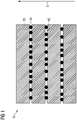
- the stack of magnetic laminations 10 comprises, in a manner known per se, a plurality of magnetic laminations 20 which are essentially in the form of planar flat parts with flat sides parallel to one another.
- the magnetic sheets 20 are spaced from each other by means of ceramic particles 30 which are located between the magnetic sheets 20 and are in contact with them.
- the ceramic particles 30 each have an almost perfectly spherical shape and a diameter of 40 micrometers.
- the ceramic particles 30 have a very homogeneous size distribution among themselves, ie the diameters of the ceramic particles are approximately Gaussian with a mean value of 3 micrometers and a standard deviation of 1.5 micrometers.
- ceramic particles which have a diameter of more than 5 micrometers and less than one micrometer are additionally filtered out.
- the ceramic particles 30 thus function to a certain extent as spacers between two adjacent magnetic sheets 20 and hold them the magnetic sheets are spaced at an average distance of about 2.5 microns from each other, since the ceramic particles are easily pressed into the metal surfaces during stack compression.
- the ceramic particles can also have a monomodal size distribution.
- the ceramic particles 30 are formed from aluminum oxide. In other exemplary embodiments that are not specifically illustrated, the ceramic particles 30 are formed alternatively or additionally with or from zirconium oxide and/or magnesium oxide and/or yttrium oxide and/or boron nitride and/or yttrium aluminum garnet and/or silicon nitride and/or silicon dioxide.
- the magnetic sheets 20 are punched or manufactured in some other way, for example by means of screen printing and/or stencil printing and subsequent sintering.
- the ceramic particles 30 can then be introduced between the magnetic sheets 20 as follows: A suspension with the ceramic particles 30 is used for this purpose.
- a suspension with the ceramic particles 30 is used for this purpose.
- an aqueous suspension with the ceramic particles 30 is used.
- the ceramic particles 30 can be introduced by means of a suspension of the ceramic particles 30 in an organic solvent.
- Optional binders and dispersants are added to the suspension.
- the suspension with the ceramic particles 30 is applied to the magnetic sheets 20 by means of spraying or dipping or printing, after which the suspension is dried and cured as a subsequent process step.
- the hardening step can also be omitted.
- the magnetic sheets 20 are then stacked on top of one another and pressed together in the direction perpendicular to the flat sides of the magnetic sheets 20, i.e. in the stacking direction S.
- the individual ceramic particles 30 are mechanically pressed into the flat sides of the magnetic sheets 20 .
- the ceramic particles 30 also remain fixed to the flat sides of the magnetic sheets 20 via the binder acting as an adhesive. In this way, the ceramic particles 30 remain positively and non-positively fixed between the magnetic sheets 20 even under high operating loads.
- the magnetic sheets 20 can also be pressed in other ways in further exemplary embodiments that are not shown specifically.
- the electric machine 200 comprises a stator 210 and a rotor 220. Both the stator 210 and the rotor 220 of the electric machine are each formed with a stack of magnetic sheets 10 according to the invention produced according to the invention as described above.
Landscapes
- Engineering & Computer Science (AREA)
- Power Engineering (AREA)
- Manufacturing & Machinery (AREA)
- Microelectronics & Electronic Packaging (AREA)
- Laminated Bodies (AREA)
- Hard Magnetic Materials (AREA)
- Manufacturing Cores, Coils, And Magnets (AREA)
- Sheets, Magazines, And Separation Thereof (AREA)
Claims (10)
- Empilement de tôles magnétiques d'une machine électrique comprenant une pluralité de tôles (20) magnétiques, qui sont isolées électriquement les unes des autres par le fait qu'elles sont à distance les unes des autres principalement dans une mesure de dégagement ne disparaissant pas, dans lequel les tôles (20) magnétiques sont à distance les unes des autres au moyen de plusieurs entretoises (30) intermédiaires, dans lequel les entretoises (30) sont constituées de particules de céramique, de sorte que les tôles (20) magnétiques de l'empilement de tôles magnétiques sont sur la partie prépondérante de leurs étendues en surface, isolées électriquement les unes des autres par respectivement une couche de gaz intermédiaire, caractérisé en ce que, entre respectivement deux tôles magnétiques de l'empilement de tôles magnétiques, un intervalle défini est réalisé au moyen de l'entretoise, grâce à quoi l'empilement de tôles magnétiques peut être refroidi par un fluide de refroidissement.
- Empilement de tôles magnétiques suivant la revendication 1, dans lequel l'intervalle est un entrefer, grâce à quoi l'empilement de tôles magnétiques peut être refroidi, de préférence, au moyen d'air de refroidissement.
- Empilement de tôles magnétiques suivant la revendication 1 ou 2, dans lequel les particules de céramique entre les tôles (20) magnétiques sont maintenues à coopération de force par compression ou par mise en paquet des tôles magnétiques.
- Empilement de tôles magnétiques suivant l'une des revendications précédentes, dans lequel les entretoises (30) sont en oxyde d'aluminium et/ou en oxyde de zirconium et/ou en oxyde de magnésium et/ou en oxyde d'yttrium et/ou en nitrure de bore et/ou en grenat d'yttrium et d'aluminium et/ou en nitrure de silicium et/ou en dioxyde de silicium ou en sont formées.
- Empilement de tôles magnétiques suivant l'une des revendications précédentes, dans lequel les particules ont un diamètre de 300 microns au plus, notamment de 100 microns au plus et, de préférence, un diamètre de 50 microns au plus.
- Empilement de tôles magnétiques suivant la revendication 5, dans lequel les diamètres des particules ont une répartition des dimensions, qui est monomodale ou au moins approximativement gaussienne, en ayant une valeur moyenne d'au moins 0,5 micron et/ou d'au plus 20 microns, en ayant, de préférence, une valeur moyenne d'au moins un micron et d'au plus 6 microns, d'une manière particulièrement préférée, en ayant une valeur moyenne d'au moins 2 microns et d'au plus 4 microns.
- Empilement de tôles magnétiques suivant l'une des revendications précédentes, dans lequel les particules sont sensiblement sphériques.
- Procédé de fabrication d'un empilement de tôles magnétiques suivant l'une des revendications précédentes, dans lequel on se procure des tôles (20) magnétiques, on se procure une suspension ayant les particules de céramique et on dépose la suspension sur une ou plusieurs tôles (20) magnétiques, on empile ensuite les tôles (20) magnétiques et pendant ou après qu'elles sont empilées, on les comprime ou on les met en paquet les unes avec les autres.
- Procédé suivant la revendication précédente, dans lequel on dépose, en pulvérisant et/ou en imprimant, la suspension et/ou en immergeant la ou les tôles (20) magnétiques dans la suspension.
- Machine électrique comprenant un empilement (10) de tôles magnétiques suivant l'une des revendications 1 à 7 et/ou fabriqué par un procédé suivant l'une des revendications 8 à 9.
Applications Claiming Priority (2)
| Application Number | Priority Date | Filing Date | Title |
|---|---|---|---|
| EP19172809.6A EP3736942A1 (fr) | 2019-05-06 | 2019-05-06 | Empilement de tôles magnétiques, procédé de fabrication d'un empilement de tôles magnétiques et machine électrique |
| PCT/EP2020/060661 WO2020224927A1 (fr) | 2019-05-06 | 2020-04-16 | Empilement de tôles magnétiques, procédé de production d'un empilement de tôles magnétiques et machine électrique |
Publications (2)
| Publication Number | Publication Date |
|---|---|
| EP3921919A1 EP3921919A1 (fr) | 2021-12-15 |
| EP3921919B1 true EP3921919B1 (fr) | 2022-12-28 |
Family
ID=66429292
Family Applications (2)
| Application Number | Title | Priority Date | Filing Date |
|---|---|---|---|
| EP19172809.6A Withdrawn EP3736942A1 (fr) | 2019-05-06 | 2019-05-06 | Empilement de tôles magnétiques, procédé de fabrication d'un empilement de tôles magnétiques et machine électrique |
| EP20721461.0A Active EP3921919B1 (fr) | 2019-05-06 | 2020-04-16 | Empilement de tôles magnétiques, procédé de fabrication d'un empilement de tôles magnétiques et machine électrique |
Family Applications Before (1)
| Application Number | Title | Priority Date | Filing Date |
|---|---|---|---|
| EP19172809.6A Withdrawn EP3736942A1 (fr) | 2019-05-06 | 2019-05-06 | Empilement de tôles magnétiques, procédé de fabrication d'un empilement de tôles magnétiques et machine électrique |
Country Status (5)
| Country | Link |
|---|---|
| US (1) | US12266464B2 (fr) |
| EP (2) | EP3736942A1 (fr) |
| CN (1) | CN113796001B (fr) |
| ES (1) | ES2941318T3 (fr) |
| WO (1) | WO2020224927A1 (fr) |
Families Citing this family (2)
| Publication number | Priority date | Publication date | Assignee | Title |
|---|---|---|---|---|
| CN114300214B (zh) * | 2021-12-31 | 2022-09-20 | 湖南稀土新能源材料有限责任公司 | 磁体组件及其制备方法、永磁电机 |
| DE102024112039A1 (de) * | 2024-04-29 | 2025-10-30 | Valeo Eautomotive Germany Gmbh | Lamellenblech für eine elektrische Maschine mit verbesserter Isolierung und Verfahren zu seiner Herstellung |
Family Cites Families (8)
| Publication number | Priority date | Publication date | Assignee | Title |
|---|---|---|---|---|
| WO2007146422A2 (fr) * | 2006-06-15 | 2007-12-21 | Board Of Regents, The University Of Texas System | Noyaux laminÉs de machinerie Électrique avec feuilletageS d'isolement |
| WO2011101985A1 (fr) * | 2010-02-22 | 2011-08-25 | トヨタ自動車株式会社 | Stator et procédé de fabrication de stator |
| JP5383781B2 (ja) * | 2011-12-16 | 2014-01-08 | 三菱電機株式会社 | 固定子鉄心、その製造方法、およびその固定子鉄心を用いた回転電機 |
| EP3255758A1 (fr) * | 2016-06-07 | 2017-12-13 | Siemens Aktiengesellschaft | Rotor pour une machine a reluctance |
| KR20180029541A (ko) * | 2016-09-12 | 2018-03-21 | 엘지이노텍 주식회사 | 자성시트 및 이를 포함하는 무선 전력 수신 장치 |
| US10601286B2 (en) * | 2017-06-13 | 2020-03-24 | Fukuta Electric & Machinery Co., Ltd. | Manufacturing method for a motor core |
| JPWO2019008722A1 (ja) * | 2017-07-06 | 2019-11-07 | 三菱電機株式会社 | 固定子、電動機、駆動装置、圧縮機、空気調和装置および固定子の製造方法 |
| CN107578879B (zh) * | 2017-08-14 | 2020-03-31 | 天津三环乐喜新材料有限公司 | 一种磁体组件及其制备方法 |
-
2019
- 2019-05-06 EP EP19172809.6A patent/EP3736942A1/fr not_active Withdrawn
-
2020
- 2020-04-16 EP EP20721461.0A patent/EP3921919B1/fr active Active
- 2020-04-16 WO PCT/EP2020/060661 patent/WO2020224927A1/fr not_active Ceased
- 2020-04-16 CN CN202080033654.8A patent/CN113796001B/zh active Active
- 2020-04-16 ES ES20721461T patent/ES2941318T3/es active Active
- 2020-04-16 US US17/608,562 patent/US12266464B2/en active Active
Also Published As
| Publication number | Publication date |
|---|---|
| ES2941318T3 (es) | 2023-05-19 |
| WO2020224927A1 (fr) | 2020-11-12 |
| CN113796001A (zh) | 2021-12-14 |
| US12266464B2 (en) | 2025-04-01 |
| US20220230799A1 (en) | 2022-07-21 |
| EP3921919A1 (fr) | 2021-12-15 |
| EP3736942A1 (fr) | 2020-11-11 |
| CN113796001B (zh) | 2024-07-19 |
Similar Documents
| Publication | Publication Date | Title |
|---|---|---|
| EP2769391B1 (fr) | Dispositif de transmission d'énergie électrique par induction | |
| DE102019123744A1 (de) | Elektrische maschine mit lokal abgestimmten eigenschaften | |
| EP3921919B1 (fr) | Empilement de tôles magnétiques, procédé de fabrication d'un empilement de tôles magnétiques et machine électrique | |
| DE102016119650A1 (de) | Verfahren zur Herstellung eines weichmagnetischen Kernmaterials | |
| DE112020003943T9 (de) | Herstellung von synchron-reluktanzmaschinen unter verwendung von additiver fertigung | |
| DE102019123745A1 (de) | Elektrische maschine mit lokal abgeglichenen eigenschaften | |
| DE102018215864A1 (de) | Rotor eines Elektromotors sowie Elektromotor | |
| DE102016119654A1 (de) | Verfahren zur Herstellung eines weichmagnetischen Kernmaterials | |
| WO2021185398A1 (fr) | Procédé destiné à produire un ensemble de couches à partir de métal en feuilles électriques, ensemble de couches ainsi produit, rotor ou stator et moteur électrique | |
| DE102014215318A1 (de) | Anisotrop weichmagnetisches Komposit-Material mit hoher Anisotropie der Permeabilität zur Unterdrückung von Querfluss und dessen Herstellung | |
| DE102013225875A1 (de) | Führung eines magnetischen Flusses | |
| DE102021130152A1 (de) | Rotor für eine Axialfluss-permanenterregte Synchronmaschine und Axialfluss-permanenterregte Synchronmaschine | |
| DE102020101642A1 (de) | Rotor, Verfahren zur Herstellung eines Rotors und Axialflussmaschine | |
| DE202011051649U1 (de) | Vorrichtung zur induktiven Übertragung elektrischer Energie | |
| EP3719958A1 (fr) | Matériau composite magnétique doux pour machines électriques | |
| EP3960334A1 (fr) | Procédé de fabrication d'une machine électrique ainsi qu'installation et véhicule | |
| DE102020124712A1 (de) | Elektrische induktorvorrichtung | |
| EP2626988B1 (fr) | Procédé de fabrication d'un rotor et rotor | |
| DE102007022093A1 (de) | Piezoelektrisches Vielschichtbauelement | |
| EP3959752B1 (fr) | Actionneur électromécanique à isolation céramique et son procédé de fabrication | |
| DE102009055103A1 (de) | Linearantrieb mit verbesserter Wirbelstromunterdrückung | |
| DE102009028259A1 (de) | Verfahren zur Herstellung von piezoelektrischen Werkstücken | |
| EP3618232A1 (fr) | Machine électrique, procédé de fabrication d'une machine électrique et véhicule électrique | |
| DE3414113C2 (fr) | ||
| DE102023212777A1 (de) | Verfahren zur Herstellung eines Magnetblechstapels für eine elektrische Maschine und elektrische Maschine |
Legal Events
| Date | Code | Title | Description |
|---|---|---|---|
| STAA | Information on the status of an ep patent application or granted ep patent |
Free format text: STATUS: UNKNOWN |
|
| STAA | Information on the status of an ep patent application or granted ep patent |
Free format text: STATUS: THE INTERNATIONAL PUBLICATION HAS BEEN MADE |
|
| PUAI | Public reference made under article 153(3) epc to a published international application that has entered the european phase |
Free format text: ORIGINAL CODE: 0009012 |
|
| STAA | Information on the status of an ep patent application or granted ep patent |
Free format text: STATUS: REQUEST FOR EXAMINATION WAS MADE |
|
| 17P | Request for examination filed |
Effective date: 20210910 |
|
| AK | Designated contracting states |
Kind code of ref document: A1 Designated state(s): AL AT BE BG CH CY CZ DE DK EE ES FI FR GB GR HR HU IE IS IT LI LT LU LV MC MK MT NL NO PL PT RO RS SE SI SK SM TR |
|
| DAV | Request for validation of the european patent (deleted) | ||
| DAX | Request for extension of the european patent (deleted) | ||
| GRAP | Despatch of communication of intention to grant a patent |
Free format text: ORIGINAL CODE: EPIDOSNIGR1 |
|
| STAA | Information on the status of an ep patent application or granted ep patent |
Free format text: STATUS: GRANT OF PATENT IS INTENDED |
|
| INTG | Intention to grant announced |
Effective date: 20220913 |
|
| GRAS | Grant fee paid |
Free format text: ORIGINAL CODE: EPIDOSNIGR3 |
|
| GRAA | (expected) grant |
Free format text: ORIGINAL CODE: 0009210 |
|
| STAA | Information on the status of an ep patent application or granted ep patent |
Free format text: STATUS: THE PATENT HAS BEEN GRANTED |
|
| AK | Designated contracting states |
Kind code of ref document: B1 Designated state(s): AL AT BE BG CH CY CZ DE DK EE ES FI FR GB GR HR HU IE IS IT LI LT LU LV MC MK MT NL NO PL PT RO RS SE SI SK SM TR |
|
| REG | Reference to a national code |
Ref country code: GB Ref legal event code: FG4D Free format text: NOT ENGLISH |
|
| REG | Reference to a national code |
Ref country code: CH Ref legal event code: EP |
|
| REG | Reference to a national code |
Ref country code: DE Ref legal event code: R096 Ref document number: 502020002285 Country of ref document: DE |
|
| REG | Reference to a national code |
Ref country code: AT Ref legal event code: REF Ref document number: 1541077 Country of ref document: AT Kind code of ref document: T Effective date: 20230115 |
|
| REG | Reference to a national code |
Ref country code: IE Ref legal event code: FG4D Free format text: LANGUAGE OF EP DOCUMENT: GERMAN |
|
| REG | Reference to a national code |
Ref country code: LT Ref legal event code: MG9D |
|
| PG25 | Lapsed in a contracting state [announced via postgrant information from national office to epo] |
Ref country code: SE Free format text: LAPSE BECAUSE OF FAILURE TO SUBMIT A TRANSLATION OF THE DESCRIPTION OR TO PAY THE FEE WITHIN THE PRESCRIBED TIME-LIMIT Effective date: 20221228 Ref country code: NO Free format text: LAPSE BECAUSE OF FAILURE TO SUBMIT A TRANSLATION OF THE DESCRIPTION OR TO PAY THE FEE WITHIN THE PRESCRIBED TIME-LIMIT Effective date: 20230328 Ref country code: LT Free format text: LAPSE BECAUSE OF FAILURE TO SUBMIT A TRANSLATION OF THE DESCRIPTION OR TO PAY THE FEE WITHIN THE PRESCRIBED TIME-LIMIT Effective date: 20221228 Ref country code: FI Free format text: LAPSE BECAUSE OF FAILURE TO SUBMIT A TRANSLATION OF THE DESCRIPTION OR TO PAY THE FEE WITHIN THE PRESCRIBED TIME-LIMIT Effective date: 20221228 |
|
| REG | Reference to a national code |
Ref country code: NL Ref legal event code: MP Effective date: 20221228 |
|
| REG | Reference to a national code |
Ref country code: ES Ref legal event code: FG2A Ref document number: 2941318 Country of ref document: ES Kind code of ref document: T3 Effective date: 20230519 |
|
| PG25 | Lapsed in a contracting state [announced via postgrant information from national office to epo] |
Ref country code: RS Free format text: LAPSE BECAUSE OF FAILURE TO SUBMIT A TRANSLATION OF THE DESCRIPTION OR TO PAY THE FEE WITHIN THE PRESCRIBED TIME-LIMIT Effective date: 20221228 Ref country code: LV Free format text: LAPSE BECAUSE OF FAILURE TO SUBMIT A TRANSLATION OF THE DESCRIPTION OR TO PAY THE FEE WITHIN THE PRESCRIBED TIME-LIMIT Effective date: 20221228 Ref country code: HR Free format text: LAPSE BECAUSE OF FAILURE TO SUBMIT A TRANSLATION OF THE DESCRIPTION OR TO PAY THE FEE WITHIN THE PRESCRIBED TIME-LIMIT Effective date: 20221228 Ref country code: GR Free format text: LAPSE BECAUSE OF FAILURE TO SUBMIT A TRANSLATION OF THE DESCRIPTION OR TO PAY THE FEE WITHIN THE PRESCRIBED TIME-LIMIT Effective date: 20230329 |
|
| PG25 | Lapsed in a contracting state [announced via postgrant information from national office to epo] |
Ref country code: NL Free format text: LAPSE BECAUSE OF FAILURE TO SUBMIT A TRANSLATION OF THE DESCRIPTION OR TO PAY THE FEE WITHIN THE PRESCRIBED TIME-LIMIT Effective date: 20221228 |
|
| PG25 | Lapsed in a contracting state [announced via postgrant information from national office to epo] |
Ref country code: SM Free format text: LAPSE BECAUSE OF FAILURE TO SUBMIT A TRANSLATION OF THE DESCRIPTION OR TO PAY THE FEE WITHIN THE PRESCRIBED TIME-LIMIT Effective date: 20221228 Ref country code: RO Free format text: LAPSE BECAUSE OF FAILURE TO SUBMIT A TRANSLATION OF THE DESCRIPTION OR TO PAY THE FEE WITHIN THE PRESCRIBED TIME-LIMIT Effective date: 20221228 Ref country code: PT Free format text: LAPSE BECAUSE OF FAILURE TO SUBMIT A TRANSLATION OF THE DESCRIPTION OR TO PAY THE FEE WITHIN THE PRESCRIBED TIME-LIMIT Effective date: 20230428 Ref country code: EE Free format text: LAPSE BECAUSE OF FAILURE TO SUBMIT A TRANSLATION OF THE DESCRIPTION OR TO PAY THE FEE WITHIN THE PRESCRIBED TIME-LIMIT Effective date: 20221228 Ref country code: CZ Free format text: LAPSE BECAUSE OF FAILURE TO SUBMIT A TRANSLATION OF THE DESCRIPTION OR TO PAY THE FEE WITHIN THE PRESCRIBED TIME-LIMIT Effective date: 20221228 |
|
| PG25 | Lapsed in a contracting state [announced via postgrant information from national office to epo] |
Ref country code: SK Free format text: LAPSE BECAUSE OF FAILURE TO SUBMIT A TRANSLATION OF THE DESCRIPTION OR TO PAY THE FEE WITHIN THE PRESCRIBED TIME-LIMIT Effective date: 20221228 Ref country code: PL Free format text: LAPSE BECAUSE OF FAILURE TO SUBMIT A TRANSLATION OF THE DESCRIPTION OR TO PAY THE FEE WITHIN THE PRESCRIBED TIME-LIMIT Effective date: 20221228 Ref country code: IS Free format text: LAPSE BECAUSE OF FAILURE TO SUBMIT A TRANSLATION OF THE DESCRIPTION OR TO PAY THE FEE WITHIN THE PRESCRIBED TIME-LIMIT Effective date: 20230428 Ref country code: AL Free format text: LAPSE BECAUSE OF FAILURE TO SUBMIT A TRANSLATION OF THE DESCRIPTION OR TO PAY THE FEE WITHIN THE PRESCRIBED TIME-LIMIT Effective date: 20221228 |
|
| REG | Reference to a national code |
Ref country code: DE Ref legal event code: R097 Ref document number: 502020002285 Country of ref document: DE |
|
| PG25 | Lapsed in a contracting state [announced via postgrant information from national office to epo] |
Ref country code: DK Free format text: LAPSE BECAUSE OF FAILURE TO SUBMIT A TRANSLATION OF THE DESCRIPTION OR TO PAY THE FEE WITHIN THE PRESCRIBED TIME-LIMIT Effective date: 20221228 |
|
| PLBE | No opposition filed within time limit |
Free format text: ORIGINAL CODE: 0009261 |
|
| STAA | Information on the status of an ep patent application or granted ep patent |
Free format text: STATUS: NO OPPOSITION FILED WITHIN TIME LIMIT |
|
| 26N | No opposition filed |
Effective date: 20230929 |
|
| PG25 | Lapsed in a contracting state [announced via postgrant information from national office to epo] |
Ref country code: LU Free format text: LAPSE BECAUSE OF NON-PAYMENT OF DUE FEES Effective date: 20230416 |
|
| PG25 | Lapsed in a contracting state [announced via postgrant information from national office to epo] |
Ref country code: MC Free format text: LAPSE BECAUSE OF FAILURE TO SUBMIT A TRANSLATION OF THE DESCRIPTION OR TO PAY THE FEE WITHIN THE PRESCRIBED TIME-LIMIT Effective date: 20221228 |
|
| PG25 | Lapsed in a contracting state [announced via postgrant information from national office to epo] |
Ref country code: SI Free format text: LAPSE BECAUSE OF FAILURE TO SUBMIT A TRANSLATION OF THE DESCRIPTION OR TO PAY THE FEE WITHIN THE PRESCRIBED TIME-LIMIT Effective date: 20221228 Ref country code: MC Free format text: LAPSE BECAUSE OF FAILURE TO SUBMIT A TRANSLATION OF THE DESCRIPTION OR TO PAY THE FEE WITHIN THE PRESCRIBED TIME-LIMIT Effective date: 20221228 |
|
| REG | Reference to a national code |
Ref country code: IE Ref legal event code: MM4A |
|
| PG25 | Lapsed in a contracting state [announced via postgrant information from national office to epo] |
Ref country code: IE Free format text: LAPSE BECAUSE OF NON-PAYMENT OF DUE FEES Effective date: 20230416 |
|
| PG25 | Lapsed in a contracting state [announced via postgrant information from national office to epo] |
Ref country code: IE Free format text: LAPSE BECAUSE OF NON-PAYMENT OF DUE FEES Effective date: 20230416 |
|
| PGFP | Annual fee paid to national office [announced via postgrant information from national office to epo] |
Ref country code: CH Payment date: 20240703 Year of fee payment: 5 Ref country code: ES Payment date: 20240722 Year of fee payment: 5 |
|
| PG25 | Lapsed in a contracting state [announced via postgrant information from national office to epo] |
Ref country code: BG Free format text: LAPSE BECAUSE OF FAILURE TO SUBMIT A TRANSLATION OF THE DESCRIPTION OR TO PAY THE FEE WITHIN THE PRESCRIBED TIME-LIMIT Effective date: 20221228 |
|
| PG25 | Lapsed in a contracting state [announced via postgrant information from national office to epo] |
Ref country code: BG Free format text: LAPSE BECAUSE OF FAILURE TO SUBMIT A TRANSLATION OF THE DESCRIPTION OR TO PAY THE FEE WITHIN THE PRESCRIBED TIME-LIMIT Effective date: 20221228 |
|
| PGFP | Annual fee paid to national office [announced via postgrant information from national office to epo] |
Ref country code: DE Payment date: 20250620 Year of fee payment: 6 |
|
| PGFP | Annual fee paid to national office [announced via postgrant information from national office to epo] |
Ref country code: GB Payment date: 20250507 Year of fee payment: 6 |
|
| PGFP | Annual fee paid to national office [announced via postgrant information from national office to epo] |
Ref country code: BE Payment date: 20250418 Year of fee payment: 6 Ref country code: IT Payment date: 20250417 Year of fee payment: 6 |
|
| PGFP | Annual fee paid to national office [announced via postgrant information from national office to epo] |
Ref country code: FR Payment date: 20250411 Year of fee payment: 6 |
|
| PGFP | Annual fee paid to national office [announced via postgrant information from national office to epo] |
Ref country code: AT Payment date: 20250721 Year of fee payment: 5 |
|
| PG25 | Lapsed in a contracting state [announced via postgrant information from national office to epo] |
Ref country code: CY Free format text: LAPSE BECAUSE OF FAILURE TO SUBMIT A TRANSLATION OF THE DESCRIPTION OR TO PAY THE FEE WITHIN THE PRESCRIBED TIME-LIMIT; INVALID AB INITIO Effective date: 20200416 |
|
| PG25 | Lapsed in a contracting state [announced via postgrant information from national office to epo] |
Ref country code: HU Free format text: LAPSE BECAUSE OF FAILURE TO SUBMIT A TRANSLATION OF THE DESCRIPTION OR TO PAY THE FEE WITHIN THE PRESCRIBED TIME-LIMIT; INVALID AB INITIO Effective date: 20200416 |
|
| REG | Reference to a national code |
Ref country code: CH Ref legal event code: H13 Free format text: ST27 STATUS EVENT CODE: U-0-0-H10-H13 (AS PROVIDED BY THE NATIONAL OFFICE) Effective date: 20251125 |
|
| PG25 | Lapsed in a contracting state [announced via postgrant information from national office to epo] |
Ref country code: TR Free format text: LAPSE BECAUSE OF FAILURE TO SUBMIT A TRANSLATION OF THE DESCRIPTION OR TO PAY THE FEE WITHIN THE PRESCRIBED TIME-LIMIT Effective date: 20221228 |
|
| PG25 | Lapsed in a contracting state [announced via postgrant information from national office to epo] |
Ref country code: CH Free format text: LAPSE BECAUSE OF NON-PAYMENT OF DUE FEES Effective date: 20250430 |