EP3960334A1 - Procédé de fabrication d'une machine électrique ainsi qu'installation et véhicule - Google Patents
Procédé de fabrication d'une machine électrique ainsi qu'installation et véhicule Download PDFInfo
- Publication number
- EP3960334A1 EP3960334A1 EP20193708.3A EP20193708A EP3960334A1 EP 3960334 A1 EP3960334 A1 EP 3960334A1 EP 20193708 A EP20193708 A EP 20193708A EP 3960334 A1 EP3960334 A1 EP 3960334A1
- Authority
- EP
- European Patent Office
- Prior art keywords
- stack
- green
- printed
- green part
- separating layer
- Prior art date
- Legal status (The legal status is an assumption and is not a legal conclusion. Google has not performed a legal analysis and makes no representation as to the accuracy of the status listed.)
- Pending
Links
- 0 *C1C(CC2)C2CC1 Chemical compound *C1C(CC2)C2CC1 0.000 description 2
Images

Classifications
-
- B—PERFORMING OPERATIONS; TRANSPORTING
- B22—CASTING; POWDER METALLURGY
- B22F—WORKING METALLIC POWDER; MANUFACTURE OF ARTICLES FROM METALLIC POWDER; MAKING METALLIC POWDER; APPARATUS OR DEVICES SPECIALLY ADAPTED FOR METALLIC POWDER
- B22F7/00—Manufacture of composite layers, workpieces, or articles, comprising metallic powder, by sintering the powder, with or without compacting wherein at least one part is obtained by sintering or compression
- B22F7/06—Manufacture of composite layers, workpieces, or articles, comprising metallic powder, by sintering the powder, with or without compacting wherein at least one part is obtained by sintering or compression of composite workpieces or articles from parts, e.g. to form tipped tools
-
- H—ELECTRICITY
- H02—GENERATION; CONVERSION OR DISTRIBUTION OF ELECTRIC POWER
- H02K—DYNAMO-ELECTRIC MACHINES
- H02K15/00—Processes or apparatus specially adapted for manufacturing, assembling, maintaining or repairing of dynamo-electric machines
- H02K15/02—Processes or apparatus specially adapted for manufacturing, assembling, maintaining or repairing of dynamo-electric machines of stator or rotor bodies
-
- H—ELECTRICITY
- H02—GENERATION; CONVERSION OR DISTRIBUTION OF ELECTRIC POWER
- H02K—DYNAMO-ELECTRIC MACHINES
- H02K15/00—Processes or apparatus specially adapted for manufacturing, assembling, maintaining or repairing of dynamo-electric machines
-
- B—PERFORMING OPERATIONS; TRANSPORTING
- B22—CASTING; POWDER METALLURGY
- B22F—WORKING METALLIC POWDER; MANUFACTURE OF ARTICLES FROM METALLIC POWDER; MAKING METALLIC POWDER; APPARATUS OR DEVICES SPECIALLY ADAPTED FOR METALLIC POWDER
- B22F10/00—Additive manufacturing of workpieces or articles from metallic powder
- B22F10/10—Formation of a green body
-
- B—PERFORMING OPERATIONS; TRANSPORTING
- B29—WORKING OF PLASTICS; WORKING OF SUBSTANCES IN A PLASTIC STATE IN GENERAL
- B29C—SHAPING OR JOINING OF PLASTICS; SHAPING OF MATERIAL IN A PLASTIC STATE, NOT OTHERWISE PROVIDED FOR; AFTER-TREATMENT OF THE SHAPED PRODUCTS, e.g. REPAIRING
- B29C64/00—Additive manufacturing, i.e. manufacturing of three-dimensional [3D] objects by additive deposition, additive agglomeration or additive layering, e.g. by 3D printing, stereolithography or selective laser sintering
- B29C64/10—Processes of additive manufacturing
- B29C64/106—Processes of additive manufacturing using only liquids or viscous materials, e.g. depositing a continuous bead of viscous material
-
- B—PERFORMING OPERATIONS; TRANSPORTING
- B29—WORKING OF PLASTICS; WORKING OF SUBSTANCES IN A PLASTIC STATE IN GENERAL
- B29C—SHAPING OR JOINING OF PLASTICS; SHAPING OF MATERIAL IN A PLASTIC STATE, NOT OTHERWISE PROVIDED FOR; AFTER-TREATMENT OF THE SHAPED PRODUCTS, e.g. REPAIRING
- B29C64/00—Additive manufacturing, i.e. manufacturing of three-dimensional [3D] objects by additive deposition, additive agglomeration or additive layering, e.g. by 3D printing, stereolithography or selective laser sintering
- B29C64/20—Apparatus for additive manufacturing; Details thereof or accessories therefor
- B29C64/205—Means for applying layers
-
- B—PERFORMING OPERATIONS; TRANSPORTING
- B33—ADDITIVE MANUFACTURING TECHNOLOGY
- B33Y—ADDITIVE MANUFACTURING, i.e. MANUFACTURING OF THREE-DIMENSIONAL [3D] OBJECTS BY ADDITIVE DEPOSITION, ADDITIVE AGGLOMERATION OR ADDITIVE LAYERING, e.g. BY 3D PRINTING, STEREOLITHOGRAPHY OR SELECTIVE LASER SINTERING
- B33Y10/00—Processes of additive manufacturing
-
- B—PERFORMING OPERATIONS; TRANSPORTING
- B33—ADDITIVE MANUFACTURING TECHNOLOGY
- B33Y—ADDITIVE MANUFACTURING, i.e. MANUFACTURING OF THREE-DIMENSIONAL [3D] OBJECTS BY ADDITIVE DEPOSITION, ADDITIVE AGGLOMERATION OR ADDITIVE LAYERING, e.g. BY 3D PRINTING, STEREOLITHOGRAPHY OR SELECTIVE LASER SINTERING
- B33Y80/00—Products made by additive manufacturing
-
- H—ELECTRICITY
- H02—GENERATION; CONVERSION OR DISTRIBUTION OF ELECTRIC POWER
- H02K—DYNAMO-ELECTRIC MACHINES
- H02K15/00—Processes or apparatus specially adapted for manufacturing, assembling, maintaining or repairing of dynamo-electric machines
- H02K15/02—Processes or apparatus specially adapted for manufacturing, assembling, maintaining or repairing of dynamo-electric machines of stator or rotor bodies
- H02K15/03—Processes or apparatus specially adapted for manufacturing, assembling, maintaining or repairing of dynamo-electric machines of stator or rotor bodies having permanent magnets
-
- B—PERFORMING OPERATIONS; TRANSPORTING
- B22—CASTING; POWDER METALLURGY
- B22F—WORKING METALLIC POWDER; MANUFACTURE OF ARTICLES FROM METALLIC POWDER; MAKING METALLIC POWDER; APPARATUS OR DEVICES SPECIALLY ADAPTED FOR METALLIC POWDER
- B22F2998/00—Supplementary information concerning processes or compositions relating to powder metallurgy
- B22F2998/10—Processes characterised by the sequence of their steps
-
- C—CHEMISTRY; METALLURGY
- C22—METALLURGY; FERROUS OR NON-FERROUS ALLOYS; TREATMENT OF ALLOYS OR NON-FERROUS METALS
- C22C—ALLOYS
- C22C2202/00—Physical properties
- C22C2202/02—Magnetic
-
- Y—GENERAL TAGGING OF NEW TECHNOLOGICAL DEVELOPMENTS; GENERAL TAGGING OF CROSS-SECTIONAL TECHNOLOGIES SPANNING OVER SEVERAL SECTIONS OF THE IPC; TECHNICAL SUBJECTS COVERED BY FORMER USPC CROSS-REFERENCE ART COLLECTIONS [XRACs] AND DIGESTS
- Y02—TECHNOLOGIES OR APPLICATIONS FOR MITIGATION OR ADAPTATION AGAINST CLIMATE CHANGE
- Y02P—CLIMATE CHANGE MITIGATION TECHNOLOGIES IN THE PRODUCTION OR PROCESSING OF GOODS
- Y02P10/00—Technologies related to metal processing
- Y02P10/25—Process efficiency
Definitions
- the invention relates to a method for manufacturing an electrical machine with a stack of magnetic sheets, as well as a system and a vehicle.
- the printing of magnetic sheets represents a new process for the production of magnetic sheets for electrical machines.
- a printing paste is first produced.
- This printing paste is then processed using a printing technique to form a green body (also known as a green part) in the form of a thick layer, and finally the green body produced in this way is converted into a metal sheet by thermal treatment, i.e. debinding and sintering.
- the individual magnetic sheets must then be provided with an insulating layer and laminated to form a stack of sheets.
- a stack of green parts is produced from magnetic sheets, with a first green part of the stack being printed, with a separating layer being applied to the first green part and in which the first green part with the Separating layer at least a second green part of a magnetic sheet is printed, with the green parts then being sintered together.
- the green parts in the method according to the invention are flat parts with two flat sides facing away from one another, with the phrase "a separating layer being applied to a green part” meaning that the separating layer is applied to or on a flat side of the green part, expediently on an im respective step of the process free flat side of the green part.
- first green part and/or the release layer can preferably be dried before the second green part is printed.
- the green parts can be sintered together, so that individual sintering of the green parts and subsequent assembly to form a stack of magnetic sheets can be dispensed with.
- the stack of green parts can first be partially or fully printed and the partially or fully printed stack of green parts can then be sintered. Consequently, the individual magnetic sheets can be sintered in parallel.
- a complex alignment of sintered individual magnetic sheets within the stack of magnetic sheets is not required according to the invention.
- the green parts are expediently treated with a first material, preferably a permanent-magnetic material or a material that forms permanent-magnetic material after sintering, and/or a second material, preferably a metallic and/or magnetizable material or a metallic material after sintering and/or magnetizable material.
- a first material preferably a permanent-magnetic material or a material that forms permanent-magnetic material after sintering
- a second material preferably a metallic and/or magnetizable material or a metallic material after sintering and/or magnetizable material.
- a separating layer is preferably applied again to the second green part of the stack and at least one further green part of the stack is printed on the second green part with the separating layer. It goes without saying that the second green part and/or the separating layer can preferably be dried before a further green part is printed.
- the method steps of the previously explained development of the invention become one or more Subjected to repetitions, with the other green part taking the place of the second green part.
- a separating layer is applied to the last printed green part of the stack and at least one other green part of the stack is printed with the separating layer on this last printed green part and so on.
- a stack with any number of green parts for example more than a thousand, can be printed.
- electrical machines with more than a thousand magnetic sheets can be manufactured easily and inexpensively.
- special requirements for electrical machines to be manufactured can also be easily met by means of the method according to the invention.
- the magnetic sheets of the stack expediently have an n-fold rotational symmetry and green parts that have already been printed are rotated by an angle of 360°/n or by a multiple of this angle before another green part of the stack is printed with an otherwise unchanged arrangement.
- the multiple of this angle is preferably not a factor of n. In this way, any deviations in process parameters from ideal process parameters can be compensated for.
- thickness gradients of individual green parts can be averaged out along one direction over the entire stack, so that differences in thickness of individual green parts along an entire stack do not add up, but instead compensate one another.
- any anisotropies that may occur during printing of the green parts can be averaged out along a travel direction of a print head by continuously changing the orientation of the green parts from green part to green part during printing.
- the precision of the stack of magnetic sheets can thus be increased and improved performance of the electrical machine manufactured according to the invention can be achieved.
- one, several or all of the green parts are preferably separated by means of a sieve and/or stencil printing.
- a sieve and/or stencil printing By means of screen and/or stencil printing, a high degree of precision can be achieved, in particular with regard to the shape of the respectively printed green parts, so that, according to the invention, precise production of the electrical machine and correspondingly high performance of the electrical machine are possible.
- the separating layer is advantageously formed with ceramic particles and/or the separating layer is applied with a green part coverage of at least 75 percent and/or the separating layer is coated with aluminum oxide and/or yttrium oxide and/or magnesium oxide and/or aluminum nitride and/or or boron nitride and/or YAG and/or mica materials.
- the green parts and consequently also the magnetic sheets resulting from the green parts can advantageously be kept at a distance with ceramic particles. The magnetic sheets can thus be easily isolated from one another as a result of the distance.
- the ceramic particles can expediently also serve as sintering inhibitors.
- Ceramic particles with a bimodal size distribution ie with a fine fraction and a coarse fraction, with the fine fraction suitably taking on the role of a sintering inhibitor and the coarse fraction preferably acting as a spacer.
- Ceramic particles with an average diameter of at most 5 micrometers are advantageously used.
- the ceramic particles preferably have a spherical shape.
- the ceramic particles have a whisker-like and/or platelet-like shape. In this way, the ceramic particles can easily absorb shear forces that occur during printing or sintering.
- the largest diameter of the whisker-shaped and/or platelet-shaped ceramic particles is expediently at most 10 micrometers, preferably at most 5 micrometers.
- the ceramic particles are preferably coated with aluminum oxide, Al 2 O 3 and/or yttrium oxide, Y 2 O 3 and/or magnesium oxide, MgO, and/or aluminum nitride and/or boron nitride and/or YAG and/or mica material or a mixture of said materials.
- the separating layer is expediently applied by means of a suspension, in particular sprayed on, the suspension preferably being dried before a further green part is printed.
- a separating layer in the form of a green film can be used.
- the stack of green parts is preferably debound and/or sintered to form a stack of magnetic sheets.
- resin is expediently introduced between the magnetic sheets of the stack of magnetic sheets, preferably in such a way that the resin electrically insulates the magnetic sheets from one another.
- the separating layer can be removed beforehand or the resin layer can be introduced between the magnetic sheets in addition to the separating layer.
- a rotor and/or a stator of the electrical machine is suitably formed with the stack of magnetic laminations.
- the system according to the invention and/or the vehicle according to the invention has/have an electric machine which is produced using a method according to the invention as explained above.
- the system according to the invention and/or the vehicle according to the invention has/have an electric machine in which the magnetic sheets of the stack can be arranged one on top of the other with particular precision. Consequently, the system according to the invention and the vehicle according to the invention can be designed to be particularly efficient.
- the inventive method shown is a method for manufacturing an electrical machine with a stack of magnetic sheets.
- the magnetic sheets are printed in a screen printing process by means of stencil printing.
- a printing paste 10 is first produced from metal powders, in the exemplary embodiment shown from pure iron powders.
- a first green body 20 is printed onto a substrate 30 by means of the printing paste 10 .
- the green body 20 is intended to form a magnetic sheet and has the shape of a thin layer on the substrate 30, so that the green body 20 has a lower flat side with which it rests on the substrate 30 and one that faces away from the lower flat side and has an upper flat side extending parallel to this.
- a printing screen (not shown explicitly in the drawing) with a template (not shown explicitly in the drawing) is used to print the green body 20 in order to define the shape of the green body 20 in two-dimensional directions of the substrate 30 .
- a nozzle 40 prints the printing paste 10 through the screen onto the substrate 30.
- the substrate 30 carries an orientation marking 50, by means of which the orientation of the substrate 30 and consequently also of the first green body 20 can be easily identified.
- First green body 20 and substrate 30 have a 6-fold rotational symmetry in the exemplary embodiment shown. In other exemplary embodiments that are not specifically illustrated, there can be a different rotational symmetry, for example a 50-fold rotational symmetry or some other rotational symmetry.
- the first green body 20 After the first green body 20 is printed, the first green body 20 can optionally be partially or completely dried.
- a suspension 70 is sprayed by means of a nozzle 60 onto the upper flat side of the first green body 20 as a separating layer, which suspension contains a volatile carrier liquid and ceramic particles 80 held in the carrier liquid.
- the ceramic particles 80 of the suspension 70 have a spherical shape and an average particle diameter of less than 5 micrometers and are formed with aluminum oxide, ie with Al 2 O 3 .
- the ceramic particles can also be particles of magnesium oxide and/or yttrium oxide and/or aluminum nitride and/or boron nitride in further exemplary embodiments.
- the ceramic particles can comprise YAG and/or mica particles.
- the size distribution of the ceramic particles is a bimodal size distribution, i.e. there are smaller ceramic particles 80 in the sense of a fine fraction of the ceramic particles, which act as sintering inhibitors between green bodies 20 and there are coarser ceramic particles 80, which can act as spacers between green bodies 20 and enable electrical insulation between the green bodies 20 made of magnetic sheets.
- the ceramic particles can have a whisker-like or platelet-like shape.
- a green film with ceramic particles can also be applied to the green body 20 in further exemplary embodiments that are not specifically shown.
- the ceramic particles 80 form a separating layer less than 10 micrometers thick, which covers more than 75 percent of the flat sides of the green part 20 .
- the ceramic particles 80 were applied by means of the suspension 70, which is first dried so that the carrier liquid in the suspension 70 can evaporate.
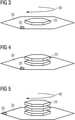
- the substrate 30 is shown with the green body 20 with the ceramic particles 80 (in FIGS Figures 3 to 7 not shown explicitly) by means of a rotation of 90 by 60 degrees, i.e. by 360°/n for an n-fold rotational symmetry.
- the rest of the arrangement, such as the nozzle 40 for the printing paste 10 and the nozzle 60 for the suspension 70 remains compared to the original arrangement Figures 1 and 2 unchanged.
- correct rotation can easily be monitored by rotating the orientation marking 50, which consequently also has to be rotated further by 60° in the exemplary embodiment shown.
- another green body 20 is placed on the separating layer formed with ceramic particles 80, as in FIG 4 shown printed, which has the same geometric shape as the green body 20 previously printed on the substrate 30.
- the green body 20 is printed in such a way that it exactly covers the green body 20 previously printed on the substrate 30 in a direction perpendicular to the planar extensions of the substrate 30 .
- a separating layer with ceramic particles 80 is again applied to this further green body 20 and dried. This is done as already based on the 2 explained.
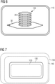
- the green bodies 20 printed on top of one another and separated from one another by separating layers with ceramic particles 80 form a stack 100 of green bodies 20.
- the stack 100 of green bodies 20 formed in this way is now debound together as a stack 100 and sintered in a sintering furnace 110. In this way, the green bodies 20 are sintered into a stack 100 of magnetic sheets.
- the ceramic particles 80 between the magnetic sheets can be removed in a further step.
- the stack 100 can be immersed in resin, so that in the stack 100 of magnetic laminations, the individual magnetic laminations are reliably electrically insulated from one another and the stack 100 is mechanically strengthened.
- the stack 100 is now provided with a shaft (not explicitly shown) in a manner known per se, so that it forms a rotor 120 .
- the rotor 120 is installed in a manner known per se together with a stator 130 to form a machine 140 manufactured according to the invention, which in the exemplary embodiment shown is an electric motor manufactured according to the invention.
- the machine 140 manufactured according to the invention can form an electrical generator.
- the plant 150 shown is an industrial plant that contains the electrical machine manufactured according to the invention 140 has.
- an autonomous storage vehicle can be present, which has the electrical machine 140 manufactured according to the invention.
Landscapes
- Engineering & Computer Science (AREA)
- Manufacturing & Machinery (AREA)
- Materials Engineering (AREA)
- Chemical & Material Sciences (AREA)
- Power Engineering (AREA)
- Mechanical Engineering (AREA)
- Physics & Mathematics (AREA)
- Optics & Photonics (AREA)
- Composite Materials (AREA)
- Soft Magnetic Materials (AREA)
- Manufacturing Cores, Coils, And Magnets (AREA)
- Producing Shaped Articles From Materials (AREA)
- Hard Magnetic Materials (AREA)
- Powder Metallurgy (AREA)
Priority Applications (3)
| Application Number | Priority Date | Filing Date | Title |
|---|---|---|---|
| EP20193708.3A EP3960334A1 (fr) | 2020-08-31 | 2020-08-31 | Procédé de fabrication d'une machine électrique ainsi qu'installation et véhicule |
| US17/460,486 US11888362B2 (en) | 2020-08-31 | 2021-08-30 | Method to manufacture an electric machine, installation, vehicle |
| CN202111013726.5A CN114123675B (zh) | 2020-08-31 | 2021-08-31 | 用于制造电机的方法以及设备和车辆 |
Applications Claiming Priority (1)
| Application Number | Priority Date | Filing Date | Title |
|---|---|---|---|
| EP20193708.3A EP3960334A1 (fr) | 2020-08-31 | 2020-08-31 | Procédé de fabrication d'une machine électrique ainsi qu'installation et véhicule |
Publications (1)
| Publication Number | Publication Date |
|---|---|
| EP3960334A1 true EP3960334A1 (fr) | 2022-03-02 |
Family
ID=72292434
Family Applications (1)
| Application Number | Title | Priority Date | Filing Date |
|---|---|---|---|
| EP20193708.3A Pending EP3960334A1 (fr) | 2020-08-31 | 2020-08-31 | Procédé de fabrication d'une machine électrique ainsi qu'installation et véhicule |
Country Status (3)
| Country | Link |
|---|---|
| US (1) | US11888362B2 (fr) |
| EP (1) | EP3960334A1 (fr) |
| CN (1) | CN114123675B (fr) |
Families Citing this family (2)
| Publication number | Priority date | Publication date | Assignee | Title |
|---|---|---|---|---|
| EP3960334A1 (fr) * | 2020-08-31 | 2022-03-02 | Siemens Aktiengesellschaft | Procédé de fabrication d'une machine électrique ainsi qu'installation et véhicule |
| EP4376264A1 (fr) * | 2022-11-24 | 2024-05-29 | Siemens Aktiengesellschaft | Procédé de fabrication d'un paquet de tôles et machine électrique |
Citations (5)
| Publication number | Priority date | Publication date | Assignee | Title |
|---|---|---|---|---|
| DE102012015127A1 (de) * | 2012-07-27 | 2014-02-13 | Fraunhofer-Gesellschaft zur Förderung der angewandten Forschung e.V. | Sinterunterlage |
| DE102014104596A1 (de) * | 2014-04-01 | 2015-10-01 | Bundesrepublik Deutschland, Vertreten Durch Den Bundesminister Für Wirtschaft Und Energie, Dieser Vertreten Durch Den Präsidenten Der Bundesanstalt Für Materialforschung Und -Prüfung (Bam) | Aufbau einer Diffusionsbarriere in einem schlickerbasierten additiven Fertigungsprozess zur Herstellung eines keramischen Grünkörpers |
| WO2020043565A1 (fr) * | 2018-08-31 | 2020-03-05 | Siemens Aktiengesellschaft | Procédé de production d'un produit fritté, dispositif de frittage et procédé de production d'une machine électrique |
| WO2020064299A1 (fr) * | 2018-09-27 | 2020-04-02 | Siemens Aktiengesellschaft | Procédé de frittage d'un produit à fritter à plusieurs composants, machine électrique et véhicule électrique |
| EP3653320A1 (fr) * | 2018-11-16 | 2020-05-20 | Siemens Aktiengesellschaft | Procédé de frittage d'un produit de frittage |
Family Cites Families (9)
| Publication number | Priority date | Publication date | Assignee | Title |
|---|---|---|---|---|
| DE2145553C3 (de) * | 1971-09-11 | 1979-07-19 | Loi Industrieofenanlagen Gmbh, 4300 Essen | Verfahren zur Herstellung von Blechpaketen für die feldführenden TeUe elektrischer Maschinen und Geräte |
| US6121709A (en) * | 1997-10-16 | 2000-09-19 | Alliedsignal Inc. | Rotor assembly having bonded lamination stack |
| US7224096B2 (en) * | 1997-10-16 | 2007-05-29 | Honeywell International Inc. | Rotatable assemblies having chemically bonded lamination stacks |
| GB0616116D0 (en) * | 2006-08-12 | 2006-09-20 | Rolls Royce Plc | A method of forming a component on a substrate |
| CN201478887U (zh) * | 2009-08-31 | 2010-05-19 | 吕元之 | 软磁复合材料电机磁芯 |
| DE102015216969A1 (de) * | 2015-09-04 | 2017-03-09 | Robert Bosch Gmbh | Beschichteter Sinterwerkstoff, Verfahren zu dessen Herstellung und Verwendungen des beschichteten Sinterwerkstoffs |
| DE102016203739A1 (de) * | 2016-03-08 | 2017-09-14 | Brose Fahrzeugteile GmbH & Co. Kommanditgesellschaft, Würzburg | Paketsystem einer elektrischen Maschine, elektrische Maschine und Verfahren zur Herstellung des Paketsystems |
| CN109961915A (zh) * | 2019-03-05 | 2019-07-02 | 宁波金科磁业有限公司 | 一种磁片成型方法 |
| EP3960334A1 (fr) * | 2020-08-31 | 2022-03-02 | Siemens Aktiengesellschaft | Procédé de fabrication d'une machine électrique ainsi qu'installation et véhicule |
-
2020
- 2020-08-31 EP EP20193708.3A patent/EP3960334A1/fr active Pending
-
2021
- 2021-08-30 US US17/460,486 patent/US11888362B2/en active Active
- 2021-08-31 CN CN202111013726.5A patent/CN114123675B/zh active Active
Patent Citations (5)
| Publication number | Priority date | Publication date | Assignee | Title |
|---|---|---|---|---|
| DE102012015127A1 (de) * | 2012-07-27 | 2014-02-13 | Fraunhofer-Gesellschaft zur Förderung der angewandten Forschung e.V. | Sinterunterlage |
| DE102014104596A1 (de) * | 2014-04-01 | 2015-10-01 | Bundesrepublik Deutschland, Vertreten Durch Den Bundesminister Für Wirtschaft Und Energie, Dieser Vertreten Durch Den Präsidenten Der Bundesanstalt Für Materialforschung Und -Prüfung (Bam) | Aufbau einer Diffusionsbarriere in einem schlickerbasierten additiven Fertigungsprozess zur Herstellung eines keramischen Grünkörpers |
| WO2020043565A1 (fr) * | 2018-08-31 | 2020-03-05 | Siemens Aktiengesellschaft | Procédé de production d'un produit fritté, dispositif de frittage et procédé de production d'une machine électrique |
| WO2020064299A1 (fr) * | 2018-09-27 | 2020-04-02 | Siemens Aktiengesellschaft | Procédé de frittage d'un produit à fritter à plusieurs composants, machine électrique et véhicule électrique |
| EP3653320A1 (fr) * | 2018-11-16 | 2020-05-20 | Siemens Aktiengesellschaft | Procédé de frittage d'un produit de frittage |
Also Published As
| Publication number | Publication date |
|---|---|
| US20220069680A1 (en) | 2022-03-03 |
| US11888362B2 (en) | 2024-01-30 |
| CN114123675A (zh) | 2022-03-01 |
| CN114123675B (zh) | 2024-07-23 |
Similar Documents
| Publication | Publication Date | Title |
|---|---|---|
| DE69301312T2 (de) | Verfahren zur Herstellung vielpoliger Magneten | |
| WO2004077583A1 (fr) | Composant electrique multicouche et empilement de couches | |
| EP3932591A1 (fr) | Tôle magnétique, procédé de fabrication d'une tôle magnétique, rotor et machine électrique | |
| DE102016119650A1 (de) | Verfahren zur Herstellung eines weichmagnetischen Kernmaterials | |
| DE102016119654B4 (de) | Verfahren zur Herstellung eines weichmagnetischen Kernmaterials und weichmagnetisches Kernmaterial | |
| EP3723249A1 (fr) | Procédé de fabrication d'une tôle magnétique et d'un empilement de tôles magnétiques ainsi que machine électrique et véhicule électrique | |
| DE102020130988A1 (de) | Verfahren zur Herstellung einer Schichtanordnung aus Elektroblech, danach hergestellte Schichtanordnung, Rotor oder Stator sowie Elektromotor | |
| EP3960334A1 (fr) | Procédé de fabrication d'une machine électrique ainsi qu'installation et véhicule | |
| DE102022119376A1 (de) | Elektroblech für eine elektrische Maschine sowie Verfahren zur Herstellung eines Elektroblechs | |
| EP3921919B1 (fr) | Empilement de tôles magnétiques, procédé de fabrication d'un empilement de tôles magnétiques et machine électrique | |
| WO2022112038A1 (fr) | Procédé pour produire une couche de matériau avec au moins un évidement | |
| EP3859953A1 (fr) | Empilement de tôles pour une machine électrique rotative | |
| EP3708938A1 (fr) | Fabrication d'une tôle magnétique | |
| DE102021133243A1 (de) | Blechpaketabschnitt mit Filigrangeflecht, Verfahren zum Herstellen eines Blechpaketabschnittes, Blechpaket, Aktivteil und elektrische Maschine | |
| EP4193449A1 (fr) | Machine électrique et installation | |
| EP3975383A1 (fr) | Machine électrique, procédé et installation | |
| WO2020099037A1 (fr) | Tôle magnétique à surface structurée pour raffinement de domaines | |
| DE102013209186B4 (de) | Komponente einer elektrischen Maschine sowie Verfahren zu deren Herstellung | |
| EP3979465A1 (fr) | Machine électrique et installation | |
| DE102023212777A1 (de) | Verfahren zur Herstellung eines Magnetblechstapels für eine elektrische Maschine und elektrische Maschine | |
| WO2019029920A1 (fr) | Procédé de métallisation d'une carte de circuit imprimé et carte de circuit imprimé correspondante | |
| WO2025180594A1 (fr) | Procédé de production d'un noyau magnétique doux, rotor d'une machine électrique et machine électrique | |
| WO2023104431A1 (fr) | Procédé de fabrication d'un noyau feuilleté d'une machine électrique | |
| DE102023212780A1 (de) | Verfahren zur Herstellung eines Magnetblechstapels für eine elektrische Maschine und elektrische Maschine | |
| WO2023104434A1 (fr) | Procédé de production d'un noyau stratifié d'une machine électrique |
Legal Events
| Date | Code | Title | Description |
|---|---|---|---|
| PUAI | Public reference made under article 153(3) epc to a published international application that has entered the european phase |
Free format text: ORIGINAL CODE: 0009012 |
|
| STAA | Information on the status of an ep patent application or granted ep patent |
Free format text: STATUS: THE APPLICATION HAS BEEN PUBLISHED |
|
| AK | Designated contracting states |
Kind code of ref document: A1 Designated state(s): AL AT BE BG CH CY CZ DE DK EE ES FI FR GB GR HR HU IE IS IT LI LT LU LV MC MK MT NL NO PL PT RO RS SE SI SK SM TR |
|
| STAA | Information on the status of an ep patent application or granted ep patent |
Free format text: STATUS: REQUEST FOR EXAMINATION WAS MADE |
|
| 17P | Request for examination filed |
Effective date: 20220831 |
|
| RBV | Designated contracting states (corrected) |
Designated state(s): AL AT BE BG CH CY CZ DE DK EE ES FI FR GB GR HR HU IE IS IT LI LT LU LV MC MK MT NL NO PL PT RO RS SE SI SK SM TR |