EP3922494A1 - Luftverteilungsschlauch für einen hvac-kreislauf eines fahrzeugs - Google Patents
Luftverteilungsschlauch für einen hvac-kreislauf eines fahrzeugs Download PDFInfo
- Publication number
- EP3922494A1 EP3922494A1 EP20305619.7A EP20305619A EP3922494A1 EP 3922494 A1 EP3922494 A1 EP 3922494A1 EP 20305619 A EP20305619 A EP 20305619A EP 3922494 A1 EP3922494 A1 EP 3922494A1
- Authority
- EP
- European Patent Office
- Prior art keywords
- pipe
- microperforations
- wall
- mold
- sheets
- Prior art date
- Legal status (The legal status is an assumption and is not a legal conclusion. Google has not performed a legal analysis and makes no representation as to the accuracy of the status listed.)
- Granted
Links
Images



Classifications
-
- B—PERFORMING OPERATIONS; TRANSPORTING
- B60—VEHICLES IN GENERAL
- B60H—ARRANGEMENTS OF HEATING, COOLING, VENTILATING OR OTHER AIR-TREATING DEVICES SPECIALLY ADAPTED FOR PASSENGER OR GOODS SPACES OF VEHICLES
- B60H1/00—Heating, cooling or ventilating devices
- B60H1/00507—Details, e.g. mounting arrangements, desaeration devices
- B60H1/00557—Details of ducts or cables
- B60H1/00564—Details of ducts or cables of air ducts
Definitions
- the present invention relates in particular to an air distribution pipe for a heating, ventilation and air conditioning circuit of a vehicle, for example a motor vehicle.
- This circuit is known under the name of HVAC circuit (acronym for heating, ventilation and air-conditioning) and more particularly of HVAC circuit (acronym for heating, ventilation and air-conditioning ) .
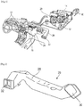
- FIG. 1 An HVAC or HVAC circuit is schematically represented on figure 1 .
- This type of circuit 10 generally comprises a compressor 12, a condenser 14, an expansion valve 16 and an evaporator 18.
- a refrigerant fluid (such as R1234yf) first passes through the compressor 12 in order to come out in the gaseous state at high pressure.
- the condenser 14 makes it possible to change this fluid from the gaseous state to the liquid state. It is during this step that the fluid gives up its thermal energy, before passing through the regulator 16.
- the regulator 16 makes it possible to drop the pressure of the fluid and consequently its temperature. It also makes it possible to regulate the flow of the fluid in the circuit 10.
- the evaporator 18 is placed under the dashboard of the vehicle and has two functions: to cool the air entering the passenger compartment and to dry this air. A fan 20 passes outside air through the evaporator 18. This air loses its heat and humidity, before being redistributed into the passenger compartment through a filter and ventilation grilles 22, creating a feeling of freshness.
- the evaporator 18 is located in a cooling and heating unit 24 which comprises a heating body in the event that the air should be on the contrary is heated to heat the passenger compartment of the vehicle.
- the air is brought from the unit 24 to the grids 22 by air distribution pipes 26, one of which is diagrammatically shown in figure 2 .
- a distribution pipe 26 can have a complex shape to bypass certain obstacles in its mounting environment. It has a generally elongated shape and comprises a tubular body 28 having an air inlet opening 30 at one end and at least one air outlet opening 32 at its opposite end.
- the pipe may have a non-circular shape in section.
- the pipe 32 can be made of a cellular material (or alveolar, commonly called foam material in English) and elastically deformable.
- cellular material is understood to mean a material which comprises cells or open and closed cavities of small size which make it possible to lighten and soften the material.
- the material is elastically deformable, that is to say it is flexible and can recover its original shape after being deformed.
- the applicant sought a solution for improving an air distribution pipe of an HVAC circuit, in order to attenuate the noise transmitted to the passenger compartment of the vehicle and coming in particular from the fan and the compressor. this circuit.
- the invention provides a simple, efficient and economical solution for attenuating the noise transmitted by an air distribution pipe of an HVAC circuit of a vehicle.
- the present invention relates to an air distribution pipe for an HVAC circuit of a vehicle, this pipe comprising a single monolayer tubular wall made from a cellular material and elastically deformable, characterized in that said wall comprises acoustic attenuation microperforations, these microperforations extending from at least one of the internal and external surfaces of the wall towards the other of these surfaces, or even to the other of these surfaces.
- the pipe comprises a single tubular and monolayer wall.
- the pipe is therefore simple to produce, unlike pipes of the prior art which may have several layers or superimposed walls.
- the wall of the pipe according to the invention is formed from the cellular and elastically deformable material mentioned in the above.
- the pipe has a single layer or wall is advantageous for widening the frequency range of sound attenuation, in particular towards the low frequencies.
- a multilayer pipe of the prior art in general has an acoustic attenuation property at medium and high frequencies (typically greater than 800 Hz).
- the pipe according to the invention can, on the contrary, have a wider acoustic attenuation property, including at low frequencies (typically up to 50 Hz).
- the pipe according to the invention can have any shape, in particular in section.
- the pipe is microperforated, the microperforations being produced from the inside and / or the exterior of the pipe and being through or not through.
- a first remark is that the microperforations therefore extend substantially radially (relative to the longitudinal or elongation axis of the pipe) over all or part of the extent or the thickness of the pipe, that is to say say over all or part of the thickness of its wall. This first point is important and goes against what a person skilled in the art would consider in order to improve the acoustic properties of the pipe. Indeed, the pipe having the function of distributing air, it would not occur to a person skilled in the art to pierce the single wall of this pipe at the risk of generating air leaks.
- the microperforations in the pipe are configured to limit or prevent these leaks. They therefore preferably have a very small size.
- the passage section of their radially internal ends is zero.
- their radially internal ends therefore located towards the inside of the pipe, have a passage section which may be zero (due to the elastic return of the material after making the microperforations) or not zero but which is sufficiently small to ensure sufficient sealing of the pipe in use.
- the microperforations can have passage sections which narrow radially towards the interior of the pipe. The microperforations then have in this case a tapered shape flared outwards.
- Microperforations may be visible to the naked eye on the outer surface of the pipe. Conversely, the size of the passage section of the radially internal ends of the microperforations may be such that it is not possible to observe with the naked eye whether or not the microperforations open into the interior of the pipe. In other words, even if a light source is disposed inside the pipe, it may not be possible to see this light with the naked eye through the microperforations due to the tight size of the microperforations at their ends. radially internal. As will be mentioned in what follows, the microperforations can be produced by mechanical punching or drilling, for example from outside the pipe.
- Mechanical punching is an operation during which one or more punches (in the form of a sharp point for example) are engaged in a material to pierce it. Due to the elastic properties of the material of the tube, the microperforations produced by punching tend to close after withdrawal of the punches, which allows the internal ends of the microperforations to have a reduced passage section.
- microperforations could be made by laser drilling or other suitable technique.
- the size of the microperforations can be measured in the free state without stress on the pipe. Naturally, due to the elastic properties of the material, pulling on the pipe deforms it and can cause this size to increase. However, in operation, the pipe is mounted snug in its surroundings and should not be strained. In other words, the size of the microperforations of the pipe must not vary before and after installation in a vehicle.
- a pipe according to the invention can have additional gains at low frequencies, typically between 50 and 800Hz.
- the improved acoustic attenuation of the pipe according to the invention is linked to the effect of sound absorption by the wall of the pipe. Indeed, the measured absorption values show a good correlation between wall absorption and acoustic attenuation.
- the low frequency absorption of a multi-perforated pipe increases mainly through a dissipative effect in the wall thickness. Transmission through the wall is also increased, but in a secondary way.
- the present invention also relates to an HVAC circuit of a vehicle, comprising at least one pipe as described above, for example just upstream of a ventilation grid.
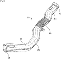
- the figures 3 and 4 illustrate an embodiment of an air distribution pipe 34 for an HVAC or HVAC circuit of a vehicle, for example an automobile.
- the pipe 34 has a generally elongated shape and comprises a single tubular and monolayer wall 36 which is made from a cellular and elastically deformable material such as a thermoplastic elastomer (PP, PE, etc.).
- a thermoplastic elastomer PP, PE, etc.
- the pipe has an average diameter of between 20 and 250mm approximately, preferably between 40 and 80mm, more preferably between 50 and 70mm.
- the pipe has for example a length between 100 and 1500mm, preferably between 200 and 800mm, and more preferably between 500 and 700mm.
- the pipe 34 includes an air passage opening at each of its longitudinal ends.
- the first opening 38 is for example an air inlet opening and the second opening 40 is for example an air outlet opening.
- the passage sections of the pipe 34 and of its openings 38, 40 are not necessarily circular, as in the example shown. Alternatively, the pipe could include two or more air outlet openings.
- the wall 36 of the pipe 34 is best seen at the figure 5 which is a sectional view of the pipe 34.
- the wall 36 has a thickness between 1 and 10mm, preferably between 2 and 8mm, and more preferably between 3 and 6mm.
- the cellular material has a density between 30 and 300kg / m 3, preferably between 40 and 200kg / m 3, more preferably between 50 and 130 kg / m 3 (measured according to EN ISO 845).
- the cellular material has an elongation at break of between 50 and 300%, preferably between 80 and 200%, and more preferably between 100 and 150% (measured according to standard EN ISO 1798).
- the cellular material has a tensile strength of between 0.2 and 2 MPa, preferably between 0.4 and 1 MPa, and more preferably between 0.5 and 0.8 MPa (measured according to standard EN ISO 1798).
- the wall 36 comprises hollow or empty cells 42, some of which are open and others are closed.
- the cells 42 located at a distance from the internal 36a and external 36b surfaces of the wall 36 are closed while those 42 located and opening out at the level of the surfaces 36a, 36b are open.
- the cells 42 have a size of between 1.1 and 3mm, preferably between 0.2 and 2mm, and more preferably between 0.3 and 1.1mm.
- the wall 36 further comprises microperforations 44 for acoustic attenuation.
- the wall 36 may include at least one portion 36c comprising microperforations 44 and at least one portion 36d, 36e devoid of microperforations.
- the wall 36 comprises a middle or intermediate portion 36c comprising microperforations 44, this portion being better visible at the figure 4 , and end portions 36d, 36e comprising the openings 38, 40 which are devoid of microperforations.
- the microperforations 44 extend over only part of the thickness of the wall 36, from its outer surface 36b.
- the microperforations 44 extend over the entire thickness of the wall 36, from its external surface 36b to its internal surface 36a. It is then said that the microperforations 44 are through.
- the microperforations 44 have a general conical or frustoconical shape with a flaring towards the outside (or on the contrary a narrowing towards the inside), as is schematically represented on the diagram. figure 7 .
- Each of the microperforations 44 extends along an axis of elongation X.
- the axes of elongation X of the microperforations 44 can be oriented randomly.
- the axes of the microperforations are oriented in the radial direction, that is to say each perpendicular to the surface 36b of the wall 36.
- they could have a certain degree of d. 'inclination with respect to a direction normal to the surface 36b of the wall 36.
- the microperforations 44 have radially internal ends which have a passage section S1 which may be less than that S2 of the radially external ends of the microperforations. In the event that the microperforations are non-through ( figure 5 ), S1 is zero. In the case where the microperforations are through, S1 can be zero or small and for example less than or equal to 1.5mm 2 , preferably less than or equal to 1mm 2 , and more preferably less than or equal to 0.5mm 2 , when the pipe is in the free state without stress.
- the passage sections S1, S2 of the microperforations 44 can be chosen as a function of the density of the material of the wall 36 and of the thickness of this wall.
- the wall comprises at least five microperforations per cm 2 .
- the radially outer ends of the microperforations 44 have for example a diameter of between 0.2 and 3mm, preferably between 0.3 and 2.5mm, and more preferably between 0.5 and 2mm, and even more preferably between 0.8 and 1.2mm.
- the microperforations 44 are preferably configured to give the pipe an acoustic attenuation of about 10dB at frequencies below 1000Hz, and for example between 50 and 800Hz;
- the present invention also relates to an HVAC or HVAC circuit of a vehicle, comprising at least one pipe 34 as described above, for example just upstream of a ventilation grille 22, as illustrated in FIG. figure 1 .
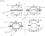
- the stages of figure 8a illustrate the manufacture of a part by blowing in a mold 50 by means of two sheets 52.
- the two sheets 52 form the raw material. They are superimposed and preferably of the same dimensions. They can be secured to one another along two opposite sides 54.
- the sheets 52 are arranged between the two parts of a mold 50, such as a mold and a counter-mold.
- the mold 50 is closed and the sheets 52 are heated inside the mold to soften their material, preferably TPE (step 1 top left at figure 8a ).
- Air is then blown inside the mold 50 (arrow F1), between the sheets 52, to force them to move away from each other and to press against the walls of the mold 50 (step 2 top right at the figure 8a ).
- the sheets 52 thus follow the imprint of the mold 50 and adopt their final or almost final shape (step 3 at the bottom left at figure 8a ).
- the tackle sheets 52 against the walls of the mold 50 can be facilitated by sucking in the air (arrows F2) and creating a partial vacuum between the walls of the mold 50 and the sheets 52.
- the air injection and / or the air suction is / are maintained and the heating of the sheets 52 is stopped so that the sheets cool and freeze in the new shape imposed by the mold 50
- the mold 50 is then opened and the part thus formed can be removed (step 4 at the bottom right of figure 8a ).
- the part obtained is in the form of a preform which can undergo finishing operations to obtain the aforementioned wall 36, such as deburring or machining operations for example.
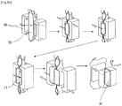
- the wall 36 of the pipe 34 is produced by extrusion blow molding. This technique consists in manufacturing a parison 55 which is then positioned and held in a mold 50. Air is injected (arrows F1) into the parison 55 so that it conforms to the shape of the internal cavity of the mold. After cooling, the preform obtained can undergo finishing operations as mentioned in the above.
- the parison material comprises cells which are obtained by injection of gas at the level of the extrusion screw.
- the expansion rate of the material varies in theory from 1.5 times to 3 times for PE and from 1.5 to 4 times for PP. This leads to final densities of between 200 and 400 kg / m 3 .
- the cells obtained by this process are closed and generally smaller in size than those obtained by the other process (use of two sheets).
- the pipes obtained by extrusion blow molding are denser and more rigid than those produced by the other process (sheet molding).
- the pipe 34 is then produced by carrying out step b) of mechanical punching of the wall 36, to form the pipe 34 according to the invention.
- the figure 9 illustrates an example of a mechanical punching tool 56.
- the wall 36 can be mounted between two jaws of the tool 56, each of these jaws comprising punches 58 configured to pierce or pierce the wall 36, as mentioned above.
- the pipe 34 Prior to punching, the pipe 34 is mounted on and along a support 59 which preferably has a shape complementary to the interior of the pipe.
- the wall 36 of the pipe 34 can be held fixedly on this support by suction or mechanical fixing.
- the punching of the pipe 34 can be done in one go by simultaneously moving the jaws on the pipe, or in two times (or more when there are more than two jaws), by moving the jaws one after the other.
- the movement of the jaws and of the tool can be carried out parallel to the same direction so that the microperforations are all substantially parallel.
- at least some microperforations could have a different orientation and the displacement of the jaws and of the tool would be carried out according to this orientation.
- the movement of the jaws and of the tool in general can be carried out electromechanically, hydraulically or automatically (by a robot for example).
- the punches 58 When the punches 58 are withdrawn from the wall 36 of the pipe, the pipe material will shrink by springback due to its elastic properties. The microperforations thus produced will then have transverse dimensions smaller than that of the punches 58.
- the punches 58 have the general shape of a point or of a needle, the free end of which can be tapered.
- only one of the jaws of the tool could be used to pierce the pipe and make the microperforations.
- This single jaw could be used to drill two opposite sides of the pipe. A first side of the pipe would be perforated, as mentioned in the above (from the outside to the inside of the pipe), and the jaw would be moved further towards the pipe so that its punches pass through the pipe and puncture the opposite side (from the inside to the outside).
- the microperforations would be made by laser drilling, by inserting a tool into the pipe and moving this tool from the inside to the outside of the pipe, etc.
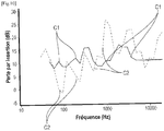
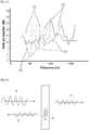
- the figure 10 is a graph showing the evolution of the acoustic attenuation in dB (called “insertion loss” according to the aforementioned standard) of pipes as a function of the frequency of a sound emission.
- Insertion Loss IL in dB
- IL in dB a difference in noise level observed at a point (or observation zone) between two configurations: one reference configuration (example: circuit with a conventional pipe), and a test configuration (circuit with the pipe according to the invention).
- a pipe typically exhibits a significant IL of 800 to 10,000Hz. Indeed, it can be seen that, at low frequencies (approximately 50 to 800Hz), curve C2 is below curve C1, which means that the acoustic attenuation obtained with the pipe does not meet the manufacturer's expectations.
- a pipe according to the invention can be defined as a dissipative silencer which allows a treatment dissipating the acoustic energy in or through its wall.
- the dissipation linked to the wall is quantified by its absorption.
- P D and P T are the amplitudes of the diffused and transmitted sound pressure.
- Attenuation in dB (IL for example): ⁇ 1.5 P S L ⁇ with P the treated perimeter of the section of the duct (m), S its section (m 2 ) and L the treated length.
- the performance therefore depends directly on the treated surface of the duct with significant absorption.
- the absorption of a wall can come from a part dissipated in the thickness of the wall but also by simple transparency.
- the absorption of a cell or foam wall should therefore be measured on a test setup allowing transmission through the wall.
- the complete balance (at normal incidence) is measured by following the method of standard ASTM E2611.
Landscapes
- Physics & Mathematics (AREA)
- Thermal Sciences (AREA)
- Engineering & Computer Science (AREA)
- Mechanical Engineering (AREA)
- Supports For Pipes And Cables (AREA)
- Crystals, And After-Treatments Of Crystals (AREA)
- Duct Arrangements (AREA)
Priority Applications (5)
| Application Number | Priority Date | Filing Date | Title |
|---|---|---|---|
| EP20305619.7A EP3922494B1 (de) | 2020-06-09 | 2020-06-09 | Luftverteilungsschlauch für einen hvac-kreislauf eines fahrzeugs |
| ES20305619T ES2946690T3 (es) | 2020-06-09 | 2020-06-09 | Tubo de distribución de aire para un circuito CVC de un vehículo |
| PCT/EP2021/060877 WO2021249688A1 (fr) | 2020-06-09 | 2021-04-26 | Tuyau de distribution d'air pour un circuit cvc d'un vehicule |
| CN202180042403.0A CN115702086A (zh) | 2020-06-09 | 2021-04-26 | 用于车辆的hvac回路的空气分配管 |
| EP21721096.2A EP4161789A1 (de) | 2020-06-09 | 2021-04-26 | Luftverteilungsrohr für einen cvc-kreis eines fahrzeugs |
Applications Claiming Priority (1)
| Application Number | Priority Date | Filing Date | Title |
|---|---|---|---|
| EP20305619.7A EP3922494B1 (de) | 2020-06-09 | 2020-06-09 | Luftverteilungsschlauch für einen hvac-kreislauf eines fahrzeugs |
Publications (2)
| Publication Number | Publication Date |
|---|---|
| EP3922494A1 true EP3922494A1 (de) | 2021-12-15 |
| EP3922494B1 EP3922494B1 (de) | 2023-04-05 |
Family
ID=71575273
Family Applications (2)
| Application Number | Title | Priority Date | Filing Date |
|---|---|---|---|
| EP20305619.7A Active EP3922494B1 (de) | 2020-06-09 | 2020-06-09 | Luftverteilungsschlauch für einen hvac-kreislauf eines fahrzeugs |
| EP21721096.2A Withdrawn EP4161789A1 (de) | 2020-06-09 | 2021-04-26 | Luftverteilungsrohr für einen cvc-kreis eines fahrzeugs |
Family Applications After (1)
| Application Number | Title | Priority Date | Filing Date |
|---|---|---|---|
| EP21721096.2A Withdrawn EP4161789A1 (de) | 2020-06-09 | 2021-04-26 | Luftverteilungsrohr für einen cvc-kreis eines fahrzeugs |
Country Status (4)
| Country | Link |
|---|---|
| EP (2) | EP3922494B1 (de) |
| CN (1) | CN115702086A (de) |
| ES (1) | ES2946690T3 (de) |
| WO (1) | WO2021249688A1 (de) |
Cited By (1)
| Publication number | Priority date | Publication date | Assignee | Title |
|---|---|---|---|---|
| DE202023102698U1 (de) | 2023-05-17 | 2023-06-12 | Mahle International Gmbh | Luftkanal |
Families Citing this family (1)
| Publication number | Priority date | Publication date | Assignee | Title |
|---|---|---|---|---|
| FR3162835A1 (fr) * | 2024-06-04 | 2025-12-05 | Stellantis Auto Sas | Dispositif d’aération présentant une patte de fixation à plusieurs conformations. |
Citations (4)
| Publication number | Priority date | Publication date | Assignee | Title |
|---|---|---|---|---|
| DE3536379A1 (de) * | 1985-10-11 | 1987-04-16 | Metzeler Schaum Gmbh | Luftfuehrungskanal, insbesondere in kraftfahrzeugen |
| JP2004116959A (ja) * | 2002-09-27 | 2004-04-15 | Jsp Corp | ダクト |
| FR2876172A1 (fr) * | 2004-10-01 | 2006-04-07 | Peugeot Citroen Automobiles Sa | Dispositif d'attenuation acoustique d'un conduit de ventilation d'un vehicule automobile et procede de realisation d'un tel dispositif |
| WO2008000788A1 (fr) * | 2006-06-29 | 2008-01-03 | Laboratoire De Recherches Et De Controle Du Caoutchouc Et Des Plastiques | Melange multiphasique a base de granulats d'elastomeres reticules dans une matrice polymerique a transformation thermoplastique. |
-
2020
- 2020-06-09 EP EP20305619.7A patent/EP3922494B1/de active Active
- 2020-06-09 ES ES20305619T patent/ES2946690T3/es active Active
-
2021
- 2021-04-26 WO PCT/EP2021/060877 patent/WO2021249688A1/fr not_active Ceased
- 2021-04-26 CN CN202180042403.0A patent/CN115702086A/zh active Pending
- 2021-04-26 EP EP21721096.2A patent/EP4161789A1/de not_active Withdrawn
Patent Citations (4)
| Publication number | Priority date | Publication date | Assignee | Title |
|---|---|---|---|---|
| DE3536379A1 (de) * | 1985-10-11 | 1987-04-16 | Metzeler Schaum Gmbh | Luftfuehrungskanal, insbesondere in kraftfahrzeugen |
| JP2004116959A (ja) * | 2002-09-27 | 2004-04-15 | Jsp Corp | ダクト |
| FR2876172A1 (fr) * | 2004-10-01 | 2006-04-07 | Peugeot Citroen Automobiles Sa | Dispositif d'attenuation acoustique d'un conduit de ventilation d'un vehicule automobile et procede de realisation d'un tel dispositif |
| WO2008000788A1 (fr) * | 2006-06-29 | 2008-01-03 | Laboratoire De Recherches Et De Controle Du Caoutchouc Et Des Plastiques | Melange multiphasique a base de granulats d'elastomeres reticules dans une matrice polymerique a transformation thermoplastique. |
Cited By (1)
| Publication number | Priority date | Publication date | Assignee | Title |
|---|---|---|---|---|
| DE202023102698U1 (de) | 2023-05-17 | 2023-06-12 | Mahle International Gmbh | Luftkanal |
Also Published As
| Publication number | Publication date |
|---|---|
| EP3922494B1 (de) | 2023-04-05 |
| ES2946690T3 (es) | 2023-07-24 |
| EP4161789A1 (de) | 2023-04-12 |
| WO2021249688A1 (fr) | 2021-12-16 |
| CN115702086A (zh) | 2023-02-14 |
Similar Documents
| Publication | Publication Date | Title |
|---|---|---|
| EP3993996B1 (de) | Schalldämmende beschichtung mit zellstruktur | |
| EP2763892B1 (de) | Verfahren zur herstellung einer schalldämmenden tafel | |
| CA2682306C (fr) | Procede de realisation d'une structure acoustiquement resistive, structure acoustiquement resistive ainsi obtenue et revetement utilisant une telle structure | |
| EP3922494B1 (de) | Luftverteilungsschlauch für einen hvac-kreislauf eines fahrzeugs | |
| EP3916717B1 (de) | Schalldämmende wabenstruktur mit einer membran, die mit einem rohr versehen ist, das für die verarbeitung verschiedener akustischer frequenzen konfiguriert ist, verfahren zur herstellung einer solchen schalldämmenden wabenstruktur und entsprechendes werkzeug | |
| WO2008113931A2 (fr) | Panneau acoustique | |
| EP2852495A1 (de) | Viskoelastische kunststoffzwischenschicht für vibroakustische dämpfung und verglasungseinheit mit solch einer zwischenschicht | |
| EP3534360A1 (de) | Schalldämmende beschichtung, die eine wabenstruktur mit gekrümmten zellen umfasst, die auf der einen und der anderen seite aus derselben innenwand gebildet werden | |
| FR3111002A1 (fr) | Procédé de fabrication d'une structure alvéolaire d’insonorisation incluant un diaphragme, et structure alvéolaire d’insonorisation obtenue | |
| WO2016102691A2 (fr) | Paroi acoustique à échangeur thermique intégré | |
| CA2707851A1 (fr) | Procede de jonction de panneaux acoustiques alveolaires | |
| FR3103054A1 (fr) | Panneau acoustique pour nacelle d’aéronef à absorption multifréquence. | |
| EP3792469A1 (de) | Lufteinlass, gondel, antriebseinheit und luftfahrzeug mit gerillter einlasslippe | |
| WO2018202973A1 (fr) | Conduit d'admission d'air poreux pour hvac | |
| FR3124016A1 (fr) | Panneau de traitement acoustique renforcé pour un ensemble propulsif d’aéronef | |
| EP2121384B1 (de) | Anordnung zur absorption von schallwellen | |
| EP4063703A1 (de) | Strömungsleitung für ein gasförmiges fluid mit einer schallabsorbierenden verkleidung | |
| FR2963280A1 (fr) | Dispositif attenuateur de l'intensite d'une perturbation acoustique et circuit de conditionnement d'air incluant un tel dispositif | |
| EP4133167A1 (de) | Optimiertes entladungsleitungsgitter und optimiertes entladungsventil | |
| EP4593005B1 (de) | Schallabsorbierende struktur mit einer wabenstruktur und mindestens einem teilerrohr, das mindestens zwei mit wänden der wabenstruktur verbundene platten aufweist | |
| FR2901738A1 (fr) | Dispositif reducteur de bruit pour circuit de climatisation de vehicule automobile, conduite et ce circuit l'incorporant | |
| EP4593006A1 (de) | Schallabsorbierende struktur mit mindestens einem teilerrohr zur bildung von zwei arten von resonatoren, verfahren zur herstellung einer solchen struktur | |
| FR3128775A1 (fr) | Conduit de diffusion d’air à performances acoustiques élevées, en particulier pour véhicule automobile | |
| WO2024209002A1 (fr) | Ecran de protection acoustique | |
| FR2917046A1 (fr) | "element de structure a caracteristique anti-bruit d'un vehicule automobile" |
Legal Events
| Date | Code | Title | Description |
|---|---|---|---|
| PUAI | Public reference made under article 153(3) epc to a published international application that has entered the european phase |
Free format text: ORIGINAL CODE: 0009012 |
|
| STAA | Information on the status of an ep patent application or granted ep patent |
Free format text: STATUS: THE APPLICATION HAS BEEN PUBLISHED |
|
| AK | Designated contracting states |
Kind code of ref document: A1 Designated state(s): AL AT BE BG CH CY CZ DE DK EE ES FI FR GB GR HR HU IE IS IT LI LT LU LV MC MK MT NL NO PL PT RO RS SE SI SK SM TR |
|
| B565 | Issuance of search results under rule 164(2) epc |
Effective date: 20201208 |
|
| STAA | Information on the status of an ep patent application or granted ep patent |
Free format text: STATUS: REQUEST FOR EXAMINATION WAS MADE |
|
| 17P | Request for examination filed |
Effective date: 20220608 |
|
| RBV | Designated contracting states (corrected) |
Designated state(s): AL AT BE BG CH CY CZ DE DK EE ES FI FR GB GR HR HU IE IS IT LI LT LU LV MC MK MT NL NO PL PT RO RS SE SI SK SM TR |
|
| GRAP | Despatch of communication of intention to grant a patent |
Free format text: ORIGINAL CODE: EPIDOSNIGR1 |
|
| STAA | Information on the status of an ep patent application or granted ep patent |
Free format text: STATUS: GRANT OF PATENT IS INTENDED |
|
| RIC1 | Information provided on ipc code assigned before grant |
Ipc: B60H 1/00 20060101AFI20220928BHEP |
|
| INTG | Intention to grant announced |
Effective date: 20221028 |
|
| GRAS | Grant fee paid |
Free format text: ORIGINAL CODE: EPIDOSNIGR3 |
|
| GRAA | (expected) grant |
Free format text: ORIGINAL CODE: 0009210 |
|
| STAA | Information on the status of an ep patent application or granted ep patent |
Free format text: STATUS: THE PATENT HAS BEEN GRANTED |
|
| AK | Designated contracting states |
Kind code of ref document: B1 Designated state(s): AL AT BE BG CH CY CZ DE DK EE ES FI FR GB GR HR HU IE IS IT LI LT LU LV MC MK MT NL NO PL PT RO RS SE SI SK SM TR |
|
| REG | Reference to a national code |
Ref country code: GB Ref legal event code: FG4D Free format text: NOT ENGLISH |
|
| REG | Reference to a national code |
Ref country code: CH Ref legal event code: EP |
|
| REG | Reference to a national code |
Ref country code: AT Ref legal event code: REF Ref document number: 1557968 Country of ref document: AT Kind code of ref document: T Effective date: 20230415 |
|
| REG | Reference to a national code |
Ref country code: DE Ref legal event code: R096 Ref document number: 602020009449 Country of ref document: DE |
|
| REG | Reference to a national code |
Ref country code: IE Ref legal event code: FG4D Free format text: LANGUAGE OF EP DOCUMENT: FRENCH |
|
| P01 | Opt-out of the competence of the unified patent court (upc) registered |
Effective date: 20230526 |
|
| REG | Reference to a national code |
Ref country code: ES Ref legal event code: FG2A Ref document number: 2946690 Country of ref document: ES Kind code of ref document: T3 Effective date: 20230724 |
|
| REG | Reference to a national code |
Ref country code: LT Ref legal event code: MG9D |
|
| REG | Reference to a national code |
Ref country code: NL Ref legal event code: MP Effective date: 20230405 |
|
| REG | Reference to a national code |
Ref country code: AT Ref legal event code: MK05 Ref document number: 1557968 Country of ref document: AT Kind code of ref document: T Effective date: 20230405 |
|
| PG25 | Lapsed in a contracting state [announced via postgrant information from national office to epo] |
Ref country code: NL Free format text: LAPSE BECAUSE OF FAILURE TO SUBMIT A TRANSLATION OF THE DESCRIPTION OR TO PAY THE FEE WITHIN THE PRESCRIBED TIME-LIMIT Effective date: 20230405 |
|
| PG25 | Lapsed in a contracting state [announced via postgrant information from national office to epo] |
Ref country code: SE Free format text: LAPSE BECAUSE OF FAILURE TO SUBMIT A TRANSLATION OF THE DESCRIPTION OR TO PAY THE FEE WITHIN THE PRESCRIBED TIME-LIMIT Effective date: 20230405 Ref country code: PT Free format text: LAPSE BECAUSE OF FAILURE TO SUBMIT A TRANSLATION OF THE DESCRIPTION OR TO PAY THE FEE WITHIN THE PRESCRIBED TIME-LIMIT Effective date: 20230807 Ref country code: NO Free format text: LAPSE BECAUSE OF FAILURE TO SUBMIT A TRANSLATION OF THE DESCRIPTION OR TO PAY THE FEE WITHIN THE PRESCRIBED TIME-LIMIT Effective date: 20230705 Ref country code: AT Free format text: LAPSE BECAUSE OF FAILURE TO SUBMIT A TRANSLATION OF THE DESCRIPTION OR TO PAY THE FEE WITHIN THE PRESCRIBED TIME-LIMIT Effective date: 20230405 |
|
| PG25 | Lapsed in a contracting state [announced via postgrant information from national office to epo] |
Ref country code: RS Free format text: LAPSE BECAUSE OF FAILURE TO SUBMIT A TRANSLATION OF THE DESCRIPTION OR TO PAY THE FEE WITHIN THE PRESCRIBED TIME-LIMIT Effective date: 20230405 Ref country code: PL Free format text: LAPSE BECAUSE OF FAILURE TO SUBMIT A TRANSLATION OF THE DESCRIPTION OR TO PAY THE FEE WITHIN THE PRESCRIBED TIME-LIMIT Effective date: 20230405 Ref country code: LV Free format text: LAPSE BECAUSE OF FAILURE TO SUBMIT A TRANSLATION OF THE DESCRIPTION OR TO PAY THE FEE WITHIN THE PRESCRIBED TIME-LIMIT Effective date: 20230405 Ref country code: LT Free format text: LAPSE BECAUSE OF FAILURE TO SUBMIT A TRANSLATION OF THE DESCRIPTION OR TO PAY THE FEE WITHIN THE PRESCRIBED TIME-LIMIT Effective date: 20230405 Ref country code: IS Free format text: LAPSE BECAUSE OF FAILURE TO SUBMIT A TRANSLATION OF THE DESCRIPTION OR TO PAY THE FEE WITHIN THE PRESCRIBED TIME-LIMIT Effective date: 20230805 Ref country code: HR Free format text: LAPSE BECAUSE OF FAILURE TO SUBMIT A TRANSLATION OF THE DESCRIPTION OR TO PAY THE FEE WITHIN THE PRESCRIBED TIME-LIMIT Effective date: 20230405 Ref country code: GR Free format text: LAPSE BECAUSE OF FAILURE TO SUBMIT A TRANSLATION OF THE DESCRIPTION OR TO PAY THE FEE WITHIN THE PRESCRIBED TIME-LIMIT Effective date: 20230706 Ref country code: AL Free format text: LAPSE BECAUSE OF FAILURE TO SUBMIT A TRANSLATION OF THE DESCRIPTION OR TO PAY THE FEE WITHIN THE PRESCRIBED TIME-LIMIT Effective date: 20230405 |
|
| PG25 | Lapsed in a contracting state [announced via postgrant information from national office to epo] |
Ref country code: FI Free format text: LAPSE BECAUSE OF FAILURE TO SUBMIT A TRANSLATION OF THE DESCRIPTION OR TO PAY THE FEE WITHIN THE PRESCRIBED TIME-LIMIT Effective date: 20230405 |
|
| REG | Reference to a national code |
Ref country code: DE Ref legal event code: R097 Ref document number: 602020009449 Country of ref document: DE |
|
| PG25 | Lapsed in a contracting state [announced via postgrant information from national office to epo] |
Ref country code: SK Free format text: LAPSE BECAUSE OF FAILURE TO SUBMIT A TRANSLATION OF THE DESCRIPTION OR TO PAY THE FEE WITHIN THE PRESCRIBED TIME-LIMIT Effective date: 20230405 |
|
| PG25 | Lapsed in a contracting state [announced via postgrant information from national office to epo] |
Ref country code: MC Free format text: LAPSE BECAUSE OF FAILURE TO SUBMIT A TRANSLATION OF THE DESCRIPTION OR TO PAY THE FEE WITHIN THE PRESCRIBED TIME-LIMIT Effective date: 20230405 |
|
| PG25 | Lapsed in a contracting state [announced via postgrant information from national office to epo] |
Ref country code: SM Free format text: LAPSE BECAUSE OF FAILURE TO SUBMIT A TRANSLATION OF THE DESCRIPTION OR TO PAY THE FEE WITHIN THE PRESCRIBED TIME-LIMIT Effective date: 20230405 Ref country code: SK Free format text: LAPSE BECAUSE OF FAILURE TO SUBMIT A TRANSLATION OF THE DESCRIPTION OR TO PAY THE FEE WITHIN THE PRESCRIBED TIME-LIMIT Effective date: 20230405 Ref country code: RO Free format text: LAPSE BECAUSE OF FAILURE TO SUBMIT A TRANSLATION OF THE DESCRIPTION OR TO PAY THE FEE WITHIN THE PRESCRIBED TIME-LIMIT Effective date: 20230405 Ref country code: MC Free format text: LAPSE BECAUSE OF FAILURE TO SUBMIT A TRANSLATION OF THE DESCRIPTION OR TO PAY THE FEE WITHIN THE PRESCRIBED TIME-LIMIT Effective date: 20230405 Ref country code: EE Free format text: LAPSE BECAUSE OF FAILURE TO SUBMIT A TRANSLATION OF THE DESCRIPTION OR TO PAY THE FEE WITHIN THE PRESCRIBED TIME-LIMIT Effective date: 20230405 Ref country code: DK Free format text: LAPSE BECAUSE OF FAILURE TO SUBMIT A TRANSLATION OF THE DESCRIPTION OR TO PAY THE FEE WITHIN THE PRESCRIBED TIME-LIMIT Effective date: 20230405 Ref country code: CZ Free format text: LAPSE BECAUSE OF FAILURE TO SUBMIT A TRANSLATION OF THE DESCRIPTION OR TO PAY THE FEE WITHIN THE PRESCRIBED TIME-LIMIT Effective date: 20230405 |
|
| REG | Reference to a national code |
Ref country code: CH Ref legal event code: PL |
|
| PLBE | No opposition filed within time limit |
Free format text: ORIGINAL CODE: 0009261 |
|
| STAA | Information on the status of an ep patent application or granted ep patent |
Free format text: STATUS: NO OPPOSITION FILED WITHIN TIME LIMIT |
|
| REG | Reference to a national code |
Ref country code: BE Ref legal event code: MM Effective date: 20230630 |
|
| PG25 | Lapsed in a contracting state [announced via postgrant information from national office to epo] |
Ref country code: LU Free format text: LAPSE BECAUSE OF NON-PAYMENT OF DUE FEES Effective date: 20230609 |
|
| 26N | No opposition filed |
Effective date: 20240108 |
|
| REG | Reference to a national code |
Ref country code: IE Ref legal event code: MM4A |
|
| PG25 | Lapsed in a contracting state [announced via postgrant information from national office to epo] |
Ref country code: LU Free format text: LAPSE BECAUSE OF NON-PAYMENT OF DUE FEES Effective date: 20230609 |
|
| PG25 | Lapsed in a contracting state [announced via postgrant information from national office to epo] |
Ref country code: IE Free format text: LAPSE BECAUSE OF NON-PAYMENT OF DUE FEES Effective date: 20230609 |
|
| PG25 | Lapsed in a contracting state [announced via postgrant information from national office to epo] |
Ref country code: IE Free format text: LAPSE BECAUSE OF NON-PAYMENT OF DUE FEES Effective date: 20230609 Ref country code: CH Free format text: LAPSE BECAUSE OF NON-PAYMENT OF DUE FEES Effective date: 20230630 |
|
| PG25 | Lapsed in a contracting state [announced via postgrant information from national office to epo] |
Ref country code: SI Free format text: LAPSE BECAUSE OF FAILURE TO SUBMIT A TRANSLATION OF THE DESCRIPTION OR TO PAY THE FEE WITHIN THE PRESCRIBED TIME-LIMIT Effective date: 20230405 |
|
| PG25 | Lapsed in a contracting state [announced via postgrant information from national office to epo] |
Ref country code: SI Free format text: LAPSE BECAUSE OF FAILURE TO SUBMIT A TRANSLATION OF THE DESCRIPTION OR TO PAY THE FEE WITHIN THE PRESCRIBED TIME-LIMIT Effective date: 20230405 Ref country code: BE Free format text: LAPSE BECAUSE OF NON-PAYMENT OF DUE FEES Effective date: 20230630 |
|
| PG25 | Lapsed in a contracting state [announced via postgrant information from national office to epo] |
Ref country code: BG Free format text: LAPSE BECAUSE OF FAILURE TO SUBMIT A TRANSLATION OF THE DESCRIPTION OR TO PAY THE FEE WITHIN THE PRESCRIBED TIME-LIMIT Effective date: 20230405 |
|
| PG25 | Lapsed in a contracting state [announced via postgrant information from national office to epo] |
Ref country code: BG Free format text: LAPSE BECAUSE OF FAILURE TO SUBMIT A TRANSLATION OF THE DESCRIPTION OR TO PAY THE FEE WITHIN THE PRESCRIBED TIME-LIMIT Effective date: 20230405 |
|
| GBPC | Gb: european patent ceased through non-payment of renewal fee |
Effective date: 20240609 |
|
| PG25 | Lapsed in a contracting state [announced via postgrant information from national office to epo] |
Ref country code: GB Free format text: LAPSE BECAUSE OF NON-PAYMENT OF DUE FEES Effective date: 20240609 |
|
| PGFP | Annual fee paid to national office [announced via postgrant information from national office to epo] |
Ref country code: DE Payment date: 20250618 Year of fee payment: 6 |
|
| PGFP | Annual fee paid to national office [announced via postgrant information from national office to epo] |
Ref country code: FR Payment date: 20250627 Year of fee payment: 6 |
|
| PG25 | Lapsed in a contracting state [announced via postgrant information from national office to epo] |
Ref country code: CY Free format text: LAPSE BECAUSE OF FAILURE TO SUBMIT A TRANSLATION OF THE DESCRIPTION OR TO PAY THE FEE WITHIN THE PRESCRIBED TIME-LIMIT; INVALID AB INITIO Effective date: 20200609 |
|
| PG25 | Lapsed in a contracting state [announced via postgrant information from national office to epo] |
Ref country code: HU Free format text: LAPSE BECAUSE OF FAILURE TO SUBMIT A TRANSLATION OF THE DESCRIPTION OR TO PAY THE FEE WITHIN THE PRESCRIBED TIME-LIMIT; INVALID AB INITIO Effective date: 20200609 |
|
| PGFP | Annual fee paid to national office [announced via postgrant information from national office to epo] |
Ref country code: ES Payment date: 20250731 Year of fee payment: 6 |
|
| PGFP | Annual fee paid to national office [announced via postgrant information from national office to epo] |
Ref country code: IT Payment date: 20250624 Year of fee payment: 6 |
|
| PG25 | Lapsed in a contracting state [announced via postgrant information from national office to epo] |
Ref country code: TR Free format text: LAPSE BECAUSE OF FAILURE TO SUBMIT A TRANSLATION OF THE DESCRIPTION OR TO PAY THE FEE WITHIN THE PRESCRIBED TIME-LIMIT Effective date: 20230405 |