EP3929606B1 - Système de gestion de batterie, bloc-batterie, véhicule électrique et procédé de gestion de batterie - Google Patents
Système de gestion de batterie, bloc-batterie, véhicule électrique et procédé de gestion de batterie Download PDFInfo
- Publication number
- EP3929606B1 EP3929606B1 EP20879744.9A EP20879744A EP3929606B1 EP 3929606 B1 EP3929606 B1 EP 3929606B1 EP 20879744 A EP20879744 A EP 20879744A EP 3929606 B1 EP3929606 B1 EP 3929606B1
- Authority
- EP
- European Patent Office
- Prior art keywords
- cell
- soc
- battery
- current
- group
- Prior art date
- Legal status (The legal status is an assumption and is not a legal conclusion. Google has not performed a legal analysis and makes no representation as to the accuracy of the status listed.)
- Active
Links
Images




Classifications
-
- B—PERFORMING OPERATIONS; TRANSPORTING
- B60—VEHICLES IN GENERAL
- B60L—PROPULSION OF ELECTRICALLY-PROPELLED VEHICLES; SUPPLYING ELECTRIC POWER FOR AUXILIARY EQUIPMENT OF ELECTRICALLY-PROPELLED VEHICLES; ELECTRODYNAMIC BRAKE SYSTEMS FOR VEHICLES IN GENERAL; MAGNETIC SUSPENSION OR LEVITATION FOR VEHICLES; MONITORING OPERATING VARIABLES OF ELECTRICALLY-PROPELLED VEHICLES; ELECTRIC SAFETY DEVICES FOR ELECTRICALLY-PROPELLED VEHICLES
- B60L3/00—Electric devices on electrically-propelled vehicles for safety purposes; Monitoring operating variables, e.g. speed, deceleration or energy consumption
- B60L3/0023—Detecting, eliminating, remedying or compensating for drive train abnormalities, e.g. failures within the drive train
- B60L3/0046—Detecting, eliminating, remedying or compensating for drive train abnormalities, e.g. failures within the drive train relating to electric energy storage systems, e.g. batteries or capacitors
-
- B—PERFORMING OPERATIONS; TRANSPORTING
- B60—VEHICLES IN GENERAL
- B60L—PROPULSION OF ELECTRICALLY-PROPELLED VEHICLES; SUPPLYING ELECTRIC POWER FOR AUXILIARY EQUIPMENT OF ELECTRICALLY-PROPELLED VEHICLES; ELECTRODYNAMIC BRAKE SYSTEMS FOR VEHICLES IN GENERAL; MAGNETIC SUSPENSION OR LEVITATION FOR VEHICLES; MONITORING OPERATING VARIABLES OF ELECTRICALLY-PROPELLED VEHICLES; ELECTRIC SAFETY DEVICES FOR ELECTRICALLY-PROPELLED VEHICLES
- B60L58/00—Methods or circuit arrangements for monitoring or controlling batteries or fuel cells, specially adapted for electric vehicles
- B60L58/10—Methods or circuit arrangements for monitoring or controlling batteries or fuel cells, specially adapted for electric vehicles for monitoring or controlling batteries
- B60L58/12—Methods or circuit arrangements for monitoring or controlling batteries or fuel cells, specially adapted for electric vehicles for monitoring or controlling batteries responding to state of charge [SoC]
-
- B—PERFORMING OPERATIONS; TRANSPORTING
- B60—VEHICLES IN GENERAL
- B60L—PROPULSION OF ELECTRICALLY-PROPELLED VEHICLES; SUPPLYING ELECTRIC POWER FOR AUXILIARY EQUIPMENT OF ELECTRICALLY-PROPELLED VEHICLES; ELECTRODYNAMIC BRAKE SYSTEMS FOR VEHICLES IN GENERAL; MAGNETIC SUSPENSION OR LEVITATION FOR VEHICLES; MONITORING OPERATING VARIABLES OF ELECTRICALLY-PROPELLED VEHICLES; ELECTRIC SAFETY DEVICES FOR ELECTRICALLY-PROPELLED VEHICLES
- B60L58/00—Methods or circuit arrangements for monitoring or controlling batteries or fuel cells, specially adapted for electric vehicles
- B60L58/10—Methods or circuit arrangements for monitoring or controlling batteries or fuel cells, specially adapted for electric vehicles for monitoring or controlling batteries
- B60L58/16—Methods or circuit arrangements for monitoring or controlling batteries or fuel cells, specially adapted for electric vehicles for monitoring or controlling batteries responding to battery ageing, e.g. to the number of charging cycles or the state of health [SoH]
-
- B—PERFORMING OPERATIONS; TRANSPORTING
- B60—VEHICLES IN GENERAL
- B60L—PROPULSION OF ELECTRICALLY-PROPELLED VEHICLES; SUPPLYING ELECTRIC POWER FOR AUXILIARY EQUIPMENT OF ELECTRICALLY-PROPELLED VEHICLES; ELECTRODYNAMIC BRAKE SYSTEMS FOR VEHICLES IN GENERAL; MAGNETIC SUSPENSION OR LEVITATION FOR VEHICLES; MONITORING OPERATING VARIABLES OF ELECTRICALLY-PROPELLED VEHICLES; ELECTRIC SAFETY DEVICES FOR ELECTRICALLY-PROPELLED VEHICLES
- B60L58/00—Methods or circuit arrangements for monitoring or controlling batteries or fuel cells, specially adapted for electric vehicles
- B60L58/10—Methods or circuit arrangements for monitoring or controlling batteries or fuel cells, specially adapted for electric vehicles for monitoring or controlling batteries
- B60L58/18—Methods or circuit arrangements for monitoring or controlling batteries or fuel cells, specially adapted for electric vehicles for monitoring or controlling batteries of two or more battery modules
-
- G—PHYSICS
- G01—MEASURING; TESTING
- G01R—MEASURING ELECTRIC VARIABLES; MEASURING MAGNETIC VARIABLES
- G01R31/00—Arrangements for testing electric properties; Arrangements for locating electric faults; Arrangements for electrical testing characterised by what is being tested not provided for elsewhere
- G01R31/36—Arrangements for testing, measuring or monitoring the electrical condition of accumulators or electric batteries, e.g. capacity or state of charge [SoC]
- G01R31/3644—Constructional arrangements
- G01R31/3648—Constructional arrangements comprising digital calculation means, e.g. for performing an algorithm
-
- G—PHYSICS
- G01—MEASURING; TESTING
- G01R—MEASURING ELECTRIC VARIABLES; MEASURING MAGNETIC VARIABLES
- G01R31/00—Arrangements for testing electric properties; Arrangements for locating electric faults; Arrangements for electrical testing characterised by what is being tested not provided for elsewhere
- G01R31/36—Arrangements for testing, measuring or monitoring the electrical condition of accumulators or electric batteries, e.g. capacity or state of charge [SoC]
- G01R31/367—Software therefor, e.g. for battery testing using modelling or look-up tables
-
- G—PHYSICS
- G01—MEASURING; TESTING
- G01R—MEASURING ELECTRIC VARIABLES; MEASURING MAGNETIC VARIABLES
- G01R31/00—Arrangements for testing electric properties; Arrangements for locating electric faults; Arrangements for electrical testing characterised by what is being tested not provided for elsewhere
- G01R31/36—Arrangements for testing, measuring or monitoring the electrical condition of accumulators or electric batteries, e.g. capacity or state of charge [SoC]
- G01R31/382—Arrangements for monitoring battery or accumulator variables, e.g. SoC
-
- G—PHYSICS
- G01—MEASURING; TESTING
- G01R—MEASURING ELECTRIC VARIABLES; MEASURING MAGNETIC VARIABLES
- G01R31/00—Arrangements for testing electric properties; Arrangements for locating electric faults; Arrangements for electrical testing characterised by what is being tested not provided for elsewhere
- G01R31/36—Arrangements for testing, measuring or monitoring the electrical condition of accumulators or electric batteries, e.g. capacity or state of charge [SoC]
- G01R31/382—Arrangements for monitoring battery or accumulator variables, e.g. SoC
- G01R31/3842—Arrangements for monitoring battery or accumulator variables, e.g. SoC combining voltage and current measurements
-
- G—PHYSICS
- G01—MEASURING; TESTING
- G01R—MEASURING ELECTRIC VARIABLES; MEASURING MAGNETIC VARIABLES
- G01R31/00—Arrangements for testing electric properties; Arrangements for locating electric faults; Arrangements for electrical testing characterised by what is being tested not provided for elsewhere
- G01R31/36—Arrangements for testing, measuring or monitoring the electrical condition of accumulators or electric batteries, e.g. capacity or state of charge [SoC]
- G01R31/385—Arrangements for measuring battery or accumulator variables
- G01R31/387—Determining ampere-hour charge capacity or SoC
-
- G—PHYSICS
- G01—MEASURING; TESTING
- G01R—MEASURING ELECTRIC VARIABLES; MEASURING MAGNETIC VARIABLES
- G01R31/00—Arrangements for testing electric properties; Arrangements for locating electric faults; Arrangements for electrical testing characterised by what is being tested not provided for elsewhere
- G01R31/36—Arrangements for testing, measuring or monitoring the electrical condition of accumulators or electric batteries, e.g. capacity or state of charge [SoC]
- G01R31/392—Determining battery ageing or deterioration, e.g. state of health
-
- G—PHYSICS
- G01—MEASURING; TESTING
- G01R—MEASURING ELECTRIC VARIABLES; MEASURING MAGNETIC VARIABLES
- G01R31/00—Arrangements for testing electric properties; Arrangements for locating electric faults; Arrangements for electrical testing characterised by what is being tested not provided for elsewhere
- G01R31/36—Arrangements for testing, measuring or monitoring the electrical condition of accumulators or electric batteries, e.g. capacity or state of charge [SoC]
- G01R31/396—Acquisition or processing of data for testing or for monitoring individual cells or groups of cells within a battery
-
- H—ELECTRICITY
- H01—ELECTRIC ELEMENTS
- H01M—PROCESSES OR MEANS, e.g. BATTERIES, FOR THE DIRECT CONVERSION OF CHEMICAL ENERGY INTO ELECTRICAL ENERGY
- H01M10/00—Secondary cells; Manufacture thereof
- H01M10/42—Methods or arrangements for servicing or maintenance of secondary cells or secondary half-cells
- H01M10/4207—Methods or arrangements for servicing or maintenance of secondary cells or secondary half-cells for several batteries or cells simultaneously or sequentially
-
- H—ELECTRICITY
- H01—ELECTRIC ELEMENTS
- H01M—PROCESSES OR MEANS, e.g. BATTERIES, FOR THE DIRECT CONVERSION OF CHEMICAL ENERGY INTO ELECTRICAL ENERGY
- H01M10/00—Secondary cells; Manufacture thereof
- H01M10/42—Methods or arrangements for servicing or maintenance of secondary cells or secondary half-cells
- H01M10/425—Structural combination with electronic components, e.g. electronic circuits integrated to the outside of the casing
-
- B—PERFORMING OPERATIONS; TRANSPORTING
- B60—VEHICLES IN GENERAL
- B60L—PROPULSION OF ELECTRICALLY-PROPELLED VEHICLES; SUPPLYING ELECTRIC POWER FOR AUXILIARY EQUIPMENT OF ELECTRICALLY-PROPELLED VEHICLES; ELECTRODYNAMIC BRAKE SYSTEMS FOR VEHICLES IN GENERAL; MAGNETIC SUSPENSION OR LEVITATION FOR VEHICLES; MONITORING OPERATING VARIABLES OF ELECTRICALLY-PROPELLED VEHICLES; ELECTRIC SAFETY DEVICES FOR ELECTRICALLY-PROPELLED VEHICLES
- B60L2240/00—Control parameters of input or output; Target parameters
- B60L2240/40—Drive Train control parameters
- B60L2240/54—Drive Train control parameters related to batteries
- B60L2240/547—Voltage
-
- B—PERFORMING OPERATIONS; TRANSPORTING
- B60—VEHICLES IN GENERAL
- B60L—PROPULSION OF ELECTRICALLY-PROPELLED VEHICLES; SUPPLYING ELECTRIC POWER FOR AUXILIARY EQUIPMENT OF ELECTRICALLY-PROPELLED VEHICLES; ELECTRODYNAMIC BRAKE SYSTEMS FOR VEHICLES IN GENERAL; MAGNETIC SUSPENSION OR LEVITATION FOR VEHICLES; MONITORING OPERATING VARIABLES OF ELECTRICALLY-PROPELLED VEHICLES; ELECTRIC SAFETY DEVICES FOR ELECTRICALLY-PROPELLED VEHICLES
- B60L2240/00—Control parameters of input or output; Target parameters
- B60L2240/40—Drive Train control parameters
- B60L2240/54—Drive Train control parameters related to batteries
- B60L2240/549—Current
-
- B—PERFORMING OPERATIONS; TRANSPORTING
- B60—VEHICLES IN GENERAL
- B60Y—INDEXING SCHEME RELATING TO ASPECTS CROSS-CUTTING VEHICLE TECHNOLOGY
- B60Y2200/00—Type of vehicle
- B60Y2200/90—Vehicles comprising electric prime movers
- B60Y2200/91—Electric vehicles
-
- H—ELECTRICITY
- H01—ELECTRIC ELEMENTS
- H01M—PROCESSES OR MEANS, e.g. BATTERIES, FOR THE DIRECT CONVERSION OF CHEMICAL ENERGY INTO ELECTRICAL ENERGY
- H01M10/00—Secondary cells; Manufacture thereof
- H01M10/42—Methods or arrangements for servicing or maintenance of secondary cells or secondary half-cells
- H01M10/425—Structural combination with electronic components, e.g. electronic circuits integrated to the outside of the casing
- H01M2010/4271—Battery management systems including electronic circuits, e.g. control of current or voltage to keep battery in healthy state, cell balancing
-
- Y—GENERAL TAGGING OF NEW TECHNOLOGICAL DEVELOPMENTS; GENERAL TAGGING OF CROSS-SECTIONAL TECHNOLOGIES SPANNING OVER SEVERAL SECTIONS OF THE IPC; TECHNICAL SUBJECTS COVERED BY FORMER USPC CROSS-REFERENCE ART COLLECTIONS [XRACs] AND DIGESTS
- Y02—TECHNOLOGIES OR APPLICATIONS FOR MITIGATION OR ADAPTATION AGAINST CLIMATE CHANGE
- Y02E—REDUCTION OF GREENHOUSE GAS [GHG] EMISSIONS, RELATED TO ENERGY GENERATION, TRANSMISSION OR DISTRIBUTION
- Y02E60/00—Enabling technologies; Technologies with a potential or indirect contribution to GHG emissions mitigation
- Y02E60/10—Energy storage using batteries
-
- Y—GENERAL TAGGING OF NEW TECHNOLOGICAL DEVELOPMENTS; GENERAL TAGGING OF CROSS-SECTIONAL TECHNOLOGIES SPANNING OVER SEVERAL SECTIONS OF THE IPC; TECHNICAL SUBJECTS COVERED BY FORMER USPC CROSS-REFERENCE ART COLLECTIONS [XRACs] AND DIGESTS
- Y02—TECHNOLOGIES OR APPLICATIONS FOR MITIGATION OR ADAPTATION AGAINST CLIMATE CHANGE
- Y02T—CLIMATE CHANGE MITIGATION TECHNOLOGIES RELATED TO TRANSPORTATION
- Y02T10/00—Road transport of goods or passengers
- Y02T10/60—Other road transportation technologies with climate change mitigation effect
- Y02T10/70—Energy storage systems for electromobility, e.g. batteries
Definitions
- the present disclosure relates to technology for estimating a State Of Charge (SOC) of each of a plurality of battery cells.
- SOC State Of Charge
- the SOC is a parameter indicating a relative ratio of the current capacity to the maximum capacity indicating electrical energy stored in the battery when the battery is fully charged, and may be represented as 0 ⁇ 1(or 0% ⁇ 100%). For example, when the maximum capacity of the battery is 1000 Ah (ampere-hour), and the capacity currently stored in the battery is 750 Ah, the SOC of the battery is 0.75 (or 75%).
- ampere counting and an equivalent circuit model are used to estimate the SOC of the battery.
- the ampere counting estimates the SOC of the battery based on the accumulated value of the electric current flowing through the battery.
- accuracy reduces as time goes by due to an error in current measurement.
- the equivalent circuit model is designed to simulate the electrical properties of the battery, and it is difficult to design the equivalent circuit model sufficiently simulating the nonlinear properties of the battery.
- US 7994755 B2 and US 10261134 B2 are related to battery state of charge estimation.
- the Kalman filter is a combined algorithm of the ampere counting and the equivalent circuit model, and can obtain the result of compensating for each disadvantage.
- a cell assembly including a few to a few tens of battery cells electrically connected in series is widely used.
- To safely use the cell assembly it is necessary to estimate the SOC of each of all the battery cells.
- the Kalman filter it is necessary to calculate the SOC as well as the polarization voltage, and thus when the Kalman filter according to the related art is applied to all the battery cells, the data processing rate is low and a very large data storage space is required.
- the present disclosure is designed to solve the above-described problem, and therefore the present disclosure is directed to a battery management system, a battery pack, an electric vehicle and a battery management method for effectively reducing the computational amount required for state of charge (SOC) estimation of each of all battery cells by grouping a plurality of battery cells and using a representative parameter (an average polarization voltage as described below) of each group as a common factor for estimating the SOC of each battery cell belonging to the corresponding group.
- SOC state of charge
- a battery management system includes a current measuring unit configured to measure a cell current flowing through a plurality of battery cells connected in series, a voltage measuring unit configured to measure a cell voltage of each battery cell, and a control unit operably coupled to the current measuring unit and the voltage measuring unit.
- the control unit is configured to classify the plurality of battery cells into at least one group based on a State Of Charge (SOC) of each battery cell estimated in a previous cycle.
- SOC State Of Charge
- the control unit is configured to estimate an average polarization voltage of a current cycle of each group based on an average SOC of the previous cycle, a first cell current and a second cell current of each group using a first Kalman filter.
- the first cell current denotes a cell current measured in the previous cycle
- the second cell current denotes a cell current measured in the current cycle.
- the control unit is configured to estimate the SOC of the current cycle of each battery cell, based on the first cell current, the second cell current and the average polarization voltage of the current cycle of each group, using a second Kalman filter.
- the control unit may be configured to classify the plurality of battery cells into at least one group so that a difference between a maximum SOC and a minimum SOC of each group is a threshold difference value or less.
- the control unit may be configured to determine the threshold difference value based on an average maximum capacity of the plurality of battery cells.
- the control unit may be configured to determine the threshold difference value to be equal to a first setting value when the average maximum capacity is equal to or larger than a threshold capacity.
- the control unit may be configured to determine the threshold difference value to be equal to a second setting value that is smaller than the first setting value, when the average maximum capacity is less than the threshold capacity.
- the control unit may be configured to classify the plurality of battery cells into at least one group by a threshold number in an order of magnitude of the SOC of each battery cell estimated in the previous cycle.
- the control unit may be configured to determine the threshold number based on an average maximum capacity of the plurality of battery cells.
- the control unit may be configured to determine the threshold number to be equal to a third setting value, when the average maximum capacity is equal to or larger than a threshold capacity.
- the control unit may be configured to determine the threshold number to be equal to a fourth setting value that is smaller than the third setting value, when the average maximum capacity is less than the threshold capacity.
- a battery pack according to another aspect of the present disclosure includes the battery management system.
- An electric vehicle includes the battery pack.
- a battery management method is for a plurality of battery cells connected in series.
- the battery management method includes classifying the plurality of battery cells into at least one group based on an SOC of each battery cell estimated in a previous cycle, estimating an average polarization voltage of a current cycle of each group, based on an average SOC of the previous cycle, a first cell current and a second cell current of each group, using a first Kalman filter, and estimating the SOC of the current cycle of each battery cell, based on the first cell current, the second cell current and the average polarization voltage of the current cycle of each group, using a second Kalman filter.
- the first cell current denotes a cell current measured in the previous cycle.
- the second cell current denotes a cell current measured in the current cycle.
- control unit refers to a processing unit of at least one function or operation, and may be implemented by hardware or software alone or in combination.
- FIG. 1 is a diagram exemplarily showing a configuration of an electric vehicle according to the present disclosure.
- the electric vehicle 1 includes a cell assembly 10, a relay 20, an inverter 30, an electric motor 40 and a battery management system 100.
- the cell assembly 10 is for providing electrical energy required to drive the electric vehicle 1.
- the cell assembly 10 includes a plurality of battery cells Cell 1 ⁇ Cell n (n is a natural number of 2 or greater) electrically in series connected between a positive terminal 11 and a negative terminal 12 of the cell assembly 10.
- Each battery cell Cell is not limited to a particular type, and includes any type of battery cell that can be repeatedly recharged, for example, a lithium ion cell.
- the relay 20 is installed on a current path for the charge and discharge of the cell assembly 10.
- the on/off of the relay 20 is controlled in response to a switching signal SS output by a control unit 120.
- the inverter 30 is provided to change the direct current from the cell assembly 10 to the alternating current in response to a command SD from the battery management system 100.
- the electric motor 40 is a 3-phase alternating-current motor, and operates with the alternating current generated by the inverter 30.
- the electric vehicle 1 runs by the driving power generated during the operation of the electric motor 40.
- the battery management system 100 is provided to be electrically connected to each battery cell Cell.
- the battery management system 100 includes a current measuring unit 111, a voltage measuring unit 112, the control unit 120 and a memory unit 130.
- the battery management system 100 may further include at least one of a temperature measuring unit 113 or a communication unit 140.
- the current measuring unit 111 is provided to be electrically connected to the current path.
- a shunt resistor or a hall effect device may be used as the current measuring unit 111.
- the current measuring unit 111 is configured to measure an electric current (hereinafter referred to as a 'cell current') flowing through the cell assembly 10, and output a first signal SI indicating the measured cell current to the control unit 120.
- the voltage measuring unit 112 includes at least one voltage sensor provided to be electrically connected to the positive terminal and the negative terminal of each battery cell Cell.
- the voltage measuring unit 112 is configured to measure a cell voltage which is a voltage across each battery cell Cell, and output a second signal SV indicating the measured cell voltage to the control unit 120.
- the temperature measuring unit 113 includes at least one temperature sensor T positioned within a predetermined distance from each battery cell Cell.
- a thermocouple may be used as the temperature sensor T.
- the temperature measuring unit 113 is configured to measure the temperature of each battery cell Cell, and output a third signal ST indicating the measured temperature to the control unit 120.
- the control unit 120 is operably coupled to the current measuring unit 111, the voltage measuring unit 112, the temperature measuring unit 113, the memory unit 130, the communication unit 140 and the relay 20.
- the control unit 120 may be implemented in hardware using at least one of application specific integrated circuits (ASICs), digital signal processors (DSPs), digital signal processing devices (DSPDs), programmable logic devices (PLDs), field programmable gate arrays (FPGAs), microprocessors or electrical units for performing other functions.
- ASICs application specific integrated circuits
- DSPs digital signal processors
- DSPDs digital signal processing devices
- PLDs programmable logic devices
- FPGAs field programmable gate arrays
- the control unit 120 is configured to periodically collect the first signal SI, the second signal SV and the third signal ST.
- the control unit 120 is configured to respectively determine the cell current, the cell voltage and the temperature from the first signal SI, the second signal SV and the third signal ST using an analog-to-digital (ADC) converter embedded therein, and store the determined values in the memory unit 130.
- ADC analog-to-digital
- the memory unit 130 is operably coupled to the control unit 120.
- the memory unit 130 may store programs and data necessary to perform the steps of the SOC estimation method according to embodiments as described below.
- the memory unit 130 may include, for example, at least type of storage medium of flash memory type, hard disk type, Solid State Disk (SSD) type, Silicon Disk Drive (SDD) type, multimedia card micro type, random access memory (RAM), static random access memory (SRAM), read-only memory (ROM), electrically erasable programmable read-only memory (EEPROM) or programmable read-only memory (PROM).
- the communication unit 140 may be coupled to an Electronic Control Unit (ECU) 2 of the electric vehicle 1 to enable communication.
- the communication unit 140 may transmit a vehicle message from the ECU 2 to the control unit 120, and a battery message from the control unit 120 to the ECU 2.
- the vehicle message may include information for notifying that the electric vehicle 1 is keyed on or off.
- the battery message may include information for notifying the SOC of each battery cell Cell.
- the communication between the communication unit 140 and the ECU 2 may use, for example, a wired network such as local area network (LAN), controller area network (CAN) and a daisy chain and/or a short-range wireless network such as Bluetooth, Zigbee and WiFi.
- SOC is indicated as the range between 0 and 1
- SOC 0 refers to fully discharged state
- SOC 1 refers to fully charged state
- 'U[k-1]' denotes a value of U of the previous cycle
- 'U[k]' denotes a value of U of the current cycle.
- the initial time point t 0 is a time point at which a preset event occurs, and for example, a time point at which the control unit 120 is changed from the sleep state to the wakeup state.
- the control unit 120 may be changed from the sleep state to the wakeup state in response to the key-on of the electric vehicle 1, and from the wakeup state to the sleep state in response to the key-off of the electric vehicle 1.
- Equation 1 represents the SOC of the battery cell Cell by ampere counting.
- SOC k SOC k ⁇ 1 + ⁇ t Q i I k ⁇ 1
- I[k-1] denotes the cell current measured in the previous cycle (referred to as a 'first cell current')
- Qi denotes the maximum capacity of the battery cell Cell
- SOC[k-1] denotes the SOC of the previous cycle
- SOC[k] denotes the SOC of the current cycle.
- I[0] 0 A.
- the maximum capacity Qi denotes the maximum amount of charges that can be stored in the battery cell Cell.
- the maximum capacity Qi may be equal to the accumulated value of the cell current during a period from the fully charged state to the fully discharged state of the battery.
- the equivalent circuit model 200 includes a voltage source 210, a resistance Ri and a RC pair R 2 , C 2 .
- the voltage source 210 simulates an open-circuited voltage (OCV) Vocv of the battery cell Cell kept in no load condition for a long term.
- OCV Vocv may be equal to the cell voltage of the battery cell Cell free of polarization voltage.
- the OCV-SOC curve may be preset for each of different temperatures.
- the resistance Ri is associated with an IR drop Vi of the battery cell Cell.
- the IR drop Vi refers to an instantaneous change in the voltage across the battery cell Cell by the cell current.
- the memory unit 130 may record a first lookup table defining a correspondence between the SOC and the temperature and the resistance R 1 , and the control unit 120 may determine the resistance R 1 corresponding to the SOC and the temperature of the current cycle from the first lookup table.
- the RC pair refers to a parallel circuit of the resistance R 2 and a capacitance C 2 , and is associated with the polarization voltage (also known as 'over potential') V P of the battery cell Cell.
- the time constant of the RC pair is the multiplication of the resistance R 2 and the capacitance C 2 .
- the memory unit 130 may record a second lookup table defining a correspondence between the SOC, the temperature and the resistance R 2 , and the control unit 120 may determine the resistance R 2 corresponding to the SOC and the temperature of the current cycle.
- the memory unit 130 may record a third lookup table defining a correspondence between the SOC, the temperature and the capacitance C 2 , and the control unit 120 may determine the capacitance C 2 corresponding to the SOC and the temperature of the current cycle from the third lookup table.
- V ecm is a variable indicating the voltage across the equivalent circuit model 200, and is equal to the sum of the OCV Vocv, the IR drop Vi and the polarization voltage V P as shown in the following Equation 2.
- Ri[k] is the resistance Ri of the current cycle
- I[k] is the cell current (referred to as a 'second cell current') measured in the current cycle.
- C[k] is a system matrix having the two components c[k] and 1.
- V P the polarization voltage V P may be defined as the following Equation 3.
- V P k V P k ⁇ 1 e ⁇ ⁇ t ⁇ + R 2 k ⁇ 1 I k ⁇ 1 1 ⁇ e ⁇ ⁇ t ⁇
- the control unit 120 classifies the plurality of battery cells Cell 1 ⁇ Cell n into at least one group based on the SOC of each battery cell Cell estimated in the previous cycle.
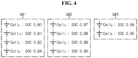
- FIG. 4 is a diagram for reference in describing a process of grouping the plurality of battery cells.
- the control unit 120 may group the first to tenth battery cells Cell 1 ⁇ Cell 10 so that a difference between the maximum SOC and the minimum SOC of each group is a threshold difference value or less on the basis of the minimum SOC of 0.80. For example, when the threshold difference value is preset to 0.06, as shown in FIG.
- control unit 120 may group the first to tenth battery cells Cell 1 ⁇ Cell 10 so that a difference between the maximum SOC and the minimum SOC of each group is the threshold difference value or less on the basis of the maximum SOC of 0.95.
- the threshold difference value is 0.06
- four battery cells having the SOC of 0.89, 0.90, 0.94 and 0.95 are classified as one group
- four battery cells having the SOC of 0.82, 0.84, 0.87, 0.88 are classified as another group
- two battery cells having the SOC of 0.80 and 0.81 are classified as the other group.
- the first to tenth battery cells Cell 1 ⁇ Cell 10 may be grouped by the threshold number in the order of magnitude of SOC.
- the threshold number is 3
- three battery cells having the SOC of 0.80, 0.81, 0.82 are classified as one group
- three battery cells having the SOC of 0.84, 0.87, 0.88 are classified as another group
- three battery cells having the SOC of 0.89, 0.90, 0.94 may be classified as a third group
- one battery cell having the SOC of 0.95 may be classified as the other group.
- the first to tenth battery cells Cell 1 ⁇ Cell 10 may be grouped by the threshold number in the descending order of SOC. For example, when the threshold number is 4, four battery cells having the SOC of 0.89, 0.90, 0.94, 0.95 are classified as one group, four battery cells having the SOC of 0.82, 0.84, 0.87, 0.88 are classified as another group, and two battery cells having the SOC of 0.80, 0.81 are classified as the other group.
- each parameter with the subscript ⁇ indicates a value predicted by time update. Additionally, each parameter with the superscript - indicates a value of a state variable corrected by measurement update.
- control unit 120 estimates the average SOC and the average polarization voltage of each group in the current cycle based on the average SOC of the previous cycle of each group, the first cell current and the second cell current, using a first Kalman filter.
- Equation 4 is a state equation of the first Kalman filter, and is associated with Equations 1 and 3.
- Equation 4 SOC av_ ⁇ [k-1] denotes the average SOC of each group in the previous cycle, V P_av_ ⁇ [k-1] denotes the average polarization voltage of each group in the previous cycle, Q av denotes the average maximum capacity of each group, ⁇ av denotes the average time constant of the RC pair of each group, and R 2_av [k-1] denotes the average of the resistance R 2 of the RC pair of each group in the previous cycle.
- the average time constant of each group may be multiplication of the resistance R 2 and the capacitance C 2 corresponding respectively to the average SOC and the average temperature of the battery cell(s) belonging to the same group.
- Equation 5 is a time update equation of the first Kalman filter.
- Equation 5 P[k-1] denotes a corrected error covariance matrix of the previous cycle, Q denotes a process noise covariance matrix, and P - [k] denotes an error covariance matrix of the current cycle.
- Wi may be a preset constant indicating the inaccuracy of ampere counting, and W 2 may be a preset constant indicating the inaccuracy of the equivalent circuit model.
- Equation 6 is a first measurement update equation of the first Kalman filter.
- K G k P ⁇ k C T k C k P ⁇ k C T k + L ⁇ 1
- K G [k] is a Kalman gain of the current cycle of each group
- C T [k] is a transposed matrix of C[k] (see Equation 2)
- L is a measurement noise covariance matrix having preset components.
- Equation 7 is a third measurement update equation of the first Kalman filter.
- P k E ⁇ K G k C k P ⁇ k
- Equation 7 E denotes a 2 ⁇ 2 unit matrix.
- P[k] is the result of correcting P - [k] from Equation 5 by Equation 7.
- Equation 8 is an output equation of the first Kalman filter
- Equation 9 is a second measurement update equation of the first Kalman filter.
- Equations 8 and 9 y[k] denotes the average cell voltage of each group measured in the current cycle, y ⁇ [k] denotes the average cell voltage of each group estimated in the current cycle, R 1_av [k] denotes the average of the resistance Ri of each group, SOC av_ ⁇ [k] denotes the average SOC of each group estimated in the current cycle, and V P_av_ ⁇ [k] denotes the average polarization voltage of each group estimated in the current cycle.
- x ⁇ [k] by Equation 9 may be used as x ⁇ [k-1] of Equation 4 in the next cycle.
- the SOC of each of all the battery cells Cell 1 ⁇ Cell n in the current cycle is estimated by performing the first Kalman filter once for each group and then performing a second Kalman filter on each battery cell Cell belonging to each group once.
- the second Kalman filter does not directly calculate the polarization voltage of each battery cell Cell in the current cycle, and makes use of the average polarization voltage of the current cycle determined by the first Kalman filter. Accordingly, calculation for updating the polarization voltage of each battery cell Cell is omitted from the second Kalman filter.
- Equation 10 is a state equation of the second Kalman filter.
- SOC i _ ⁇ ⁇ k SOC i _ ⁇ k ⁇ 1 + ⁇ t Q i i k ⁇ 1
- SOC i_ ⁇ [k-1] is the SOC of each battery cell Cell estimated in the previous cycle
- Qi is the maximum capacity of each battery cell Cell
- SOC - i_ ⁇ [k] is the SOC of each battery cell Cell estimated by the time update in the current cycle.
- SOC i_ ⁇ [0] f 2 (Vocv[0]).
- Vocv[0] is the voltage of each battery cell Cell measured at the initial time point to.
- Equation 12 is a first measurement update equation of the second Kalman filter.
- K i k s ⁇ k c k c k s ⁇ k c k + J
- Equation 12 K i [k] is a Kalman gain of the current cycle, and J is a measurement noise covariance. J may be the same as the first row-first column component of L of Equation 6.
- Equation 13 is a third measurement update equation of the second Kalman filter.
- Equation 13 s[k] is an error covariance of the current cycle, and the result of correcting s - [k] from Equation 11 by Equation 13.
- Equation 14 is an output equation of the second Kalman filter
- Equation 15 is a second measurement update equation of the second Kalman filter.
- V i _ ⁇ k c k SOC i _ ⁇ ⁇ k + V P _ av _ ⁇ k + R 1 _ i I k
- SOC i _ ⁇ k SOC i _ ⁇ ⁇ k + K i k V i k ⁇ V i _ ⁇ k
- V i [k] denotes the cell voltage of the battery cell Cell measured in the current cycle
- V i_ ⁇ [k] denotes the cell voltage of the battery cell Cell estimated by the time update in the current cycle
- R 1_i [k] denotes the resistance Ri of the battery cell Cell in the current cycle
- V P_av_ ⁇ [k] denotes the average polarization voltage of the current cycle of the group to which the battery cell Cell belongs
- SOC i_ ⁇ [k] denotes the SOC of the battery cell Cell estimated in the current cycle.
- V P_av_ ⁇ [k] of Equation 8 for the second group G#2 may be used as V P_av_ ⁇ [k] of Equation 14.
- SOC i_ ⁇ [k] by Equation 15 may be used as SOC i_ ⁇ [k-1] of Equation 10 in the next cycle.
- the control unit 120 may determine the maximum capacity Qi of each battery cell Cell, based on an accumulated value of the cell current for the capacity update period and the change in SOC of each battery cell Cell for the capacity update period, using the following Equation 16.
- ⁇ SOC is the change in SOC for the capacity update period
- ⁇ Q is the cell current accumulated value for the capacity update period
- a denotes the time index corresponding to the start time of the capacity update period
- b denotes the time index corresponding to the end time of the capacity update period.
- the maximum capacity reduces. Accordingly, when the degree of degradation of the battery cell Cell is above a predetermined level, it is a very high likelihood that the battery cell will suddenly become inoperable, and accordingly it is necessary to estimate the SOC more precisely.
- control unit 120 may determine the threshold difference value or the threshold number based on the average maximum capacity of the plurality of battery cells Cell 1 ⁇ Cell n .
- the threshold difference value when the average maximum capacity is equal to or larger than the threshold capacity (for example, 85% of the design capacity), the threshold difference value may be determined to be equal to a first setting value (for example, 0.06), and when the average maximum capacity is less than the threshold capacity, the threshold difference value may be determined to be equal to a second setting value (for example, 0.04) that is smaller than the first setting value.
- the threshold difference value reduces, the plurality of battery cells Cell 1 ⁇ Cell n may be classified into a larger number of groups, thereby estimating the SOC of each battery cell Cell more precisely.
- the threshold number when the average maximum capacity is equal to or larger than the threshold capacity, the threshold number may be determined to be equal to a third setting value (for example, 4), and when the average maximum capacity is less than the threshold capacity, the threshold number may be determined to be equal to a fourth setting value (for example, 3) that is smaller than the third setting value.
- a third setting value for example, 4
- a fourth setting value for example, 3
- the control unit 120 is initiated at the initial time point to at which the mode changes from the sleep mode to the wakeup mode in response to an occurrence of a preset event.
- the method according to each embodiment ends when the control unit 120 changes from the wakeup mode to the sleep mode.
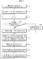
- FIG. 5 is a flowchart exemplarily showing an SOC estimation method according to a first embodiment of the present disclosure.
- step S510 the control unit 120 measures the cell current I[0] and the cell voltage V i [0] of each battery cell Cell.
- the cell current I[0] denotes the cell current measured for the first time from the initial time point to.
- the cell voltage V i [0] denotes the voltage of each battery cell Cell measured for the first time from the initial time point to.
- V i [0] Vocv[0].
- step S512 the control unit 120 determines the initial SOC SOC i_ ⁇ [0] of each battery cell Cell based on the cell voltage V i [0] of each battery cell Cell.
- step S520 the control unit 120 increases the time index k by 1.
- step S530 the control unit 120 classifies the plurality of battery cells Cell 1 ⁇ Cell n into at least one group so that a difference between the maximum SOC and the minimum SOC of each group is a predetermined value (for example, 0.06) or less based on SOC SOC i_ ⁇ [k-1] of each battery cell Cell estimated in the previous cycle.
- a predetermined value for example, 0.06
- step S540 the control unit 120 measures the cell current I[k] and the cell voltage V i [k] of each battery cell Cell.
- step S550 the control unit 120 estimates the average polarization voltage V P_av_ ⁇ [k] of the current cycle of each group using the first Kalman filter (see Equations 4 to 9).
- step S560 the control unit 120 estimates the SOC SOC i_ ⁇ [k] of the current cycle of each battery cell Cell of each group using the second Kalman filter (see Equations 10 to 15). After the step S560, the process may return to the step S520.
- FIG. 6 is a flowchart exemplarily showing an SOC estimation method according to a second embodiment of the present disclosure.
- step S610 the control unit 120 measures the cell current I[0] and the cell voltage V i [0] of each battery cell Cell.
- step S612 the control unit 120 determines the initial SOC SOC i_ ⁇ [0] of each battery cell Cell based on the cell voltage V i [0] of each battery cell Cell.
- step S620 the control unit 120 increases the time index k by 1.
- step S630 the control unit 120 determines whether the average maximum capacity Q av of the plurality of battery cells Cell 1 ⁇ Cell n is equal to or large r than the threshold capacity.
- the average maximum capacity Q av may be determined by the following Equation 17.
- Equation 17 Q i denotes the maximum capacity of the battery cell Cell i .
- step S642 the control unit 120 determines the threshold difference value to be equal to the first setting value.
- step S644 the control unit 120 determines the threshold difference value to be equal to the second setting value.
- the second setting value is smaller than the first setting value.
- step S650 the control unit 120 classifies the plurality of battery cells Cell 1 ⁇ Cell n into at least one group so that a difference between the maximum SOC and the minimum SOC of each group is the threshold difference value or less based on SOC SOC i_ ⁇ [k-1] of each battery cell Cell estimated in the previous cycle.
- step S660 the control unit 120 measures the cell current I[k] and the cell voltage V i [k] of each battery cell Cell.
- step S670 the control unit 120 estimates the average polarization voltage V P_av_ ⁇ [k] of the current cycle of each group using the first Kalman filter (see Equations 4 to 9).
- step S680 the control unit 120 estimates the SOC SOC i_ ⁇ [k] of the current cycle of each battery cell Cell of each group using the second Kalman filter (see Equations 10 to 15). After the step S680, the process may return to the step S620.
- FIG. 7 is a flowchart exemplarily showing an SOC estimation method according to a third embodiment of the present disclosure.
- step S710 the control unit 120 measures the cell current I[0] and the cell voltage V i [0] of each battery cell Cell.
- step S712 the control unit 120 determines the initial SOC SOC i_ ⁇ [0] of each battery cell Cell based on the cell voltage V i [0] of each battery cell Cell.
- step S720 the control unit 120 increases the time index k by 1.
- step S730 the control unit 120 determines whether the average maximum capacity Q av of the plurality of battery cells Cell 1 ⁇ Cell n is equal to or larger than the threshold capacity.
- step S742 is performed.
- step S744 is performed.
- step S742 the control unit 120 determines the threshold number to be equal to the third setting value.
- step S744 the control unit 120 determines the threshold number to be equal to the fourth setting value.
- the fourth setting value is smaller than the third setting value.
- step S750 the control unit 120 classifies the plurality of battery cells Cell 1 ⁇ Cell n into at least one group by the threshold number in the order of magnitude of the SOC SOC i_ ⁇ [k-1] of each battery cell Cell estimated in the previous cycle.
- step S760 the control unit 120 measures the current I[k] flowing through the plurality of battery cells Cell 1 ⁇ Cell n and the cell voltage V i [k] of each battery cell Cell.
- step S770 the control unit 120 estimates the average polarization voltage V P_av_ ⁇ [k] of the current cycle of each group using the first Kalman filter (see Equations 4 to 9).
- step S780 the control unit 120 estimates the SOC SOC i_ ⁇ [k] of the current cycle of each battery cell Cell of each group using the second Kalman filter (see Equations 10 to 15). After the step S780, the process may return to the step S720.
- the control unit 120 may turn off the relay 20.
- the control unit 120 may turn off the relay 20.
Landscapes
- Engineering & Computer Science (AREA)
- Physics & Mathematics (AREA)
- General Physics & Mathematics (AREA)
- Power Engineering (AREA)
- Transportation (AREA)
- Sustainable Energy (AREA)
- Sustainable Development (AREA)
- Mechanical Engineering (AREA)
- Life Sciences & Earth Sciences (AREA)
- Manufacturing & Machinery (AREA)
- Electrochemistry (AREA)
- Chemical & Material Sciences (AREA)
- General Chemical & Material Sciences (AREA)
- Chemical Kinetics & Catalysis (AREA)
- Microelectronics & Electronic Packaging (AREA)
- Secondary Cells (AREA)
- Tests Of Electric Status Of Batteries (AREA)
- Charge And Discharge Circuits For Batteries Or The Like (AREA)
- Electric Propulsion And Braking For Vehicles (AREA)
Claims (10)
- Système de gestion de batterie (100), comprenant :une unité de mesure de courant (111) configurée pour mesurer un courant de cellule circulant à travers une pluralité de cellules de batterie (10) connectées en série ;une unité de mesure de tension (112) configurée pour mesurer une tension de cellule de chaque cellule de batterie ; etune unité de commande (120) couplée de manière fonctionnelle à l'unité de mesure de courant et à l'unité de mesure de tension,le système de gestion de batterie étant caractérisé en ce que l'unité de commande est configurée pour :classer la pluralité de cellules de batterie en au moins un groupe sur la base d'un état de charge, SOC (de l'anglais « State Of Charge »), de chaque cellule de batterie estimé au cours d'un cycle précédent,estimer une tension de polarisation moyenne d'un cycle de courant de chaque groupe sur la base d'un SOC moyen du cycle précédent, d'un premier courant de cellule et d'un second courant de cellule de chaque groupe en utilisant un premier filtre de Kalman, le premier courant de cellule désignant un courant de cellule mesuré au cours du cycle précédent, et le second courant de cellule désignant un courant de cellule mesuré au cours du cycle actuel,estimer le SOC du cycle de courant de chaque cellule de batterie, sur la base du premier courant de cellule, du second courant de cellule et de la tension de polarisation moyenne du cycle de courant de chaque groupe, en utilisant un second filtre de Kalman.
- Système de gestion de batterie selon la revendication 1, l'unité de commande étant configurée pour classer la pluralité de cellules de batterie en au moins un groupe de sorte qu'une différence entre un SOC maximum et un SOC minimum de chaque groupe soit une valeur de différence de seuil ou moins.
- Système de gestion de batterie selon la revendication 2, l'unité de commande étant configurée pour déterminer la valeur de différence de seuil sur la base d'une capacité maximale moyenne de la pluralité de cellules de batterie.
- Système de gestion de batterie selon la revendication 3, l'unité de commande étant configurée pour :déterminer la valeur de différence de seuil comme étant égale à une première valeur de réglage, lorsque la capacité maximale moyenne est égale ou supérieure à une capacité seuil, etdéterminer la valeur de différence de seuil comme étant égale à une seconde valeur de réglage qui est plus petite que la première valeur de réglage, lorsque la capacité maximale moyenne est moindre que la capacité seuil.
- Système de gestion de batterie selon la revendication 1, l'unité de commande étant configurée pour classer la pluralité de cellules de batterie en au moins un groupe par un nombre de seuil dans un ordre de grandeur du SOC de chaque cellule de batterie estimé au cours du cycle précédent.
- Système de gestion de batterie selon la revendication 5, l'unité de commande étant configurée pour déterminer le nombre de seuil sur la base d'une capacité maximale moyenne de la pluralité de cellules de batterie.
- Système de gestion de batterie selon la revendication 6, l'unité de commande étant configurée pour :déterminer le nombre de seuil comme étant égal à une troisième valeur de réglage, lorsque la capacité maximale moyenne est égale ou supérieure à une capacité seuil, etdéterminer le nombre de seuil comme étant égal à une quatrième valeur de réglage qui est plus petite que la troisième valeur de réglage, lorsque la capacité maximale moyenne est moindre que la capacité seuil.
- Bloc-batterie comprenant le système de gestion de batterie selon l'une quelconque des revendications 1 à 7.
- Véhicule électrique comprenant le bloc-batterie selon la revendication 8.
- Procédé de gestion de batterie pour une pluralité de cellules de batterie connectées en série, le procédé de gestion de batterie étant caractérisé par :le classement de la pluralité de cellules de batterie en au moins un groupe sur la base d'un état de charge, SOC (de l'anglais « State Of Charge »), de chaque cellule de batterie estimé au cours d'un cycle précédent ;l'estimation d'une tension de polarisation moyenne d'un cycle de courant de chaque groupe, sur la base d'un SOC moyen du cycle précédent, d'un premier courant de cellule et d'un second courant de cellule de chaque groupe, en utilisant un premier filtre de Kalman ; etl'estimation du SOC du cycle de courant de chaque cellule de batterie, sur la base du premier courant de cellule, du second courant de cellule et de la tension de polarisation moyenne du cycle de courant de chaque groupe, en utilisant un second filtre de Kalman,le premier courant de cellule désignant un courant de cellule mesuré au cours du cycle précédent, etle second courant de cellule désignant un courant de cellule mesuré au cours du cycle actuel.
Applications Claiming Priority (2)
| Application Number | Priority Date | Filing Date | Title |
|---|---|---|---|
| KR1020190133525A KR102809114B1 (ko) | 2019-10-25 | 2019-10-25 | 배터리의 soc를 추정하기 위한 장치, 그것을 포함하는 전기 차량 및 그 방법 |
| PCT/KR2020/011775 WO2021080161A1 (fr) | 2019-10-25 | 2020-09-02 | Système de gestion de batterie, bloc-batterie, véhicule électrique et procédé de gestion de batterie |
Publications (3)
| Publication Number | Publication Date |
|---|---|
| EP3929606A1 EP3929606A1 (fr) | 2021-12-29 |
| EP3929606A4 EP3929606A4 (fr) | 2022-06-15 |
| EP3929606B1 true EP3929606B1 (fr) | 2022-11-09 |
Family
ID=75619880
Family Applications (1)
| Application Number | Title | Priority Date | Filing Date |
|---|---|---|---|
| EP20879744.9A Active EP3929606B1 (fr) | 2019-10-25 | 2020-09-02 | Système de gestion de batterie, bloc-batterie, véhicule électrique et procédé de gestion de batterie |
Country Status (7)
| Country | Link |
|---|---|
| US (1) | US12122262B2 (fr) |
| EP (1) | EP3929606B1 (fr) |
| JP (1) | JP7226723B2 (fr) |
| KR (1) | KR102809114B1 (fr) |
| CN (1) | CN113748352B (fr) |
| PL (1) | PL3929606T3 (fr) |
| WO (1) | WO2021080161A1 (fr) |
Cited By (1)
| Publication number | Priority date | Publication date | Assignee | Title |
|---|---|---|---|---|
| DE102024104467B3 (de) | 2024-01-03 | 2025-06-05 | GM Global Technology Operations LLC | Batteriezellenzustandsbewertung basierend auf ladezustandsabweichung |
Families Citing this family (13)
| Publication number | Priority date | Publication date | Assignee | Title |
|---|---|---|---|---|
| US12095056B2 (en) * | 2020-09-07 | 2024-09-17 | Hyundai Motor Company | Battery management apparatus and energy storage system having the same |
| US12241943B2 (en) * | 2021-07-14 | 2025-03-04 | GM Global Technology Operations LLC | Method for early detection of an internal short in a battery pack |
| KR102776820B1 (ko) | 2021-11-01 | 2025-03-10 | 한국전자기술연구원 | 슬레이브 모듈, 이를 구비하는 배터리 관리 시스템, 및 배터리 상태 추정 방법 |
| US12202374B2 (en) * | 2021-11-01 | 2025-01-21 | GM Global Technology Operations LLC | Health monitoring methods for early fault detection in high voltage battery packs used in electric vehicles |
| CN116409203B (zh) * | 2021-12-30 | 2025-09-09 | 比亚迪股份有限公司 | 电池的管理方法及管理装置、车辆及计算机可读存储介质 |
| KR102698009B1 (ko) * | 2022-10-26 | 2024-08-21 | 주식회사 엘지에너지솔루션 | 배터리 진단 장치 및 방법 |
| KR20240069500A (ko) * | 2022-11-11 | 2024-05-20 | 주식회사 엘지에너지솔루션 | 배터리 이상 진단 장치 및 이의 동작 방법 |
| KR20240069502A (ko) * | 2022-11-11 | 2024-05-20 | 주식회사 엘지에너지솔루션 | 배터리 이상 진단 장치 및 이의 동작 방법 |
| KR102885247B1 (ko) * | 2023-06-26 | 2025-11-11 | 주식회사 엘지에너지솔루션 | 배터리 관리 시스템, 배터리 팩, 전기 차량 및 배터리 관리 방법 |
| KR20250048932A (ko) * | 2023-10-04 | 2025-04-11 | 현대자동차주식회사 | 차량의 고전압 배터리의 모니터링 방법 |
| KR20250151914A (ko) * | 2024-04-15 | 2025-10-22 | 삼성에스디아이 주식회사 | 복합 확률 변수 기반 배터리 상태 추정 방법 및 시스템 |
| CN118376930B (zh) * | 2024-06-26 | 2024-08-23 | 西南科技大学 | 一种储能锂电池电压功能状态评估方法及其系统 |
| US20260077729A1 (en) * | 2024-09-18 | 2026-03-19 | Volvo Car Corporation | System and method for managing battery power drain |
Family Cites Families (27)
| Publication number | Priority date | Publication date | Assignee | Title |
|---|---|---|---|---|
| JP3849541B2 (ja) | 2002-02-20 | 2006-11-22 | トヨタ自動車株式会社 | 組電池の充放電制御方法 |
| US7994755B2 (en) * | 2008-01-30 | 2011-08-09 | Lg Chem, Ltd. | System, method, and article of manufacture for determining an estimated battery cell module state |
| JP5073601B2 (ja) | 2008-07-10 | 2012-11-14 | 株式会社オートネットワーク技術研究所 | バッテリの状態推定方法及び電源装置 |
| CN102062841B (zh) | 2009-11-11 | 2012-12-12 | 北汽福田汽车股份有限公司 | 动力电池荷电状态的估测方法及系统 |
| JP5595361B2 (ja) * | 2011-09-27 | 2014-09-24 | プライムアースEvエナジー株式会社 | 二次電池の充電状態推定装置 |
| JP5798067B2 (ja) | 2012-03-13 | 2015-10-21 | プライムアースEvエナジー株式会社 | 二次電池の状態推定装置 |
| KR101908412B1 (ko) * | 2012-03-29 | 2018-10-17 | 에스케이이노베이션 주식회사 | 배터리 관리 시스템 및 그 시스템의 soc 값 보정 방법 |
| US8972091B2 (en) | 2013-03-12 | 2015-03-03 | Ford Global Technologies, Llc | Reduced central processing unit load and memory usage battery state of charge calculation |
| US9588184B2 (en) | 2013-04-30 | 2017-03-07 | Nuvera Fuel Cells, Inc. | Battery state-of-charge aggregation method |
| US10345386B2 (en) | 2014-03-03 | 2019-07-09 | Panasonic Intellectual Property Management Co., Ltd. | Battery state estimation device and method of estimating battery state |
| KR101767635B1 (ko) * | 2014-10-24 | 2017-08-14 | 주식회사 엘지화학 | 이차 전지의 충전 상태 추정 장치 및 그 방법 |
| FR3029299B1 (fr) | 2014-11-28 | 2016-12-09 | Renault Sa | Procede automatique de determination de l'etat de charge d'une batterie |
| CN105738815B (zh) | 2014-12-12 | 2019-10-22 | 国家电网公司 | 一种在线检测锂离子电池健康状态的方法 |
| KR102441335B1 (ko) | 2015-08-13 | 2022-09-06 | 삼성전자주식회사 | 배터리의 soc 추정 장치 및 방법 |
| JP6414558B2 (ja) * | 2016-02-01 | 2018-10-31 | 株式会社デンソー | 電池状態推定装置 |
| US9960625B2 (en) | 2016-03-31 | 2018-05-01 | Robert Bosch Gmbh | Battery management system with multiple observers |
| KR102179677B1 (ko) | 2017-04-12 | 2020-11-17 | 주식회사 엘지화학 | 노이즈를 반영한 배터리 잔존 용량 산출 장치 및 방법 |
| EP3435101A1 (fr) | 2017-07-26 | 2019-01-30 | INVENOX GmbH | Procédé et dispositif de surveillance d'un comportement convergent stable d'un filtre de kalman |
| KR102160274B1 (ko) * | 2017-09-07 | 2020-09-25 | 주식회사 엘지화학 | 배터리 충전 상태 추정 장치 및 방법 |
| KR101946784B1 (ko) | 2017-09-29 | 2019-02-12 | 한국과학기술원 | 칼만 필터를 이용하여 배터리의 엔트로피를 측정하는 방법 |
| KR20190065758A (ko) | 2017-12-04 | 2019-06-12 | 삼성전자주식회사 | 배터리 교정을 위한 전자 장치 및 그 동작 방법 |
| US20190170826A1 (en) | 2017-12-06 | 2019-06-06 | Cadex Electronics Inc. | Battery state-of-health determination upon charging |
| US20190190091A1 (en) | 2017-12-18 | 2019-06-20 | Samsung Electronics Co., Ltd. | Method and apparatus estimating a state of battery |
| KR20190073236A (ko) * | 2017-12-18 | 2019-06-26 | 삼성전자주식회사 | 배터리 상태 추정 방법 및 장치 |
| KR102349235B1 (ko) * | 2018-02-14 | 2022-01-07 | 주식회사 엘지에너지솔루션 | 배터리의 충전 상태를 추정하기 위한 장치 및 방법 |
| KR20190133525A (ko) | 2018-05-23 | 2019-12-03 | 주식회사 썬라이즈 | 색칠 기능을 갖는 공작용 점토 조성물 및 그 제조방법 |
| CN109669132B (zh) * | 2019-01-21 | 2020-09-22 | 西北工业大学 | 一种基于变分贝叶斯滤波的电池荷电状态估计方法 |
-
2019
- 2019-10-25 KR KR1020190133525A patent/KR102809114B1/ko active Active
-
2020
- 2020-09-02 US US17/438,805 patent/US12122262B2/en active Active
- 2020-09-02 WO PCT/KR2020/011775 patent/WO2021080161A1/fr not_active Ceased
- 2020-09-02 PL PL20879744.9T patent/PL3929606T3/pl unknown
- 2020-09-02 EP EP20879744.9A patent/EP3929606B1/fr active Active
- 2020-09-02 CN CN202080031914.8A patent/CN113748352B/zh active Active
- 2020-09-02 JP JP2021549286A patent/JP7226723B2/ja active Active
Cited By (1)
| Publication number | Priority date | Publication date | Assignee | Title |
|---|---|---|---|---|
| DE102024104467B3 (de) | 2024-01-03 | 2025-06-05 | GM Global Technology Operations LLC | Batteriezellenzustandsbewertung basierend auf ladezustandsabweichung |
Also Published As
| Publication number | Publication date |
|---|---|
| WO2021080161A1 (fr) | 2021-04-29 |
| US12122262B2 (en) | 2024-10-22 |
| KR102809114B1 (ko) | 2025-05-15 |
| PL3929606T3 (pl) | 2023-01-30 |
| CN113748352B (zh) | 2024-01-26 |
| US20220176845A1 (en) | 2022-06-09 |
| EP3929606A4 (fr) | 2022-06-15 |
| EP3929606A1 (fr) | 2021-12-29 |
| JP7226723B2 (ja) | 2023-02-21 |
| CN113748352A (zh) | 2021-12-03 |
| JP2022536437A (ja) | 2022-08-17 |
| KR20210049338A (ko) | 2021-05-06 |
Similar Documents
| Publication | Publication Date | Title |
|---|---|---|
| EP3929606B1 (fr) | Système de gestion de batterie, bloc-batterie, véhicule électrique et procédé de gestion de batterie | |
| US11567137B2 (en) | Battery management system, battery management method, battery pack and electric vehicle | |
| EP4202464B1 (fr) | Système de gestion de batterie, bloc-batterie, véhicule électrique et procédé de gestion de batterie | |
| EP3828567B1 (fr) | Dispositif de gestion de batterie, procédé de gestion de batterie et bloc-batterie | |
| JP6844090B2 (ja) | バッテリーのための等価回路モデルのパラメータを推定する方法及びバッテリー管理システム | |
| EP3828568B1 (fr) | Appareil de gestion de batterie, procédé de gestion de batterie et batterie | |
| US12320862B2 (en) | Battery management system, battery pack, energy storage system and battery management method | |
| JP6896965B2 (ja) | バッテリーのための等価回路モデルのパラメータ推定方法及びバッテリー管理システム | |
| US20250070281A1 (en) | Battery Management System, Battery Pack, Electric Vehicle and Battery Charging Time Prediction Method | |
| EP3982138B1 (fr) | Dispositif de diagnostic de batterie, procédé de diagnostic de batterie et système de stockage d'énergie | |
| EP3805768B1 (fr) | Appareil de gestion de batterie, procédé de gestion de batterie et bloc-batterie | |
| JP2023527137A (ja) | バッテリー診断装置、バッテリー診断方法、バッテリーパック及び電気車両 | |
| EP3872507B1 (fr) | Système de gestion de batterie, procédé de gestion de batterie, bloc-batterie et véhicule électrique |
Legal Events
| Date | Code | Title | Description |
|---|---|---|---|
| STAA | Information on the status of an ep patent application or granted ep patent |
Free format text: STATUS: THE INTERNATIONAL PUBLICATION HAS BEEN MADE |
|
| PUAI | Public reference made under article 153(3) epc to a published international application that has entered the european phase |
Free format text: ORIGINAL CODE: 0009012 |
|
| STAA | Information on the status of an ep patent application or granted ep patent |
Free format text: STATUS: REQUEST FOR EXAMINATION WAS MADE |
|
| 17P | Request for examination filed |
Effective date: 20210923 |
|
| AK | Designated contracting states |
Kind code of ref document: A1 Designated state(s): AL AT BE BG CH CY CZ DE DK EE ES FI FR GB GR HR HU IE IS IT LI LT LU LV MC MK MT NL NO PL PT RO RS SE SI SK SM TR |
|
| RAP3 | Party data changed (applicant data changed or rights of an application transferred) |
Owner name: LG ENERGY SOLUTION, LTD. |
|
| A4 | Supplementary search report drawn up and despatched |
Effective date: 20220516 |
|
| RIC1 | Information provided on ipc code assigned before grant |
Ipc: B60L 3/00 20190101ALI20220510BHEP Ipc: G01R 31/3842 20190101ALI20220510BHEP Ipc: B60L 58/12 20190101ALI20220510BHEP Ipc: G01R 31/396 20190101ALI20220510BHEP Ipc: G01R 15/04 20060101ALI20220510BHEP Ipc: G01R 19/00 20060101ALI20220510BHEP Ipc: G01R 19/10 20060101ALI20220510BHEP Ipc: G01R 19/165 20060101ALI20220510BHEP Ipc: G01R 31/36 20200101ALI20220510BHEP Ipc: G01R 31/367 20190101AFI20220510BHEP |
|
| GRAP | Despatch of communication of intention to grant a patent |
Free format text: ORIGINAL CODE: EPIDOSNIGR1 |
|
| STAA | Information on the status of an ep patent application or granted ep patent |
Free format text: STATUS: GRANT OF PATENT IS INTENDED |
|
| RIC1 | Information provided on ipc code assigned before grant |
Ipc: B60L 3/00 20190101ALI20220710BHEP Ipc: G01R 31/3842 20190101ALI20220710BHEP Ipc: B60L 58/12 20190101ALI20220710BHEP Ipc: G01R 31/396 20190101ALI20220710BHEP Ipc: G01R 15/04 20060101ALI20220710BHEP Ipc: G01R 19/00 20060101ALI20220710BHEP Ipc: G01R 19/10 20060101ALI20220710BHEP Ipc: G01R 19/165 20060101ALI20220710BHEP Ipc: G01R 31/36 20200101ALI20220710BHEP Ipc: G01R 31/367 20190101AFI20220710BHEP |
|
| DAV | Request for validation of the european patent (deleted) | ||
| DAX | Request for extension of the european patent (deleted) | ||
| INTG | Intention to grant announced |
Effective date: 20220726 |
|
| GRAS | Grant fee paid |
Free format text: ORIGINAL CODE: EPIDOSNIGR3 |
|
| GRAA | (expected) grant |
Free format text: ORIGINAL CODE: 0009210 |
|
| STAA | Information on the status of an ep patent application or granted ep patent |
Free format text: STATUS: THE PATENT HAS BEEN GRANTED |
|
| AK | Designated contracting states |
Kind code of ref document: B1 Designated state(s): AL AT BE BG CH CY CZ DE DK EE ES FI FR GB GR HR HU IE IS IT LI LT LU LV MC MK MT NL NO PL PT RO RS SE SI SK SM TR |
|
| REG | Reference to a national code |
Ref country code: GB Ref legal event code: FG4D |
|
| REG | Reference to a national code |
Ref country code: CH Ref legal event code: EP Ref country code: AT Ref legal event code: REF Ref document number: 1530718 Country of ref document: AT Kind code of ref document: T Effective date: 20221115 |
|
| REG | Reference to a national code |
Ref country code: DE Ref legal event code: R096 Ref document number: 602020006218 Country of ref document: DE |
|
| REG | Reference to a national code |
Ref country code: IE Ref legal event code: FG4D |
|
| REG | Reference to a national code |
Ref country code: SE Ref legal event code: TRGR |
|
| REG | Reference to a national code |
Ref country code: LT Ref legal event code: MG9D |
|
| REG | Reference to a national code |
Ref country code: NL Ref legal event code: MP Effective date: 20221109 |
|
| REG | Reference to a national code |
Ref country code: AT Ref legal event code: MK05 Ref document number: 1530718 Country of ref document: AT Kind code of ref document: T Effective date: 20221109 |
|
| PG25 | Lapsed in a contracting state [announced via postgrant information from national office to epo] |
Ref country code: PT Free format text: LAPSE BECAUSE OF FAILURE TO SUBMIT A TRANSLATION OF THE DESCRIPTION OR TO PAY THE FEE WITHIN THE PRESCRIBED TIME-LIMIT Effective date: 20230309 Ref country code: NO Free format text: LAPSE BECAUSE OF FAILURE TO SUBMIT A TRANSLATION OF THE DESCRIPTION OR TO PAY THE FEE WITHIN THE PRESCRIBED TIME-LIMIT Effective date: 20230209 Ref country code: LT Free format text: LAPSE BECAUSE OF FAILURE TO SUBMIT A TRANSLATION OF THE DESCRIPTION OR TO PAY THE FEE WITHIN THE PRESCRIBED TIME-LIMIT Effective date: 20221109 Ref country code: FI Free format text: LAPSE BECAUSE OF FAILURE TO SUBMIT A TRANSLATION OF THE DESCRIPTION OR TO PAY THE FEE WITHIN THE PRESCRIBED TIME-LIMIT Effective date: 20221109 Ref country code: ES Free format text: LAPSE BECAUSE OF FAILURE TO SUBMIT A TRANSLATION OF THE DESCRIPTION OR TO PAY THE FEE WITHIN THE PRESCRIBED TIME-LIMIT Effective date: 20221109 Ref country code: AT Free format text: LAPSE BECAUSE OF FAILURE TO SUBMIT A TRANSLATION OF THE DESCRIPTION OR TO PAY THE FEE WITHIN THE PRESCRIBED TIME-LIMIT Effective date: 20221109 |
|
| PG25 | Lapsed in a contracting state [announced via postgrant information from national office to epo] |
Ref country code: RS Free format text: LAPSE BECAUSE OF FAILURE TO SUBMIT A TRANSLATION OF THE DESCRIPTION OR TO PAY THE FEE WITHIN THE PRESCRIBED TIME-LIMIT Effective date: 20221109 Ref country code: LV Free format text: LAPSE BECAUSE OF FAILURE TO SUBMIT A TRANSLATION OF THE DESCRIPTION OR TO PAY THE FEE WITHIN THE PRESCRIBED TIME-LIMIT Effective date: 20221109 Ref country code: IS Free format text: LAPSE BECAUSE OF FAILURE TO SUBMIT A TRANSLATION OF THE DESCRIPTION OR TO PAY THE FEE WITHIN THE PRESCRIBED TIME-LIMIT Effective date: 20230309 Ref country code: HR Free format text: LAPSE BECAUSE OF FAILURE TO SUBMIT A TRANSLATION OF THE DESCRIPTION OR TO PAY THE FEE WITHIN THE PRESCRIBED TIME-LIMIT Effective date: 20221109 Ref country code: GR Free format text: LAPSE BECAUSE OF FAILURE TO SUBMIT A TRANSLATION OF THE DESCRIPTION OR TO PAY THE FEE WITHIN THE PRESCRIBED TIME-LIMIT Effective date: 20230210 |
|
| P01 | Opt-out of the competence of the unified patent court (upc) registered |
Effective date: 20230512 |
|
| PG25 | Lapsed in a contracting state [announced via postgrant information from national office to epo] |
Ref country code: NL Free format text: LAPSE BECAUSE OF FAILURE TO SUBMIT A TRANSLATION OF THE DESCRIPTION OR TO PAY THE FEE WITHIN THE PRESCRIBED TIME-LIMIT Effective date: 20221109 |
|
| PG25 | Lapsed in a contracting state [announced via postgrant information from national office to epo] |
Ref country code: SM Free format text: LAPSE BECAUSE OF FAILURE TO SUBMIT A TRANSLATION OF THE DESCRIPTION OR TO PAY THE FEE WITHIN THE PRESCRIBED TIME-LIMIT Effective date: 20221109 Ref country code: RO Free format text: LAPSE BECAUSE OF FAILURE TO SUBMIT A TRANSLATION OF THE DESCRIPTION OR TO PAY THE FEE WITHIN THE PRESCRIBED TIME-LIMIT Effective date: 20221109 Ref country code: EE Free format text: LAPSE BECAUSE OF FAILURE TO SUBMIT A TRANSLATION OF THE DESCRIPTION OR TO PAY THE FEE WITHIN THE PRESCRIBED TIME-LIMIT Effective date: 20221109 Ref country code: DK Free format text: LAPSE BECAUSE OF FAILURE TO SUBMIT A TRANSLATION OF THE DESCRIPTION OR TO PAY THE FEE WITHIN THE PRESCRIBED TIME-LIMIT Effective date: 20221109 Ref country code: CZ Free format text: LAPSE BECAUSE OF FAILURE TO SUBMIT A TRANSLATION OF THE DESCRIPTION OR TO PAY THE FEE WITHIN THE PRESCRIBED TIME-LIMIT Effective date: 20221109 |
|
| REG | Reference to a national code |
Ref country code: DE Ref legal event code: R097 Ref document number: 602020006218 Country of ref document: DE |
|
| PG25 | Lapsed in a contracting state [announced via postgrant information from national office to epo] |
Ref country code: SK Free format text: LAPSE BECAUSE OF FAILURE TO SUBMIT A TRANSLATION OF THE DESCRIPTION OR TO PAY THE FEE WITHIN THE PRESCRIBED TIME-LIMIT Effective date: 20221109 Ref country code: AL Free format text: LAPSE BECAUSE OF FAILURE TO SUBMIT A TRANSLATION OF THE DESCRIPTION OR TO PAY THE FEE WITHIN THE PRESCRIBED TIME-LIMIT Effective date: 20221109 |
|
| PLBE | No opposition filed within time limit |
Free format text: ORIGINAL CODE: 0009261 |
|
| STAA | Information on the status of an ep patent application or granted ep patent |
Free format text: STATUS: NO OPPOSITION FILED WITHIN TIME LIMIT |
|
| 26N | No opposition filed |
Effective date: 20230810 |
|
| PG25 | Lapsed in a contracting state [announced via postgrant information from national office to epo] |
Ref country code: SI Free format text: LAPSE BECAUSE OF FAILURE TO SUBMIT A TRANSLATION OF THE DESCRIPTION OR TO PAY THE FEE WITHIN THE PRESCRIBED TIME-LIMIT Effective date: 20221109 |
|
| REG | Reference to a national code |
Ref country code: CH Ref legal event code: PL |
|
| PG25 | Lapsed in a contracting state [announced via postgrant information from national office to epo] |
Ref country code: LU Free format text: LAPSE BECAUSE OF NON-PAYMENT OF DUE FEES Effective date: 20230902 |
|
| REG | Reference to a national code |
Ref country code: BE Ref legal event code: MM Effective date: 20230930 |
|
| PG25 | Lapsed in a contracting state [announced via postgrant information from national office to epo] |
Ref country code: LU Free format text: LAPSE BECAUSE OF NON-PAYMENT OF DUE FEES Effective date: 20230902 Ref country code: IT Free format text: LAPSE BECAUSE OF FAILURE TO SUBMIT A TRANSLATION OF THE DESCRIPTION OR TO PAY THE FEE WITHIN THE PRESCRIBED TIME-LIMIT Effective date: 20221109 Ref country code: MC Free format text: LAPSE BECAUSE OF FAILURE TO SUBMIT A TRANSLATION OF THE DESCRIPTION OR TO PAY THE FEE WITHIN THE PRESCRIBED TIME-LIMIT Effective date: 20221109 |
|
| REG | Reference to a national code |
Ref country code: IE Ref legal event code: MM4A |
|
| PG25 | Lapsed in a contracting state [announced via postgrant information from national office to epo] |
Ref country code: IE Free format text: LAPSE BECAUSE OF NON-PAYMENT OF DUE FEES Effective date: 20230902 |
|
| PG25 | Lapsed in a contracting state [announced via postgrant information from national office to epo] |
Ref country code: CH Free format text: LAPSE BECAUSE OF NON-PAYMENT OF DUE FEES Effective date: 20230930 |
|
| PG25 | Lapsed in a contracting state [announced via postgrant information from national office to epo] |
Ref country code: IE Free format text: LAPSE BECAUSE OF NON-PAYMENT OF DUE FEES Effective date: 20230902 Ref country code: CH Free format text: LAPSE BECAUSE OF NON-PAYMENT OF DUE FEES Effective date: 20230930 |
|
| PG25 | Lapsed in a contracting state [announced via postgrant information from national office to epo] |
Ref country code: BE Free format text: LAPSE BECAUSE OF NON-PAYMENT OF DUE FEES Effective date: 20230930 |
|
| PG25 | Lapsed in a contracting state [announced via postgrant information from national office to epo] |
Ref country code: BG Free format text: LAPSE BECAUSE OF FAILURE TO SUBMIT A TRANSLATION OF THE DESCRIPTION OR TO PAY THE FEE WITHIN THE PRESCRIBED TIME-LIMIT Effective date: 20221109 |
|
| PG25 | Lapsed in a contracting state [announced via postgrant information from national office to epo] |
Ref country code: BG Free format text: LAPSE BECAUSE OF FAILURE TO SUBMIT A TRANSLATION OF THE DESCRIPTION OR TO PAY THE FEE WITHIN THE PRESCRIBED TIME-LIMIT Effective date: 20221109 |
|
| PG25 | Lapsed in a contracting state [announced via postgrant information from national office to epo] |
Ref country code: CY Free format text: LAPSE BECAUSE OF FAILURE TO SUBMIT A TRANSLATION OF THE DESCRIPTION OR TO PAY THE FEE WITHIN THE PRESCRIBED TIME-LIMIT; INVALID AB INITIO Effective date: 20200902 |
|
| PG25 | Lapsed in a contracting state [announced via postgrant information from national office to epo] |
Ref country code: HU Free format text: LAPSE BECAUSE OF FAILURE TO SUBMIT A TRANSLATION OF THE DESCRIPTION OR TO PAY THE FEE WITHIN THE PRESCRIBED TIME-LIMIT; INVALID AB INITIO Effective date: 20200902 |
|
| PGFP | Annual fee paid to national office [announced via postgrant information from national office to epo] |
Ref country code: DE Payment date: 20250820 Year of fee payment: 6 |
|
| PGFP | Annual fee paid to national office [announced via postgrant information from national office to epo] |
Ref country code: PL Payment date: 20250822 Year of fee payment: 6 |
|
| PGFP | Annual fee paid to national office [announced via postgrant information from national office to epo] |
Ref country code: GB Payment date: 20250820 Year of fee payment: 6 |
|
| PGFP | Annual fee paid to national office [announced via postgrant information from national office to epo] |
Ref country code: FR Payment date: 20250821 Year of fee payment: 6 |
|
| PGFP | Annual fee paid to national office [announced via postgrant information from national office to epo] |
Ref country code: SE Payment date: 20250821 Year of fee payment: 6 |
|
| PG25 | Lapsed in a contracting state [announced via postgrant information from national office to epo] |
Ref country code: TR Free format text: LAPSE BECAUSE OF FAILURE TO SUBMIT A TRANSLATION OF THE DESCRIPTION OR TO PAY THE FEE WITHIN THE PRESCRIBED TIME-LIMIT Effective date: 20221109 |