EP3931096B1 - Équilibrage de couple pour systèmes de propulsion électrique hybrides et aéronef utilisant des systèmes de propulsion électrique hybrides - Google Patents
Équilibrage de couple pour systèmes de propulsion électrique hybrides et aéronef utilisant des systèmes de propulsion électrique hybrides Download PDFInfo
- Publication number
- EP3931096B1 EP3931096B1 EP19918266.8A EP19918266A EP3931096B1 EP 3931096 B1 EP3931096 B1 EP 3931096B1 EP 19918266 A EP19918266 A EP 19918266A EP 3931096 B1 EP3931096 B1 EP 3931096B1
- Authority
- EP
- European Patent Office
- Prior art keywords
- torque
- heat engine
- electric motor
- total
- module
- Prior art date
- Legal status (The legal status is an assumption and is not a legal conclusion. Google has not performed a legal analysis and makes no representation as to the accuracy of the status listed.)
- Active
Links
Images


Classifications
-
- B—PERFORMING OPERATIONS; TRANSPORTING
- B64—AIRCRAFT; AVIATION; COSMONAUTICS
- B64D—EQUIPMENT FOR FITTING IN OR TO AIRCRAFT; FLIGHT SUITS; PARACHUTES; ARRANGEMENT OR MOUNTING OF POWER PLANTS OR PROPULSION TRANSMISSIONS IN AIRCRAFT
- B64D27/00—Arrangement or mounting of power plants in aircraft; Aircraft characterised by the type or position of power plants
- B64D27/02—Aircraft characterised by the type or position of power plants
- B64D27/10—Aircraft characterised by the type or position of power plants of gas-turbine type
- B64D27/12—Aircraft characterised by the type or position of power plants of gas-turbine type within, or attached to, wings
-
- B—PERFORMING OPERATIONS; TRANSPORTING
- B60—VEHICLES IN GENERAL
- B60W—CONJOINT CONTROL OF VEHICLE SUB-UNITS OF DIFFERENT TYPE OR DIFFERENT FUNCTION; CONTROL SYSTEMS SPECIALLY ADAPTED FOR HYBRID VEHICLES; ROAD VEHICLE DRIVE CONTROL SYSTEMS FOR PURPOSES NOT RELATED TO THE CONTROL OF A PARTICULAR SUB-UNIT
- B60W10/00—Conjoint control of vehicle sub-units of different type or different function
- B60W10/04—Conjoint control of vehicle sub-units of different type or different function including control of propulsion units
-
- B—PERFORMING OPERATIONS; TRANSPORTING
- B64—AIRCRAFT; AVIATION; COSMONAUTICS
- B64D—EQUIPMENT FOR FITTING IN OR TO AIRCRAFT; FLIGHT SUITS; PARACHUTES; ARRANGEMENT OR MOUNTING OF POWER PLANTS OR PROPULSION TRANSMISSIONS IN AIRCRAFT
- B64D27/00—Arrangement or mounting of power plants in aircraft; Aircraft characterised by the type or position of power plants
- B64D27/02—Aircraft characterised by the type or position of power plants
- B64D27/10—Aircraft characterised by the type or position of power plants of gas-turbine type
-
- B—PERFORMING OPERATIONS; TRANSPORTING
- B64—AIRCRAFT; AVIATION; COSMONAUTICS
- B64D—EQUIPMENT FOR FITTING IN OR TO AIRCRAFT; FLIGHT SUITS; PARACHUTES; ARRANGEMENT OR MOUNTING OF POWER PLANTS OR PROPULSION TRANSMISSIONS IN AIRCRAFT
- B64D27/00—Arrangement or mounting of power plants in aircraft; Aircraft characterised by the type or position of power plants
- B64D27/02—Aircraft characterised by the type or position of power plants
- B64D27/30—Aircraft characterised by electric power plants
- B64D27/33—Hybrid electric aircraft
-
- B—PERFORMING OPERATIONS; TRANSPORTING
- B64—AIRCRAFT; AVIATION; COSMONAUTICS
- B64D—EQUIPMENT FOR FITTING IN OR TO AIRCRAFT; FLIGHT SUITS; PARACHUTES; ARRANGEMENT OR MOUNTING OF POWER PLANTS OR PROPULSION TRANSMISSIONS IN AIRCRAFT
- B64D31/00—Power plant control systems; Arrangement of power plant control systems in aircraft
- B64D31/02—Initiating means
- B64D31/06—Initiating means actuated automatically
- B64D31/12—Initiating means actuated automatically for equalising or synchronising power plants
-
- B—PERFORMING OPERATIONS; TRANSPORTING
- B64—AIRCRAFT; AVIATION; COSMONAUTICS
- B64D—EQUIPMENT FOR FITTING IN OR TO AIRCRAFT; FLIGHT SUITS; PARACHUTES; ARRANGEMENT OR MOUNTING OF POWER PLANTS OR PROPULSION TRANSMISSIONS IN AIRCRAFT
- B64D31/00—Power plant control systems; Arrangement of power plant control systems in aircraft
- B64D31/16—Power plant control systems; Arrangement of power plant control systems in aircraft for electric power plants
- B64D31/18—Power plant control systems; Arrangement of power plant control systems in aircraft for electric power plants for hybrid-electric power plants
-
- F—MECHANICAL ENGINEERING; LIGHTING; HEATING; WEAPONS; BLASTING
- F02—COMBUSTION ENGINES; HOT-GAS OR COMBUSTION-PRODUCT ENGINE PLANTS
- F02C—GAS-TURBINE PLANTS; AIR INTAKES FOR JET-PROPULSION PLANTS; CONTROLLING FUEL SUPPLY IN AIR-BREATHING JET-PROPULSION PLANTS
- F02C6/00—Plural gas-turbine plants; Combinations of gas-turbine plants with other apparatus; Adaptations of gas-turbine plants for special use
- F02C6/20—Adaptations of gas-turbine plants for driving vehicles
- F02C6/206—Adaptations of gas-turbine plants for driving vehicles the vehicles being airscrew driven
-
- F—MECHANICAL ENGINEERING; LIGHTING; HEATING; WEAPONS; BLASTING
- F02—COMBUSTION ENGINES; HOT-GAS OR COMBUSTION-PRODUCT ENGINE PLANTS
- F02C—GAS-TURBINE PLANTS; AIR INTAKES FOR JET-PROPULSION PLANTS; CONTROLLING FUEL SUPPLY IN AIR-BREATHING JET-PROPULSION PLANTS
- F02C7/00—Features, components parts, details or accessories, not provided for in, or of interest apart form groups F02C1/00 - F02C6/00; Air intakes for jet-propulsion plants
- F02C7/22—Fuel supply systems
-
- F—MECHANICAL ENGINEERING; LIGHTING; HEATING; WEAPONS; BLASTING
- F02—COMBUSTION ENGINES; HOT-GAS OR COMBUSTION-PRODUCT ENGINE PLANTS
- F02C—GAS-TURBINE PLANTS; AIR INTAKES FOR JET-PROPULSION PLANTS; CONTROLLING FUEL SUPPLY IN AIR-BREATHING JET-PROPULSION PLANTS
- F02C9/00—Controlling gas-turbine plants; Controlling fuel supply in air- breathing jet-propulsion plants
- F02C9/26—Control of fuel supply
-
- F—MECHANICAL ENGINEERING; LIGHTING; HEATING; WEAPONS; BLASTING
- F02—COMBUSTION ENGINES; HOT-GAS OR COMBUSTION-PRODUCT ENGINE PLANTS
- F02C—GAS-TURBINE PLANTS; AIR INTAKES FOR JET-PROPULSION PLANTS; CONTROLLING FUEL SUPPLY IN AIR-BREATHING JET-PROPULSION PLANTS
- F02C9/00—Controlling gas-turbine plants; Controlling fuel supply in air- breathing jet-propulsion plants
- F02C9/26—Control of fuel supply
- F02C9/42—Control of fuel supply specially adapted for the control of two or more plants simultaneously
-
- F—MECHANICAL ENGINEERING; LIGHTING; HEATING; WEAPONS; BLASTING
- F02—COMBUSTION ENGINES; HOT-GAS OR COMBUSTION-PRODUCT ENGINE PLANTS
- F02K—JET-PROPULSION PLANTS
- F02K5/00—Plants including an engine, other than a gas turbine, driving a compressor or a ducted fan
-
- B—PERFORMING OPERATIONS; TRANSPORTING
- B64—AIRCRAFT; AVIATION; COSMONAUTICS
- B64D—EQUIPMENT FOR FITTING IN OR TO AIRCRAFT; FLIGHT SUITS; PARACHUTES; ARRANGEMENT OR MOUNTING OF POWER PLANTS OR PROPULSION TRANSMISSIONS IN AIRCRAFT
- B64D27/00—Arrangement or mounting of power plants in aircraft; Aircraft characterised by the type or position of power plants
- B64D27/02—Aircraft characterised by the type or position of power plants
- B64D27/026—Aircraft characterised by the type or position of power plants comprising different types of power plants, e.g. combination of a piston engine and a gas-turbine
-
- B—PERFORMING OPERATIONS; TRANSPORTING
- B64—AIRCRAFT; AVIATION; COSMONAUTICS
- B64D—EQUIPMENT FOR FITTING IN OR TO AIRCRAFT; FLIGHT SUITS; PARACHUTES; ARRANGEMENT OR MOUNTING OF POWER PLANTS OR PROPULSION TRANSMISSIONS IN AIRCRAFT
- B64D27/00—Arrangement or mounting of power plants in aircraft; Aircraft characterised by the type or position of power plants
- B64D27/02—Aircraft characterised by the type or position of power plants
- B64D27/30—Aircraft characterised by electric power plants
- B64D27/31—Aircraft characterised by electric power plants within, or attached to, wings
-
- F—MECHANICAL ENGINEERING; LIGHTING; HEATING; WEAPONS; BLASTING
- F05—INDEXING SCHEMES RELATING TO ENGINES OR PUMPS IN VARIOUS SUBCLASSES OF CLASSES F01-F04
- F05D—INDEXING SCHEME FOR ASPECTS RELATING TO NON-POSITIVE-DISPLACEMENT MACHINES OR ENGINES, GAS-TURBINES OR JET-PROPULSION PLANTS
- F05D2270/00—Control
- F05D2270/30—Control parameters, e.g. input parameters
- F05D2270/335—Output power or torque
-
- Y—GENERAL TAGGING OF NEW TECHNOLOGICAL DEVELOPMENTS; GENERAL TAGGING OF CROSS-SECTIONAL TECHNOLOGIES SPANNING OVER SEVERAL SECTIONS OF THE IPC; TECHNICAL SUBJECTS COVERED BY FORMER USPC CROSS-REFERENCE ART COLLECTIONS [XRACs] AND DIGESTS
- Y02—TECHNOLOGIES OR APPLICATIONS FOR MITIGATION OR ADAPTATION AGAINST CLIMATE CHANGE
- Y02T—CLIMATE CHANGE MITIGATION TECHNOLOGIES RELATED TO TRANSPORTATION
- Y02T50/00—Aeronautics or air transport
- Y02T50/60—Efficient propulsion technologies, e.g. for aircraft
Definitions
- This disclosure relates to aircraft and engines therefor, and more particularly to hybrid electric aircraft engines.
- Aircraft engines vary in efficiency and function over a plurality of parameters, such as thrust requirements, air temperature, air speed, altitude, and the like. Aircraft require the most thrust at takeoff, wherein the demand for engine power is the heaviest. However, during the remainder of the mission, the aircraft engines often do not require as much thrust as during takeoff. The size and weight of the engines allows them to produce the power needed for takeoff, however after take-off the engines are in effect over-sized for the relatively low power required to produce thrust for cruising in level flight.
- US 2018/346139 A1 discloses a hybrid electric engine control module according to the preamble of claim 1.
- US 2019/001955 A1 discloses a propulsion system for an aircraft.
- the present invention provides a hybrid electric engine control module (ECU) as set forth in claim 1.
- ECU electric engine control module
- the present invention also provides a computer implemented hybrid electric aircraft powerplant control method as set forth in claim 9.
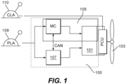
- FIG. 1 an illustrative view of an embodiment of a powerplant system in accordance with the disclosure is shown in Fig. 1 and is designated generally by reference character 100.
- FIGs. 2-3B Other embodiments and/or aspects of this disclosure are shown in Figs. 2-3B .
- a hybrid electric aircraft powerplant (HEP) system 100 can include a heat engine system 101 configured to provide torque to an air mover 103 (e.g., a propeller, fan, or any other suitable propulsion device).
- the heat engine of the HEP 100 can be a heat engine of any type, e.g., a gas turbine, spark ignited, diesel, rotary, or reciprocating engine of any fuel type and with any configuration.
- Any suitable heat engine system can include any suitable turbomachinery elements, either turbocharger, turbosupercharger, supercharger, and exhaust recovery turbo compounding, either mechanically, electrically, hydraulically or pneumatically driven, for example.
- An example of a rotary engine suitable for this application is disclosed in U.S. Patent No. 10,145,291 .
- the powerplant system 100 can also include an electric motor system 105 configured to provide torque to the air mover 103 in addition to and/or independently of the heat engine system 101.
- the electric motor system 105 and the heat engine system 101 can be sized and configured to produce any amount of total horsepower (e.g., 2000 horsepower total, 1000 horsepower each).
- the electric motor system 105 can include any suitable components as appreciated by those having ordinary skill in the art in view of this disclosure (e.g., an electric motor, an electrical supply subsystem including a battery and a battery management system).
- the system 100 includes a hybrid electric engine control module (ECU) 107 operatively connected to the heat engine system 101 and the electric motor system 105 to control a torque output from each of the heat engine system 101 and the electric motor system 105.
- the ECU 107 is an embodiment of an ECU disclosed herein.
- the ECU 107 is configured to receive a torque command (e.g., a power lever angle from a power lever (PLA) 109 and/or other module) and split output power between the electric motor system 105 and the heat engine system 101. Additionally, the ECU 107 is configured to balance a total torque against a second total torque of a second aircraft powerplant 300 (e.g., as shown in Fig. 3A ).
- a torque command e.g., a power lever angle from a power lever (PLA) 109 and/or other module
- PPA power lever
- the ECU 107 is configured to balance a total torque against a second total torque of a second aircraft powerplant 300 (e.g.,
- the ECU 107 can additionally and/or alternatively be configured to receive any suitable sensor measurements or status information (e.g., rotor speed, temperature, and pressure at various engine stations, battery state of charge, etc.) for processing the splitting of output power.
- the torque split can be an adaptive split that changes in real-time as a function of one or more parameters (e.g., battery state of charge, torque command, sensor information, etc.).
- the torque splitting logic may use parameters that are not directly measured and may need to be synthesized in some way (e.g. temperature or pressure at various engine stations). In certain embodiments, the torque split calculation may account for various operational constraints of the heat engine system, electrical machinery, and/or energy storage, or example.
- the ECU 107 includes a torque splitting module 211 configured to receive a total torque value (e.g., Qtot as shown in Fig. 2 from a total torque module 213 or, in examples not presently being claimed, directly from the PLA 109 based on a setting of the PLA 109, for example).
- the ECU is configured to determine a torque split of the total torque value between the electric motor system 105 and the heat engine system 101.
- the torque splitting module 211 is configured to control (e.g., directly or indirectly) the electric motor system 105 and the heat engine system 101 to produce the total torque value in accordance with the determined torque split (e.g., while meeting transient and steady-state operational constraints for the heat engine, electrical motor, and battery subsystem).
- the torque splitting module 211 can be configured to determine the torque split as a function of stored correlation data. In certain embodiments, for a given total torque value, lookup table or other suitable data can be used to output a correlated split between heat engine torque value (Qh) and electric motor torque value (Qe), which values ultimate control the output of the respective engine systems. For example, during takeoff, the PLA 109 may be set to a maximum power setting (e.g., 2000 horse, and the torque splitting module 211 can output a maximum Qh and a maximum Qe (e.g., 1000 horsepower from the electric motor system 105 and 1000 horsepower from the heat engine system 101).
- a maximum power setting e.g. 2000 horse
- the torque splitting module 211 can output a smaller Qe (e.g., 500 electric horsepower) and maintain a maximum Qh (e.g., 1000 horsepower).
- the torque splitting module 211 can be configured to output a Qe value of zero, thereby causing the heat engine system 101 to produce all required power which can conserve battery for situations where greater than maximum Qh is required (e.g., climb, go around).
- the electric motor system 105 or the heat engine system 101 may not be able to provide a normal share of power in accordance with the torque split, e.g., due to reaching an operational limit (e.g., such as a temperature or pressure limit).
- a torque split in cruise may be commanding full power from the heat engine system 101 (e.g., 1000 horsepower from heat engine) and less or no power from the electric motor system (e.g., 0 horespower), but due to transient maneuver or condition, the power output of the heat engine system 101 is briefly limited (e.g., for about 1 minute or less) either by the system or by the condition (e.g., heat engine system horsepower drops to 950HP).
- the ECU 107 can determine that total commanded torque is not available under the existing torque split and the torque splitting module can cause the electric motor system 105 to make up for the transient loss in horsepower from the heat engine system 101 (e.g., by providing 50 horsepower from the electric motor system 105) thereby maintaining the commanded total torque value.
- the reverse scenario can also be employed in certain embodiments where the heat engine system 101 can compensate for the electric motor system 105.
- the torque splitting module 211 can additionally be configured to split torque as a function of a manual input from a pilot.
- a manual input lever for selecting an amount of electric power to be utilized can be used by a pilot. Any suitable manual control is contemplated herein.
- the ECU 107 includes a total torque module 213 configured to receive one or more input values including at least a power lever setting, e.g., from the PLA 109.
- the total torque module 213 is configured to determine the total torque value (Qtot) as a function of the one or more input values and output the total torque value to the torque splitting module 211.
- the one or more input values can further include at least one of an altitude, a total temperature, air density, a condition lever (CLA) 110 setting, and/or the second total torque of the second aircraft powerplant. Any other suitable input values for determining total torque is contemplated herein.
- the hybrid electric powerplant system 100 can be utilized on a multiengine aircraft 350 (e.g., a retrofit Bombardier Dash-8).
- the aircraft 350 may utilize a traditional powerplant (e.g., a turbomachine).
- the total torque module 213 can be configured to determine a total torque value using a locally stored torque map (e.g., as shown) to match or approximate the second total torque of the second aircraft powerplant 300 at a same power lever setting.
- an actual second total torque value can be provided to the total torque module 213 (e.g., from a torque sensor or other control unit) on the second powerplant 300 such that the actual second torque can be used by the total torque module 213 to determine the total torque value Qtot.
- Any other suitable data from any other suitable source can be utilized to allow the total torque module 213 to match or approximate the total torque of the second aircraft powerplant to reduce or eliminate asymmetric thrust.
- the ECU 107 can include a torque rate limit module 215 configured to match or approximate a rate of torque change to the second aircraft powerplant 300 to match or approximate dynamic response of the second aircraft powerplant 300.
- the torque rate limit module 215 can limit torque increase and/or decrease as a function of any suitable data and/or inputs (e.g., based on the one or more input values and stored data such as a look up table).
- the hybrid electric powerplant system 100 is used in a multiengine aircraft that also has a second powerplant 300 that is a traditional powerplant (e.g., a turbomachine)
- the second powerplant may respond slower to PLA 309 setting changes than the hybrid electric aircraft powerplant system 100 responds to PLA 109 setting changes.
- the torque rate limit module 215 can control the time of increase or decrease of the total torque value that is provided to the torque splitting module 211 when there is a change in total torque value output by the total torque module 213.
- the torque rate limit module 215 can receive the PLA setting and rate-limit the PLA setting change into the total torque module 213. Any other suitable way of rate limiting is contemplated herein.
- the ECU 107 can include a fuel flow control module 217 configured to control fuel flow in the heat engine system 101 to control torque output of the heat engine system 101 as a function of heat engine torque value (Qh) output by the torque splitting module 211.
- the torque splitting module 211 can be configured to output an electric motor torque value (Qe) to a motor control module (MC) 219 of the electric motor system 105.
- the MC can be configured to control an electric motor 221 of the electric motor system 105 as a function of the Qe. While the MC 219 is shown as part of the electric motor system 105, it is contemplated that the motor control module 219 can be at least partially integrated with the ECU 107 or be in any other suitable location.
- the fuel flow control module 217 can be separate from the ECU 107 (e.g., contained within the heat engine system 101).
- Embodiments of a HEP disclosed herein are applicable to any suitable multiengine propulsion system distribution.
- a single engine aircraft can include a single HEP 100. While certain embodiments shown, e.g., as in Fig. 3A , show a single HEP 100 and a single traditional powerplant 300, it is contemplated that more than two powerplants can be used on an aircraft. It is also contemplated that both powerplants in a dual powerplant system (e.g., as shown in Fig. 3B ) can be a HEP, e.g., HEP 100 as disclosed herein.
- Any suitable number (e.g., all) of powerplants in a system having a plurality of powerplants can be a HEP, e.g., HEP 100 as disclosed herein.
- One or multiple engines can be the same HEP or a different HEP or different full combustion or different full electric.
- Any suitable control scheme according to the appended claims, for a single or multi HEP system is contemplated herein (e.g., a power setting map), e.g., similar to and/or the same as disclosed above.
- Certain embodiments may provide a recharge function which may require coordination of the ECU 107, electric motor controller MC and the battery management system BMS.
- recharge can be done at any point where power demand is below 100% heat engine power, for example.
- the heat engine can be oversized to provide recharge capability at cruise, for example.
- aircraft speed can be reduced slighted (e.g., about 10 kts, about 10% power, or any suitable amount reduction) so the battery can be recharged without the engine being oversized by flying slower and using the freed power to recharge.
- Regeneration can also be implemented during certain portions of the descent flight leg, for example. Regeneration during descent can allow downsizing of the battery without loss of mission fuel burn reduction due to heat engine recharge, which burns fuel.
- Embodiments allow torque splitting to match one or more other aircraft engines in takeoff and climb operations, and throttling back of heat engine (e.g., combustion) power may only occur at level or descending flight conditions or slower climb rate.
- Embodiments can manage the electric energy to climb up to altitude.
- the BMS can know how much energy is left and monitor the storage/discharge.
- Embodiments can measure remaining battery, make calculations on impact to flight, and adjust power output of the electric motor system accordingly. Any suitable sensors, sources, and data calculation to provide this information is contemplated herein (e.g., one or more sensors connected to the ECU 107 and/or BMS 225).
- Embodiments can calculate and display the maximum altitude, or the maximum climb rate that can be achieved with current energy storage (e.g., based on a fixed correlation, or based on additionally on one or more flight variables, e.g., as density altitude, selected airspeed, or any other suitable factors).
- Certain embodiments can regenerate electricity in any suitable manner (e.g., by windmilling the propeller and/or by recharge in cruise if the heat engine is sized to be large enough to both cruise at a desired speed and provide enough excess energy to charge the battery).
- a pilot may have the option to reduce airspeed and use excess heat engine power to charge the battery.
- the ECU can command recharge of the battery in at least one portion of flight when excess power is available.
- the at least one portion of flight can include at least one of descent, low speed cruise, slow climb, or higher altitude cruise, for example.
- the ECU can command regenerating the battery with windmilling during descent or partial descent as a function of descent rate from a pilot command, flight control command, or ECU calculated rate of descent based on any other suitable parameter that the ECU can use as an input.
- Any module disclosed herein can include any suitable hardware (e.g., circuitry, microprocessor, etc.) and/or software (e.g., any suitable computer code) configured to perform one or more disclosed functions of the respective module.
- any module disclosed herein can be at least partially commonly hosted and/or integral with or at least partially separate from any other module disclosed herein as appreciated by those having ordinary skill in the art in view of this disclosure.
- embodiments can include a separate torque split module that implements the torque split and a separate engine control module that controls the thermal engine.
- the can be hosted together in any suitable manner (e.g., on the same hardware and/or software).
- the electric motor system 105 can include any suitable components (e.g., electric motor 221, a battery 223, a battery management system 225), and can be configured to supply any suitable type of power supply (e.g., 3 phase as shown).
- the heat engine system 101 can include any suitable type of heat engine.
- the powerplant system 100 can include a combining gear box 227 configured to combine the outputs of the electric motor system 105 and the heat engine system 101 to combine torque to the air mover 103.
- any other suitable components for the hybrid power plant system 100 is contemplated herein (e.g., a reduction gear box 229, a propeller control unit, a propeller).
- lever is not limited to a physical lever, and includes any suitable control structure.
- certain embodiments of levers can include a dial, a digital interface, or any other suitable control for use by a pilot in commanding inputs.
- a computer implemented hybrid electric aircraft powerplant control method includes receiving one or more power input values including at least a power lever command, determining a total torque demand based on the one or more power input values to create a total torque value, and splitting the total torque value into an electric motor torque value and heat engine torque value.
- the method includes controlling an electric motor system as a function of the electric motor torque value and controlling a heat engine system as a function of the heat engine torque value to cause the powerplant to meet the total torque demand.
- the method includes matching or approximating the total torque value to a second total torque of a second aircraft powerplant at a same power setting.
- the method can include controlling torque change rate to match or approximate a second torque change rate of a second aircraft powerplant.
- the one or more power input values further include at least one of an altitude, a total temperature, a condition lever setting, and/or the second total torque of the second aircraft powerplant, for example.
- an aircraft 350 can have a hybrid-electric powerplant system as disclosed above in place of a traditional powerplant, and a second powerplant that is a traditional powerplant.
- Embodiments can include propulsion delivered by a propeller driven by both an electric motor system and a heat engine system.
- Certain embodiments include 50/50 power split between the electric motor and heat engine power lanes (such that each engine/motor provides the same maximum power). Any other power split is contemplated herein.
- the electric motor control module can selectively provide energy from the battery to the electric motor.
- the battery can be located in the aircraft cabin, for example.
- the battery, the BMS system and motor control module can be located in the cabin.
- a high voltage (e.g., about 1 kV) AC distribution system can transmit electrical power from the motor control module to the electric motor that is mechanically parallel with the heat engine.
- the propeller condition lever (CLA) can control the propeller control unit (PCU) as appreciated by those having ordinary skill in the art.
- the CLA command may be optionally read by the ECU.
- the ECU can be the master Power Management System (PMS) and can control the total power request and limits as well as torque split between the heat engine and the electric motor.
- PMS master Power Management System
- Embodiments of an ECU can calculate the total torque demand for the HEP based on the PLA power demand and flight operating conditions to mimic a traditional engine (e.g., turbomachine) steady response and transient torque response.
- the ECU can then calculate the torque split between the heat engine and the electric motor.
- the torque split may include electric compensation during a transient or limited power condition (e.g., temperature, boost compressor running line) of the heat engine.
- the ECU can then send the electric torque command to the electric motor control module via any suitable communication pathway (e.g., a digital communication link).
- the motor control module then command proper AC voltage and current to the electric motor.
- the raw PLA setting input can also be read by the motor control module for health assessment of the ECU and for direct control based on the PLA settings in certain degraded operational modes (e.g., wherein ECU is not functional).
- Embodiments can balance torque between two powerplants on aircraft (e.g., a combination of one or more HEP and one or more traditional engines) such that either the HEP matches sensed torque output of a traditional engine, or calculates what torque setting should be to match or approximate the traditional engine torque (e.g., based on throttle inputs, altitude, etc.).
- Embodiments can balance torque between two or more HEP powerplants (e.g., as shown in Fig. 3B ), or any other suitable combination of at least one HEP powerplant and at least one of any other type of powerplant (e.g., a turbomachine, piston, hybrid, full electric).
- Embodiments include a torque rate limiter for when power lever is moved since the HEP system acheives torque faster than a traditional engine (e.g., a turbomachine) to slow torque changes to match or approximate torque changes of the traditional engine.
- a traditional engine e.g., a turbomachine
- Embodiments as disclosed herein provide fuel use reduction among other benefits.
- aspects of the present disclosure may be embodied as a system, method or computer program product. Accordingly, aspects of this disclosure may take the form of an entirely hardware embodiment, an entirely software embodiment (including firmware, resident software, micro-code, etc.), or an embodiment combining software and hardware aspects, all possibilities of which can be referred to herein as a "circuit,” “module,” or “system.”
- a “circuit,” “module,” or “system” can include one or more portions of one or more separate physical hardware and/or software components that can together perform the disclosed function of the "circuit,” “module,” or “system”, or a “circuit,” “module,” or “system” can be a single self-contained unit (e.g., of hardware and/or software).
- aspects of this disclosure may take the form of a computer program product embodied in one or more computer readable medium(s) having computer readable program code embodied thereon.
- the computer readable medium may be a computer readable signal medium or a computer readable storage medium.
- a computer readable storage medium may be, for example, but not limited to, an electronic, magnetic, optical, electromagnetic, infrared, or semiconductor system, apparatus, or device, or any suitable combination of the foregoing.
- a computer readable storage medium may be any tangible medium that can contain, or store a program for use by or in connection with an instruction execution system, apparatus, or device.
- a computer readable signal medium may include a propagated data signal with computer readable program code embodied therein, for example, in baseband or as part of a carrier wave. Such a propagated signal may take any of a variety of forms, including, but not limited to, electro-magnetic, optical, or any suitable combination thereof.
- a computer readable signal medium may be any computer readable medium that is not a computer readable storage medium and that can communicate, propagate, or transport a program for use by or in connection with an instruction execution system, apparatus, or device.
- Program code embodied on a computer readable medium may be transmitted using any appropriate medium, including but not limited to wireless, wireline, optical fiber cable, RF, etc., or any suitable combination of the foregoing.
- Computer program code for carrying out operations for aspects of this disclosure may be written in any combination of one or more programming languages, including an object oriented programming language such as Java, Smalltalk, C++ or the like and conventional procedural programming languages, such as the "C" programming language or similar programming languages.
- the program code may execute entirely on the user's computer, partly on the user's computer, as a stand-alone software package, partly on the user's computer and partly on a remote computer or entirely on the remote computer or server.
- the remote computer may be connected to the user's computer through any type of network, including a local area network (LAN) or a wide area network (WAN), or the connection may be made to an external computer (for example, through the Internet using an Internet Service Provider).
- LAN local area network
- WAN wide area network
- Internet Service Provider for example, AT&T, MCI, Sprint, EarthLink, MSN, GTE, etc.
- These computer program instructions may also be stored in a computer readable medium that can direct a computer, other programmable data processing apparatus, or other devices to function in a particular manner, such that the instructions stored in the computer readable medium produce an article of manufacture including instructions which implement the function/act specified in the flowchart and/or block diagram block or blocks.
- the computer program instructions may also be loaded onto a computer, other programmable data processing apparatus, or other devices to cause a series of operational steps to be performed on the computer, other programmable apparatus or other devices to produce a computer implemented process such that the instructions which execute on the computer or other programmable apparatus provide processes for implementing the functions/acts specified herein.
- any numerical values disclosed herein can be exact values or can be values within a range. Further, any terms of approximation (e.g., “about”, “approximately”, “around”) used in this disclosure can mean the stated value within a range. For example, in certain embodiments, the range can be within (plus or minus) 20%, or within 10%, or within 5%, or within 2%, or within any other suitable percentage or number as appreciated by those having ordinary skill in the art (e.g., for known tolerance limits or error ranges).
Landscapes
- Engineering & Computer Science (AREA)
- Chemical & Material Sciences (AREA)
- Combustion & Propulsion (AREA)
- Aviation & Aerospace Engineering (AREA)
- Mechanical Engineering (AREA)
- General Engineering & Computer Science (AREA)
- Transportation (AREA)
- Combined Controls Of Internal Combustion Engines (AREA)
Claims (11)
- Module de commande de moteur électrique hybride (107) configuré pour être relié de manière opérationnelle à un groupe motopropulseur d'aéronef électrique hybride (100) ayant un système de moteur thermique (101) et un système de moteur électrique (105) pour commander une sortie de couple provenant de chacun du système de moteur thermique (101) et du système de moteur électrique (105), le module de commande de moteur électrique hybride (107) étant configuré pour recevoir une commande de couple et diviser la puissance de sortie entre le système de moteur électrique (105) et le système de moteur thermique (101), caractérisé en ce que :
le module de commande du moteur électrique hybride comprend également un module de division de couple (211) configuré pour:recevoir une valeur de couple totale ;déterminer une division du couple de la valeur de couple totale entre le système de moteur électrique (105) et le système de moteur thermique (101) ; etcommander le système de moteur électrique (105) et le système de moteur thermique (101) pour produire la valeur de couple totale conformément à la division de couple déterminée ; etle module de commande du moteur électrique hybride comprend également un module de couple total (213) configuré pour :recevoir une ou plusieurs valeurs d'entrée comportant au moins un réglage de levier de puissance ;déterminer la valeur de couple totale en fonction d'une ou plusieurs valeurs d'entrée ; etdélivrer en sortie la valeur de couple total au module de division de couple (211), dans lequel le module de couple total (213) est configuré pour faire correspondre ou approcher la valeur de couple total à un second couple total d'un second groupe motopropulseur d'aéronef (300) à un même réglage de levier de puissance, pour équilibrer un couple total par rapport au second couple total du second groupe motopropulseur d'aéronef (300) . - Module de commande de moteur électrique hybride (107) selon la revendication 1, comprenant également un module de commande de débit de carburant (217) configuré pour commander le débit de carburant dans le système de moteur thermique (101) pour commander la sortie du couple du système de moteur thermique (101) en fonction de la valeur de couple du moteur thermique (Qh) délivrée par le module de division de couple (211).
- Module de commande de moteur électrique hybride (107) selon une quelconque revendication précédente, dans lequel le module de division de couple (211) est configuré pour délivrer une valeur de couple de moteur électrique (Qe) à un module de commande de moteur (219) du système de moteur électrique (105), et le module de commande de moteur (219) est configuré pour commander un moteur électrique du système de moteur électrique (105) en fonction de la valeur de couple de moteur électrique (Qe) .
- Module de commande de moteur électrique hybride (107) selon une quelconque revendication précédente, dans lequel l'une ou plusieurs des valeurs d'entrée comprennent également au moins une altitude, une température totale, un réglage de levier de condition et le second couple total du second groupe motopropulseur d'aéronef (300).
- Module de commande de moteur électrique hybride (107) selon une quelconque revendication précédente, dans lequel le module de couple total (213) est configuré pour déterminer la valeur de couple total à l'aide d'une carte de couple stockée localement.
- Module de commande de moteur électrique hybride (107) selon une quelconque revendication précédente, comprenant également un module de limitation de taux de couple (215) configuré pour faire correspondre ou rapprocher un taux de changement de couple au second groupe motopropulseur d'aéronef (300) pour correspondre ou se rapprocher de la réponse dynamique du second groupe motopropulseur d'aéronef (300).
- Système groupe motopropulseur d'aéronef électrique hybride (100), comprenant :un système de moteur thermique (101) configuré pour fournir un couple à un moteur à air (103) ;un système de moteur électrique (105) configuré pour fournir un couple au moteur à air (103) en plus et/ou indépendamment du système de moteur thermique (101) ; etle module de commande de moteur électrique hybride (107) selon une quelconque revendication précédente relié de manière opérationnelle au système de moteur thermique (101) et au système de moteur électrique (105).
- Système (100) selon la revendication 7, comprenant également un ou le module de commande de débit de carburant (217) configuré pour recevoir une ou la valeur de couple de moteur thermique (Qh) délivrée par le module de division de couple (211) et pour commander le débit de carburant dans le système de moteur thermique (101) pour commander la sortie de couple du système de moteur thermique (101) en fonction de la valeur de couple de moteur thermique (Qh) délivrée par le module de division de couple (211).
- Procédé de commande de groupe motopropulseur d'aéronef électrique hybride mis en œuvre par ordinateur, comprenant :la réception d'une ou plusieurs valeurs d'entrée d'alimentation comportant au moins une commande de levier de puissance ;la détermination d'une demande de couple total en fonction d'une ou de plusieurs valeurs d'entrée d'alimentation pour créer une valeur de couple total ;la division de la valeur de couple total en une valeur de couple de moteur électrique (Qe) et en une valeur de couple de moteur thermique (Qh) ; etla commande d'un système de moteur électrique (105) en fonction de la valeur de couple du moteur électrique (Qe) et la commande d'un système de moteur thermique (101) en fonction de la valeur de couple du moteur thermique (Qh) pour amener le groupe motopropulseur à satisfaire la demande de couple totale ; etle fait de faire correspondre ou rapprocher la valeur de couple total à un second couple total d'un second groupe motopropulseur d'aéronef (300) à un même réglage de puissance.
- Procédé selon la revendication 9, comprenant également le fait de commander le taux de changement de couple pour correspondre ou se rapprocher d'un second taux de changement de couple du second groupe motopropulseur d'aéronef (300).
- Procédé selon la revendication 9 ou 10, dans lequel une ou plusieurs valeurs d'entrée de puissance comportent également au moins une altitude, une température totale, un réglage de levier de condition et/ou le second couple total du second groupe motopropulseur d'aéronef (300).
Applications Claiming Priority (2)
| Application Number | Priority Date | Filing Date | Title |
|---|---|---|---|
| US201962812657P | 2019-03-01 | 2019-03-01 | |
| PCT/US2019/065060 WO2020180367A1 (fr) | 2019-03-01 | 2019-12-06 | Équilibrage de couple pour systèmes de propulsion électrique hybrides et aéronef utilisant des systèmes de propulsion électrique hybrides |
Publications (3)
| Publication Number | Publication Date |
|---|---|
| EP3931096A1 EP3931096A1 (fr) | 2022-01-05 |
| EP3931096A4 EP3931096A4 (fr) | 2022-11-23 |
| EP3931096B1 true EP3931096B1 (fr) | 2025-01-29 |
Family
ID=72236524
Family Applications (1)
| Application Number | Title | Priority Date | Filing Date |
|---|---|---|---|
| EP19918266.8A Active EP3931096B1 (fr) | 2019-03-01 | 2019-12-06 | Équilibrage de couple pour systèmes de propulsion électrique hybrides et aéronef utilisant des systèmes de propulsion électrique hybrides |
Country Status (4)
| Country | Link |
|---|---|
| US (1) | US12240619B2 (fr) |
| EP (1) | EP3931096B1 (fr) |
| CA (1) | CA3132285A1 (fr) |
| WO (1) | WO2020180367A1 (fr) |
Families Citing this family (10)
| Publication number | Priority date | Publication date | Assignee | Title |
|---|---|---|---|---|
| US11794917B2 (en) * | 2020-05-15 | 2023-10-24 | Pratt & Whitney Canada Corp. | Parallel control loops for hybrid electric aircraft |
| US11827372B2 (en) | 2020-05-15 | 2023-11-28 | Pratt & Whitney Canada Corp. | Engine characteristics matching |
| US11649038B2 (en) * | 2020-07-10 | 2023-05-16 | Pratt & Whitney Canada Corp. | Hybrid electric powerplant (HEP) control architecture |
| US20230257128A1 (en) * | 2022-02-11 | 2023-08-17 | Pratt & Whitney Canada Corp. | Hybrid-Electric Aircraft Propulsion System and Method for Operating the Same |
| US12139268B2 (en) | 2022-06-21 | 2024-11-12 | Pratt & Whitney Canada Corp. | Adjusting aircraft powerplant power split to control powerplant vibrations |
| US12091179B2 (en) * | 2022-08-26 | 2024-09-17 | General Electric Company | Aircrafts, systems, and methods for providing constant torque on takeoff |
| FR3146168A1 (fr) * | 2023-02-28 | 2024-08-30 | Safran Aircraft Engines | Procédé de contrôle du taux d’hybridation d’une turbomachine hybridée |
| US12296941B2 (en) | 2023-05-12 | 2025-05-13 | Pratt & Whitney Canada Corp. | System and method for controlling a propulsor for a hybrid-electric aircraft propulsion system |
| US12006035B1 (en) * | 2023-05-30 | 2024-06-11 | Archer Aviation, Inc. | Systems and methods for flight control of EVTOL aircraft |
| FR3154455B1 (fr) * | 2023-10-18 | 2025-09-05 | Safran Aircraft Engines | Systeme de commande d’une turbomachine hybridee par observateur a reconfiguration par detection de saturation de commande |
Family Cites Families (226)
| Publication number | Priority date | Publication date | Assignee | Title |
|---|---|---|---|---|
| US4204401A (en) * | 1976-07-19 | 1980-05-27 | The Hydragon Corporation | Turbine engine with exhaust gas recirculation |
| IT1297108B1 (it) | 1997-12-10 | 1999-08-03 | Franco Capanna | Sistema per la trasformazione di un aeromobile a decollo e volo orizzontale autosostentato in aeromobile integrato, ibrido a decollo |
| US9506405B2 (en) | 1998-04-03 | 2016-11-29 | Rockwell Collins Control Technologies, Inc. | Apparatus and method for controlling power generation system |
| DE19817333C5 (de) | 1998-04-18 | 2007-04-26 | Conti Temic Microelectronic Gmbh | Elektrische Antriebseinheit aus Elektromotor und Elektronikmodul |
| DE19923201A1 (de) | 1999-05-20 | 2000-11-23 | Mannesmann Vdo Ag | Für einen Einsatz in einem aggressiven Medium vorgesehener Einsatz |
| US6179072B1 (en) | 1999-10-13 | 2001-01-30 | Deere & Company | Supplemental charge for hydrostatic steering system |
| DE10000110B4 (de) | 2000-01-04 | 2004-06-24 | Sauer-Sundstrand Gmbh & Co. | Hydrostatischer Fahrzeugantrieb mit Steuerungseinrichtung und Steuerungseinrichtung für hydrostatische Antriebe |
| US6537047B2 (en) | 2000-02-15 | 2003-03-25 | Frank H. Walker | Reversible variable displacement hydraulic pump and motor |
| DE10132303B4 (de) | 2001-07-06 | 2006-04-13 | Sew-Eurodrive Gmbh & Co. Kg | Baureihe von Planetengetrieben, Planetenträger für eine Baureihe von Planetengetrieben und Antrieb |
| US6692395B2 (en) | 2002-02-25 | 2004-02-17 | Deere & Company | Transmisson for power take-off |
| US20030171184A1 (en) | 2002-03-11 | 2003-09-11 | Russell Wige | Dual-input differential planetary gear transmission |
| DK1509695T3 (da) | 2002-05-16 | 2008-11-10 | Mlh Global Corp Inc | Vindmölle med hydraulisk transmission |
| US9776715B2 (en) | 2002-10-01 | 2017-10-03 | Andrew H B Zhou | Amphibious vertical takeoff and landing unmanned device |
| US7150340B2 (en) | 2003-02-21 | 2006-12-19 | Lockheed Martin Corporation | Hub drive and method of using same |
| US7011600B2 (en) | 2003-02-28 | 2006-03-14 | Fallbrook Technologies Inc. | Continuously variable transmission |
| US7022042B2 (en) | 2004-01-27 | 2006-04-04 | Yakov Fleytman | Epicyclic gear train |
| ES2275370B1 (es) | 2004-03-05 | 2008-05-01 | Industria Helicat Y Alas Giratorias, S.L. | Metodo de operacion de una aeronave convertible. |
| US7093789B2 (en) | 2004-05-24 | 2006-08-22 | The Boeing Company | Delta-winged hybrid airship |
| US7089744B2 (en) | 2004-07-21 | 2006-08-15 | Steward Davis International, Inc. | Onboard supplemental power system at varying high altitudes |
| US7111462B2 (en) | 2004-07-21 | 2006-09-26 | Steward-Davis International, Inc. | Onboard supplemental power system at varying high altitudes |
| US7098569B2 (en) | 2004-07-30 | 2006-08-29 | Ballard Power Systems Corporation | Rotor assembly for a permanent magnet power electric machine |
| US7247967B2 (en) | 2004-08-09 | 2007-07-24 | A. O. Smith Corporation | Electric motor having a stator |
| US7118340B2 (en) | 2004-09-10 | 2006-10-10 | Sikorsky Aircraft Corporation | Swashplate and pitch link arrangement for a coaxial counter rotating rotor system |
| US7398946B1 (en) | 2004-10-04 | 2008-07-15 | United States Of America As Represented By The Secretary Of The Air Force | Power line sentry charging |
| JP4715161B2 (ja) | 2004-10-26 | 2011-07-06 | アイシン・エィ・ダブリュ株式会社 | プラネタリギヤ装置 |
| US7503173B2 (en) | 2005-02-08 | 2009-03-17 | Parker-Hannifin Corporation | Control devices for swashplate type variable displacement piston pump |
| JP2006231974A (ja) | 2005-02-22 | 2006-09-07 | Shimadzu Corp | 航空機の空気調和装置 |
| JP4215012B2 (ja) | 2005-03-15 | 2009-01-28 | トヨタ自動車株式会社 | ハイブリッド車およびその制御方法 |
| JP2006270778A (ja) | 2005-03-25 | 2006-10-05 | Denso Corp | 車載無線通信機 |
| JP2006290187A (ja) | 2005-04-12 | 2006-10-26 | Nissan Motor Co Ltd | 車両用ハイブリッド駆動装置 |
| US7380749B2 (en) | 2005-04-21 | 2008-06-03 | The Boeing Company | Combined fuel cell aircraft auxiliary power unit and environmental control system |
| US7345398B2 (en) | 2005-06-20 | 2008-03-18 | Kurz-Kasch, Inc. | Electric motor stator |
| KR20070039699A (ko) | 2005-10-10 | 2007-04-13 | 박명구 | 복합연속기능 다중 동력 전달장치 |
| DE102005062347A1 (de) | 2005-12-23 | 2007-06-28 | Eurocopter Deutschland Gmbh | Hochdehnbares Energie- und/oder Signalübertragungskabel sowie Rotorblatt mit einem derartigen Kabel |
| JP4321530B2 (ja) | 2006-01-27 | 2009-08-26 | トヨタ自動車株式会社 | 車両およびその制御方法 |
| JP4680075B2 (ja) | 2006-02-01 | 2011-05-11 | トヨタ自動車株式会社 | 動力出力装置およびこれを搭載する車両並びに動力出力装置の制御装置、動力出力装置の制御方法 |
| US7921945B2 (en) | 2006-02-21 | 2011-04-12 | Clean Emissions Technologies, Inc. | Vehicular switching, including switching traction modes and shifting gears while in electric traction mode |
| US7471026B2 (en) | 2006-03-13 | 2008-12-30 | Isca Innovatons, Llc | Brushless electric motor |
| MX2008013496A (es) | 2006-04-18 | 2009-03-31 | Interdigital Tech Corp | Metodo y aparato para implementar h-arq en un sistema de comunicacion inalambrica mimo. |
| FR2902408B1 (fr) * | 2006-06-19 | 2008-08-08 | Eurocopter France | Equilibrage en puissance de deux turbomoteurs d'un aeronef |
| US9976437B2 (en) | 2006-08-15 | 2018-05-22 | United Technologies Corporation | Epicyclic gear train |
| US7513224B2 (en) | 2006-09-11 | 2009-04-07 | The Scuderi Group, Llc | Split-cycle aircraft engine |
| US7867122B2 (en) | 2006-09-26 | 2011-01-11 | Epi-Energy Ltd. | Power transmission system with continuously variable speed control |
| EP2069619A2 (fr) | 2006-10-05 | 2009-06-17 | Mitja Victor Hinderks | Machines alternatives améliorées |
| US7984684B2 (en) | 2006-10-06 | 2011-07-26 | Mitja Victor Hinderks | Marine hulls and drives |
| US7762770B2 (en) | 2006-12-14 | 2010-07-27 | Sikorsky Aircraft Corporation | Hybrid actuator for helicopter rotor blade control flaps |
| KR101205076B1 (ko) | 2007-02-09 | 2012-11-27 | 란세스 도이치란트 게엠베하 | 혼성 구조의 경량 요소 |
| JP4973256B2 (ja) | 2007-03-15 | 2012-07-11 | トヨタ自動車株式会社 | 車両およびその制御方法 |
| US7978635B2 (en) | 2007-03-21 | 2011-07-12 | Qualcomm Incorporated | H-ARQ acknowledgment detection validation by re-decoding |
| KR100871432B1 (ko) | 2007-03-23 | 2008-12-15 | (주)하이게인안테나 | 저고도 레이더 안테나 |
| KR20080005377U (ko) | 2007-05-09 | 2008-11-13 | 서원영 | 자가 발전을 이용한 자동 충전 시스템. |
| BRMU8701724U2 (pt) | 2007-10-19 | 2009-06-09 | Alfredo Pintarelli | sistema gerador de energia por autorotação em aeronaves de asas rotativas |
| WO2009057082A2 (fr) | 2007-11-01 | 2009-05-07 | Ducere Holdings (Pty) Limited | Dispositif d'entraînement à mécanisme hydraulique à boucle ouverte pouvant fonctionner comme pompe ou comme moteur |
| US7827787B2 (en) | 2007-12-27 | 2010-11-09 | Deere & Company | Hydraulic system |
| US20110030503A1 (en) | 2008-01-07 | 2011-02-10 | Bell Helicopter Textron Inc. | Transmission housing assembly having improved bearing liner |
| DE102008008236A1 (de) | 2008-02-08 | 2009-08-13 | Markus Liebherr International Ag | Hydrostatisch leistungsverzweigtes Getriebe |
| JP5167062B2 (ja) | 2008-03-12 | 2013-03-21 | 株式会社日本自動車部品総合研究所 | エンジン制御装置 |
| CN107084036B (zh) | 2008-04-16 | 2019-10-22 | 米提亚·维克托·辛德克斯 | 新型往复式机器和其它装置 |
| DE102009019994B4 (de) | 2008-05-19 | 2020-08-13 | Airbus Operations Gmbh | Flugzeug mit Hybrid Transmittern zur kontaktlosen Energie-und Datenübertragung |
| GB2460237A (en) | 2008-05-20 | 2009-11-25 | Torotrak Dev Ltd | Vehicle kinetic energy recovery system |
| US7958725B2 (en) | 2008-05-21 | 2011-06-14 | Caterpillar Inc. | Drivetrain system having simultaneous displacement control |
| US8747267B2 (en) | 2008-07-10 | 2014-06-10 | Rochester Institute Of Technology | Gear-based continuously variable transmission systems and methods thereof |
| DE102008034607A1 (de) | 2008-07-25 | 2010-01-28 | Voith Patent Gmbh | Überlagerungsgetriebe mit Kopplungswellen |
| IT1391708B1 (it) | 2008-09-11 | 2012-01-27 | Tampieri | Riduttore epicicloidale a planetarie equilibrate. |
| DE102008050801A1 (de) | 2008-10-08 | 2010-04-15 | Pro Diskus Ag | Rotor-Welle-Anordnung für eine elektrische Maschine |
| DE102009019485A1 (de) | 2008-12-09 | 2010-06-10 | Isatec Gmbh | Antriebsstrang mit einem ersten Elektromotor und einem Planetengetriebe sowie Windenergieanlagen, Gasturbinen und Wasserturbinen und Fahrzeuge, die diesen Antriebsstrang aufweisen |
| JP5299679B2 (ja) | 2009-02-06 | 2013-09-25 | 株式会社デンソー | モータジェネレータ |
| GB0903423D0 (en) | 2009-03-02 | 2009-04-08 | Rolls Royce Plc | Variable drive gas turbine engine |
| MA31733B1 (fr) | 2009-03-17 | 2010-10-01 | Halieurop | Pêcherie hybride multimodale integree aux petits pelagiques |
| US8495870B2 (en) | 2009-03-19 | 2013-07-30 | Kubota Corporation | Work machine |
| US8471429B2 (en) | 2009-04-07 | 2013-06-25 | GM Global Technology Operations LLC | Isolator ring for an electric motor |
| US8395274B2 (en) | 2009-04-15 | 2013-03-12 | Hamilton Sundstrand Corporation | Integrated power unit as energy storage device for electrical power system |
| US8596054B2 (en) | 2009-05-01 | 2013-12-03 | Atlas Copco Drilling Solutions, Inc. | Absorber-replenisher in a hydrostatic circuit |
| US8622859B2 (en) | 2009-06-10 | 2014-01-07 | Czero Holding Company, Llc | Systems and methods for hybridization of a motor vehicle using hydraulic components |
| WO2011024928A1 (fr) | 2009-08-24 | 2011-03-03 | Kawanishi Eiji | Générateur d'électricité hybride accouplé à un générateur d'électricité à gravité qui utilise une bascule comportant un dispositif de charge de pression |
| US8584452B2 (en) | 2009-09-04 | 2013-11-19 | Lloydco Llc | Infinitely-variable, hydro-mechanical transmission using fixed displacement pumps and motors |
| GB0916387D0 (en) | 2009-09-18 | 2009-10-28 | New And Renewable Energy Ct Ltd | A power collection and distribution system |
| KR20110032973A (ko) | 2009-09-24 | 2011-03-30 | 최억만 | 풍속(風速)발전(發電)장치(裝置)와 배터리 교환 방식(하 이브리드 카(用) |
| US8943820B2 (en) | 2009-12-09 | 2015-02-03 | Caterpillar Inc. | Method for controlling a pump and motor system |
| DE102010000909B4 (de) | 2010-01-14 | 2017-06-22 | Airbus Operations Gmbh | Vorrichtung zum Bereitstellen von Radiofrequenzsignalverbindungen |
| KR20110087661A (ko) | 2010-01-27 | 2011-08-03 | 박경섭 | 그린에너지 하이브리드 헬리콥터 |
| FR2957207B1 (fr) | 2010-03-05 | 2016-01-22 | Pascal Chretien | Groupe electromoteur distribue. |
| US20110215584A1 (en) | 2010-03-08 | 2011-09-08 | Brennan Mikael Prokopich | Air / wind tunnel powered turbine, electric power recharging system |
| US8641379B2 (en) | 2010-03-24 | 2014-02-04 | Hamilton Sundstrand Corporation | Hybrid ram air turbine |
| US8521032B2 (en) | 2010-04-01 | 2013-08-27 | The Boeing Company | Optical fiber interface system and connector |
| US8816632B2 (en) | 2010-04-28 | 2014-08-26 | Lockheed Martin Corporation | Radio frequency power transmission system |
| US8535197B2 (en) | 2010-05-12 | 2013-09-17 | Enerflex Ltd. | Speed changer assembly |
| DE112010005569A5 (de) | 2010-05-17 | 2013-04-25 | Hyon Engineering Gmbh | Brennkraftmaschine |
| FR2962404B1 (fr) | 2010-07-08 | 2012-07-20 | Eurocopter France | Architecture electrique pour aeronef a voilure tournante a motorisation hybride |
| FR2964948B1 (fr) | 2010-09-16 | 2012-08-31 | Eurocopter France | Aeronef a voilure tournante muni d'un moyen propulsif, et procede applique par ledit aeronef |
| US8621860B2 (en) | 2010-10-22 | 2014-01-07 | Cnh America Llc | Control system for work vehicle |
| US9033273B2 (en) | 2010-11-02 | 2015-05-19 | Jonathan Edelson | Integrated aircraft ground navigation control system |
| US9212625B2 (en) * | 2010-11-19 | 2015-12-15 | Rudolph Allen SHELLEY | Hybrid gas turbine propulsion system |
| US8446121B1 (en) | 2010-11-19 | 2013-05-21 | The Boeing Company | High performance actuator motor |
| US8739533B2 (en) | 2010-12-02 | 2014-06-03 | Or Yogev | Solar augmented wind turbine for stable and dispatchable utility scale power generation |
| US9343939B2 (en) | 2010-12-23 | 2016-05-17 | General Electric Company | Electric motor structure to minimize electro-magnetic interference |
| KR101936448B1 (ko) | 2011-03-31 | 2019-01-08 | 가부시끼 가이샤 구보다 | 변속 전동 장치 및 주행 전동 장치 |
| FR2979614B1 (fr) | 2011-09-04 | 2013-09-20 | Eric Chantriaux | Transmission electromagnetique de puissance pour aeronef a voilure tournante ou fixe. |
| US8531076B2 (en) | 2011-05-17 | 2013-09-10 | GM Global Technology Operations LLC | Stator for an electric motor |
| DE102011107403B4 (de) | 2011-07-07 | 2013-01-17 | Astrium Gmbh | Radarsystem mit synthetischer Apertur |
| DE102011078775B4 (de) | 2011-07-07 | 2019-12-24 | Schaeffler Technologies AG & Co. KG | Differenzialanordnung mit einem Differenzial und einem Planetengetriebe |
| ES2398316B1 (es) | 2011-07-18 | 2014-04-29 | Airbus Operations, S.L. | Sistema versátil de potencia en aeronaves |
| EP2551198B1 (fr) | 2011-07-29 | 2013-11-13 | AGUSTAWESTLAND S.p.A. | Avion convertible |
| JP2014524549A (ja) | 2011-08-12 | 2014-09-22 | イートン コーポレーション | 慣性エネルギーを回生するための方法及び装置 |
| CN103748365B (zh) | 2011-08-24 | 2016-09-07 | 株式会社小松制作所 | 液压驱动系统 |
| FR2979615B1 (fr) | 2011-09-04 | 2013-09-20 | Eric Chantriaux | Aeronef equipe d'un groupe electromoteur distribue a roues libres. |
| FR2980771B1 (fr) | 2011-09-29 | 2014-10-31 | Eurocopter France | Aeronef hybride a voilure tournante |
| US9096230B2 (en) | 2011-11-01 | 2015-08-04 | Caterpillar Paving Products Inc. | Hystat drive system having coasting functionality |
| WO2013074430A1 (fr) | 2011-11-14 | 2013-05-23 | Cnh America Llc | Transmission à variation continue hydromécanique pour produire un couple de sortie élevé |
| KR101277645B1 (ko) | 2011-11-14 | 2013-06-21 | 인하대학교 산학협력단 | 태양광 및 풍력을 이용한 하이브리드 발전기 |
| DE102011118550B4 (de) | 2011-11-16 | 2019-07-04 | Diehl Aviation Laupheim Gmbh | Gepäckablagefach für ein Flugzeug und Flugzeug mit dem Gepäckablagefach |
| US8660761B2 (en) | 2011-11-23 | 2014-02-25 | Caterpillar Inc. | Method of effecting simultaneous displacement changes in hydrostatic drive machine |
| BRPI1104839A2 (pt) | 2011-11-25 | 2012-11-20 | Barros Marcelo Monteiro De | turbina eàlica de energia para veÍculos elÉtricos e hÍbridos |
| DE102011087712A1 (de) | 2011-12-05 | 2013-06-06 | Schaeffler Technologies AG & Co. KG | Planetenwälzgewindetrieb |
| KR101975062B1 (ko) | 2011-12-27 | 2019-05-03 | 두산인프라코어 주식회사 | 건설기계의 유압시스템 |
| US9233748B2 (en) | 2012-01-04 | 2016-01-12 | James William McIntee | Roadable, adaptable-modular, multiphibious-amphibious ground effect or flying, car-boat-plane or surface-effect motorcycle |
| US9102326B2 (en) | 2012-03-05 | 2015-08-11 | Embry-Riddle Aeronautical University, Inc. | Hybrid assembly for an aircraft |
| US9066249B2 (en) | 2012-03-07 | 2015-06-23 | Apple Inc. | Methods and apparatus for interference coordinated transmission and reception in wireless networks |
| JP2013193533A (ja) | 2012-03-19 | 2013-09-30 | Toyota Motor Corp | ハイブリッド車 |
| JP5867219B2 (ja) | 2012-03-23 | 2016-02-24 | トヨタ自動車株式会社 | ハイブリッド車両 |
| EP2657519B1 (fr) | 2012-04-26 | 2015-06-17 | Siemens Aktiengesellschaft | Éolienne |
| US10119414B2 (en) | 2012-05-08 | 2018-11-06 | David J. Podrog | Hafnium turbine engine and method of operation |
| DE102012209807A1 (de) | 2012-06-12 | 2013-12-12 | Siemens Aktiengesellschaft | Flugzeug und Verfahren zum Herstellen eines Flugzeugs |
| KR101497604B1 (ko) | 2012-06-19 | 2015-03-03 | 주식회사 엘지화학 | 전력 운송 시스템 및 이를 이용한 전력 운송 방법 |
| ITTO20120565A1 (it) | 2012-06-26 | 2013-12-27 | Oerlikon Graziano Spa | Trasmissione ibrida per veicolo a motore |
| CA2820254C (fr) | 2012-07-09 | 2020-02-18 | Mcmaster University | Systeme de groupe propulseur hybride |
| FR2993727B1 (fr) | 2012-07-19 | 2017-07-21 | Eurocopter France | Machine electrique reversible pour aeronef |
| US9458864B2 (en) | 2012-07-25 | 2016-10-04 | The Ritsumeikan Trust | Hydraulic drive circuit |
| EP2690007B1 (fr) | 2012-07-26 | 2016-08-31 | Airbus Operations GmbH | Procédé de production d'énergie hydraulique dans un aéronef, utilisation d'une unité de commande d'énergie hybride et d'un système d'entraînement |
| FR2994687B1 (fr) | 2012-08-27 | 2014-07-25 | Eurocopter France | Procede d'assistance d'un pilote d'un aeronef monomoteur a voilure tournante lors d'une phase de vol en autorotation |
| US9551400B2 (en) | 2012-09-14 | 2017-01-24 | Toyota Jidosha Kabushiki Kaisha | Power transmission device of hybrid vehicle and hybrid system |
| DE102012018714A1 (de) | 2012-09-21 | 2014-03-27 | Robert Bosch Gmbh | Planetengetriebe |
| JP5255147B1 (ja) | 2012-10-12 | 2013-08-07 | 英治 川西 | 船舶の上下推進装置 |
| US9401631B2 (en) | 2012-10-19 | 2016-07-26 | Taco, Inc. | Brushless DC motor with permanent magnet rotor |
| FR2997382B1 (fr) | 2012-10-29 | 2014-11-21 | Eurocopter France | Procede de gestion d'une panne moteur sur un aeronef multimoteur muni d'une installation motrice hybride |
| KR101386723B1 (ko) | 2012-12-04 | 2014-04-21 | 허동범 | 하이브리드형 풍력발전기 |
| DE102012023719B4 (de) | 2012-12-05 | 2023-05-25 | Airbus Defence and Space GmbH | Drahtlose Fernenergieversorgung für unbemannte Fluggeräte |
| KR101438289B1 (ko) | 2012-12-24 | 2014-09-11 | 박갑선 | 복합 항법 장치를 이용한 고도정보 획득 시스템 |
| WO2014108125A1 (fr) | 2013-01-10 | 2014-07-17 | Malte Schwarze | Aéronef à rendement élevé et à faible bruit |
| EP2951359B1 (fr) | 2013-01-30 | 2017-10-04 | Parker Hannifin Corporation | Système d'entraînement à bascule hybride hydraulique pour excavateurs |
| JP2014159255A (ja) | 2013-02-20 | 2014-09-04 | Toyota Motor Corp | ハイブリッド車両の制御装置 |
| DE102013101957A1 (de) | 2013-02-27 | 2014-08-28 | Wittenstein Ag | Magnetträger |
| WO2014134506A1 (fr) | 2013-03-01 | 2014-09-04 | VORA Inc. | Compositions lubrifiantes et procédés d'utilisation associés |
| FR3003514B1 (fr) | 2013-03-25 | 2016-11-18 | Eurocopter France | Aeronef a voilure tournante a motorisation hybride. |
| US9797309B2 (en) | 2013-04-09 | 2017-10-24 | David J. Podrog | Hafnium turbine engine and method of operation |
| US10287917B2 (en) | 2013-05-09 | 2019-05-14 | United Technologies Corporation | Turbofan engine front section |
| FR3008134B1 (fr) | 2013-07-04 | 2015-07-24 | Edouard Patrick Marie Xavier Bonnefous | Moteur thermique a combustion interne deux temps, a pistons louvoyants et imbriques et chambre compacte |
| US10273932B2 (en) | 2013-07-11 | 2019-04-30 | Edouard KASSIANOFF | Oscillating propulsor |
| US20150076949A1 (en) | 2013-09-16 | 2015-03-19 | Abuanthony Abdul Alim | First open thermodynamic system for electric vehicles : that use the kinetic energy of any vehicle for electric production |
| US9193440B2 (en) | 2013-09-24 | 2015-11-24 | The Boeing Company | Variable camber flap system and method |
| JP6041783B2 (ja) | 2013-10-16 | 2016-12-14 | 株式会社クボタ | コンバイン |
| JP2015077089A (ja) | 2013-10-16 | 2015-04-23 | 株式会社クボタ | シリーズハイブリッドコンバイン |
| US9369242B2 (en) | 2013-12-23 | 2016-06-14 | Qualcomm Incorporated | Discarding of hybrid automatic repeat request (HARQ) processes |
| KR101588775B1 (ko) | 2013-12-31 | 2016-01-26 | 현대자동차 주식회사 | 차량용 변속장치 |
| US9206885B2 (en) | 2013-12-31 | 2015-12-08 | Deere & Company | Multi-mode infinitely variable transmission |
| JP2015137092A (ja) | 2014-01-20 | 2015-07-30 | 憲太 安田 | パラレルハイブリット方式によるマルチローター航空機 |
| GB2522261B (en) | 2014-01-20 | 2020-06-17 | Mira Ltd | A power unit and a vehicle |
| FR3019218B1 (fr) | 2014-03-27 | 2016-03-18 | Turbomeca | Architecture d'un systeme propulsif d'un helicoptere multi-moteur et helicoptere correspondant |
| FR3019220A1 (fr) | 2014-03-27 | 2015-10-02 | Turbomeca | Procede de redemarrage alternatif d'un turbomoteur en veille d'un helicoptere et architecture multi-moteur permettant la mise en œuvre d'un tel procede |
| FR3019219B1 (fr) | 2014-03-27 | 2016-03-18 | Turbomeca | Architecture d'un systeme propulsif d'un helicoptere multi-moteur et helicoptere correspondant |
| FR3019224B1 (fr) | 2014-03-27 | 2016-03-18 | Turbomeca | Procede d'assistance d'un turbomoteur en veille d'un helicoptere multi-moteur et architecture d'un systeme propulsif d'un helicoptere comprenant au moins un turbomoteur pouvant etre en veille |
| US9878796B2 (en) | 2014-03-27 | 2018-01-30 | United Technologies Corporation | Hybrid drive for gas turbine engine |
| FR3019221B1 (fr) | 2014-03-27 | 2018-10-12 | Safran Helicopter Engines | Dispositif hydraulique de demarrage d'urgence d'un turbomoteur, architecture d'un systeme propulsif d'un helicoptere multi-moteur equipe d'un tel dispositif et helicoptere correspondant |
| KR101572184B1 (ko) | 2014-04-15 | 2015-11-26 | 이승호 | Vhf 어레이 레이더 안테나 시스템 |
| CA2891749A1 (fr) | 2014-05-20 | 2015-11-20 | Mecaer Aviation Group S.P.A. | Systeme de commande de vol hybride pour un aeronef |
| GB201412188D0 (en) | 2014-07-09 | 2014-08-20 | Rolls Royce Plc | Two-part gas turbine engine |
| FR3023989B1 (fr) | 2014-07-17 | 2016-08-26 | Airbus Helicopters | Architecture electrique d'un aeronef, aeronef et procede mis en oeuvre |
| EP2998557B1 (fr) | 2014-09-17 | 2017-07-12 | Airbus Operations, S.L. | Moteur hybride d'aéronef |
| US20170297605A1 (en) | 2014-10-08 | 2017-10-19 | Aeromobil, S.R.O. | A directional control system for a hybrid air and ground transportation vehicle |
| FR3027058B1 (fr) | 2014-10-13 | 2016-11-04 | Turbomeca | Architecture d'un systeme propulsif d'un helicoptere comprenant un turbomoteur hybride et un systeme de reactivation de ce turbomoteur hybride |
| FR3027346B1 (fr) | 2014-10-20 | 2019-08-09 | Safran Helicopter Engines | Pack amovible de reactivation d'un turbomoteur, architecture d'un systeme propulsif d'un helicoptere multi-moteur equipe d'un tel pack et helicoptere correspondant |
| WO2016074600A1 (fr) | 2014-11-11 | 2016-05-19 | 冯春魁 | Procédé et système de supervision et de surveillance de fonctionnement d'un véhicule, de traitement de données et de surveillance de surcharge |
| FR3032078B1 (fr) | 2015-01-22 | 2017-02-17 | Thales Sa | Architecture hybride de transmission d'informations avioniques et systeme correspondant |
| JP6213494B2 (ja) | 2015-02-18 | 2017-10-18 | トヨタ自動車株式会社 | ハイブリッド車両 |
| DE102015105787A1 (de) | 2015-04-15 | 2016-10-20 | Johann Schwöller | Elektroantrieb für ein Luftfahrzeug und Hybridsystem für ein Luftfahrzeug |
| EP3081822B1 (fr) | 2015-04-16 | 2019-08-28 | AIRBUS HELICOPTERS DEUTSCHLAND GmbH | Unité d'arbre d'entraînement hybride métal-composite et son procédé de fabrication |
| JP6430885B2 (ja) | 2015-04-24 | 2018-11-28 | ヒンダークス,ミトジャ,ビクター | 新規な往復動機械およびその他の装置 |
| DE102015107165A1 (de) | 2015-05-07 | 2016-11-10 | Schottel Gmbh | Schiffsantrieb |
| JP6376042B2 (ja) | 2015-05-29 | 2018-08-22 | トヨタ自動車株式会社 | ハイブリッド車両の制御装置 |
| KR101659783B1 (ko) | 2015-06-05 | 2016-09-26 | 김현기 | 해상풍력발전 콘크리트 기초구조물 및 그 제조방법과 설치방법 |
| KR101713800B1 (ko) | 2015-06-15 | 2017-03-08 | 권오병 | 항공기의 하이브리드 구동장치 |
| KR20170004299A (ko) | 2015-07-02 | 2017-01-11 | 김용현 | 차량 망실 풍력 에너지를 이용한 자동차 배터리 충전전용 발전기 구동장치 |
| US10308365B2 (en) | 2015-10-12 | 2019-06-04 | Codrin-Gruie (CG) Cantemir | Fully integrated hybrid electric jet engine |
| JP2017074804A (ja) | 2015-10-13 | 2017-04-20 | フジ・インバック株式会社 | マルチロータヘリコプタ |
| DE102015220301A1 (de) | 2015-10-19 | 2017-04-20 | Siemens Aktiengesellschaft | Energieübertragungsvorrichtung für ein Fahrzeug |
| US20170159574A1 (en) | 2015-12-04 | 2017-06-08 | General Electric Company | Adaptive Engine Model Torque Splitting Optimization |
| DE102015226836A1 (de) | 2015-12-30 | 2017-07-06 | Siemens Aktiengesellschaft | Redundantes, elektrisches Antriebssystem zum Antreiben eines Vortriebsmittels eines Luftfahrzeugs und Verfahren zum Antreiben des Vortriebsmittels |
| US10926874B2 (en) | 2016-01-15 | 2021-02-23 | Aurora Flight Sciences Corporation | Hybrid propulsion vertical take-off and landing aircraft |
| US20180252115A1 (en) | 2016-01-19 | 2018-09-06 | Hamilton Sundstrand Corporation | Electrical power generation system for a directed energy weapon and method |
| US10183744B2 (en) | 2016-02-10 | 2019-01-22 | Lockheed Martin Corporation | Magnetic orientation detent |
| US20170240273A1 (en) | 2016-02-24 | 2017-08-24 | Melville Yuen | Fixed-wing vtol aircraft with rotors on outriggers |
| FR3048231B1 (fr) | 2016-02-29 | 2019-07-05 | Liebherr-Aerospace Toulouse Sas | Systeme comprenant un groupe de conditionnement d'air hybride pour cabine d'aeronef |
| JP6668842B2 (ja) | 2016-03-14 | 2020-03-18 | トヨタ自動車株式会社 | ハイブリッド車両の制御装置 |
| FR3048675B1 (fr) | 2016-03-14 | 2022-02-18 | Snecma | Alimentation en air d'un circuit de conditionnement d'air d'une cabine d'un aeronef |
| US10577118B2 (en) * | 2016-04-27 | 2020-03-03 | Pratt & Whitney Canada Corp. | Power plant management system for dual engine helicopter in single engine operation mode |
| DE102016207517A1 (de) | 2016-05-02 | 2017-11-02 | Siemens Aktiengesellschaft | Antriebssystem für Luftfahrzeug mit elektrischem Generator |
| US10578025B2 (en) | 2016-05-13 | 2020-03-03 | The Boeing Company | Hybrid aircraft turbine engine starting system and method |
| KR101797011B1 (ko) | 2016-06-14 | 2017-11-13 | 주식회사 에이치앤티 | 소형 항공기용 엔진 발전기 및 이를 장착한 드론 |
| US11371430B2 (en) | 2016-07-01 | 2022-06-28 | Raytheon Technologies Corporation | Power system for aircraft parallel hybrid gas turbine electric propulsion system |
| US20180002025A1 (en) | 2016-07-01 | 2018-01-04 | United Technologies Corporation | Aircraft including parallel hybrid gas turbine electric propulsion system |
| US11428170B2 (en) | 2016-07-01 | 2022-08-30 | Raytheon Technologies Corporation | Descent operation for an aircraft parallel hybrid gas turbine electric propulsion system |
| US12601276B2 (en) | 2016-07-01 | 2026-04-14 | Rtx Corporation | High efficiency aircraft parallel hybrid gas turbine electric propulsion system |
| WO2018044757A1 (fr) | 2016-08-29 | 2018-03-08 | BINGHAM, Robert A. | Moteur d'aéronef multi-hybride |
| KR20160143599A (ko) | 2016-09-20 | 2016-12-14 | 김현기 | 해상풍력발전 콘크리트 기초구조물 및 그 제조방법과 설치방법 |
| US10479496B2 (en) | 2016-10-31 | 2019-11-19 | Lockheed Martin Corporation | Magnetic orientation detent with motor assist |
| RO132565A2 (ro) | 2016-11-17 | 2018-05-30 | Liviu Grigorian Giurca | Sistem cu propulsie electrică distribuită şi aeronave cu decolare şi aterizare pe verticală |
| DE102016223438A1 (de) | 2016-11-25 | 2018-05-30 | Sms Group Gmbh | Unbemannte Fahrzeuge zur Datenerfassung in Industrieanlagen |
| DE102016223437A1 (de) | 2016-11-25 | 2018-05-30 | Sms Group Gmbh | Unbemannte Fahrzeuge zur Prozessüberwachung in Industrieanlagen |
| US10793281B2 (en) * | 2017-02-10 | 2020-10-06 | General Electric Company | Propulsion system for an aircraft |
| US11731772B2 (en) | 2017-03-02 | 2023-08-22 | Textron Innovations Inc. | Hybrid propulsion drive train system for tiltrotor aircraft |
| US10208675B2 (en) | 2017-03-15 | 2019-02-19 | The Boeing Company | Hybrid drive system for transferring power from a gas turbine engine of an aircraft |
| US20180265206A1 (en) | 2017-03-17 | 2018-09-20 | Hamilton Sundstrand Corporation | Variable speed ac bus powered tail cone boundary layer ingestion thruster |
| US10374477B2 (en) | 2017-03-17 | 2019-08-06 | General Electric Company | Electric machine with separable magnet carrier |
| US10864995B2 (en) | 2017-03-21 | 2020-12-15 | Textron Innovations, Inc. | Hybrid auxiliary power unit for aircraft |
| US10086946B1 (en) | 2017-04-03 | 2018-10-02 | Hamilton Sundstrand Corporation | Hybrid third air condition pack |
| US11970062B2 (en) * | 2017-04-05 | 2024-04-30 | Ge Aviation Systems Llc | Systems and methods of power allocation for hybrid electric architecture |
| IL269978B2 (en) | 2017-04-18 | 2024-03-01 | Pascal Chretien | Electric drive train and method for feeding an electric drive train |
| US10336437B2 (en) | 2017-05-05 | 2019-07-02 | Hamilton Sundstrand Corporation | Method to measure aircraft high-lift system brake response time |
| US10633104B2 (en) | 2017-05-17 | 2020-04-28 | General Electric Company | Hybrid-electric propulsion system for an aircraft |
| FR3066444B1 (fr) | 2017-05-19 | 2021-04-16 | Safran | Architecture propulsive hybride d'aeronef comprenant un moteur avec une machine electrique reversible montee sur deux arbres |
| CA3005542A1 (fr) | 2017-05-23 | 2018-11-23 | Pratt & Whitney Canada Corp. | Assemblage de moteur a bus de tension dedie |
| US11203423B2 (en) | 2017-06-01 | 2021-12-21 | Karem Aircraft, Inc. | Use of individual blade control on a propeller or rotor in axial flight for the purpose of aerodynamic braking and power response modulation |
| FR3066983B1 (fr) * | 2017-06-06 | 2019-06-28 | Airbus Group Sas | Methode de gestion et architecture de systeme de propulsion hybride |
| US10800536B2 (en) * | 2017-06-09 | 2020-10-13 | General Electric Company | Propulsion system for an aircraft |
| US10122227B1 (en) | 2017-06-20 | 2018-11-06 | Kitty Hawk Corporation | Skewed halbach array rotor |
| US10569759B2 (en) | 2017-06-30 | 2020-02-25 | General Electric Company | Propulsion system for an aircraft |
-
2019
- 2019-12-06 CA CA3132285A patent/CA3132285A1/fr active Pending
- 2019-12-06 US US16/706,449 patent/US12240619B2/en active Active
- 2019-12-06 WO PCT/US2019/065060 patent/WO2020180367A1/fr not_active Ceased
- 2019-12-06 EP EP19918266.8A patent/EP3931096B1/fr active Active
Also Published As
| Publication number | Publication date |
|---|---|
| EP3931096A4 (fr) | 2022-11-23 |
| CA3132285A1 (fr) | 2020-09-10 |
| EP3931096A1 (fr) | 2022-01-05 |
| US20200277073A1 (en) | 2020-09-03 |
| WO2020180367A1 (fr) | 2020-09-10 |
| US12240619B2 (en) | 2025-03-04 |
Similar Documents
| Publication | Publication Date | Title |
|---|---|---|
| US11713129B2 (en) | Normal mode operation of hybrid electric propulsion systems | |
| US11999495B2 (en) | Degraded mode operation of hybrid electric propulsion systems | |
| EP3931096B1 (fr) | Équilibrage de couple pour systèmes de propulsion électrique hybrides et aéronef utilisant des systèmes de propulsion électrique hybrides | |
| US11649038B2 (en) | Hybrid electric powerplant (HEP) control architecture | |
| US11015480B2 (en) | Feed forward load sensing for hybrid electric systems | |
| JP4295433B2 (ja) | 有人及び無人航空機用のシングルレバー式動力制御器 | |
| US11125104B2 (en) | Hybrid electric aircraft propulsion system | |
| Kratz et al. | A control strategy for turbine electrified energy management | |
| US11852084B2 (en) | Method of optimizing the noise generated in flight by a rotorcraft | |
| US10040565B2 (en) | Single lever turboprop control systems and methods utilizing torque-based and power based scheduling | |
| EP3162713B1 (fr) | Commande de mise à niveau de puissance | |
| US20160090186A1 (en) | Intelligent integrated propulsion control system and method | |
| US20260063075A1 (en) | Hybrid electric idle and braking for an aircraft | |
| US11465518B2 (en) | Charging scheme for electric propulsion systems | |
| US12606313B2 (en) | Aircraft powerplant(s) for an aircraft with electric machine controlled propulsor speed | |
| Donateo et al. | Control oriented modelling of a turboshaft engine for hybrid electric urban air-mobility | |
| Simon et al. | Control technology needs for electrified aircraft propulsion systems | |
| US20200198795A1 (en) | Device For Providing Power Or Thrust To An Aerospace Vehicle And Method For Controlling A Device For Providing Power To An Aerospace Vehicle |
Legal Events
| Date | Code | Title | Description |
|---|---|---|---|
| STAA | Information on the status of an ep patent application or granted ep patent |
Free format text: STATUS: THE INTERNATIONAL PUBLICATION HAS BEEN MADE |
|
| PUAI | Public reference made under article 153(3) epc to a published international application that has entered the european phase |
Free format text: ORIGINAL CODE: 0009012 |
|
| STAA | Information on the status of an ep patent application or granted ep patent |
Free format text: STATUS: REQUEST FOR EXAMINATION WAS MADE |
|
| 17P | Request for examination filed |
Effective date: 20211001 |
|
| AK | Designated contracting states |
Kind code of ref document: A1 Designated state(s): AL AT BE BG CH CY CZ DE DK EE ES FI FR GB GR HR HU IE IS IT LI LT LU LV MC MK MT NL NO PL PT RO RS SE SI SK SM TR |
|
| DAV | Request for validation of the european patent (deleted) | ||
| DAX | Request for extension of the european patent (deleted) | ||
| A4 | Supplementary search report drawn up and despatched |
Effective date: 20221020 |
|
| RIC1 | Information provided on ipc code assigned before grant |
Ipc: F02C 9/42 20060101ALN20221014BHEP Ipc: F02C 9/26 20060101ALN20221014BHEP Ipc: F02C 7/22 20060101ALN20221014BHEP Ipc: B64D 27/12 20060101ALI20221014BHEP Ipc: B64D 27/24 20060101ALI20221014BHEP Ipc: B64D 31/12 20060101AFI20221014BHEP |
|
| REG | Reference to a national code |
Ref country code: DE Ref legal event code: R079 Free format text: PREVIOUS MAIN CLASS: B64D0031000000 Ipc: B64D0031120000 Ref document number: 602019065551 Country of ref document: DE |
|
| GRAP | Despatch of communication of intention to grant a patent |
Free format text: ORIGINAL CODE: EPIDOSNIGR1 |
|
| STAA | Information on the status of an ep patent application or granted ep patent |
Free format text: STATUS: GRANT OF PATENT IS INTENDED |
|
| RIC1 | Information provided on ipc code assigned before grant |
Ipc: B64D 27/31 20240101ALN20240311BHEP Ipc: B64D 31/18 20240101ALI20240311BHEP Ipc: B64D 27/33 20240101ALI20240311BHEP Ipc: F02K 5/00 20060101ALI20240311BHEP Ipc: F02C 6/20 20060101ALI20240311BHEP Ipc: B64D 27/12 20060101ALI20240311BHEP Ipc: B64D 31/12 20060101AFI20240311BHEP |
|
| INTG | Intention to grant announced |
Effective date: 20240402 |
|
| RIC1 | Information provided on ipc code assigned before grant |
Ipc: B64D 27/31 20240101ALN20240318BHEP Ipc: B64D 31/18 20240101ALI20240318BHEP Ipc: B64D 27/33 20240101ALI20240318BHEP Ipc: F02K 5/00 20060101ALI20240318BHEP Ipc: F02C 6/20 20060101ALI20240318BHEP Ipc: B64D 27/12 20060101ALI20240318BHEP Ipc: B64D 31/12 20060101AFI20240318BHEP |
|
| GRAJ | Information related to disapproval of communication of intention to grant by the applicant or resumption of examination proceedings by the epo deleted |
Free format text: ORIGINAL CODE: EPIDOSDIGR1 |
|
| STAA | Information on the status of an ep patent application or granted ep patent |
Free format text: STATUS: REQUEST FOR EXAMINATION WAS MADE |
|
| GRAP | Despatch of communication of intention to grant a patent |
Free format text: ORIGINAL CODE: EPIDOSNIGR1 |
|
| STAA | Information on the status of an ep patent application or granted ep patent |
Free format text: STATUS: GRANT OF PATENT IS INTENDED |
|
| INTC | Intention to grant announced (deleted) | ||
| RIC1 | Information provided on ipc code assigned before grant |
Ipc: B64D 27/31 20240101ALN20240710BHEP Ipc: B64D 31/18 20240101ALI20240710BHEP Ipc: B64D 27/33 20240101ALI20240710BHEP Ipc: F02K 5/00 20060101ALI20240710BHEP Ipc: F02C 6/20 20060101ALI20240710BHEP Ipc: B64D 27/12 20060101ALI20240710BHEP Ipc: B64D 31/12 20060101AFI20240710BHEP |
|
| INTG | Intention to grant announced |
Effective date: 20240808 |
|
| GRAS | Grant fee paid |
Free format text: ORIGINAL CODE: EPIDOSNIGR3 |
|
| GRAA | (expected) grant |
Free format text: ORIGINAL CODE: 0009210 |
|
| STAA | Information on the status of an ep patent application or granted ep patent |
Free format text: STATUS: THE PATENT HAS BEEN GRANTED |
|
| AK | Designated contracting states |
Kind code of ref document: B1 Designated state(s): AL AT BE BG CH CY CZ DE DK EE ES FI FR GB GR HR HU IE IS IT LI LT LU LV MC MK MT NL NO PL PT RO RS SE SI SK SM TR |
|
| REG | Reference to a national code |
Ref country code: GB Ref legal event code: FG4D |
|
| REG | Reference to a national code |
Ref country code: CH Ref legal event code: EP |
|
| REG | Reference to a national code |
Ref country code: DE Ref legal event code: R096 Ref document number: 602019065551 Country of ref document: DE |
|
| REG | Reference to a national code |
Ref country code: IE Ref legal event code: FG4D |
|
| REG | Reference to a national code |
Ref country code: NL Ref legal event code: MP Effective date: 20250129 |
|
| PG25 | Lapsed in a contracting state [announced via postgrant information from national office to epo] |
Ref country code: NL Free format text: LAPSE BECAUSE OF FAILURE TO SUBMIT A TRANSLATION OF THE DESCRIPTION OR TO PAY THE FEE WITHIN THE PRESCRIBED TIME-LIMIT Effective date: 20250129 |
|
| PG25 | Lapsed in a contracting state [announced via postgrant information from national office to epo] |
Ref country code: RS Free format text: LAPSE BECAUSE OF FAILURE TO SUBMIT A TRANSLATION OF THE DESCRIPTION OR TO PAY THE FEE WITHIN THE PRESCRIBED TIME-LIMIT Effective date: 20250429 |
|
| PG25 | Lapsed in a contracting state [announced via postgrant information from national office to epo] |
Ref country code: FI Free format text: LAPSE BECAUSE OF FAILURE TO SUBMIT A TRANSLATION OF THE DESCRIPTION OR TO PAY THE FEE WITHIN THE PRESCRIBED TIME-LIMIT Effective date: 20250129 |
|
| PG25 | Lapsed in a contracting state [announced via postgrant information from national office to epo] |
Ref country code: PL Free format text: LAPSE BECAUSE OF FAILURE TO SUBMIT A TRANSLATION OF THE DESCRIPTION OR TO PAY THE FEE WITHIN THE PRESCRIBED TIME-LIMIT Effective date: 20250129 |
|
| PG25 | Lapsed in a contracting state [announced via postgrant information from national office to epo] |
Ref country code: ES Free format text: LAPSE BECAUSE OF FAILURE TO SUBMIT A TRANSLATION OF THE DESCRIPTION OR TO PAY THE FEE WITHIN THE PRESCRIBED TIME-LIMIT Effective date: 20250129 |
|
| REG | Reference to a national code |
Ref country code: LT Ref legal event code: MG9D |
|
| PG25 | Lapsed in a contracting state [announced via postgrant information from national office to epo] |
Ref country code: IS Free format text: LAPSE BECAUSE OF FAILURE TO SUBMIT A TRANSLATION OF THE DESCRIPTION OR TO PAY THE FEE WITHIN THE PRESCRIBED TIME-LIMIT Effective date: 20250529 Ref country code: NO Free format text: LAPSE BECAUSE OF FAILURE TO SUBMIT A TRANSLATION OF THE DESCRIPTION OR TO PAY THE FEE WITHIN THE PRESCRIBED TIME-LIMIT Effective date: 20250429 |
|
| REG | Reference to a national code |
Ref country code: AT Ref legal event code: MK05 Ref document number: 1763242 Country of ref document: AT Kind code of ref document: T Effective date: 20250129 |
|
| PG25 | Lapsed in a contracting state [announced via postgrant information from national office to epo] |
Ref country code: HR Free format text: LAPSE BECAUSE OF FAILURE TO SUBMIT A TRANSLATION OF THE DESCRIPTION OR TO PAY THE FEE WITHIN THE PRESCRIBED TIME-LIMIT Effective date: 20250129 |
|
| PG25 | Lapsed in a contracting state [announced via postgrant information from national office to epo] |
Ref country code: PT Free format text: LAPSE BECAUSE OF FAILURE TO SUBMIT A TRANSLATION OF THE DESCRIPTION OR TO PAY THE FEE WITHIN THE PRESCRIBED TIME-LIMIT Effective date: 20250529 Ref country code: LV Free format text: LAPSE BECAUSE OF FAILURE TO SUBMIT A TRANSLATION OF THE DESCRIPTION OR TO PAY THE FEE WITHIN THE PRESCRIBED TIME-LIMIT Effective date: 20250129 |
|
| PG25 | Lapsed in a contracting state [announced via postgrant information from national office to epo] |
Ref country code: GR Free format text: LAPSE BECAUSE OF FAILURE TO SUBMIT A TRANSLATION OF THE DESCRIPTION OR TO PAY THE FEE WITHIN THE PRESCRIBED TIME-LIMIT Effective date: 20250430 Ref country code: BG Free format text: LAPSE BECAUSE OF FAILURE TO SUBMIT A TRANSLATION OF THE DESCRIPTION OR TO PAY THE FEE WITHIN THE PRESCRIBED TIME-LIMIT Effective date: 20250129 |
|
| PG25 | Lapsed in a contracting state [announced via postgrant information from national office to epo] |
Ref country code: AT Free format text: LAPSE BECAUSE OF FAILURE TO SUBMIT A TRANSLATION OF THE DESCRIPTION OR TO PAY THE FEE WITHIN THE PRESCRIBED TIME-LIMIT Effective date: 20250129 |
|
| PG25 | Lapsed in a contracting state [announced via postgrant information from national office to epo] |
Ref country code: SE Free format text: LAPSE BECAUSE OF FAILURE TO SUBMIT A TRANSLATION OF THE DESCRIPTION OR TO PAY THE FEE WITHIN THE PRESCRIBED TIME-LIMIT Effective date: 20250129 |
|
| PG25 | Lapsed in a contracting state [announced via postgrant information from national office to epo] |
Ref country code: SM Free format text: LAPSE BECAUSE OF FAILURE TO SUBMIT A TRANSLATION OF THE DESCRIPTION OR TO PAY THE FEE WITHIN THE PRESCRIBED TIME-LIMIT Effective date: 20250129 |
|
| PG25 | Lapsed in a contracting state [announced via postgrant information from national office to epo] |
Ref country code: DK Free format text: LAPSE BECAUSE OF FAILURE TO SUBMIT A TRANSLATION OF THE DESCRIPTION OR TO PAY THE FEE WITHIN THE PRESCRIBED TIME-LIMIT Effective date: 20250129 |
|
| PG25 | Lapsed in a contracting state [announced via postgrant information from national office to epo] |
Ref country code: IT Free format text: LAPSE BECAUSE OF FAILURE TO SUBMIT A TRANSLATION OF THE DESCRIPTION OR TO PAY THE FEE WITHIN THE PRESCRIBED TIME-LIMIT Effective date: 20250129 |
|
| PG25 | Lapsed in a contracting state [announced via postgrant information from national office to epo] |
Ref country code: EE Free format text: LAPSE BECAUSE OF FAILURE TO SUBMIT A TRANSLATION OF THE DESCRIPTION OR TO PAY THE FEE WITHIN THE PRESCRIBED TIME-LIMIT Effective date: 20250129 Ref country code: CZ Free format text: LAPSE BECAUSE OF FAILURE TO SUBMIT A TRANSLATION OF THE DESCRIPTION OR TO PAY THE FEE WITHIN THE PRESCRIBED TIME-LIMIT Effective date: 20250129 |
|
| PG25 | Lapsed in a contracting state [announced via postgrant information from national office to epo] |
Ref country code: RO Free format text: LAPSE BECAUSE OF FAILURE TO SUBMIT A TRANSLATION OF THE DESCRIPTION OR TO PAY THE FEE WITHIN THE PRESCRIBED TIME-LIMIT Effective date: 20250129 |
|
| PG25 | Lapsed in a contracting state [announced via postgrant information from national office to epo] |
Ref country code: SK Free format text: LAPSE BECAUSE OF FAILURE TO SUBMIT A TRANSLATION OF THE DESCRIPTION OR TO PAY THE FEE WITHIN THE PRESCRIBED TIME-LIMIT Effective date: 20250129 |
|
| REG | Reference to a national code |
Ref country code: DE Ref legal event code: R097 Ref document number: 602019065551 Country of ref document: DE |
|
| PLBE | No opposition filed within time limit |
Free format text: ORIGINAL CODE: 0009261 |
|
| STAA | Information on the status of an ep patent application or granted ep patent |
Free format text: STATUS: NO OPPOSITION FILED WITHIN TIME LIMIT |
|
| 26N | No opposition filed |
Effective date: 20251030 |
|
| PGFP | Annual fee paid to national office [announced via postgrant information from national office to epo] |
Ref country code: DE Payment date: 20251126 Year of fee payment: 7 |
|
| PGFP | Annual fee paid to national office [announced via postgrant information from national office to epo] |
Ref country code: GB Payment date: 20251119 Year of fee payment: 7 |
|
| PGFP | Annual fee paid to national office [announced via postgrant information from national office to epo] |
Ref country code: FR Payment date: 20251120 Year of fee payment: 7 |